JP3964079B2 - Coordinate input device - Google Patents
Coordinate input device Download PDFInfo
- Publication number
- JP3964079B2 JP3964079B2 JP25820899A JP25820899A JP3964079B2 JP 3964079 B2 JP3964079 B2 JP 3964079B2 JP 25820899 A JP25820899 A JP 25820899A JP 25820899 A JP25820899 A JP 25820899A JP 3964079 B2 JP3964079 B2 JP 3964079B2
- Authority
- JP
- Japan
- Prior art keywords
- light
- optical unit
- angle
- unit
- coordinate input
- Prior art date
- Legal status (The legal status is an assumption and is not a legal conclusion. Google has not performed a legal analysis and makes no representation as to the accuracy of the status listed.)
- Expired - Fee Related
Links
Images


Landscapes
- Position Input By Displaying (AREA)
Description
【0001】
【発明の属する技術分野】
本発明は、座標入力装置に関し、特に、座標位置を検出するプローブ光を受発光し、プローブ光が遮蔽された方向を受光強度から検出して座標位置を算出する座標入力装置に関する。
【0002】
【従来の技術】
従来の座標入力装置として、装置上に描画された基準点を座標入力棒などで遮蔽することにより光学ユニットの取付ズレ角度を検知し、これにより角度補正を行い座標入力位置を正確に算出する座標入力装置がある。図16は、従来の座標入力装置の概略構成図である。座標入力装置300は、座標を入力する座標入力面302と、座標入力面302に沿って照射光(プローブ光)を発する左側光学ユニット(受発光部)303Lと、同様に、座標入力面302に沿って照射光(プローブ光)を発する右側光学ユニット303Rと、光学ユニット303Lまたは光学ユニット303Rが発した照射光を反射する反射部304などとからなる。また、光学ユニット303Lおよび光学ユニット303Rは、反射部304で反射した照射光を受光し、その強度を検出する。座標入力装置300は、座標入力面302上に接触した入力棒301などによる照射光の遮蔽方向を検出して、入力棒301の位置(座標入力位置)を計算する。なお、以降において光学ユニット303Rもしくは光学ユニット303Lを適宜、光学ユニット303と称する。
【0003】
遮蔽方向は、後述するように、光学ユニット303の受光素子上の暗点位置をもとに検出される。図17は、光学ユニットの取付角度と、座標入力位置を計算する計算角度との関係を表す図である。入力棒301などによる照射光の遮蔽方向は、受光素子に直交する方向、すなわち、受光素子基準線からの角度(検出角度)θdとして測定される。一方、座標入力位置を計算する際に用いられる計算角度θcは、光学ユニット303間を結ぶ直線、すなわち、計算基準線から測定される。したがって、通常θcとθdとは一致せず、設計上決定される所定の取付角度θhを用いてθc=θd+θhの関係にある。
【0004】
しかしながら、光学ユニット303が取付角度θhからずれて取り付けられると、正しい計算角度θcが算出できない。図示したように、取付ズレの角度(取付ズレ角度)をθzとすると、ずれて取り付けられた光学ユニット303が検出した検出角度をθd’として、計算角度θcはθc=θd’+θz+θhと計算される。
【0005】
従来では、取付ズレ角度θzを検出するために、座標入力面302に描画された基準点を入力棒301で指示することにより、基準点検出角度θd0’を測定していた。取付ズレ角度θzは、基準点検出角度θd0’と、設計上決定される所定の基準点検出角度θd0との差を求めることにより求めていた(θz=θd0−θd0’)。特に光学ユニット303が着脱可能である座標入力装置の場合には、取付ズレ角度θzを検出することは重要であった。この様に取付ズレ角度θzを求めることにより、従来の座標入力装置は、光学ユニットに取付ズレが生じた場合であっても、正しい座標入力点を算出することが可能であった。
【0006】
【発明が解決しようとする課題】
しかしながら、従来の座標入力装置は以下の問題点があった。従来の座標入力装置は、原理的に、入力棒で指示すべき基準点が座標入力面上に描画されている必要があるため、座標入力面の見やすさを損ねてしまう場合があるという問題点があった。また、取付ズレ角度θzは正確に座標入力位置を算出するために必要な値である。したがって、その正確性を確保するために、使用される入力棒は、太さ、長さ、表面の低反射性等、各種の条件を満たすものでなくてはならず、結果として、専用の入力棒が必要となり、不便であるという問題点があった。また、実際の基準点の指示に対しては、その挿入角度にも注意を払わなくてはならずユーザの負担が大きく利便性が低いという問題点があった。
【0007】
本発明は上記に鑑みてなされたものであって、座標入力面の見やすさを損ねず、取付角度の補正を容易にし利便性の向上を図った座標入力装置を提供することを目的とする。
【0008】
【課題を解決するための手段】
上記の目的を解決するために、請求項1に記載の座標入力装置は、座標位置を検出するプローブ光を発する発光部と前記プローブ光を受光して受光強度を検知する受光部とから構成される2つの光学ユニットを有し、前記プローブ光が遮蔽された方向を受光強度から検出することにより、前記座標位置を算出する座標入力装置において、前記受光部で検知した受光強度および予め設定された取付角度に基づいて、前記光学ユニットの前記取付角度からのズレの角度である取付ズレ角度を算出する取付ズレ角度算出手段を備え、一方の光学ユニットは、他方の光学ユニットの発光部が発したプローブ光を前記一方の光学ユニットの受光部で受光して受光強度を検知し、前記他方の光学ユニットは、前記一方の光学ユニットの発光部が発したプローブ光を前記他方の光学ユニットの受光部で受光して受光強度を検知し、前記取付ズレ角度算出手段は、前記他方の光学ユニットの発光部が発したプローブ光を前記一方の光学ユニットの受光部で検知した受光強度を用いて、前記一方の光学ユニットの取付ズレ角度を算出し、前記一方の光学ユニットの発光部が発したプローブ光を前記他方の光学ユニットの受光部で検知した受光強度を用いて、前記他方の光学ユニットの取付ズレ角度を算出するものである。
【0009】
また、請求項2に記載の座標入力装置は、請求項1に記載の座標入力装置において、前記2つの光学ユニットの発光部が同時に発光する場合、前記取付ズレ角度算出手段は、前記一方の光学ユニットの受光部で受光した受光強度から、前記他方の光学ユニットの発光部が発したプローブ光に対応する受光強度を抽出し、前記一方の光学ユニットの取付ズレ角度を算出し、前記他方の光学ユニットの受光部で受光した受光強度から、前記一方の光学ユニットの発光部が発したプローブ光に対応する受光強度を抽出し、前記他方の光学ユニットの取付ズレ角度を算出するものである。
【0010】
また、請求項3に記載の座標入力装置は、矩形形状の座標入力面と、座標位置を検出するプローブ光を発する発光部と前記プローブ光を受光して受光強度を検知する受光部とから構成される2つの光学ユニットと、前記発光部で発したプローブ光を反射する反射部と、を有し、前記2つの光学ユニットが前記座標入力面のいずれか1辺の両端に配設され、前記反射部が前記座標入力面の他の3辺にわたって配設されている座標入力装置において、前記受光部で検知した受光強度および予め設定された取付角度に基づいて、前記光学ユニットの前記取付角度からのズレの角度である取付ズレ角度を算出する取付ズレ角度算出手段と、前記発光部の発光タイミングを交互に点灯・消滅するように制御する発光制御手段と、を備え、前記取付ズレ角度算出手段は、一方の光学ユニットの発光部が発したプローブ光を他方の光学ユニットの受光部で検知した受光強度を用いて、前記他方の光学ユニットの取付ズレ角度を算出するものである。
【0011】
また、請求項4に記載の座標入力装置は、請求項3に記載の座標入力装置において、前記取付ズレ角度算出手段が、前記一方の光学ユニットの発した直接光のうち前記他方の光学ユニットが受光する直接光の受光強度を用いて、前記他方の光学ユニットの取付ズレ角度を算出するものである。
【0012】
また、請求項5に記載の座標入力装置は、前記取付ズレ角度算出手段が、前記一方の光学ユニットの発した直接光のうち前記反射部で正規反射され前記他方の光学ユニットが受光する正規反射光の受光強度を用いて、前記他方の光学ユニットの取付ズレ角度を算出するものである。
【0013】
また、請求項6に記載の座標入力装置は、矩形形状の座標入力面と、座標位置を検出するプローブ光を発する発光部と前記プローブ光を受光して受光強度を検知する受光部とから構成される2つの光学ユニットと、前記発光部で発したプローブ光を反射する反射部と、を有し、前記2つの光学ユニットが前記座標入力面のいずれか1辺の両端に配設され、前記反射部が前記座標入力面の他の3辺にわたって配設されている座標入力装置において、前記受光部で受光した受光強度のうち、前記反射部の角における反射特性の変化に対応する前記受光強度の変化および予め設定された取付角度に基づいて、前記光学ユニットの前記取付角度からのズレの角度である取付ズレ角度を算出する取付ズレ角度算出手段を具備するものである。
【0014】
また、請求項7に記載の座標入力装置は、請求項6に記載の座標入力装置において、前記反射部が、前記反射部の角の反射部の反射強度を変化可能としたものである。
【0015】
また、請求項8に記載の座標入力装置は、請求項6または7に記載の座標入力装置において、前記反射部が、前記光学ユニットに対向する位置の反射部の取付角度を部分的に調整可能であるものである。
【0016】
また、請求項9に記載の座標入力装置は、請求項1〜8に記載のいずれか一つに記載の座標入力装置において、前記取付ズレ角度を補正して前記座標位置を算出する算出手段を具備するものである。
【0017】
【発明の実施の形態】
以下、本発明の実施の形態を図面を参照しながら詳細に説明する。
実施の形態1.
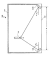
図1は、実施の形態の形態1の座標入力装置の概略構成図である。座標入力装置100は、ペンなどの入力棒(指示棒)101により、座標位置(図では位置A)を入力する矩形形状の座標入力面102と、座標入力面102に沿って照射光を発する左側光学ユニット103Lと、同様に照射光を発する右側光学ユニット103Rと、装置端部に配設され、光学ユニット103Lもしくは光学ユニット103Rが発した照射光を、その入光方向に再帰的に反射する反射部104等とからなる。また、光学ユニット103Lもしくは光学ユニット103Rは、照射光を発するほか、反射部104で反射した反射光を受光し、その受光強度も検知する。なお、以降において、光学ユニット103Lもしくは光学ユニット103Rを、適宜、光学ユニット103と称する。なお、反射部104は、照射光の照射形態によっては単なる反射材であってもよい。
【0018】
また、図において、105は、光学ユニット103で検知した受光強度および予め設定された取付角度θh(図17参照)に基づいて、光学ユニット103の取付角度θhからのズレの角度である取付ズレ角度θzを算出する取付ズレ角度算出部を示し、106は取付ズレ角度θzを用いて座標入力位置を正確に算出する算出部を、107は光学ユニット103の発光タイミングを交互に点灯・消滅するように制御する発光制御部を示す。
【0019】
反射部104は、光を再帰的に反射する部材で表面が覆われている。一例として、コーナーキューブリフレクタが挙げられる。図2は、コーナーキューブリフレクタを表す図である。図2(a)は斜視図を、図2(b)は、頂点と底面の円の中心とを通る直線における断面図である。コーナーキューブリフレクタは円錐形状で、内面をアルミ蒸着などし反射効率を高めている。図に示したとおり、コーナーキューブリフレクタは、錐角が90度であるため、入射光を再帰的に反射する。
【0020】
次に、光学ユニット103を詳細に説明する。光学ユニット103は、照射光を発する発光部110と、反射光を受光する受光部120とからなる。図3は、発光部を表す図である。図3(a)は、発光部110を座標入力面102に平行な面内で照射光の進行方向に直交する向き(図のy軸方向から)見た図であり、図3(b)は、発光部110を照射光の進行方向から(図のx軸方向から)見た図を表す。発光部110は、照射光を発する発光素子111と、発光素子111が発した照射光を所定方向に偏向するシリンドリカルレンズ112a〜シリンドリカルレンズ112cと、スリット113とからなる。なお、ハーフミラー114は、スリット113を通過した照射光を反射部104に向けて反射させるハーフミラーである。
【0021】
発光素子111は、例えば、レーザーダイオードやピンポイントLEDなどからなる。発光素子111が発した照射光はシリンドリカルレンズ112aで絞り込まれ、z軸に平行な光線となる(図3(a)参照)。続いて、照射光は2つのシリンドリカルレンズ112bおよびシリンドリカルレンズ112cを経て、y軸方向に絞り込まれ、スリット113の位置に集光する(図3(b)参照)。スリット113はx軸に平行に細長い微少空隙が設けられおり、照射光はy軸方向に扇形に広がる。すなわち、スリット113は、いわば、線光源を形成し、照射光の均一性を高める。
【0022】
図4は、受光部の内部構造を座標入力面に垂直な方向から表した概略構成図である。ここでは簡単のため、座標入力面102に平行な2次元平面内における反射光の検出についての説明を行う。受光部120は、反射部104で反射された反射光を集光する受光レンズ121と、フォトセンサなどから構成され受光強度を検知する受光素子122とからなる。また、図では、発光素子111と、反射光を透過するハーフミラー114もそれぞれ表されている。なお、発光素子111は、ハーフミラー114の上部(図における座標系においてz>0の位置)にあるので、ここでは、点で表示する。発光素子111から照射し反射部104で反射され、同じ経路を戻ってきた反射光は、受光レンズ121によって、受光素子122上のそれぞれ異なる位置に到達する。
【0023】
したがって、座標入力面102上のある位置Bに入力棒101が挿入され照射光が遮断されると、その方向に対応する受光素子122上の点に反射光が到達しなくなる。座標入力面102上に遮光物がない場合は、受光素子122上の受光強度分布はほぼ一定となる。しかし、図に示すように座標入力面102上の位置Bに光を遮る入力棒101が挿入された場合、ここを通過する光は遮られ、受光素子122上では位置Dにおいて受光強度の弱い領域(暗点)が生じる。この位置Dは遮られた光の角度、すなわち、入力棒101の検出角度θdと1対1に対応しており、受光素子122上の暗点の位置Dが分かればθdを知ることができる。レンズから受光素子122までの距離をfとして、θd(θd’)はDの関数として式(1)で与えられる。
θd=arctan(D/f) ・・・(1)
【0024】
なお、厳密には、受光レンズ121による光の屈折により、tan(θd)=D/fとならないが、θdとD/fとの関係は一意に決まるので、ここでは、簡単のため式(1)が成立するものとして取り扱う。
【0025】
図5は、座標入力装置の指示位置Bと、光学ユニット間距離wと、指示位置Bを計算する際に使用する左側計算角度θcRおよび右側計算角度θcLとの関係を表す図である。なお、以降において、大文字Lは左側光学ユニット103Lで採用する各種パラメータを識別する指標とし、大文字Rは右側光学ユニット103Rで採用する各種パラメータを識別する指標とする。詳細な計算課程は省略するが、座標入力位置(x、y)は、式(2)によって与えられる。

したがって、受光素子122上の基準点の検出位置より光学ユニットの取付ズレ角度θzさえ分かれば、計算角度θcを算出でき、式(2)により座標入力位置を算出できる。
【0027】
座標入力装置100は、取付ズレ角度θzを反射部104の反射特性を用いて求める。図6は、座標入力面に遮蔽物がない場合の発光部の発光状態と受光部の受光強度との関係を表す図である。このうち、図6(a)は右側発光部のプローブ光の照射時(左側発光部は消灯)における左側発光部における受光強度を表す図であり、図6(b)は、右側発光部のプローブ光の照射時(左側発光部は消灯)における右側発光部における受光強度を表す図であり、図6(c)は、左側発光部のプローブ光の照射時(右側発光部は消灯)における右側発光部における受光強度を表す図であり、図6(d)は、左側発光部のプローブ光の照射時(右側発光部は消灯)における左側発光部における受光強度を表す図である。
【0028】
図6に示したように、交互に点灯・消滅するような光学ユニット103の発光タイミングは発光制御部107によって行われる。
【0029】
図から明らかなように、一方の光学ユニット303が発した照射光を同じユニット303で受光する場合は、受光強度は検出角度θd(θd’)に依存せず、略一定である(図6(b)、図6(d)参照)。反対に、一方の光学ユニット303が発した照射光を他方の光学ユニット303で受光する場合は、直接光と正規反射光に相当する検出角度θd(θd’)のプローブ光を強く検知する。
【0030】
図7は、直接光と正規反射光の受光関係を表す説明図である。直接光とは、光学ユニット間を結ぶ直線上、すなわち、計算基準線(図17参照)方向を進む照射光をいい、正規反射光とは、計算基準線に対向する反射部104で反射される反射光である。正規反射光が検出されるのは、照射光は、原則的に、反射部104により再帰的に反射されるが、例えばコーナーキューブリフレクタ同士の接合部分や、反射部104の反射材が塗布されていない部分等では、通常の反射(正規反射)をするからである。
【0031】
なお、取付ズレ角度θzは、直接光の受光強度のみを用いて検出することができる。反対に、取付ズレ角度θzは、正規反射光の受光強度のみを用いて検出することもできる。また、直接光と正規反射光の両方を用いて取付ズレ角度θzを検出してもよい。
【0032】
取付ズレ角度算出部105は、光学ユニット303が検出した直接光もしくは正規反射光の検出方向θd0’を入力し、所定の取付角度θhで光学ユニット303が取り付けられている場合の直接光もしくは正規反射光の検出方向θd0を用いて、θzを算出する(θz=θd0−θd0’)。
【0033】
その後、算出部106において、取付ズレ角度θzを基に、式(2)を用いて光学ユニット303の取付ズレを補正して正確な座標入力位置を計算する。
【0034】
実施の形態1の座標入力装置100は、θzを求める際に、入力棒による基準点の指示は不要である。また、実施の形態1の座標入力装置100は、例えば、電源を投入するだけで、取付ズレ角度θzを検出でき、ユーザに特段の操作を強いないので利便性も向上したものとなる。このことは、ユーザにとって利益になるばかりでなく、製造ラインの最終段階で電源を投入して製品チェックをする際に、取付ズレ角度θzが検出されるので、入力棒が必要な場合に比して生産性が向上するといった利点も備えることとなる。
【0035】
実施の形態2.
実施の形態1では、一方の光学ユニットが発光している場合は、他方の光学ユニットは消灯していた。実施の形態2では、この様な制御を行うことなく取付ズレ角度θzを検出可能な座標入力装置について説明する。なお、本実施の形態では、実施の形態1と異なる部分についてのみ説明するものとし、重複する部分については説明を省略する。
【0036】
図8は、両方の光学ユニットがともに照射光を発している状態で座標入力面に遮蔽物がない場合の発光部の発光状態と受光部の受光強度との関係を表す図である。図8(a)は左側受光部の受光強度を、図8(b)は右側受光部の受光強度を表す。図から明らかなように、受光強度は、自己の光学ユニットが発し、再帰的に反射された反射光と、他方の光学ユニットが発した直接光と正規反射光との重ね合わせとなる。よって、両方の光学ユニットがともに照射光を発している場合であっても、直接光もしくは正規反射光を検出できる。これにより、取付ズレ角度θzが算出でき、正確な座標入力位置を算出可能となる。
【0037】
なお、両方の光学ユニットがともに照射光を発している場合は、実施の形態1で説明した場合のように、一方点灯他方消灯の関係にある場合より、検出精度が低くなることもある。したがって、適宜、時間平均をとることによりノイズを低減するなどして検出精度の向上を図るようにしてもよい。このときは、照射光を一定時間以上発する。一例を図8(c)に示した。これは、右側受光強度(図8(a)参照)の時間平均をとった受光強度を表す図である。
【0038】
実施の形態2では、取付ズレ角度θzは、基準点なるものが不必要で、かつ、座標入力装置の電源を投入するだけで検出できるので、座標入力面の見やすさを損ねることなく、利便性も向上する。また、実施の形態1の様に一方点灯他方消灯といった制御が不要であるので回路構成が簡単となり、専用の指示棒も不要であるので、利便性のさらに向上した座標入力装置を低コストで提供することが可能となる。
【0039】
実施の形態3.
実施の形態1または2では、他方の光学ユニットが発する直接光もしくは正規反射光を検出することによりθzを求めていた。すなわち、θzを求めるには原理的に他方の光学ユニットを利用する必要があった。実施の形態3では、反射部の配置形状による反射特性から、単独の光学ユニットでθzを求める座標入力装置について説明する。なお、実施の形態3では、実施の形態1または2と同一の部分の説明は省略し、異なる部分のみ説明するものとする。
【0040】
図9は、左側光学ユニットのみが照射光を発している場合の左側光学ユニットの受光素子の受光強度を表した図である。同様に、図10は、右側光学ユニットのみが照射光を発している場合の右側光学ユニットの受光部の受光強度を表した図である。このうち図9(b)および図10(b)は、受光強度の時間平均をとった図である。
【0041】
図から明らかなように、受光強度はある検出角度θd’部分でギャップ(段差)を検出している。これは、光学ユニット103に対向する位置の反射部104(矩形形状に配置された反射部104の角)で発生する。一般に反射部104は、反射部104に直角に照射光が入光した場合にもっとも反射強度が大きくなり、斜めに入光するほど反射強度が弱くなるという特性を有する。
【0042】
図11は、反射部の角で受光強度が変化する様子を説明する説明図である。左側光学ユニット103Lで発せられた照射光は、コーナーキューブリフレクタ1〜コーナーキューブリフレクタ3で反射される。照射光1〜照射光3の反射を考える。照射光1〜照射光3は、当初の発光強度は同じである。しかし照射光1は、コーナーキューブリフレクタ1に入射する入射角が非常に浅いため、その表面の影響を大きく受け、反射強度が弱くなる。一方照射光3では、入射角が深いので、反射光の反射強度は変わらない。よって、反射部104の角では、反射強度にギャップが生じる。図9(a)もしくは図10(a)の受光強度の変化はこの様な理由によって発生する。したがって、反射部104の角の方向を基準検出角度θd0’として、これと設計上予め定まっている所定の基準検出角度θd0から、取付ズレ角度θzを算出することが可能となる。
【0043】
実施の形態3の座標入力装置は、反射部104の角による受光強度の段差を利用して取付ズレ角度θzを算出するので、取付ズレ角度θzの算出に、他方の光学ユニットを必要としない。換言すれば、θzの算出には、基準点なるものが不要で、かつ、座標入力装置の電源を投入するだけで検出可能とすることができる。したがって、座標入力面の見やすさが損なわれず、利便性も向上する。また、実施の形態1の一方点灯他方消灯といった制御が不要であるので回路構成が簡単になり、専用の指示棒も不要であるので、座標入力装置をさらに低コストで提供可能となる。
【0044】
実施の形態4.
実施の形態4は、反射部の角を部分的に調整することにより反射部の反射強度を変化可能な座標入力装置について説明する。図12は実施の形態4の座標入力装置の概略構成図である。座標入力装置200は、ペンなどの入力棒(指示棒)201により、座標位置を入力する矩形形状の座標入力面(表示面)202と、座標入力面202に沿って照射光を発する左側光学ユニット203Lと、同様に照射光を発する右側光学ユニット203Rと、装置端部に配設され、光学ユニット203が発した照射光を、その入光方向に再帰的に反射する反射部204等とからなる。
【0045】
また、光学ユニット203Lもしくは光学ユニット203Rは、照射光を発するほか、反射部204で反射した反射光を受光し、その受光強度も検知する。なお、以降において、光学ユニット203Lもしくは光学ユニット203Rを、適宜、光学ユニット203と称する。
【0046】
また、反射部204のうち、反射部204Lは左側反射部を、反射部204Rは右側反射部を、反射部204Uは上部反射部を、反射部204ULは左上側反射部を、反射部204URは右上側反射部をそれぞれ示す。また、光学ユニット203および反射部204は、ネジなどを用いてフレーム205に固定されている。
【0047】
座標入力装置200は、例えば、実施の形態3で説明したように、反射部204の角部方向の受光強度の変化から、取付ズレ角θzを算出する。一般に、受光強度の変化は反射部204を構成する部材により著しく異なる。したがって、受光素子の検出特性に合致したものであればθzの検出に有効であるが、受光素子の検出特性に合致していない場合は、θzを検出できなくなる。図13は、受光レンズ121により集光される反射光の受光量と、受光素子122の検出特性に基づく検出上限および検出下限を表した図である。
【0048】
受光素子122の検出上限と検出下限との差をレンジというが、反射部204の受光強度が角部で急激に変化する場合に、レンジを大きくとると、通常の座標入力点の検出精度が悪くなる場合がある。反対に、レンジを小さくとると、角部の方向を正確に検出できず、取付ズレ角θzに誤差が生じてしまう。したがって、反射部104の角部を調整して、角部における受光強度の変化量を調整する必要がある。
【0049】
図14は左上側反射部を拡大した図である。各反射部204は固定ネジ206により固定される。左上反射部204ULは固定ネジ206で2カ所ネジ止めすることにより、フレーム205に固定する。そのうち、1カ所のネジ穴207は、長穴状に穴開けされており、他方のねじ穴(固定ねじ206用の穴)を回動中心として、左上反射部204ULを回転可能とする。したがって、左上側反射部204ULの向きを調整することにより、照射光の入光する方向を変化させることができる。これにより、受光素子の検出特性(レンジ)を考慮して最適な座標位置検出精度を確保することが可能となる。換言すれば、光学ユニット203の取付精度および発光部の取付角度精度のばらつきが吸収され、精度よい座標位置を算出可能となる。
【0050】
実施の形態4の座標入力装置は、反射部の角を部分的に調整できるため、受光素子の検出強度の調整が可能となり、座標位置を精度よく検出することが可能となる。
【0051】
図15は、本発明の座標入力装置100(200)を電子黒板システム400に適用した場合の外観構成図である。電子黒板システム400は図示のごとく大型の表示装置(例えばプラズマディスプレイ)を有しており、その前面に本発明の座標入力装置100(200)が配設されている。このような大型の表示装置に座標入力装置100(200)を適用した場合、特に座標入力位置の検出精度の向上が顕著となり、有利な効果を奏する。
【0052】
【発明の効果】
以上説明したように、本発明の座標入力装置(請求項1)は、座標位置を検出するプローブ光を発する発光部とプローブ光を受光して受光強度を検知する受光部とから構成される2つの光学ユニットを有し、プローブ光が遮蔽された方向を受光強度から検出することにより、座標位置を算出する座標入力装置において、受光部で検知した受光強度および予め設定された取付角度に基づいて、光学ユニットの取付角度からのズレの角度である取付ズレ角度を算出する取付ズレ角度算出手段を備え、一方の光学ユニットは、他方の光学ユニットの発光部が発したプローブ光を一方の光学ユニットの受光部で受光して受光強度を検知し、他方の光学ユニットは、一方の光学ユニットの発光部が発したプローブ光を他方の光学ユニットの受光部で受光して受光強度を検知し、取付ズレ角度算出手段は、他方の光学ユニットの発光部が発したプローブ光を一方の光学ユニットの受光部で検知した受光強度を用いて、一方の光学ユニットの取付ズレ角度を算出し、一方の光学ユニットの発光部が発したプローブ光を他方の光学ユニットの受光部で検知した受光強度を用いて、他方の光学ユニットの取付ズレ角度を算出するものであるため、座標入力面の見やすさを損ねず、取付角度の補正を容易にし利便性の向上を図った座標入力装置を提供することが可能となる。
【0053】
また、本発明の座標入力装置(請求項2)は、2つの光学ユニットの発光部が同時に発光する場合、取付ズレ角度算出手段は、一方の光学ユニットの受光部で受光した受光強度から、他方の光学ユニットの発光部が発したプローブ光に対応する受光強度を抽出し、一方の光学ユニットの取付ズレ角度を算出し、他方の光学ユニットの受光部で受光した受光強度から、一方の光学ユニットの発光部が発したプローブ光に対応する受光強度を抽出し、他方の光学ユニットの取付ズレ角度を算出するものであるため、座標入力面の見やすさを損ねず、取付角度の補正を容易にし利便性の向上を図った座標入力装置を提供することが可能となる。
【0054】
また、本発明の座標入力装置(請求項3)は、矩形形状の座標入力面と、座標位置を検出するプローブ光を発する発光部とプローブ光を受光して受光強度を検知する受光部とから構成される2つの光学ユニットと、発光部で発したプローブ光を反射する反射部と、を有し、2つの光学ユニットが座標入力面のいずれか1辺の両端に配設され、反射部が座標入力面の他の3辺にわたって配設されている座標入力装置において、受光部で検知した受光強度および予め設定された取付角度に基づいて、光学ユニットの取付角度からのズレの角度である取付ズレ角度を算出する取付ズレ角度算出手段と、発光部の発光タイミングを交互に点灯・消滅するように制御する発光制御手段と、を備え、取付ズレ角度算出手段は、一方の光学ユニットの発光部が発したプローブ光を他方の光学ユニットの受光部で検知した受光強度を用いて、他方の光学ユニットの取付ズレ角度を算出するものであるため、座標入力面の見やすさを損ねず、取付角度の補正を容易にし利便性のさらなる向上を図った座標入力装置を提供することが可能となる。
【0055】
また、本発明の座標入力装置(請求項4)は、取付ズレ角度算出手段が、一方の光学ユニットの発した直接光のうち他方の光学ユニットが受光する直接光の受光強度を用いて、他方の光学ユニットの取付ズレ角度を算出するものであるため、座標入力面の見やすさを損ねず、取付角度の補正を容易にし利便性の向上を図った座標入力装置を提供することが可能となる。
【0056】
また、本発明の座標入力装置(請求項5)は、取付ズレ角度算出手段が、一方の光学ユニットの発した直接光のうち反射部で正規反射され他方の光学ユニットが受光する正規反射光の受光強度を用いて、他方の光学ユニットの取付ズレ角度を算出するものであるため、座標入力面の見やすさを損ねず、取付角度の補正を容易にし利便性の向上を図った座標入力装置を提供することが可能となる。
【0057】
また、本発明の座標入力装置(請求項6)は、矩形形状の座標入力面と、座標位置を検出するプローブ光を発する発光部とプローブ光を受光して受光強度を検知する受光部とから構成される2つの光学ユニットと、発光部で発したプローブ光を反射する反射部と、を有し、2つの光学ユニットが座標入力面のいずれか1辺の両端に配設され、反射部が座標入力面の他の3辺にわたって配設されている座標入力装置において、受光部で受光した受光強度のうち、反射部の角における反射特性の変化に対応する受光強度の変化および予め設定された取付角度に基づいて、光学ユニットの取付角度からのズレの角度である取付ズレ角度を算出する取付ズレ角度算出手段を具備するものであるため、座標入力面の見やすさを損ねず、取付角度の補正を容易にし利便性の向上を図った座標入力装置を提供することが可能となる。
【0058】
また、本発明の座標入力装置(請求項7)は、反射部が、反射部の角の反射部の反射強度を変化可能にしたものであるため、座標入力面の見やすさを損ねず、取付角度の補正を容易にし利便性の向上を図った座標入力装置を提供することが可能となる。
【0059】
また、本発明の座標入力装置(請求項8)は、反射部が、光学ユニットに対向する位置の反射部の取付角度を部分的に調整可能であるものであるため、座標入力面の見やすさを損ねず、取付角度の補正を容易にし利便性の向上を図った座標入力装置を提供することが可能となる。
【0060】
また、本発明の座標入力装置(請求項9)は、取付ズレ角度を補正して座標位置を算出する算出手段を具備するものであるため、座標入力面の見やすさを損ねず、取付角度の補正を容易にし利便性の向上を図った座標入力装置を提供することが可能となる。
【図面の簡単な説明】
【図1】実施の形態1の座標入力装置の概略構成図である。
【図2】コーナーキューブリフレクタを表す図である。
【図3】実施の形態1の座標入力装置の発光部を表す図である。
【図4】受光部の内部構造を座標入力面に垂直な方向から表した概略構成図である。
【図5】座標入力装置の指示位置Bと、光学ユニット間距離wと、指示位置Bを計算する際に使用する左側計算角度θcRおよび右側計算角度θcLとの関係を表す図である。
【図6】座標入力面に遮蔽物がない場合の発光部の発光状態と受光部の受光強度との関係を表す図である。
【図7】直接光と正規反射光の受光関係を表す説明図である。
【図8】両方の光学ユニットがともに照射光を発している状態で座標入力面に遮蔽物がない場合の発光部の発光状態と受光部の受光強度との関係を表す図である。
【図9】左側光学ユニットのみが照射光を発している場合の左側光学ユニットの受光素子の受光強度を表した図である。
【図10】右側光学ユニットのみが照射光を発している場合の右側光学ユニットの受光部の受光強度を表した図である。
【図11】反射部の角で受光強度が変化する様子を説明する説明図である。
【図12】実施の形態4の座標入力装置の概略構成図である。
【図13】受光レンズにより集光される反射光の受光量と、受光素子の検出特性に基づく検出上限および検出下限を表した図である。
【図14】左上側反射部を拡大した図である。
【図15】本発明の座標入力装置を電子黒板システムに適用した場合の外観構成図である。
【図16】従来の座標入力装置の概略構成図である。
【図17】光学ユニットの取付角度と、座標入力位置を計算する計算角度との関係を表す図である。
【符号の説明】
100、200、300 座標入力装置
101、201、301 入力棒
102、202、302 座標入力面
103、203、303 光学ユニット
104、204、304 反射部
105 取付ズレ角度算出部
106 算出部
107 発光制御部
110 発光部
120 受光部
121 受光レンズ
122 受光素子
204UL 左上側反射部
204RL 右上側反射部
207 ねじ穴
400 電子黒板システム
θc 計算角度
θd 検出角度(取付ズレなし)
θd’ 検出角度(取付ズレ有)
θh 取付角度
θz 取付ズレ角度
θd0 基準点検出角度(取付ズレなし)
θd0’ 基準点検出角度(取付ズレ有)[0001]
BACKGROUND OF THE INVENTION
The present invention relates to a coordinate input device, and more particularly, to a coordinate input device that receives and emits probe light for detecting a coordinate position and detects a direction in which the probe light is shielded from received light intensity to calculate a coordinate position.
[0002]
[Prior art]
As a conventional coordinate input device, the reference point drawn on the device is shielded by a coordinate input bar, etc., so that the optical unit mounting misalignment angle is detected, thereby correcting the angle and calculating the coordinate input position accurately. There is an input device. FIG. 16 is a schematic configuration diagram of a conventional coordinate input device. The
[0003]
The shielding direction is detected based on the dark spot position on the light receiving element of the optical unit 303, as will be described later. FIG. 17 is a diagram illustrating the relationship between the mounting angle of the optical unit and the calculation angle for calculating the coordinate input position. The shielding direction of the irradiation light by the
[0004]
However, if the optical unit 303 is mounted out of the mounting angle θh, the correct calculation angle θc cannot be calculated. As shown in the figure, assuming that the angle of attachment deviation (attachment deviation angle) is θz, the calculated angle θc is calculated as θc = θd ′ + θz + θh, where θd ′ is the detected angle detected by the optical unit 303 attached in a shifted manner. .
[0005]
Conventionally, in order to detect the attachment displacement angle θz, the reference point detection angle θd0 ′ is measured by indicating the reference point drawn on the
[0006]
[Problems to be solved by the invention]
However, the conventional coordinate input device has the following problems. In the conventional coordinate input device, in principle, it is necessary that the reference point to be indicated by the input bar is drawn on the coordinate input surface, so that the visibility of the coordinate input surface may be impaired. was there. Further, the attachment displacement angle θz is a value necessary for accurately calculating the coordinate input position. Therefore, in order to ensure its accuracy, the input rod used must satisfy various conditions such as thickness, length, low reflectivity of the surface, etc. There was a problem that a stick was necessary and it was inconvenient. In addition, for the actual reference point indication, attention must be paid to the insertion angle, and there is a problem that the burden on the user is large and the convenience is low.
[0007]
The present invention has been made in view of the above, and it is an object of the present invention to provide a coordinate input device that does not impair the visibility of the coordinate input surface, facilitates correction of the mounting angle, and improves convenience.
[0008]
[Means for Solving the Problems]
In order to solve the above-described object, the coordinate input device according to claim 1 includes a light emitting unit that emits probe light for detecting a coordinate position and a light receiving unit that receives the probe light and detects light reception intensity. In the coordinate input device that calculates the coordinate position by detecting the direction in which the probe light is shielded from the received light intensity, the received light intensity detected by the light receiving unit and a preset value are set. Based on the mounting angle, the optical unit includes a mounting shift angle calculating means for calculating a mounting shift angle that is a shift angle from the mounting angle of the optical unit, and one optical unit emits a light emitting portion of the other optical unit. Probe light is received by the light receiving unit of the one optical unit to detect the received light intensity, and the other optical unit is a projector emitted from the light emitting unit of the one optical unit. Light is received by the light receiving unit of the other optical unit to detect the received light intensity, and the mounting angle calculating means receives the probe light emitted from the light emitting unit of the other optical unit. Using the received light intensity detected by the optical unit, the mounting deviation angle of the one optical unit is calculated, and the received light intensity detected by the light receiving part of the other optical unit is detected by the light emitting part of the one optical unit Is used to calculate the mounting misalignment angle of the other optical unit.
[0009]
According to a second aspect of the present invention, in the coordinate input device according to the first aspect, when the light emitting portions of the two optical units emit light at the same time, the attachment displacement angle calculating means is configured to use the one optical unit. From the received light intensity received by the light receiving part of the unit, the received light intensity corresponding to the probe light emitted by the light emitting part of the other optical unit is extracted, the mounting misalignment angle of the one optical unit is calculated, and the other optical unit is calculated. The light receiving intensity corresponding to the probe light emitted from the light emitting section of the one optical unit is extracted from the light receiving intensity received by the light receiving section of the unit, and the mounting misalignment angle of the other optical unit is calculated.
[0010]
The coordinate input device according to claim 3 includes a rectangular coordinate input surface, a light emitting unit that emits probe light for detecting a coordinate position, and a light receiving unit that receives the probe light and detects light reception intensity. Two optical units, and a reflection part that reflects the probe light emitted from the light emitting part, and the two optical units are disposed at both ends of any one side of the coordinate input surface, In the coordinate input device in which the reflection part is arranged over the other three sides of the coordinate input surface, based on the received light intensity detected by the light receiving part and a preset attachment angle, the attachment angle of the optical unit is determined. Mounting angle calculating means for calculating a mounting deviation angle that is an angle of deviation, and light emission control means for controlling the light emission timing of the light emitting portion to be alternately turned on and off, and the attachment deviation angle. Calculating means is a probe light emitting portion is emitted in one optical unit with a received light intensity detected by the light receiving portion of the other optical unit, for calculating a mounting deviation angle of the other optical unit.
[0011]
According to a fourth aspect of the present invention, there is provided the coordinate input device according to the third aspect, wherein the attachment deviation angle calculating means is configured such that the other optical unit out of the direct light emitted by the one optical unit is The mounting misalignment angle of the other optical unit is calculated using the received light intensity of the direct light received.
[0012]
The coordinate input device according to claim 5, wherein the attachment deviation angle calculation means is a normal reflection that is regularly reflected by the reflecting portion and received by the other optical unit among direct light emitted by the one optical unit. The mounting misalignment angle of the other optical unit is calculated using the light receiving intensity of light.
[0013]
The coordinate input device according to claim 6 includes a rectangular coordinate input surface, a light emitting unit that emits probe light for detecting a coordinate position, and a light receiving unit that receives the probe light and detects light reception intensity. Two optical units, and a reflection part that reflects the probe light emitted from the light emitting part, and the two optical units are disposed at both ends of any one side of the coordinate input surface, In the coordinate input device in which a reflection part is arranged over the other three sides of the coordinate input surface, the received light intensity corresponding to a change in reflection characteristics at the corner of the reflection part among the received light intensity received by the light receiving part. And a mounting shift angle calculating means for calculating a mounting shift angle, which is a shift angle from the mounting angle of the optical unit, based on the change and the preset mounting angle.
[0014]
A coordinate input device according to a seventh aspect is the coordinate input device according to the sixth aspect, wherein the reflection portion is capable of changing a reflection intensity of a reflection portion at a corner of the reflection portion.
[0015]
The coordinate input device according to
[0016]
The coordinate input device according to claim 9 is the coordinate input device according to any one of claims 1 to 8, wherein calculation means for correcting the attachment displacement angle and calculating the coordinate position is provided. It has.
[0017]
DETAILED DESCRIPTION OF THE INVENTION
Hereinafter, embodiments of the present invention will be described in detail with reference to the drawings.
Embodiment 1 FIG.
FIG. 1 is a schematic configuration diagram of the coordinate input device according to the first embodiment. The coordinate
[0018]
Further, in the figure,
[0019]
The surface of the
[0020]
Next, the optical unit 103 will be described in detail. The optical unit 103 includes a
[0021]
The
[0022]
FIG. 4 is a schematic configuration diagram showing the internal structure of the light receiving unit from a direction perpendicular to the coordinate input surface. Here, for simplicity, detection of reflected light in a two-dimensional plane parallel to the coordinate
[0023]
Therefore, when the
θd = arctan (D / f) (1)
[0024]
Strictly speaking, tan (θd) = D / f is not satisfied due to light refraction by the
[0025]
FIG. 5 is a diagram showing the relationship between the designated position B of the coordinate input device, the distance w between the optical units, and the left calculated angle θcR and the right calculated angle θcL used when calculating the designated position B. Hereinafter, the capital letter L is used as an index for identifying various parameters used in the left
Therefore, if the mounting deviation angle θz of the optical unit is known from the detection position of the reference point on the
[0027]
The coordinate
[0028]
As shown in FIG. 6, the light
[0029]
As is apparent from the figure, when the irradiation light emitted from one optical unit 303 is received by the same unit 303, the received light intensity does not depend on the detection angle θd (θd ′) and is substantially constant (FIG. 6 ( b), see FIG. 6 (d)). On the contrary, when the irradiation light emitted from one optical unit 303 is received by the other optical unit 303, probe light having a detection angle θd (θd ′) corresponding to direct light and regular reflected light is strongly detected.
[0030]
FIG. 7 is an explanatory diagram showing the light receiving relationship between direct light and regular reflected light. Direct light refers to irradiation light that travels on a straight line connecting the optical units, that is, in the direction of the calculation reference line (see FIG. 17), and the regular reflection light is reflected by the
[0031]
The attachment displacement angle θz can be detected using only the light receiving intensity of direct light. On the contrary, the attachment deviation angle θz can be detected using only the received light intensity of the regular reflected light. Further, the attachment displacement angle θz may be detected using both direct light and regular reflected light.
[0032]
The mounting deviation
[0033]
Thereafter, the
[0034]
The coordinate
[0035]
In the first embodiment, when one optical unit emits light, the other optical unit is turned off. In the second embodiment, a coordinate input device capable of detecting the attachment displacement angle θz without performing such control will be described. In the present embodiment, only parts different from those in the first embodiment will be described, and description of overlapping parts will be omitted.
[0036]
FIG. 8 is a diagram illustrating the relationship between the light emission state of the light emitting unit and the light reception intensity of the light receiving unit when both optical units emit irradiation light and there is no shield on the coordinate input surface. FIG. 8A shows the received light intensity of the left light receiving unit, and FIG. 8B shows the received light intensity of the right light receiving unit. As is apparent from the figure, the received light intensity is a superposition of the reflected light recursively reflected by the self optical unit and the direct light and the regular reflected light emitted by the other optical unit. Therefore, even if both optical units emit irradiation light, direct light or regular reflected light can be detected. Thereby, the attachment shift angle θz can be calculated, and an accurate coordinate input position can be calculated.
[0037]
When both optical units emit irradiation light, the detection accuracy may be lower than in the case where one of the optical units is turned on and the other is turned off as described in the first embodiment. Therefore, the detection accuracy may be improved by reducing noise by taking a time average as appropriate. At this time, the irradiation light is emitted for a certain time or more. An example is shown in FIG. This is a diagram showing the light reception intensity obtained by taking the time average of the right side light reception intensity (see FIG. 8A).
[0038]
In the second embodiment, the mounting misalignment angle θz does not require a reference point, and can be detected simply by turning on the power of the coordinate input device. Therefore, the ease of viewing the coordinate input surface is not impaired. Will also improve. In addition, as in Embodiment 1, there is no need to perform control such as turning on and off one side, so the circuit configuration is simplified, and a dedicated indicator bar is also unnecessary, thus providing a coordinate input device with further improved convenience at a low cost. It becomes possible to do.
[0039]
Embodiment 3 FIG.
In
[0040]
FIG. 9 is a diagram showing the received light intensity of the light receiving element of the left optical unit when only the left optical unit emits irradiation light. Similarly, FIG. 10 is a diagram showing the light receiving intensity of the light receiving unit of the right optical unit when only the right optical unit emits irradiation light. Among these, FIG. 9B and FIG. 10B are diagrams in which the light reception intensity is averaged over time.
[0041]
As is apparent from the figure, the received light intensity detects a gap (step) at a certain detection angle θd ′. This occurs at the reflection portion 104 (the corner of the
[0042]
FIG. 11 is an explanatory diagram for explaining how the received light intensity changes depending on the angle of the reflecting portion. The irradiation light emitted from the left
[0043]
Since the coordinate input device according to the third embodiment calculates the attachment displacement angle θz using the step of the received light intensity due to the angle of the
[0044]
Embodiment 4 FIG.
In the fourth embodiment, a coordinate input device capable of changing the reflection intensity of the reflection part by partially adjusting the corner of the reflection part will be described. FIG. 12 is a schematic configuration diagram of the coordinate input device according to the fourth embodiment. The coordinate
[0045]
Further, the
[0046]
Of the reflecting portions 204, the reflecting
[0047]
For example, as described in the third embodiment, the coordinate
[0048]
The difference between the detection upper limit and the detection lower limit of the
[0049]
FIG. 14 is an enlarged view of the upper left reflective portion. Each reflecting portion 204 is fixed by a fixing
[0050]
Since the coordinate input device according to the fourth embodiment can partially adjust the corners of the reflecting portion, the detection intensity of the light receiving element can be adjusted, and the coordinate position can be detected with high accuracy.
[0051]
FIG. 15 is an external configuration diagram when the coordinate input device 100 (200) of the present invention is applied to the
[0052]
【The invention's effect】
As described above, the coordinate input device according to the present invention (Claim 1) includes the light emitting unit that emits the probe light for detecting the coordinate position and the light receiving unit that receives the probe light and detects the received light intensity. In the coordinate input device that calculates the coordinate position by detecting the direction in which the probe light is shielded from the received light intensity, based on the received light intensity detected by the light receiving unit and a preset mounting angle. , Including an attachment deviation angle calculating means for calculating an attachment deviation angle that is an angle of deviation from the attachment angle of the optical unit, wherein one optical unit emits the probe light emitted from the light emitting portion of the other optical unit to the one optical unit. The other optical unit receives the probe light emitted by the light emitting part of one optical unit by the light receiving part of the other optical unit. The light receiving intensity is detected, and the mounting misalignment angle calculating means uses the light receiving intensity detected by the light receiving part of the one optical unit to detect the probe light emitted from the light emitting part of the other optical unit. Because the angle is calculated, and the probe light emitted from the light emitting part of one optical unit is used to calculate the mounting deviation angle of the other optical unit, using the received light intensity detected by the light receiving part of the other optical unit, It is possible to provide a coordinate input device that does not impair the visibility of the coordinate input surface, facilitates correction of the mounting angle, and improves convenience.
[0053]
In the coordinate input device of the present invention (Claim 2), when the light emitting portions of the two optical units emit light at the same time, the mounting deviation angle calculating means determines the other from the received light intensity received by the light receiving portion of the one optical unit. The light receiving intensity corresponding to the probe light emitted by the light emitting part of the optical unit is extracted, the mounting displacement angle of one optical unit is calculated, and the one optical unit is obtained from the light receiving intensity received by the light receiving part of the other optical unit. The light receiving intensity corresponding to the probe light emitted by the light emitting unit is extracted, and the mounting misalignment angle of the other optical unit is calculated, which makes it easy to correct the mounting angle without compromising the visibility of the coordinate input surface. It is possible to provide a coordinate input device that is improved in convenience.
[0054]
The coordinate input device according to the present invention (Claim 3) includes a rectangular coordinate input surface, a light emitting unit that emits probe light for detecting a coordinate position, and a light receiving unit that receives the probe light and detects the light reception intensity. Two optical units that are configured, and a reflection unit that reflects the probe light emitted from the light emitting unit, the two optical units are disposed at both ends of any one side of the coordinate input surface, and the reflection unit includes In the coordinate input device arranged over the other three sides of the coordinate input surface, the mounting is a deviation angle from the mounting angle of the optical unit based on the received light intensity detected by the light receiving unit and a preset mounting angle. A mounting deviation angle calculating means for calculating a deviation angle; and a light emission control means for controlling the light emission timing of the light emitting section to be turned on and off alternately. The mounting deviation angle calculating means is a light emitting section of one optical unit. Since the emitted probe light is used to calculate the mounting misalignment angle of the other optical unit using the received light intensity detected by the light receiving section of the other optical unit, the visibility of the coordinate input surface is not impaired, and the mounting angle It is possible to provide a coordinate input device that facilitates correction and further improves convenience.
[0055]
In the coordinate input device according to the present invention (Claim 4), the mounting deviation angle calculating means uses the received light intensity of the direct light received by the other optical unit among the direct lights emitted by the one optical unit. Therefore, it is possible to provide a coordinate input device that facilitates correction of the mounting angle and improves convenience without impairing the visibility of the coordinate input surface. .
[0056]
In the coordinate input device according to the present invention (Claim 5), the mounting deviation angle calculation means is configured to transmit the normal reflected light that is regularly reflected by the reflecting portion and received by the other optical unit, out of the direct light emitted from one optical unit. Because the received optical intensity is used to calculate the mounting misalignment angle of the other optical unit, a coordinate input device that facilitates correction of the mounting angle and improves convenience without impairing the visibility of the coordinate input surface. It becomes possible to provide.
[0057]
The coordinate input device according to the present invention (Claim 6) includes a rectangular coordinate input surface, a light emitting unit that emits probe light for detecting the coordinate position, and a light receiving unit that receives the probe light and detects the light reception intensity. Two optical units that are configured, and a reflection unit that reflects the probe light emitted from the light emitting unit, the two optical units are disposed at both ends of any one side of the coordinate input surface, and the reflection unit includes In the coordinate input device arranged over the other three sides of the coordinate input surface, among the received light intensity received by the light receiving unit, the change in the received light intensity corresponding to the change in the reflection characteristic at the corner of the reflecting unit and a preset value Based on the mounting angle, it is equipped with a mounting shift angle calculating means for calculating a mounting shift angle that is a shift angle from the mounting angle of the optical unit. Correction It is possible to provide a coordinate input device with improved convenience to easily.
[0058]
In the coordinate input device according to the present invention (Claim 7), since the reflection part can change the reflection intensity of the reflection part at the corner of the reflection part, the coordinate input surface is not easily seen and attached. It is possible to provide a coordinate input device that facilitates angle correction and improves convenience.
[0059]
In the coordinate input device of the present invention (Claim 8), since the reflection portion can partially adjust the mounting angle of the reflection portion at a position facing the optical unit, it is easy to see the coordinate input surface. Therefore, it is possible to provide a coordinate input device that facilitates correction of the mounting angle and improves convenience.
[0060]
In addition, the coordinate input device according to the present invention (Claim 9) includes a calculation unit that calculates the coordinate position by correcting the mounting displacement angle. It is possible to provide a coordinate input device that facilitates correction and improves convenience.
[Brief description of the drawings]
FIG. 1 is a schematic configuration diagram of a coordinate input device according to a first embodiment.
FIG. 2 is a diagram illustrating a corner cube reflector.
FIG. 3 is a diagram illustrating a light emitting unit of the coordinate input device according to the first embodiment.
FIG. 4 is a schematic configuration diagram illustrating an internal structure of a light receiving unit from a direction perpendicular to a coordinate input surface.
FIG. 5 is a diagram illustrating a relationship between a designated position B of the coordinate input device, a distance w between optical units, and a left calculated angle θcR and a right calculated angle θcL used when calculating the designated position B.
FIG. 6 is a diagram illustrating a relationship between a light emitting state of a light emitting unit and a light receiving intensity of a light receiving unit when there is no shielding object on a coordinate input surface.
FIG. 7 is an explanatory diagram showing a light receiving relationship between direct light and regular reflected light.
FIG. 8 is a diagram illustrating a relationship between a light emission state of a light emitting unit and a light reception intensity of a light receiving unit when both optical units emit irradiation light and there is no shield on the coordinate input surface.
FIG. 9 is a diagram showing the light receiving intensity of the light receiving element of the left optical unit when only the left optical unit emits irradiation light.
FIG. 10 is a diagram showing the light receiving intensity of the light receiving unit of the right optical unit when only the right optical unit emits irradiation light.
FIG. 11 is an explanatory diagram for explaining how the received light intensity changes depending on the angle of the reflecting portion.
FIG. 12 is a schematic configuration diagram of a coordinate input device according to a fourth embodiment.
FIG. 13 is a diagram showing a detection upper limit and a detection lower limit based on the amount of reflected light collected by the light receiving lens and the detection characteristics of the light receiving element.
FIG. 14 is an enlarged view of a left upper reflection part.
FIG. 15 is an external configuration diagram when the coordinate input device of the present invention is applied to an electronic blackboard system.
FIG. 16 is a schematic configuration diagram of a conventional coordinate input device.
FIG. 17 is a diagram illustrating a relationship between an attachment angle of an optical unit and a calculation angle for calculating a coordinate input position.
[Explanation of symbols]
100, 200, 300 Coordinate input device
101, 201, 301 Input bar
102, 202, 302 Coordinate input surface
103, 203, 303 Optical unit
104, 204, 304 Reflector
105 Mounting displacement angle calculation unit
106 Calculation unit
107 Light emission controller
110 Light emitting part
120 light receiving part
121 Light receiving lens
122 Light receiving element
204UL Upper left reflector
204RL Upper right side reflector
207 Screw hole
400 electronic blackboard system
θc Calculation angle
θd Detection angle (no mounting displacement)
θd 'Detection angle (with mounting displacement)
θh Mounting angle
θz Mounting misalignment angle
θd0 Reference point detection angle (no mounting displacement)
θd0 'Reference point detection angle (with mounting displacement)
Claims (9)
前記受光部で検知した受光強度および予め設定された取付角度に基づいて、前記光学ユニットの前記取付角度からのズレの角度である取付ズレ角度を算出する取付ズレ角度算出手段を備え、
一方の光学ユニットは、他方の光学ユニットの発光部が発したプローブ光を前記一方の光学ユニットの受光部で受光して受光強度を検知し、前記他方の光学ユニットは、前記一方の光学ユニットの発光部が発したプローブ光を前記他方の光学ユニットの受光部で受光して受光強度を検知し、
前記取付ズレ角度算出手段は、前記他方の光学ユニットの発光部が発したプローブ光を前記一方の光学ユニットの受光部で検知した受光強度を用いて、前記一方の光学ユニットの取付ズレ角度を算出し、前記一方の光学ユニットの発光部が発したプローブ光を前記他方の光学ユニットの受光部で検知した受光強度を用いて、前記他方の光学ユニットの取付ズレ角度を算出することを特徴とする座標入力装置。It has two optical units composed of a light emitting part that emits probe light for detecting the coordinate position and a light receiving part that receives the probe light and detects the light receiving intensity, and the light receiving intensity is in the direction in which the probe light is shielded In the coordinate input device that calculates the coordinate position by detecting from
A mounting shift angle calculating means for calculating a mounting shift angle that is a shift angle from the mounting angle of the optical unit based on a light reception intensity detected by the light receiving unit and a preset mounting angle;
One optical unit receives the probe light emitted from the light emitting unit of the other optical unit by the light receiving unit of the one optical unit and detects the received light intensity, and the other optical unit detects the light intensity of the one optical unit. The probe light emitted by the light emitting unit is received by the light receiving unit of the other optical unit to detect the received light intensity,
The attachment deviation angle calculation means calculates the attachment deviation angle of the one optical unit by using the received light intensity detected by the light receiving part of the one optical unit of the probe light emitted from the light emitting part of the other optical unit. Then, the mounting misalignment angle of the other optical unit is calculated using the received light intensity detected by the light receiving unit of the other optical unit of the probe light emitted from the light emitting unit of the one optical unit. Coordinate input device.
前記受光部で検知した受光強度および予め設定された取付角度に基づいて、前記光学ユニットの前記取付角度からのズレの角度である取付ズレ角度を算出する取付ズレ角度算出手段と、
前記発光部の発光タイミングを交互に点灯・消滅するように制御する発光制御手段と、を備え、
前記取付ズレ角度算出手段は、一方の光学ユニットの発光部が発したプローブ光を他方の光学ユニットの受光部で検知した受光強度を用いて、前記他方の光学ユニットの取付ズレ角度を算出することを特徴とする座標入力装置。Two optical units composed of a rectangular coordinate input surface, a light emitting unit that emits probe light for detecting the coordinate position, and a light receiving unit that receives the probe light and detects the received light intensity, and the light emitting unit emits light. A reflecting portion that reflects the probe light, and the two optical units are disposed at both ends of any one side of the coordinate input surface, and the reflecting portion extends over the other three sides of the coordinate input surface. In the coordinate input device arranged,
An attachment deviation angle calculating means for calculating an attachment deviation angle, which is an angle of deviation from the attachment angle of the optical unit, based on the received light intensity detected by the light receiving unit and a preset attachment angle;
A light emission control means for controlling the light emission timing of the light emitting unit to alternately turn on and off, and
The attachment displacement angle calculation means calculates the attachment displacement angle of the other optical unit using the received light intensity detected by the light receiving portion of the other optical unit of the probe light emitted from the light emitting portion of one optical unit. Coordinate input device characterized by
前記受光部で受光した受光強度のうち、前記反射部の角における反射特性の変化に対応する前記受光強度の変化および予め設定された取付角度に基づいて、前記光学ユニットの前記取付角度からのズレの角度である取付ズレ角度を算出する取付ズレ角度算出手段を具備することを特徴とする座標入力装置。Two optical units composed of a rectangular coordinate input surface, a light emitting unit that emits probe light for detecting the coordinate position, and a light receiving unit that receives the probe light and detects the received light intensity, and the light emitting unit emits light. A reflecting portion that reflects the probe light, and the two optical units are disposed at both ends of any one side of the coordinate input surface, and the reflecting portion extends over the other three sides of the coordinate input surface. In the coordinate input device arranged,
Of the received light intensity received by the light receiving unit, a deviation from the mounting angle of the optical unit based on a change in the received light intensity corresponding to a change in reflection characteristics at a corner of the reflecting unit and a preset mounting angle. A coordinate input device comprising an attachment angle calculation means for calculating an attachment angle that is an angle of the angle.
Priority Applications (1)
| Application Number | Priority Date | Filing Date | Title |
|---|---|---|---|
| JP25820899A JP3964079B2 (en) | 1999-09-13 | 1999-09-13 | Coordinate input device |
Applications Claiming Priority (1)
| Application Number | Priority Date | Filing Date | Title |
|---|---|---|---|
| JP25820899A JP3964079B2 (en) | 1999-09-13 | 1999-09-13 | Coordinate input device |
Publications (2)
| Publication Number | Publication Date |
|---|---|
| JP2001084093A JP2001084093A (en) | 2001-03-30 |
| JP3964079B2 true JP3964079B2 (en) | 2007-08-22 |
Family
ID=17317026
Family Applications (1)
| Application Number | Title | Priority Date | Filing Date |
|---|---|---|---|
| JP25820899A Expired - Fee Related JP3964079B2 (en) | 1999-09-13 | 1999-09-13 | Coordinate input device |
Country Status (1)
| Country | Link |
|---|---|
| JP (1) | JP3964079B2 (en) |
Families Citing this family (8)
| Publication number | Priority date | Publication date | Assignee | Title |
|---|---|---|---|---|
| JP4522113B2 (en) | 2004-03-11 | 2010-08-11 | キヤノン株式会社 | Coordinate input device |
| US8803845B2 (en) * | 2009-12-26 | 2014-08-12 | Lg Display Co., Ltd. | Optical touch input system and method of establishing reference in the same |
| KR101308476B1 (en) * | 2009-12-26 | 2013-09-16 | 엘지디스플레이 주식회사 | Method For Establishing References of Optical Touch Input Device and Optical Touch Input Device Using the Same |
| JP5725774B2 (en) * | 2010-09-13 | 2015-05-27 | キヤノン株式会社 | Coordinate input device and coordinate input method |
| KR101726631B1 (en) * | 2010-11-12 | 2017-04-14 | 엘지디스플레이 주식회사 | Optical touch input device |
| JP5629595B2 (en) * | 2011-02-10 | 2014-11-19 | キヤノン株式会社 | Coordinate input device |
| JP5973849B2 (en) * | 2012-03-08 | 2016-08-23 | キヤノン株式会社 | Coordinate input device and sensor bar used for coordinate input device |
| JP5981810B2 (en) * | 2012-08-31 | 2016-08-31 | キヤノン株式会社 | Coordinate input device and control method thereof |
-
1999
- 1999-09-13 JP JP25820899A patent/JP3964079B2/en not_active Expired - Fee Related
Also Published As
| Publication number | Publication date |
|---|---|
| JP2001084093A (en) | 2001-03-30 |
Similar Documents
| Publication | Publication Date | Title |
|---|---|---|
| JP2001265516A (en) | Coordinate input device | |
| US7522156B2 (en) | Optical scanning-type touch panel | |
| US9122355B2 (en) | Indication member, optical position detection device, and display system with input function | |
| JP3934846B2 (en) | Coordinate input / detection device, electronic blackboard system, light receiving element positional deviation correction method, and storage medium | |
| JP2001014091A (en) | Coordinate input device | |
| JP2001282445A (en) | Coordinate input/detecting device and information display input device | |
| US20120212454A1 (en) | Optical position detecting device and display system provided with input function | |
| JP3964079B2 (en) | Coordinate input device | |
| EP3156822B1 (en) | Photoelectric sensor | |
| JP5521995B2 (en) | Optical position detection device and device with position detection function | |
| US20220026207A1 (en) | Surveying Instrument | |
| JP3898392B2 (en) | Coordinate input device | |
| US20150035804A1 (en) | Optical position detection device and display system with input function | |
| JP4328918B2 (en) | Distance measuring device | |
| US8854337B2 (en) | Optical position detection device, light receiving unit, and display system with input function | |
| US20110134081A1 (en) | Optical position detection device and display device with position detection function | |
| JP2000322201A5 (en) | ||
| JP4363174B2 (en) | Coordinate input device | |
| JP2008171444A (en) | Optical scanning touch panel | |
| KR20200070823A (en) | Touch display | |
| JP2009032571A (en) | Infrared ray touch switch device | |
| JP4004177B2 (en) | Optical scanning touch panel | |
| JP4531081B2 (en) | Optical scanning touch panel | |
| JP2001306257A (en) | Coordinate inputting device and position adjusting method | |
| JP2012146231A (en) | Optical position detecting device and position detecting system |
Legal Events
| Date | Code | Title | Description |
|---|---|---|---|
| A621 | Written request for application examination |
Free format text: JAPANESE INTERMEDIATE CODE: A621 Effective date: 20041015 |
|
| A977 | Report on retrieval |
Free format text: JAPANESE INTERMEDIATE CODE: A971007 Effective date: 20070209 |
|
| TRDD | Decision of grant or rejection written | ||
| A01 | Written decision to grant a patent or to grant a registration (utility model) |
Free format text: JAPANESE INTERMEDIATE CODE: A01 Effective date: 20070522 |
|
| A61 | First payment of annual fees (during grant procedure) |
Free format text: JAPANESE INTERMEDIATE CODE: A61 Effective date: 20070523 |
|
| R150 | Certificate of patent or registration of utility model |
Free format text: JAPANESE INTERMEDIATE CODE: R150 |
|
| FPAY | Renewal fee payment (event date is renewal date of database) |
Free format text: PAYMENT UNTIL: 20110601 Year of fee payment: 4 |
|
| FPAY | Renewal fee payment (event date is renewal date of database) |
Free format text: PAYMENT UNTIL: 20110601 Year of fee payment: 4 |
|
| FPAY | Renewal fee payment (event date is renewal date of database) |
Free format text: PAYMENT UNTIL: 20120601 Year of fee payment: 5 |
|
| FPAY | Renewal fee payment (event date is renewal date of database) |
Free format text: PAYMENT UNTIL: 20130601 Year of fee payment: 6 |
|
| LAPS | Cancellation because of no payment of annual fees |