JP3962003B2 - Body structure - Google Patents
Body structure Download PDFInfo
- Publication number
- JP3962003B2 JP3962003B2 JP2003356981A JP2003356981A JP3962003B2 JP 3962003 B2 JP3962003 B2 JP 3962003B2 JP 2003356981 A JP2003356981 A JP 2003356981A JP 2003356981 A JP2003356981 A JP 2003356981A JP 3962003 B2 JP3962003 B2 JP 3962003B2
- Authority
- JP
- Japan
- Prior art keywords
- floor
- vehicle body
- tunnel
- cross member
- frame
- Prior art date
- Legal status (The legal status is an assumption and is not a legal conclusion. Google has not performed a legal analysis and makes no representation as to the accuracy of the status listed.)
- Expired - Fee Related
Links
- 230000003014 reinforcing effect Effects 0.000 description 9
- 230000000052 comparative effect Effects 0.000 description 6
- 238000003466 welding Methods 0.000 description 6
- 238000010521 absorption reaction Methods 0.000 description 5
- 239000000463 material Substances 0.000 description 5
- 238000010586 diagram Methods 0.000 description 4
- 230000000694 effects Effects 0.000 description 3
- 230000005540 biological transmission Effects 0.000 description 2
- 230000000295 complement effect Effects 0.000 description 2
- 239000011324 bead Substances 0.000 description 1
- 230000037396 body weight Effects 0.000 description 1
- 238000010276 construction Methods 0.000 description 1
- 230000007423 decrease Effects 0.000 description 1
- 230000003247 decreasing effect Effects 0.000 description 1
- 239000006185 dispersion Substances 0.000 description 1
- 238000005516 engineering process Methods 0.000 description 1
- 238000000034 method Methods 0.000 description 1
- 238000005192 partition Methods 0.000 description 1
Images


Classifications
-
- B—PERFORMING OPERATIONS; TRANSPORTING
- B62—LAND VEHICLES FOR TRAVELLING OTHERWISE THAN ON RAILS
- B62D—MOTOR VEHICLES; TRAILERS
- B62D25/00—Superstructure or monocoque structure sub-units; Parts or details thereof not otherwise provided for
- B62D25/20—Floors or bottom sub-units
- B62D25/2009—Floors or bottom sub-units in connection with other superstructure subunits
- B62D25/2036—Floors or bottom sub-units in connection with other superstructure subunits the subunits being side panels, sills or pillars
-
- B—PERFORMING OPERATIONS; TRANSPORTING
- B62—LAND VEHICLES FOR TRAVELLING OTHERWISE THAN ON RAILS
- B62D—MOTOR VEHICLES; TRAILERS
- B62D21/00—Understructures, i.e. chassis frame on which a vehicle body may be mounted
- B62D21/15—Understructures, i.e. chassis frame on which a vehicle body may be mounted having impact absorbing means, e.g. a frame designed to permanently or temporarily change shape or dimension upon impact with another body
- B62D21/157—Understructures, i.e. chassis frame on which a vehicle body may be mounted having impact absorbing means, e.g. a frame designed to permanently or temporarily change shape or dimension upon impact with another body for side impacts
-
- B—PERFORMING OPERATIONS; TRANSPORTING
- B62—LAND VEHICLES FOR TRAVELLING OTHERWISE THAN ON RAILS
- B62D—MOTOR VEHICLES; TRAILERS
- B62D25/00—Superstructure or monocoque structure sub-units; Parts or details thereof not otherwise provided for
- B62D25/02—Side panels
- B62D25/025—Side sills thereof
Landscapes
- Engineering & Computer Science (AREA)
- Chemical & Material Sciences (AREA)
- Combustion & Propulsion (AREA)
- Transportation (AREA)
- Mechanical Engineering (AREA)
- Body Structure For Vehicles (AREA)
Description
本発明は、衝突エネルギーを車体全体に効率良く分散させることができる、車体構造に関する。 The present invention relates to a vehicle body structure that can efficiently disperse collision energy throughout the vehicle body.
自動車などの車両において、車体に作用する衝突エネルギーを分散させることによって、衝突エネルギーの吸収性能を高める技術の開発が進められている(例えば、特許文献1参照。)。
特許文献1を次図に基づいて説明する。
図19は従来の車体構造の概要図である。従来の車体200は、車体前部に前後に延びる左右のフロントサイドフレーム201(一方だけを示す。以下同じ。)を設け、車体中央部に前後に延びる左右のサイドシル202を設け、フロントサイドフレーム201の後端部にエクステンションメンバ203の前端部を接合し、このエクステンションメンバ203を上から見たときに、概ねL字状に形成するとともに後部を大きく広げた拡大部204とし、L字状の後部側部をサイドシル202の前部における内側に接合し、拡大部204の上にフロアパネル205を張ったというものである。拡大部204は複数の補強用ビード206・・・を有する。207は、車体前部のエンジンルームと車体中央部の車室とを仕切るダッシュロアパネルである。208は前輪用ホイールハウスである。
FIG. 19 is a schematic view of a conventional vehicle body structure. The
車体200の前方から作用した衝突エネルギーEnは、フロントサイドフレーム201からエクステンションメンバ203に伝わり、さらにエクステンションメンバ203の後部からサイドシル202の前部に伝わるとともに、拡大部204からフロアパネル205に伝わる。このようにして、前方からの衝突エネルギーEnを車体200に分散させることができる。
The collision energy En acting from the front of the
ところで、車体200に作用する衝突エネルギーとしては、前方からの衝突エネルギーEnの他に、車体側方からの衝突エネルギーもある。これに対して従来の車体200は、側方から作用する衝突エネルギーの分散に関しては考慮されていないものである。車体前方からの衝突エネルギー及び車体側方からの衝突エネルギーの両方を、車体200の全体に効率良く分散させるには、改良の余地がある。
Incidentally, the collision energy acting on the
本発明は、車体前方からの衝突エネルギー及び車体側方からの衝突エネルギーの両方を、車体全体に効率良く分散させることができる技術を提供することを課題とする。 An object of the present invention is to provide a technique capable of efficiently dispersing both collision energy from the front of the vehicle body and collision energy from the side of the vehicle body throughout the vehicle body.
請求項1に係る発明は、車幅中心から左右両側方へ、車体前後に延びるフロアフレーム及び車体前後に延びるサイドシルをこの順に並列に設け、左右のフロアフレームの前端から前方へ左右のフロントサイドフレームを延ばした車体構造において、
左右のサイドシルの長手途中に左右の上方開口且つコ字状のフロアフレームの後端部を左右のサイドシル側に湾曲させて接合し、それらの接合部分よりも前の位置で且つ接合部分の近傍で左右のサイドシル間に下方開口且つコ字状のクロスメンバを掛け渡し、このクロスメンバにフロアパネルを挟んで左右のフロアフレームをも接合することで、左のサイドシルと左のフロアフレームとクロスメンバとの間の接合部分を平面視略三角形状の接合構造とするともに、右のサイドシルと右のフロアフレームとクロスメンバとの間の接合部分を平面視略三角形状の接合構造としてなり、フロアフレームの後端部は、左右のサイドシルに向けて末広がり形状に形成したことを特徴とする。
According to the first aspect of the present invention, a floor frame extending in the front-rear direction of the vehicle body and a side sill extending in the front-rear direction of the vehicle body are provided in parallel in this order from the vehicle width center to the left and right sides, and the left and right front side frames forward from the front ends of the left and right floor frames. In the body structure that extends
In the middle of the length of the left and right side sills, the left and right upper openings and the rear ends of the U-shaped floor frame are bent and joined to the left and right side sill sides, at a position in front of and in the vicinity of the joint portion. between the left and right side sills spanned the cross member of the lower opening and U-shaped, by joining also the left and right floor frames across the floor panels to the cross member, a left side sill and the left floor frame and the cross member joining portions becomes as a plan view triangular junction structure, the floor frames between the junction and the junction structure of the plan view triangle then monitor, with the right side sill and the right floor frames and cross members between The rear end portion is formed in a shape that spreads toward the left and right side sills .
請求項1に係る発明では、左右のそれぞれで、サイドシルとフロアフレームとクロスメンバとの間の接合部分を、平面視略三角形状の接合構造、すなわち三角状接合部としたものである。三角状接合部を設けたこと及びフロアフレームの後端部を左右のサイドシルに向けて末広がり形状に形成したことにより、サイドシルとフロアフレームとクロスメンバとの間で、互いに強度や剛性を補完し合うことができる。 According to the first aspect of the present invention, in each of the left and right sides, the joint portions between the side sill, the floor frame, and the cross member have a substantially triangular joint structure in plan view, that is, a triangular joint portion. Complementing the strength and rigidity of the side sill, floor frame, and cross member with each other by providing a triangular joint and forming the rear end of the floor frame toward the left and right side sills. be able to.
車体前方から作用した衝突エネルギーを、フロントサイドフレームからフロアフレームを介して三角状接合部に伝え、さらに、この三角状接合部からクロスメンバ及びサイドシルに効率良く分散させることができる。
また、車体側方から作用した衝突エネルギーを、サイドシルから三角状接合部に伝え、さらに、この三角状接合部からフロアフレーム及びクロスメンバに効率良く分散させることができる。
The collision energy acting from the front of the vehicle body can be transmitted from the front side frame to the triangular joint via the floor frame, and further, the triangular joint can be efficiently dispersed to the cross member and the side sill.
Further, the collision energy applied from the side of the vehicle body can be transmitted from the side sill to the triangular joint, and can be efficiently dispersed from the triangular joint to the floor frame and the cross member.
このように、車体前方からの衝突エネルギー及び車体側方からの衝突エネルギーの両方を、車体全体に効率良く十分に分散させることができる。この結果、車体全体で衝突エネルギーを十分に吸収することができるので、車体による衝突エネルギーの吸収性能を高めることができる。しかも、車体の各部材を大型にしたり、各部材を補強する新たな補強部材を設ける必要はない。このため、車体の重量を抑制することができるとともに、車室内のスペースを十分に確保することができる。 Thus, both the collision energy from the front of the vehicle body and the collision energy from the side of the vehicle body can be efficiently and sufficiently dispersed throughout the vehicle body. As a result, the collision energy can be sufficiently absorbed by the entire vehicle body, so that the performance of absorbing the collision energy by the vehicle body can be improved. Moreover, it is not necessary to increase the size of each member of the vehicle body or to provide a new reinforcing member that reinforces each member. For this reason, while being able to suppress the weight of a vehicle body, the space in a vehicle interior can fully be ensured.
また、走行中には前輪からの振動が車体前部を介してフロアフレームに伝わる。この振動の方向は、フロアフレームをねじる方向が主である。
これに対して請求項1は、サイドシルとフロアフレームの後端部との接合部分よりも前の位置において、左右のサイドシル間にクロスメンバを掛け渡し、このクロスメンバにフロアフレームをも接合したので、その分、フロアフレームの長さを小さくすることができる。しかも、フロアフレームの後端を強固な三角状接合部にて接合したものである。従って、フロアフレームのねじり方向の振動を低減することができる。
Further, during traveling, vibration from the front wheels is transmitted to the floor frame via the front part of the vehicle body. The direction of this vibration is mainly the direction of twisting the floor frame.
In contrast, according to the first aspect of the present invention, the cross member is spanned between the left and right side sills at a position before the joining portion between the side sill and the rear end of the floor frame, and the floor frame is also joined to the cross member. Therefore, the length of the floor frame can be reduced. In addition, the rear end of the floor frame is joined by a strong triangular joint. Therefore, vibration in the torsional direction of the floor frame can be reduced.
本発明を実施するための最良の形態を添付図に基づいて以下に説明する。なお、「前」、「後」、「左」、「右」、「上」、「下」は運転者から見た方向に従い、Frは前側、Rrは後側、Lは左側、Rは右側、CLは車幅中心(車体中心)を示す。また、図面は符号の向きに見るものとする。 The best mode for carrying out the present invention will be described below with reference to the accompanying drawings. “Front”, “Rear”, “Left”, “Right”, “Up”, “Down” follow the direction seen from the driver, Fr is front, Rr is rear, L is left, R is right CL indicates the vehicle width center (vehicle body center). The drawings are to be viewed in the direction of the reference numerals.
図1は本発明に係る車体の平面図であり、フロアパネルを外した状態の車体10を示す。但し説明の便宜上、フロアトンネル15だけ示す。
自動車等の車両における車体10は、フロアパネルの高さを下げた低床式車体であって、前部で車体前後に延びた左右のフロントサイドフレーム11,11と、これらのフロントサイドフレーム11,11の後部側部に接合した左右のサイドアウトリガー12,12と、これらのサイドアウトリガー12,12の後部から後方へ延びた左右のサイドシル13,13と、これらのサイドシル13,13の後部から後方へ延びた左右のリヤサイドフレーム14,14と、車幅中心(車幅中央)CLで車体前後に延びたフロアトンネル15と、このフロアトンネル15の左右両側方で車体前後に延びたフロアフレーム16,16と、車幅方向に延びた6つのクロスメンバ21〜26とを、主要な構成メンバとした車体フレームである。
FIG. 1 is a plan view of a vehicle body according to the present invention, showing a
A
6つのクロスメンバ21〜26は、車体前部から後方へ第1クロスメンバ21、第2クロスメンバ22、第3クロスメンバ23、第4クロスメンバ24、第5クロスメンバ25、第6クロスメンバ26の順に配列することになる。
第1クロスメンバ21については後述する。第2・第3クロスメンバ22,23は、フロアトンネル15の後方で左右のサイドシル13,13間に掛け渡した部材である。第4・第5・第6クロスメンバ24〜26は、左右のリヤサイドフレーム14,14間に掛け渡した部材である。
The six
The
ところで、一般には、フロアトンネル15は第3クロスメンバ23まで延びる長い部材である。これに対して本発明は、車両の動力伝達方式としてFF式(フロントエンジン、フロントドライブ式)を採用したものである。フロアトンネル15の中にプロペラシャフトを通す必要はない。しかし、フロアトンネル15の前半部の近傍に各種機器を配置するので、フロアトンネル15を完全に廃止することはできない。フロアトンネル15の後半部の高さを下げることはできる。下げることによって車室を広くできるので、居住性を高めることができる。
By the way, generally, the
このような理由によって、本発明においては、フロアトンネル15の長さを第2クロスメンバ22の前方までの短いものにし、その後方については低位のセンタフレーム31,31を用いた。
具体的には、短いフロアトンネル15の後端部61を左右一対のセンタフレーム31,31を介して、第2クロスメンバ22及び第3クロスメンバ23に接合したものである。センタフレーム31,31は、車幅中心CLの左右両側方に配列して車体前後に延びる部材である。27は、左右のセンタフレーム31,31間に掛け渡した第7クロスメンバである。なお、フロアトンネル15の後端部61を第2クロスメンバ22に直接に接合する構成としてもよい。
For this reason, in the present invention, the length of the
Specifically, the
左右のフロントサイドフレーム11,11は、左右のフロアフレーム16,16の前端から前方へ延ばした部材であると言うことができる。
このようにして、車幅中心CLから左右両側方へ、車体前後に延びるフロアフレーム16,16及び車体前後に延びるサイドシル13,13を、この順に並列に設けることができる。
図中、35,35は左右の前輪、36,36は左右の後輪である。
It can be said that the left and right
In this way, the
In the figure, 35 and 35 are left and right front wheels, and 36 and 36 are left and right rear wheels.
図2は本発明に係るフロアトンネルの前部周りの車体を左側方から見た断面図である。
図2に示すように車体10は、前部をダッシュボード41にて前部のエンジンルーム42と後部の車室43とに仕切り、エンジンルーム42内で車体前後に延びる左右のフロントサイドフレーム11,11(図1参照)にエンジン搭載用サブフレーム44を取外し可能に取付けたものである。エンジン搭載用サブフレーム44はエンジン45、トランスミッション46並びにステアリング装置47を搭載した部材である。第1クロスメンバ21は、ダッシュボード41の部分における下部に配置したものである。48はエンジン排気用マフラである。
FIG. 2 is a cross-sectional view of the vehicle body around the front portion of the floor tunnel according to the present invention as viewed from the left side.
As shown in FIG. 2, the
図3は本発明に係るフロアトンネルの前部周りの車体の平面図であり、ダッシュボードを省略して表した。図4は本発明に係るフロアトンネルの前部周りを左上部から見た斜視図である。図5は本発明に係るフロアトンネルの前部周りを右上部から見た斜視図である。図6は図1の6−6線断面図である(但し、フロアパネル51を設けた状態で表した)。
FIG. 3 is a plan view of the vehicle body around the front portion of the floor tunnel according to the present invention, and the dashboard is omitted. FIG. 4 is a perspective view of the floor tunnel according to the present invention as viewed from the upper left part around the front part. FIG. 5 is a perspective view of the periphery of the front portion of the floor tunnel according to the present invention as seen from the upper right portion. 6 is a cross-sectional view taken along line 6-6 in FIG. 1 (however, the
図3に示すように、左右のフロントサイドフレーム11,11は後端部の内側面に、それぞれブラケット52,52を備える。これらのブラケット52,52に想像線にて示すエンジン搭載用サブフレーム44の後端部を取外し可能に取付けることで、フロントサイドフレーム11,11にエンジン搭載用サブフレーム44を取付けることができる。
As shown in FIG. 3, the left and right front side frames 11, 11 are provided with
フロアトンネル15の全体形状は、図3〜図5に示すように、前端部62から後方へ徐々に小さくなる、いわゆる概ね流線形である。具体的には、フロアトンネル15は平面視略矩形状であって、上面63を前端部62から後方へ下り勾配となるように傾斜させた形状を有する。
より詳しくは図6に示すように、フロアトンネル15は板材からなる折曲げ成形品であって、正面から見たときに略下向きコ字状(略下向きU字状)に形成した略下向きコ字状断面体であり、左右両端からそれぞれ対抗するサイドシル13,13に向かって延びる水平なフランジ64,64を有する。フロアトンネル15の板厚は、フロアパネル51の板厚よりも大きい。
As shown in FIGS. 3 to 5, the overall shape of the
More specifically, as shown in FIG. 6, the
図6に示すようにフロアパネル51は、左右のフロアフレーム16,16(一方だけを示す。)の上及びフロアトンネル15の上にフロアパネル51を重ねて接合するとともに、左右のサイドシル13,13(一方だけを示す。)にも接合した薄板である。このようにして、フロアトンネル15にフロアパネル51を連ねることができる。フロアパネル51の床面に対してフロアトンネル15は高位にある。
As shown in FIG. 6, the
図3〜図6に示すように、このようなフロアトンネル15、すなわち下向きコ字状断面体15は、左右の上部コーナ65,65(図6参照)を一段下がった段差状に形成することで、左右の段差部66,66を有する。段差部66は、上面63から下方へ延びた垂下部66aと、垂下部66aの下端から側方へ延びた段差面部66bとからなる。段差部66,66が上面63に沿って後下方へ下がるので、段差面部66b、66bも後下方へ下がって、その後端がフランジ64,64に合致する。
As shown in FIGS. 3 to 6, such a
図3及び図4に示すように、フロアトンネル15の後端部61は左右二股状に分かれ、これらの二股状分岐部に左右一対のセンタフレーム31,31の先端をスポット溶接等によって接合したものである。センタフレーム31,31は断面視略ハット状の細長いビームである。
As shown in FIGS. 3 and 4, the
次に、左右のフロアフレーム16,16とフロアトンネル15との連結関係について説明する。
図7は図6に示す右のフロアフレーム及びフロアトンネル周りの要部拡大図であり、フロアフレーム16とフロアトンネル15との関係を示す。
右のフロアフレーム16は、正面視上開放の略U字状断面のフレーム本体71の上に略平板状のカバー部73を被せて、スポット溶接等によって互いに接合することで、閉断面構造としたビームである。フレーム本体71は上端から左右に延びるフランジ72,72を備える。
右のフロアフレーム16、すなわち、フレーム本体71並びにカバー部73は板材からなる折曲げ成形品である。フレーム本体71並びにカバー部73の板厚は、フロアパネル51の板厚よりも大きい。
Next, the connection relationship between the left and right floor frames 16 and 16 and the
FIG. 7 is an enlarged view of a main part around the right floor frame and the floor tunnel shown in FIG. 6, and shows the relationship between the
The
The
図4、図5及び図7に示すようにフロアフレーム16は、このフロアフレーム16を構成する板材のうち略水平な部分の一部、例えば、カバー部73の一部をフロアトンネル15側へ延ばし、この延びた部分をフレーム側の延長部74としたものである。
一方、フロアトンネル15は、このフロアトンネル15を構成する板材のうち前部側部で略水平な部分の一部、例えば、フランジ64の一部をフロアフレーム16側へ延ばし、この延びた部分をトンネル側の延長部67としたものである。
As shown in FIGS. 4, 5, and 7, the
On the other hand, the
トンネル側の延長部67にフレーム側の延長部74を重ね合わせて、スポット溶接等によって接合することで、フロアトンネル15の前部側部にフロアフレーム16の前部側部を直接に接合して、双方を一体化することができる。
フロアトンネル15及びフロアフレーム16は車体10の骨格部材なので、これらを構成する板材の板厚は、単なるフロアパネル51の板厚に比べて大きい。このように板厚が大きい板材同士を重ね合わせて接合するだけの極めて簡単な構成であり、しかも、容易に接合することができる。さらには、車体10の重量をより一層抑制することができる。
The front side part of the
Since the
なお、左のフロアフレーム16の構成は右のフロアフレーム16と同様の構成である。
また、左のフロアフレーム16とフロアトンネル15とを、右のフロアフレーム16とフロアトンネル15との接合構成と同様に接合することは、任意である。
The configuration of the
Further, it is optional to join the
次に、左右のフロアフレーム16,16の後端部75,75の接合構造について説明する。
図8は図1の8−8線断面図である(但し、フロアパネル51を設けた状態で表した)。図9は本発明に係る右のサイドシルと右のフロアフレームと関係を示す車体要部の平面図であり、フロアパネルを省略して表した。図10は本発明に係る右のサイドシルと右のフロアフレームと関係を示す車体要部の斜視図であり、フロアパネルを省略して表した。
Next, the joining structure of the
FIG. 8 is a cross-sectional view taken along line 8-8 in FIG. 1 (however, the
図8に示すように、サイドシル13は車幅内側のサイドシルインナ81と車幅外側のサイドシルアウタ82とを組合わせた閉断面状ビームである。このサイドシル13から上にセンタピラー83を延ばした。
As shown in FIG. 8, the
図1及び図9に示すように車体10は、左右のフロアフレーム16,16の後端部75,75を、左右のサイドシル13,13の長手途中に寄せて接合し、それらの接合部分よりも前の位置で且つ接合部分の近傍で左右のサイドシル13,13間に第2クロスメンバ22を掛け渡し、この第2クロスメンバ22に左右のフロアフレーム16,16の後端部75,75をも接合したものである。
As shown in FIG. 1 and FIG. 9, the
このようにすることで、左のサイドシル13と左のフロアフレーム16と第2クロスメンバ22との間の接合部分を平面視略三角形状の接合構造、すなわち三角状接合部85とすることができる。また、右のサイドシル13と右のフロアフレーム16と第2クロスメンバ22との間の接合部分を平面視略三角形状の接合構造、すなわち三角状接合部85とすることができる。左右の三角状接合部85,85を設けたことにより、サイドシル13,13とフロアフレーム16,16と第2クロスメンバ22との間で、互いに剛性を補完し合うことができる。
By doing in this way, the junction part between the
このため、フロアフレーム16を車体10後部まで延ばさなくとも、車体10の強度及び剛性を十分に確保することができる。
しかも、フロントサイドフレーム11に前方から衝突エネルギーが作用したとき、この衝突エネルギーはフロントサイドフレーム11からフロアフレーム16へ伝わるが、この伝わった衝突エネルギーを、後端部75からサイドシル13並びに第2クロスメンバ22へ、効率良く分散させることができる。
For this reason, the strength and rigidity of the
In addition, when collision energy acts on the
より具体的には、図8及び図10に示すように、フロアフレーム16はサイドシル13の下面13a(図8参照)に沿うように厚みが小さくなりつつ、後方へ延びる。すなわち、後方へ先細りテーパ状に延びる。図9及び図10に示すように、フロアフレーム16の後端部75は、上から見たときにサイドシル13側へ湾曲しつつ広がった、末広がり形状を呈する。
More specifically, as shown in FIGS. 8 and 10, the
第2クロスメンバ22は、フロアフレーム16並びにセンタフレーム31の上に重ねて接合するべく、下開放の略U字状断面を呈し、その下端の縁から略水平に延びるフランジ22a,22aを備える。フロアフレーム16に第2クロスメンバ22のフランジ22a,22aを重ね、スポット溶接等によって接合することで、互いに一体化することができる。また、サイドシル13に第2クロスメンバ22の先端部をスポット溶接等によって接合することで、互いに一体化することができる。
The
次に、フロアトンネル15、第1クロスメンバ21及びダッシュボード41の接合構造について説明する。
図11は本発明に係るフロアトンネル、第1クロスメンバ及びダッシュボードの接合構造を示す断面図であり、車幅中心において車体を左側方から見た断面構造を表した。図12は図11の12−12線断面図である。図13は図11の13−13線断面図である。図14は本発明に係るフロアトンネル、第1クロスメンバ及びダッシュボードの分解図である。図15は本発明に係るフロアトンネル及び第1クロスメンバの分解図である。
Next, the joining structure of the
FIG. 11 is a cross-sectional view showing a joint structure of the floor tunnel, the first cross member, and the dashboard according to the present invention, and shows a cross-sectional structure of the vehicle body viewed from the left side at the center of the vehicle width. 12 is a sectional view taken along line 12-12 of FIG. 13 is a cross-sectional view taken along line 13-13 of FIG. FIG. 14 is an exploded view of the floor tunnel, the first cross member, and the dashboard according to the present invention. FIG. 15 is an exploded view of the floor tunnel and the first cross member according to the present invention.
図11及び図14に示すように、第1クロスメンバ21はメンバ前半部90とメンバ後半部100とからなる。メンバ前半部90及びメンバ後半部100は、車幅方向に細長い板材からなる折曲げ成形品である。
メンバ前半部90は、前方へ突出した断面視略L字状(図11参照)の本体部91と、そのL字状断面体からなる本体部91の上端から上方へ延びた上部フランジ92と、本体部91の下端から後方へ延びた水平な下部フランジ93と、本体部91の左右両端から側方へ延びた左右の側部フランジ94,94とからなる。
As shown in FIGS. 11 and 14, the
The member
メンバ後半部100は、背面から見た断面視略下向きコ字状の本体部101と、その下向きコ字状断面体からなる本体部101の後端から後方へ延びた延長部102と、本体部101の前部下端から前方へ延びた前部フランジ103と、本体部101の左右両端から側方へ延びた左右の側部フランジ104,104とからなる。延長部102は、本体部101と同様に、背面から見た断面視略下向きコ字状を呈する。
The member
一方、ダッシュボード41は、下端から後方へ延びる下部フランジ111と、下部フランジ111の車幅中央部分でメンバ後半部100の本体部101並びに延長部102に上から嵌合することが可能なトンネル部112とを、一体に形成した板部材である。トンネル部112は、背面から見た断面視略下向きコ字状の部分である。
On the other hand, the
ダッシュボード41の下部における前面にメンバ前半部90の上部フランジ92を重ね合わせて接合し、メンバ前半部90の下部フランジ93にメンバ後半部100の前部フランジ103を重ね合わせて接合し、メンバ後半部100の本体部101にダッシュボード41のトンネル部112を重ね合わせて接合することで、ダッシュボード41の前下部に第1クロスメンバ21を一体に設けることができる。
第1クロスメンバ21はダッシュボード41と組合せることによって、車幅方向に延びる閉断面体とすることができる。閉断面体の第1クロスメンバ21であるから、強度や剛性が大きい。しかも、閉断面体の一部としてのダッシュボード41を有効利用するので、軽量化になる。
The
The
さらに図3、図4及び図14に示すように、左右のブラケット52,52にメンバ後半部100の左右の側部フランジ104,104を重ね合わせて接合することで、左右のフロントサイドフレーム11,11間に第1クロスメンバ21を掛け渡すことができる。
Further, as shown in FIGS. 3, 4, and 14, the left and right front side frames 11, 104 are overlapped and joined to the left and
図11〜図14に示すように、延長部102並びにフロアトンネル15の前端部62は、それぞれ背面視略下向きコ字状の断面体であり、これらのコ字状断面体同士は上下に嵌合可能な大きさである。
メンバ後半部100における本体部101及び延長部102、すなわち下向きコ字状断面体は、左右の上部コーナ105,105(図15参照)を一段下がった段差状に形成することで、左右の段差部106,106を有する。段差部106は、上面から下方へ延びた垂下部106aと、垂下部106aの下端から側方へ延びた段差面部106bとからなる。
As shown in FIGS. 11 to 14, the
The
フロアトンネル15の前端部62と第1クロスメンバ21とダッシュボード41との接合構造は、(1)延長部102の後半部の上にフロアトンネル15の前端部62を重ね合わせ、(2)メンバ後半部100の本体部101の上及び延長部102の前半部の上にダッシュボード41のトンネル部112を重ね合わせ、(3)図11に示すフロアトンネル15の前端にトンネル部112の後端を突き合わせ、(4)フロアトンネル15の前端部62の上並びにトンネル部112の上に背面視略下向きコ字状の1つの補強部材121を重ね、(5)各部材同士62,102,111,112,121をスポット溶接等によって接合したものである。このようにして、延長部102の後端部にフロアトンネル15の前端部62を接合した。
The joining structure of the
補強部材121は板材の折曲げ成形品であり、上述のように、前端部62の上並びにトンネル部112の上の両方に重ねるようにした当て板である。補強部材121の板厚はフロアトンネル15、第1クロスメンバ21、ダッシュボード41の各板厚とほぼ同じである。
The reinforcing
車体10前方から作用した衝突エネルギーを、フロントサイドフレーム11,11(図1参照)から第1クロスメンバ21に伝え、さらに第1クロスメンバ21の延長部102からフロアトンネル15の前端部62へ効率良く伝えることができる。従って、車体10の前方からの衝突エネルギーを、車体10全体に効率良く十分に分散させることができる。この結果、車体10全体で衝突エネルギーを十分に吸収することができるので、車体10による衝突エネルギーの吸収性能を高めることができる。
The collision energy applied from the front of the
また、走行中には図1に示す前輪35,35からの振動やエンジン45からの振動、すなわち走行振動がサブフレーム44からフロントサイドフレーム11,11やブラケット52,52を介して第1クロスメンバ21に伝わる。
これに対して本発明は、これらの振動を第1クロスメンバ21で吸収するだけではなく、延長部102を介してフロアトンネル15に伝え、この部分でも吸収することができる。このため、車体10の振動吸収性能を高めることができる。
Further, during traveling, vibrations from the
In contrast, according to the present invention, these vibrations can be absorbed not only by the
さらに図11〜図13、図15に示すように、第1クロスメンバ21の接合構造は、延長部102、前端部62並びにトンネル部112の各上に1つの補強部材121を重ねてそれぞれ接合することで、延長部102の左右の上部コーナ105,105(図15参照)と補強部材121の左右の上部コーナ121a,121aとによって車体前後に延びる閉断面部122,122を形成するとともに、フロアトンネル15の左右の上部コーナ65,65(図15参照)と補強部材121の左右の上部コーナ121a,121aとによって車体前後に延びる閉断面部123,123を形成し、これら左の閉断面部122,123同士及び右の閉断面部122,123同士を連結した構成である。
Furthermore, as shown in FIGS. 11 to 13 and FIG. 15, the
このようにして、延長部102の左右の上部コーナ105,105(図15参照)に車体前後に延びる閉断面部122,122を形成し、また、フロアトンネル15の左右の上部コーナ65,65(図15参照)にも車体前後に延びる閉断面部123,123を形成し、これら左の閉断面部122,123同士及び右の閉断面部122,123同士を連結したので、延長部102にフロアトンネル15を接合する部分の剛性を、より高めることができる。
In this manner, the left and right
このため、車体10の前方から作用した衝突エネルギーを、第1クロスメンバ21の延長部102からフロアトンネル15の前端部62に、より一層効率良く伝えることができる。この結果、車体10による衝突エネルギーの吸収性能を高めることができる。
さらには、延長部102にフロアトンネル15を接合する部分の剛性をより高めたので、この高剛性の部分及びフロアトンネル15でも走行振動を吸収することができる。
さらにまた、延長部102にフロアトンネル15を接合する部分の剛性をより高めたので、車体10全体の剛性をより高めることができる。この結果、車両の操縦安定性をより高めることができる。
For this reason, the collision energy applied from the front of the
Furthermore, since the rigidity of the portion where the
Furthermore, since the rigidity of the portion where the
次に、上記構成のフロアトンネル15の作用を説明する。
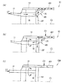
図16(a)〜(c)はフロアトンネルの作用図である。(a)は実施例のフロアトンネル15を左側方から見た構成を示す。(b)は実施例のフロアトンネル15を左上方から見た構成を示す。(c)は比較例のフロアトンネル15Aを左上方から見た構成を示す。
Next, the operation of the
16A to 16C are operation diagrams of the floor tunnel. (A) shows the structure which looked at the
(c)に示す比較例のフロアトンネル15Aは、前半部だけをトンネル部141とし、トンネル部141の後端を概ね垂直にしたものである。トンネル部141の上面142はほぼ水平である。
上記図1に示す車体10の前面に衝突エネルギーが作用することで、車体10前部が塑性変形したときに、車体10前部に取付けられたサブフレーム44及びサブフレーム44に取付けられたエンジン45は後方へ移動する。この結果、後退した高位のエンジン45が図16(c)に示すフロアトンネル15Aの前上端68Aに当たることで、この前上端68に衝突エネルギーE1が作用する。また、後退した低位のサブフレーム44(図1参照)からフロアトンネル15Aの前下端69Aに衝突エネルギーE2が作用する。
The
When the collision energy acts on the front surface of the
このように、後退した高位のエンジン45と低位のサブフレーム44の両方から、フロアトンネル15に衝突エネルギーE1,E2が伝わる。この場合、前上端68Aに作用した衝突エネルギーE1をフロアトンネル15の後方へ効率良く伝えるようにするには、改良の余地がある。
Thus, the collision energy E1, E2 is transmitted to the
これに対して、(a)及び(b)に示す実施例では、フロアトンネル15の上面63を前端部62から後方へ下り勾配となるように傾斜させたので、フロアトンネル15の前上端68に衝突エネルギーE1が作用したときに、この衝突エネルギーE1を下り勾配に合わせてフロアトンネル15の後下方へ効率良く伝え、さらに後方の第2・第3クロスメンバ22,23(図1参照)を介して車体後部に、効率良く伝えることができる。
On the other hand, in the embodiment shown in (a) and (b), since the
また、フロアトンネル15の前下端69に衝突エネルギーE2が作用したときには、そのまま衝突エネルギーE2をフロアトンネル15の後方へ効率良く伝え、さらに後方の第2・第3クロスメンバ22,23(図1参照)を介して車体後部に、効率良く伝えることができる。
しかも、衝突エネルギーE1,E2をフロアトンネル15から車体後部へ効率良く伝えるための部材を設ける必要がないので、車体重量を抑制することができる。
さらには、フロアトンネル15の後半部の高さを下げて車室を広くすることができ、この結果、車室の居住性を高めることができる。
Further, when the collision energy E2 acts on the front
In addition, since it is not necessary to provide a member for efficiently transmitting the collision energy E1, E2 from the
Furthermore, the height of the rear half of the
次に、上記構成のフロアトンネル15とフロアフレーム16との接合構造の作用を説明する。
図17(a),(b)はフロアトンネルとフロアフレームとの接合構造の作用図である。(a)は実施例のフロアトンネル15とフロアフレーム16との接合構造を右上方から見た構成を示す。(b)は比較例のフロアトンネル15とフロアフレーム16とを右上方から見た構成を示す。
Next, the operation of the joint structure between the
17 (a) and 17 (b) are operation diagrams of the joint structure between the floor tunnel and the floor frame. (A) shows the structure which looked at the junction structure of the
(b)に示す比較例の車体10Aは、フロアトンネル15に対してフロアフレーム16が分離し、フロアトンネル15に連なるフロアパネル51を左右のフロアフレーム16の上に重ねて接合したものである。
車体10Aに前方から衝突エネルギーEnが作用したときに、この衝突エネルギーEnはフロアフレーム16を介してフロアパネル51に分散しつつ伝わるとともに、フロアトンネル15からフロアパネル51に分散しつつ伝わる。このような場合に、フロアトンネル15の塑性変形量に対して、フロアフレーム16の後退量や塑性変形量を同一に設定することは困難である。このため、フロアトンネル15とフロアフレーム16との間で、フロアパネル51が変形し得る。
In the
When the collision energy En acts on the
これに対して、(a)に示す実施例では、フロアトンネル15の前部側部にフロアフレーム16の前部側部を直接に接合したので、フロアトンネル15とフロアフレーム16との間の前後方向の荷重を相互に分散し合うとともに、フロアトンネル15とフロアフレーム16との間で互いに強度や剛性を補完し合うことができる。
On the other hand, in the embodiment shown in (a), the front side of the
従って、車体10に前方から衝突エネルギーEnが作用したときに、フロアトンネル15に作用した衝突エネルギーEnをフロアトンネル15からフロアフレーム16に直接に伝えて分散させるることができる。また、フロアフレーム16に作用した衝突エネルギーEnをフロアフレーム16からフロアトンネル15に直接に伝えて分散させることができる。そして、フロアトンネル15とフロアフレーム16との間の前後の位置ずれを抑制することができる。この結果、フロアトンネル15とフロアフレーム16との間で、フロアパネル51の変形を抑制することができる。フロアパネル51の変形を抑制することによって、フロアトンネル15やフロアフレーム16に対するフロアパネル51の接合状態を確保することができる。
しかも、フロアトンネル15の前部側部とフロアフレーム16の前部側部とを直接に接合しただけの構成なので、新たな接合部材を設ける必要がなく、車体10の構成が簡単であり、車体10の重量を抑制することができる。
Therefore, when the collision energy En acts on the
Moreover, since the front side portion of the
次に、上記構成の三角状接合部85の作用を説明する。
図18(a)〜(c)は車体の作用図である。(a)は実施例の車体10に車体前方から衝突エネルギーEfが作用した状態を上方から見た図である。(b)は実施例の車体10に車体側方から衝突エネルギーEsが作用した状態を上方から見た図である。(c)は比較例の車体10Bに車体前方の衝突エネルギーEf及び車体側方の衝突エネルギーEsfが作用した状態を上方から見た図である。
Next, the operation of the triangular joint 85 having the above configuration will be described.
18A to 18C are operation diagrams of the vehicle body. (A) is the figure which looked at the state which the collision energy Ef acted on the
(c)に示す比較例の車体10Bは、車幅中心CLから左右両側方にフロアフレーム16(一方だけを示す。以下同じ。)及びサイドシル13をこの順に並列に設け、左右のサイドシル13間にクロスメンバ151を掛け渡し、クロスメンバ151にフロアフレーム16の後端を接合し、フロアフレーム16の前端から前方へフロントサイドフレーム11を延ばしたものである。
The
車体10Bの前方から作用した衝突エネルギーEfを、フロントサイドフレーム11からフロアフレーム16を介してクロスメンバ151に伝えることができる。しかし、クロスメンバ151から、これと直交するサイドシル13に衝突エネルギーEfを効率良く分散させるには、改良の余地がある。
一方、車体10Bの側方から作用した衝突エネルギーEsを、サイドシル13からクロスメンバ151に伝えることができる。しかし、クロスメンバ151から、これと直交するフロアフレーム16に衝突エネルギーEsを効率良く分散させるには、改良の余地がある。
The collision energy Ef applied from the front of the
On the other hand, the collision energy Es acting from the side of the
これに対して、(a),(b)に示す実施例では、サイドシル13とフロアフレーム16と第2クロスメンバ22との間の接合部分を、平面視略三角形状の接合構造、すなわち三角状接合部85としたものである。三角状接合部85を設けたことにより、サイドシル13とフロアフレーム16と第2クロスメンバ22との間で、互いに強度や剛性を補完し合うことができる。
On the other hand, in the embodiment shown in (a) and (b), the joint portion between the
(a)に示すように、車体10前方から作用した衝突エネルギーEfを、フロントサイドフレーム11からフロアフレーム16を介して三角状接合部85に伝え、さらに、この三角状接合部85から第2クロスメンバ22及びサイドシル13に効率良く分散させることができる。
また、(b)に示すように、車体10側方から作用した衝突エネルギーEsを、サイドシル13から三角状接合部85に伝え、さらに、この三角状接合部85からフロアフレーム16及び第2クロスメンバ22に効率良く分散させることができる。
As shown to (a), the collision energy Ef which acted from the front of the
Further, as shown in (b), the collision energy Es acting from the side of the
このように、車体10前方からの衝突エネルギーEf及び車体10側方からの衝突エネルギーEsの両方を、車体10全体に効率良く十分に分散させることができる。この結果、車体10全体で衝突エネルギーEf,Esを十分に吸収することができるので、車体10による衝突エネルギーEf,Esの吸収性能を高めることができる。しかも、車体10の各部材を大型にしたり、各部材を補強する新たな補強部材を設ける必要はない。このため、車体10の重量を抑制することができるとともに、車室内のスペースを十分に確保することができる。
Thus, both the collision energy Ef from the front of the
また、(b)に示すように、走行中には前輪からの振動が車体10前部を介してフロアフレーム16に伝わる。この振動の方向は、フロアフレーム16をねじる方向が主である。
これに対して実施例では、サイドシル13とフロアフレーム16の後端部との接合部分よりも前の位置において、左右のサイドシル13間に第2クロスメンバ22を掛け渡し、この第2クロスメンバ22にフロアフレーム16をも接合したので、その分、フロアフレーム16の長さを小さくすることができる。しかも、フロアフレーム16の後端を強固な三角状接合部85にて接合したものである。従って、フロアフレーム16のねじり方向の振動を低減することができる。
Further, as shown in (b), vibrations from the front wheels are transmitted to the
On the other hand, in the embodiment, the
本発明の車体構造は、車体前後に延びるフロアフレーム16,16を備えた自動車等の車両に好適である。 The vehicle body structure of the present invention is suitable for a vehicle such as an automobile provided with floor frames 16, 16 extending in the longitudinal direction of the vehicle body.
10…車体、11…フロントサイドフレーム、13…サイドシル、15…フロアトンネル、16…フロアフレーム、22…クロスメンバ(第2クロスメンバ)、75…フロアフレームの後端部、85…三角状接合部、CL…車体中心。
DESCRIPTION OF
Claims (1)
前記車体構造は、前記左右のサイドシルの長手途中に前記左右の上方開口且つコ字状のフロアフレームの後端部を前記左右のサイドシル側に湾曲させて接合し、それらの接合部分よりも前の位置で且つ接合部分の近傍で左右のサイドシル間に下方開口且つコ字状のクロスメンバを掛け渡し、このクロスメンバにフロアパネルを挟んで前記左右のフロアフレームをも接合することで、左のサイドシルと左のフロアフレームとクロスメンバとの間の接合部分を平面視略三角形状の接合構造とするともに、右のサイドシルと右のフロアフレームとクロスメンバとの間の接合部分を平面視略三角形状の接合構造としてなり、
前記フロアフレームの後端部は、前記左右のサイドシルに向けて末広がり形状に形成したことを特徴とする車体構造。 In a vehicle body structure in which a floor frame extending in the front-rear direction of the vehicle body and a side sill extending in the front-rear direction of the vehicle body are provided in parallel in this order from the vehicle width center to the left and right sides, and the left and right front side frames extend forward from the front ends of the left and right floor frames
The vehicle body structure is formed by joining the left and right upper openings and a U-shaped floor frame with the rear end of the left and right side sills curved in the middle of the left and right side sills, and joining the left and right side sills . At the position and in the vicinity of the joint part, a lower opening and a U-shaped cross member are spanned between the left and right side sills, and the left and right floor sills are joined by sandwiching the floor panel between the cross members. plan view a triangular shape the interface between the bonding portion and the bonding structure of the plan view triangle Then monitor, with the right side sill and the right floor frame and the cross member between the left floor frame and the cross member It becomes as a junction structure,
A vehicle body structure characterized in that a rear end portion of the floor frame is formed in a divergent shape toward the left and right side sills .
Priority Applications (3)
| Application Number | Priority Date | Filing Date | Title |
|---|---|---|---|
| JP2003356981A JP3962003B2 (en) | 2003-10-16 | 2003-10-16 | Body structure |
| US10/962,695 US6926352B2 (en) | 2003-10-16 | 2004-10-12 | Vehicle body structure |
| CN200410083739.XA CN1608922A (en) | 2003-10-16 | 2004-10-14 | Structure of vehicle body |
Applications Claiming Priority (1)
| Application Number | Priority Date | Filing Date | Title |
|---|---|---|---|
| JP2003356981A JP3962003B2 (en) | 2003-10-16 | 2003-10-16 | Body structure |
Publications (2)
| Publication Number | Publication Date |
|---|---|
| JP2005119492A JP2005119492A (en) | 2005-05-12 |
| JP3962003B2 true JP3962003B2 (en) | 2007-08-22 |
Family
ID=34509815
Family Applications (1)
| Application Number | Title | Priority Date | Filing Date |
|---|---|---|---|
| JP2003356981A Expired - Fee Related JP3962003B2 (en) | 2003-10-16 | 2003-10-16 | Body structure |
Country Status (3)
| Country | Link |
|---|---|
| US (1) | US6926352B2 (en) |
| JP (1) | JP3962003B2 (en) |
| CN (1) | CN1608922A (en) |
Families Citing this family (51)
| Publication number | Priority date | Publication date | Assignee | Title |
|---|---|---|---|---|
| DE112004000173T5 (en) * | 2003-01-23 | 2006-02-23 | Fukumoto, Toshihiro | Vehicle with free-formed floor surface |
| DE602005003737T2 (en) * | 2004-09-29 | 2008-12-11 | Mazda Motor Corp. | Vehicle underbody or substructure or structure |
| US7380830B2 (en) * | 2005-02-03 | 2008-06-03 | Honda Motor Co., Ltd. | Vehicle front body structure |
| JP4359264B2 (en) * | 2005-06-03 | 2009-11-04 | 本田技研工業株式会社 | Car seat mounting structure |
| JP4400548B2 (en) | 2005-11-02 | 2010-01-20 | トヨタ自動車株式会社 | Lower body structure |
| JP4801462B2 (en) | 2006-02-16 | 2011-10-26 | 本田技研工業株式会社 | Lower body structure |
| JP4857976B2 (en) * | 2006-07-14 | 2012-01-18 | 日産自動車株式会社 | Vehicle floor structure |
| CN101117135B (en) * | 2006-07-31 | 2012-09-05 | 比亚迪股份有限公司 | Electric automobile frame |
| JP4297152B2 (en) * | 2006-10-06 | 2009-07-15 | トヨタ自動車株式会社 | Vehicle front structure |
| FR2914616B1 (en) * | 2007-04-04 | 2009-05-29 | Renault Sas | MOTOR VEHICLE RELIEF |
| JP4612014B2 (en) * | 2007-04-20 | 2011-01-12 | 本田技研工業株式会社 | Body floor structure |
| BRPI0810527A2 (en) | 2007-04-20 | 2014-10-21 | Honda Motor Co Ltd | VEHICLE FLOOR STRUCTURE |
| JP4459984B2 (en) * | 2007-06-19 | 2010-04-28 | 本田技研工業株式会社 | Body floor structure |
| JP4558019B2 (en) * | 2007-08-06 | 2010-10-06 | 本田技研工業株式会社 | Body floor structure |
| DE602008001029D1 (en) | 2007-06-19 | 2010-06-02 | Honda Motor Co Ltd | Vehicle body floor structure |
| JP4900095B2 (en) * | 2007-07-06 | 2012-03-21 | 日産自動車株式会社 | Auto body floor structure |
| US7469957B1 (en) | 2007-12-07 | 2008-12-30 | Honda Motor Co., Ltd. | Front floor frame |
| US7896397B2 (en) * | 2007-12-27 | 2011-03-01 | Honda Motor Co., Ltd. | Single piece side-sill-garnish and mudguard |
| JP5369696B2 (en) * | 2009-01-20 | 2013-12-18 | マツダ株式会社 | Lower body structure of the vehicle |
| CN102001362B (en) * | 2009-08-27 | 2013-01-02 | 本田技研工业株式会社 | Vehicle body structure |
| JP5280550B2 (en) * | 2009-12-16 | 2013-09-04 | 本田技研工業株式会社 | Body panel joint structure |
| US8801082B2 (en) * | 2010-06-24 | 2014-08-12 | Honda Motor Co., Ltd. | Vehicle body front part structure |
| CN102019961B (en) * | 2010-12-01 | 2014-03-12 | 奇瑞汽车股份有限公司 | Automobile body structure on lower part of automobile with moveable top |
| DE102011103090A1 (en) * | 2011-05-25 | 2012-11-29 | Thyssenkrupp Steel Europe Ag | Vehicle body and its use |
| CN103717482B (en) * | 2011-08-02 | 2016-03-09 | 本田技研工业株式会社 | Structure of rear vehicle |
| JP6019735B2 (en) * | 2011-08-29 | 2016-11-02 | 日産自動車株式会社 | Body structure and method for manufacturing body |
| CN103158788B (en) * | 2011-12-09 | 2016-03-16 | 北汽福田汽车股份有限公司 | Automobile front floor and automobile |
| JP5670307B2 (en) * | 2011-12-15 | 2015-02-18 | 本田技研工業株式会社 | Car floor structure |
| JP5509241B2 (en) * | 2012-03-26 | 2014-06-04 | 本田技研工業株式会社 | Auto body front structure |
| JP5949042B2 (en) * | 2012-03-28 | 2016-07-06 | マツダ株式会社 | Front subframe structure |
| FR2989053B1 (en) | 2012-04-05 | 2014-03-21 | Renault Sa | CHASSIS OF A MOTOR VEHICLE COMPRISING MEANS FOR ABSORPTION OF A FRONTAL SHOCK |
| US8632121B1 (en) * | 2012-11-14 | 2014-01-21 | Ford Global Technologies, Llc | Pole impact protection system |
| DE102013004793A1 (en) * | 2013-03-20 | 2014-09-25 | GM Global Technology Operations LLC (n. d. Ges. d. Staates Delaware) | Floor structure of a motor vehicle body |
| DE102013011528A1 (en) * | 2013-07-10 | 2015-01-15 | Audi Ag | Support structure for a motor vehicle |
| US9248860B2 (en) * | 2013-07-22 | 2016-02-02 | GM Global Technology Operations LLC | Center tunnel integrated truss architecture |
| DE102014110042B4 (en) | 2013-07-22 | 2024-07-18 | GM Global Technology Operations LLC (n. d. Gesetzen des Staates Delaware) | VEHICLE WITH A CENTRAL TUNNEL ASSEMBLY |
| JP2017077736A (en) * | 2014-03-07 | 2017-04-27 | 日産自動車株式会社 | Vehicle body structure |
| JP6011583B2 (en) * | 2014-07-04 | 2016-10-19 | トヨタ自動車株式会社 | Vehicle lower structure |
| CN105313988A (en) * | 2014-07-31 | 2016-02-10 | 长城汽车股份有限公司 | Vehicle body for vehicle and vehicle provided with vehicle body |
| FR3024422B1 (en) * | 2014-08-04 | 2016-08-26 | Peugeot Citroen Automobiles Sa | CROSS FLOOR COMPRISING A DEFORMABLE PORTION IN COMPRESSION |
| CN104309693B (en) * | 2014-09-29 | 2017-06-09 | 上汽通用五菱汽车股份有限公司 | A kind of front-engine rear-drive vehicle body |
| WO2016076315A1 (en) * | 2014-11-10 | 2016-05-19 | 新日鐵住金株式会社 | T-joint structure |
| JP6119720B2 (en) | 2014-11-13 | 2017-04-26 | トヨタ自動車株式会社 | Vehicle lower structure |
| JP6236046B2 (en) * | 2015-09-17 | 2017-11-22 | 本田技研工業株式会社 | Body structure |
| JP6600873B2 (en) * | 2016-02-19 | 2019-11-06 | 本田技研工業株式会社 | Body structure |
| JP6900882B2 (en) * | 2017-11-20 | 2021-07-07 | トヨタ自動車株式会社 | Vehicle undercarriage |
| JP6734334B2 (en) | 2018-09-14 | 2020-08-05 | 本田技研工業株式会社 | Vehicle substructure |
| DE102018126597A1 (en) * | 2018-10-25 | 2020-04-30 | Bayerische Motoren Werke Aktiengesellschaft | Motor vehicle |
| JP7310458B2 (en) * | 2019-09-03 | 2023-07-19 | マツダ株式会社 | Vehicle front body structure |
| JP7247853B2 (en) * | 2019-10-16 | 2023-03-29 | マツダ株式会社 | car body structure |
| CN111267959B (en) * | 2020-03-11 | 2020-12-22 | 河南工学院 | Vibration-dampening bodies for improved automotive NVH performance |
Family Cites Families (7)
| Publication number | Priority date | Publication date | Assignee | Title |
|---|---|---|---|---|
| DE1119132B (en) * | 1959-08-28 | 1961-12-07 | Daimler Benz Ag | Frame floor system for motor vehicles |
| DE2527385C3 (en) * | 1975-06-19 | 1982-10-07 | Daimler-Benz Ag, 7000 Stuttgart | Floor pan for self-supporting bodies of motor vehicles |
| JPS58128970A (en) * | 1982-01-27 | 1983-08-01 | Mazda Motor Corp | Construction of car body |
| JPH0611901Y2 (en) * | 1986-07-03 | 1994-03-30 | フオルクスウア−ゲン・アクチエンゲゼルシヤフト | Automotive floor materials |
| DE3905650C2 (en) * | 1989-02-24 | 1995-02-09 | Daimler Benz Ag | Self-supporting vehicle body |
| DE3925990A1 (en) * | 1989-08-05 | 1991-02-07 | Daimler Benz Ag | ASSEMBLY FOR THE FRONT AND REAR AREAS OF A MOTOR VEHICLE |
| JPH07187019A (en) | 1993-12-27 | 1995-07-25 | Nissan Motor Co Ltd | Vehicle body structure of automobile |
-
2003
- 2003-10-16 JP JP2003356981A patent/JP3962003B2/en not_active Expired - Fee Related
-
2004
- 2004-10-12 US US10/962,695 patent/US6926352B2/en not_active Expired - Fee Related
- 2004-10-14 CN CN200410083739.XA patent/CN1608922A/en active Pending
Also Published As
| Publication number | Publication date |
|---|---|
| US20050082877A1 (en) | 2005-04-21 |
| CN1608922A (en) | 2005-04-27 |
| US6926352B2 (en) | 2005-08-09 |
| JP2005119492A (en) | 2005-05-12 |
Similar Documents
| Publication | Publication Date | Title |
|---|---|---|
| JP3962003B2 (en) | Body structure | |
| JP3976198B2 (en) | Body front structure | |
| JP4677025B2 (en) | Body front structure | |
| JP6041054B2 (en) | Body front structure | |
| US7104596B2 (en) | Vehicle body structure | |
| JP5927695B2 (en) | Lower body structure | |
| JP2003300484A (en) | Body structure | |
| JPWO2013018415A1 (en) | Body side structure | |
| JP2019202747A (en) | Vehicle body lower part structure | |
| JP2008230460A (en) | Lower body structure of vehicle | |
| WO2013077085A1 (en) | Vehicle body superstructure | |
| CN110077469A (en) | Body construction | |
| JP3976199B2 (en) | Body structure | |
| JP2003237636A (en) | Car-body front structure | |
| JP2008230459A (en) | Lower body structure of vehicle | |
| JP2014031106A (en) | Vehicle body front part structure | |
| JP3889741B2 (en) | Body structure | |
| JP6176228B2 (en) | Front body structure of the vehicle | |
| JP2013216201A (en) | Automobile cfrp cabin | |
| JP5150452B2 (en) | Body front structure | |
| JP2009040337A (en) | Front body structure of automobile | |
| JP6520161B2 (en) | Vehicle side structure | |
| JP4123012B2 (en) | Body front structure | |
| JPH0752788Y2 (en) | Car front pillar stiffening structure | |
| JP5848628B2 (en) | Car body rear structure |
Legal Events
| Date | Code | Title | Description |
|---|---|---|---|
| A977 | Report on retrieval |
Free format text: JAPANESE INTERMEDIATE CODE: A971007 Effective date: 20060919 |
|
| A131 | Notification of reasons for refusal |
Free format text: JAPANESE INTERMEDIATE CODE: A131 Effective date: 20061003 |
|
| A521 | Request for written amendment filed |
Free format text: JAPANESE INTERMEDIATE CODE: A523 Effective date: 20061114 |
|
| TRDD | Decision of grant or rejection written | ||
| A01 | Written decision to grant a patent or to grant a registration (utility model) |
Free format text: JAPANESE INTERMEDIATE CODE: A01 Effective date: 20070515 |
|
| A61 | First payment of annual fees (during grant procedure) |
Free format text: JAPANESE INTERMEDIATE CODE: A61 Effective date: 20070517 |
|
| R150 | Certificate of patent or registration of utility model |
Free format text: JAPANESE INTERMEDIATE CODE: R150 |
|
| FPAY | Renewal fee payment (event date is renewal date of database) |
Free format text: PAYMENT UNTIL: 20110525 Year of fee payment: 4 |
|
| FPAY | Renewal fee payment (event date is renewal date of database) |
Free format text: PAYMENT UNTIL: 20110525 Year of fee payment: 4 |
|
| FPAY | Renewal fee payment (event date is renewal date of database) |
Free format text: PAYMENT UNTIL: 20130525 Year of fee payment: 6 |
|
| FPAY | Renewal fee payment (event date is renewal date of database) |
Free format text: PAYMENT UNTIL: 20130525 Year of fee payment: 6 |
|
| FPAY | Renewal fee payment (event date is renewal date of database) |
Free format text: PAYMENT UNTIL: 20140525 Year of fee payment: 7 |
|
| LAPS | Cancellation because of no payment of annual fees |