JP3960005B2 - Rotation support device for wheels - Google Patents
Rotation support device for wheels Download PDFInfo
- Publication number
- JP3960005B2 JP3960005B2 JP2001323856A JP2001323856A JP3960005B2 JP 3960005 B2 JP3960005 B2 JP 3960005B2 JP 2001323856 A JP2001323856 A JP 2001323856A JP 2001323856 A JP2001323856 A JP 2001323856A JP 3960005 B2 JP3960005 B2 JP 3960005B2
- Authority
- JP
- Japan
- Prior art keywords
- ring
- peripheral surface
- support hole
- wheel
- retaining ring
- Prior art date
- Legal status (The legal status is an assumption and is not a legal conclusion. Google has not performed a legal analysis and makes no representation as to the accuracy of the status listed.)
- Expired - Fee Related
Links
Images


Classifications
-
- F—MECHANICAL ENGINEERING; LIGHTING; HEATING; WEAPONS; BLASTING
- F16—ENGINEERING ELEMENTS AND UNITS; GENERAL MEASURES FOR PRODUCING AND MAINTAINING EFFECTIVE FUNCTIONING OF MACHINES OR INSTALLATIONS; THERMAL INSULATION IN GENERAL
- F16C—SHAFTS; FLEXIBLE SHAFTS; ELEMENTS OR CRANKSHAFT MECHANISMS; ROTARY BODIES OTHER THAN GEARING ELEMENTS; BEARINGS
- F16C35/00—Rigid support of bearing units; Housings, e.g. caps, covers
- F16C35/04—Rigid support of bearing units; Housings, e.g. caps, covers in the case of ball or roller bearings
- F16C35/06—Mounting or dismounting of ball or roller bearings; Fixing them onto shaft or in housing
- F16C35/067—Fixing them in a housing
-
- F—MECHANICAL ENGINEERING; LIGHTING; HEATING; WEAPONS; BLASTING
- F16—ENGINEERING ELEMENTS AND UNITS; GENERAL MEASURES FOR PRODUCING AND MAINTAINING EFFECTIVE FUNCTIONING OF MACHINES OR INSTALLATIONS; THERMAL INSULATION IN GENERAL
- F16B—DEVICES FOR FASTENING OR SECURING CONSTRUCTIONAL ELEMENTS OR MACHINE PARTS TOGETHER, e.g. NAILS, BOLTS, CIRCLIPS, CLAMPS, CLIPS OR WEDGES; JOINTS OR JOINTING
- F16B21/00—Means for preventing relative axial movement of a pin, spigot, shaft or the like and a member surrounding it; Stud-and-socket releasable fastenings
- F16B21/06—Releasable fastening devices with snap-action
- F16B21/08—Releasable fastening devices with snap-action in which the stud, pin, or spigot has a resilient part
-
- F—MECHANICAL ENGINEERING; LIGHTING; HEATING; WEAPONS; BLASTING
- F16—ENGINEERING ELEMENTS AND UNITS; GENERAL MEASURES FOR PRODUCING AND MAINTAINING EFFECTIVE FUNCTIONING OF MACHINES OR INSTALLATIONS; THERMAL INSULATION IN GENERAL
- F16C—SHAFTS; FLEXIBLE SHAFTS; ELEMENTS OR CRANKSHAFT MECHANISMS; ROTARY BODIES OTHER THAN GEARING ELEMENTS; BEARINGS
- F16C19/00—Bearings with rolling contact, for exclusively rotary movement
- F16C19/02—Bearings with rolling contact, for exclusively rotary movement with bearing balls essentially of the same size in one or more circular rows
- F16C19/14—Bearings with rolling contact, for exclusively rotary movement with bearing balls essentially of the same size in one or more circular rows for both radial and axial load
- F16C19/18—Bearings with rolling contact, for exclusively rotary movement with bearing balls essentially of the same size in one or more circular rows for both radial and axial load with two or more rows of balls
- F16C19/181—Bearings with rolling contact, for exclusively rotary movement with bearing balls essentially of the same size in one or more circular rows for both radial and axial load with two or more rows of balls with angular contact
- F16C19/183—Bearings with rolling contact, for exclusively rotary movement with bearing balls essentially of the same size in one or more circular rows for both radial and axial load with two or more rows of balls with angular contact with two rows at opposite angles
- F16C19/184—Bearings with rolling contact, for exclusively rotary movement with bearing balls essentially of the same size in one or more circular rows for both radial and axial load with two or more rows of balls with angular contact with two rows at opposite angles in O-arrangement
-
- F—MECHANICAL ENGINEERING; LIGHTING; HEATING; WEAPONS; BLASTING
- F16—ENGINEERING ELEMENTS AND UNITS; GENERAL MEASURES FOR PRODUCING AND MAINTAINING EFFECTIVE FUNCTIONING OF MACHINES OR INSTALLATIONS; THERMAL INSULATION IN GENERAL
- F16C—SHAFTS; FLEXIBLE SHAFTS; ELEMENTS OR CRANKSHAFT MECHANISMS; ROTARY BODIES OTHER THAN GEARING ELEMENTS; BEARINGS
- F16C2326/00—Articles relating to transporting
- F16C2326/01—Parts of vehicles in general
- F16C2326/02—Wheel hubs or castors
Landscapes
- Engineering & Computer Science (AREA)
- General Engineering & Computer Science (AREA)
- Mechanical Engineering (AREA)
- Rolling Contact Bearings (AREA)
- Hand Tools For Fitting Together And Separating, Or Other Hand Tools (AREA)
- Snaps, Bayonet Connections, Set Pins, And Snap Rings (AREA)
Description
【0001】
【発明の属する技術分野】
この発明は、車輪を支持する為の車輪用軸受ユニットと、自動車の独立懸架式サスペンションの一部を構成する支持部材とを組み合わせて、懸架装置に対して車輪を回転自在に支持する為の車輪用回転支持装置の改良に関する。
【0002】
【従来の技術】
車輪を懸架装置に対して回転自在に支持する為に、外輪と内輪とを転動体を介して回転自在に組み合わせた車輪用軸受ユニットが、各種使用されている。又、懸架装置の一種である独立懸架式サスペンションに対して、車輪を回転自在に支持する為に、この独立懸架式サスペンションの一部を構成するナックルに設けた支持孔に、上記車輪用軸受ユニットを構成する外輪の一部を内嵌して、この外輪と上記支持部材とを複数のボルトにより結合した車輪用回転支持装置も、従来から広く使用されている。図7は、この様な車輪用回転支持装置のうち、独立懸架式サスペンションに駆動輪を支持すると共に、この駆動輪を回転駆動する為の車輪駆動用の車輪用軸受ユニット1と、懸架装置を構成するナックル30とを組み合わせた車輪用回転支持装置の、一般的な構造を示している。
【0003】
このうちの車輪用軸受ユニット1は、外輪3の内径側にハブ4及び内輪5を、複数の転動体6、6を介して回転自在に支持して成る。このうちの外輪3は、その外周面に設けた第一の取付フランジ7により、懸架装置の一部を構成する支持部材である、ナックル30に結合固定した状態で、使用時にも回転しない。即ち、上記車輪用軸受ユニット1の使用時には、上記外輪3の軸方向内端(軸方向に関して内とは、自動車への組み付け状態で車両の幅方向中央側となる側で、図1、2、7の右側。本明細書全体で同じ。)部外周面に設けた円筒面状の嵌合部31を上記ナックル30に設けた支持孔32に内嵌する。そして、この状態で、上記ナックル30に設けた複数の通孔33にボルト34を挿通させ、これら各ボルト34の雄ねじ部を、上記第一の取付フランジ7に設けたねじ孔35に螺合・緊締する事により、上記車輪用軸受ユニット1を上記ナックル30に対し結合している。又、上記外輪3の内周面には1対の外輪軌道8、8を設けて、この外輪3の内径側に、それぞれが回転部材36を構成する、ハブ4及び内輪5を、この外輪3と同心に、回転自在に支持している。
【0004】
このうちのハブ4は、外周面の軸方向外端(軸方向に関して外とは、自動車への組み付け状態で車両の幅方向外側となる側で、図1、2、7の左側。本明細書全体で同じ。)寄り部分に、車輪を支持する為の第二の取付フランジ9を設けている。又、上記ハブ4の外周面の中間部に第一の内輪軌道10を形成し、同じく軸方向内端部に形成した小径段部11に、その外周面に第二の内輪軌道12を形成した上記内輪5を外嵌固定している。又、上記ハブ4の中心部には、スプライン孔13を設けている。
【0005】
一方、前記車輪用軸受ユニット1には等速ジョイント2を組み合わせている。この等速ジョイント2は、等速ジョイント用外輪14と、等速ジョイント用内輪15と、複数のボール16、16と、スプライン軸17とを備える。このうちの等速ジョイント用外輪14とスプライン軸17とが、駆動軸部材18を構成する。即ち、このスプライン軸17はこの駆動軸部材18の軸方向外半部に設けたもので、上記スプライン孔13と係合自在であり、上記等速ジョイント用外輪14は、上記駆動軸部材18の軸方向内半部に設けている。この等速ジョイント用外輪14の内周面の円周方向複数個所には外側係合溝19、19を、それぞれこの円周方向に対し直角方向に形成している。又、上記等速ジョイント用内輪15は、中心部に第二のスプライン孔20を、その外周面で上記各外側係合溝19、19と整合する部分に内側係合溝21、21を、それぞれ円周方向に対し直角方向に形成している。そして、これら各内側係合溝21、21と上記各外側係合溝19、19との間に上記各ボール16、16を、保持器22により保持した状態で、これら各係合溝21、19に沿う転動自在に設けている。
【0006】
上述の様な等速ジョイント2と前述の様な車輪用軸受ユニット1とを組み合わせるには、上記スプライン軸17を上記ハブ4のスプライン孔13に、軸方向に関して内側から外側に向け挿通する。そして、上記スプライン軸17の軸方向外端部で上記ハブ4の外端面から突出した部分に設けた雄ねじ部23にナット24を螺合し、更に緊締する事により、互いに結合固定する。この状態で、前記内輪5の内端面は上記等速ジョイント用外輪14の外端面に当接するので、この内輪5が前記小径段部11から抜け出る方向に変位する事はない。同時に、前記各転動体6、6に適正な予圧が付与される。
【0007】
更に、自動車の懸架装置への組み付け状態では、前記等速ジョイント用内輪15の中心部に設けた第二のスプライン孔20に、駆動軸25の軸方向外端部に設けた雄スプライン部26をスプライン係合させる。そして、この雄スプライン部26の軸方向外端部外周面に全周に亙って形成した係止溝27に係止した止め輪28を、上記第二のスプライン孔20の軸方向外端開口周縁部に形成した係止段部29に係合させて、上記雄スプライン部26が上記第二のスプライン孔20から抜け出る事を防止する。尚、上記駆動軸25の軸方向内端部は、図示しないデファレンシャルギヤの出力軸部に設けた、やはり図示しないトリポード型等速ジョイントのトラニオンの中心部に結合固定する。従って、自動車の走行時に上記駆動軸25は、等速回転する。
【0008】
又、米国特許明細書第5,927,867号には、車輪用軸受ユニットを構成する外輪の外周面を、(ナックルに固定する為の取付フランジを形成しない)単なる円筒面とすると共に、上記外輪とナックルとを環状部材により結合した構造が記載されている。この環状部材は、断面略L字形で全体を円環状に形成している。又、この環状部材を構成する筒部の円周方向一部に突起部を、この筒部の外周面から傾斜して突出する状態で形成している。又、上記ナックルの支持孔の軸方向一端部内周面に溝部を形成している。そして、この支持孔に上記外輪を挿入すると共に、この支持孔の軸方向他端部内周面に設けた内向鍔部の側面に上記外輪の軸方向他端面を突き当てている。そして、この外輪の軸方向一端部外周面に環状部材を外嵌すると共に、上記突起部の先端を、上記溝部の両側面のうちで軸方向他側に向いた側面に突き当てている。この為、上記外輪は、上記支持孔の内側から抜け出る方向に変位する事が阻止される。この様な米国特許明細書第5,927,867号に記載された従来構造の第2例の場合、上記外輪とナックルとを結合する為に、複数本のボルトを使用する必要がなくなる。
【0009】
又、特開2001−105806号公報には、ナックルと、車輪用軸受ユニットを構成する外輪とを、弾性材製で有端形状のクリップにより結合した構造が記載されている。この様な従来構造の第3例の場合、ナックルの支持孔の内周面の周方向に形成された外側係合溝と、外輪の外周面の周方向に形成された内側係合溝とを備える。そして、上記外輪を上記ナックルに結合する際に、上記クリップを上記内側係合溝に装着すると共に、このクリップの直径を弾性的に縮めた状態で、上記支持孔に上記外輪を挿入する。この挿入作業に伴って、上記クリップが上記外側係合溝に整合した状態では、このクリップの直径が弾性復帰する為、このクリップが上記外側係合溝と内側係合溝との間に掛け渡されて、上記外輪が上記支持孔から抜け出る方向に変位する事が阻止される。この様な上記特開2001−105806号公報に記載された従来構造の第3例の場合も、外輪とナックルとを結合する為に、複数本のボルトを使用する必要がなくなる。
【0010】
【発明が解決しようとする課題】
前述した米国特許明細書第5,927,867号に記載された従来構造の第2例、及び、上述した特開2001−105806号公報に記載された従来構造の第3例の何れも場合も、外輪とナックルとを結合する為に、複数本のボルトを使用する必要がなくなる。但し、これら各従来構造の場合、使用時に、万が一、外輪軌道又は内輪軌道の剥離等の軸受異常が生じて、車輪用軸受ユニットを点検・修理する必要が生じた場合に、この点検・修理に要するコストが嵩んでしまう。即ち、この点検・修理の為には、ナックルに設けた支持孔から車輪用軸受ユニットを取り外す必要があるが、上述した従来構造の第2、3例の何れの場合も、この取り外し作業を容易に行なえる様にする為の考慮をしていない。この為、この様な構造で上記取り外し作業を行う場合には、プーラー等の特殊な工具により、上記支持孔から上記外輪を大きな力で引っ張り出す必要があるが、環状部材やクリップを破損せずに上記取り外し作業を行なうのは難しい。従って、上記車輪用軸受ユニットの点検・修理の際に、上記環状部材やクリップを交換する必要が生じて、点検・修理に要するコストが嵩む原因となる。又、上記支持孔から上記外輪を抜き出す際に、上記ナックルの支持孔の内周面に形成した溝部又は外側係合溝や、外輪の外周面に形成した内側係合溝に、上記環状部材又はクリップから大きな力が加わる為、上記ナックルや外輪の一部が破損する可能性がある。この場合には、このナックルや外輪を交換する必要も生じて、上記点検・修理に要するコストが、更に嵩む原因となる。
本発明の車輪用回転支持装置は、この様な事情に鑑みて、外輪と支持部材とを止め輪により結合する構造で、車輪用軸受ユニットの点検・修理に要するコストを低減すべく発明したものである。
【0011】
【課題を解決するための手段】
本発明の車輪用回転支持装置は、前述の図7に示した従来構造の第1例と同様に、懸架装置を構成して車輪を支持する支持部材と、この支持部材に設けられた支持孔の内径側に支持された車輪用軸受ユニットとを備える。
そして、このうちの車輪用軸受ユニットは、内周面に外輪軌道を、外周面に上記支持孔に内嵌する為の嵌合部を、それぞれ有し、使用時にも回転しない外輪と、外周面の一端寄り部分に車輪を支持する為の取付フランジを、同じく中間部に上記外輪軌道と対向する内輪軌道を、それぞれ有し、使用時に回転する回転部材と、この内輪軌道と上記外輪軌道との間に転動自在に設けられた複数個の転動体とを備える。
【0012】
特に、本発明の車輪用回転支持装置に於いては、上記嵌合部の外周面の軸方向中間部に周方向に設けられた内側係合溝と、上記支持孔の内周面の軸方向中間部に周方向に設けられた外側係合溝と、弾性材製で全体を欠円環状に形成され、この外側係合溝と上記内側係合溝との間に掛け渡された止め輪と、上記支持孔の内周面の円周方向複数個所に、それぞれこの支持孔の内周面よりも径方向外方に凹んだ状態で、且つ、それぞれの軸方向内端がこの支持孔の軸方向内端開口に達し、それぞれの軸方向外端が上記外側係合溝よりも軸方向外方に迄達する状態で、上記支持孔の軸方向に設けられた複数の凹入部とを備える。そして、これら各凹入部内に進入させた治具の先端部を、これら各凹入部内に存在する上記止め輪の円周方向複数個所に係合させる事により、この止め輪の外径を、上記支持孔の内径以下に弾性的に縮小自在としている。
【0013】
【作用】
上述の様に構成する本発明の車輪用回転支持装置によれば、支持部材の支持孔の内周面に設けた外側係合溝と、外輪の嵌合部に設けた内側係合溝との間に止め輪を掛け渡している為、上記支持部材に上記外輪を結合する為に複数本のボルトを使用する必要がなくなり、組立作業の容易化によるコスト低減と、小型化及び軽量化とを図れる。又、上記外輪の外周面に、支持部材に固定する為の取付フランジを設ける必要がなくなる為、この外輪の外周面の形状を単純にできる。しかも、本発明の場合には、支持部材から車輪用軸受ユニットを取り外す作業を、容易に行なえる。又、この取り外し作業の際に、上記止め輪が破損する事を防止でき、この止め輪を再利用できる。更に、この取り外し作業の際に、この止め輪から上記ナックル及び外輪に大きな力が加わる事がなくなる為、このナックル及び外輪が破損する事も防止できる。従って、車輪用軸受ユニットの点検・修理に要するコストを低減できる。
【0014】
【発明の実施の形態】
図1〜5は、本発明の実施の形態の1例を示している。尚、本発明の特徴は、支持部材であるナックル30と、外輪3aとを止め輪44により結合する構造で、車輪用軸受ユニット1aの修理・交換に要するコストを低減すべく、上記外輪3aとナックル30との結合部の構造を工夫した点にある。本例に於いて、その他の部分の構造は、前述の図7に示した従来構造の第1例とほぼ同様であるから、重複する説明を省略若しくは簡略にし、以下、本発明の特徴部分並びに上記従来構造と異なる部分を中心に説明する。
【0015】
本発明の車輪用回転支持装置は、懸架装置を構成して車輪を支持する支持部材である、ナックル30と、このナックル30に設けた支持孔32の内径側に支持した車輪用軸受ユニット1aとを備える。この車輪用軸受ユニット1aは、外輪3aの内径側にハブ4a及び1対の内輪5a、5bを回転自在に支持している。即ち、本例の場合には、ハブ4aの軸方向内半部外周面に小径段部11を形成すると共に、この小径段部11に、それぞれの外周面に第一、第二の内輪軌道10、12を形成した1対の内輪5a、5bを外嵌している。そして、上記ハブ4aの内端部で、これら1対の内輪5a、5bのうち、軸方向内側(図1、2の右側)の内輪5bの軸方向内端面から突出した部分を直径方向外方にかしめ広げる事で形成したかしめ部37により、上記1対の内輪5a、5bを上記ハブ4aに対し固定している。本例の場合には、これら1対の内輪5a、5b及びハブ4aが、回転部材36aを構成している。そして、上記外輪3aの内周面に上記各内輪軌道10、12に対向する状態で形成した1対の外輪軌道8、8と、上記各内輪軌道10、12との間に、それぞれ複数ずつの転動体6、6を転動自在に設ける事により、上記外輪3aの内径側に上記ハブ4a及び1対の内輪5a、5bを回転自在に支持している。
【0016】
又、前記車輪用軸受ユニット1aは、等速ジョイント2aと組み合わせている。この為に、この等速ジョイント2aを構成する駆動軸部材18aに設けたスプライン軸17aの外端寄り部分外周面に内側係止溝39を、全周に亙って形成すると共に、上記スプライン孔13の外端部内周面でこの内側係止溝39と整合する位置に、外側係止溝40を、全周に亙って形成している。そして、これら内側、外側両係止溝39、40に、欠円環状の第二の止め輪38を掛け渡している。この第二の止め輪38は、ばね鋼、ステンレスばね鋼等の弾性材製の線材を曲げ形成する事により、略C字形の欠円環状に形成したもので、径を広げる方向の弾性を有する。この様な第二の止め輪38は、径を弾性的に広げた状態で、上記両係止溝39、40同士の間に掛け渡されて、上記スプライン軸17aが上記スプライン孔13から抜け出るのを防止する。
【0017】
又、本例の場合には、上記駆動軸部材18aを構成する等速ジョイント用外輪14の外端面と、上記ハブ4aの内端部に設けたかしめ部37の内端との間でシールリング41を、軸方向に弾性的に圧縮している。又、上記ハブ4aの外端部に形成した筒部42に、有底円筒状のキャップ43を内嵌固定している。そして、このキャップ43と上記シールリング41とにより、上記スプライン軸17aと上記スプライン孔13とのスプライン係合部に、雨水等の異物が進入する事を防止して、このスプライン係合部が錆び付く事を防止している。
【0018】
特に、本例の車輪用回転支持装置の場合には、前記ナックル30に設けた支持孔32の内周面と、前記車輪用軸受ユニット1aを構成する外輪3aの外周面との間に掛け渡した止め輪44により、上記ナックル30と車輪用軸受ユニット1aとの分離を防止している。即ち、本例の場合、上記外輪3aの外周面を、(上記ナックル30に固定する為の取付フランジを形成しない)単なる円筒面状の嵌合部31としている。又、この嵌合部31の軸方向中間部で、径方向に関する厚さが最も大きくなった部分(=内周面に外輪軌道8、8を形成した部分同士の間部分)に内側係合溝45を、全周に亙って形成している。そして、上記支持孔32の内周面の軸方向中間部で上記内側係合溝45と整合する位置に、外側係合溝46を、全周に亙って形成している。尚、上記嵌合部31の外径は、上記支持孔32の内径と同じか、この内径よりも僅かに小さくしている。
【0019】
更に、本例の場合、この支持孔32の軸方向内半部(図1、2の右半部)内周面の円周方向複数個所(図示の例では3個所)に、それぞれ凹入部47を形成している。これら各凹入部47は、上記支持孔32の内周面よりも径方向外方に凹んだ状態で設けられたもので、それぞれの軸方向内端が上記支持孔32の軸方向内端開口に達し、それぞれの軸方向外端が上記外側係合溝46よりも軸方向外方に迄達する。即ち、上記各凹入部47は、上記支持孔32の軸方向内端開口から上記外側係合溝46を越えた部分に亙り形成している。又、本例の場合には、上記支持孔32の軸方向外端部内周面に、軸方向に対する傾斜角度θ(図2)が10〜30度程度である、円すい凹面状のガイド面48を、全周に亙って形成している。
【0020】
そして、上記外輪3aを上記支持孔32に内嵌した状態で、この支持孔32の内周面に形成した外側係合溝46と、上記外輪3aの嵌合部31の外周面に形成した内側係合溝45との間に、図4に詳示する様な止め輪44を掛け渡している。この止め輪44は、SWRHの如き硬鋼線材、SWP−Bの如きピアノ線、SK−5の如き炭素工具鋼材等の弾性金属材製の線材を曲げ形成する事により、略C字形の欠円環状に形成したもので、組み付け状態で直径を広げる方向の弾力を有する。又、この止め輪44は、曲げ形成した後、焼き入れ処理を施して、硬化させている。この止め輪44の自由状態での外径D44は、上記外側係合溝46の溝底の直径d46(図2)よりも大きくしている。そして、この止め輪44の両端同士の間隔を弾性的に縮めた状態で、この止め輪44の外径が上記支持孔32の内径d32(図2)以下になる様にしている。又、上記内側、外側両係合溝45、46の溝底の直径d45、d46は、上記止め輪44がこれら内側、外側両係合溝45、46に掛け渡される様に規制している。即ち、このうちの内側係合溝45の溝底の直径d45(図2)は、上記支持孔32の内径d32から、上記止め輪44を構成する線材の直径d44(図4)の2倍を引いた値以下としている(d45≦d32−2d44)。この様な規制は、この止め輪44を上記内側係合溝45の底部に迄押し込んだ状態で、上記外輪3aをこの止め輪44ごと上記支持孔32内に挿入自在とする為に必要である。例えば、上記内側係合溝45の溝底の直径d45は、上述した範囲で、前記嵌合部31の外径D31(図2)から上記止め輪44を構成する線材の直径d44の2倍を引いた値よりも少しだけ(0.2mm程度)小さくする(d45≒D31−2d44−0.2mm)。
【0021】
又、上記外側係合溝46の溝底の直径d46は、上記嵌合部31の外径D31に、上記止め輪44を構成する線材の直径d44の2倍を足した値未満としている(d46<D31+2d44)。この様な規制は、上記止め輪44の直径が弾性的に広がった状態で、この止め輪44の内周縁部と上記内側係合溝45とを係合させる為に必要である。例えば、上記外側係合溝46の溝底の直径d46は、上述した範囲で、上記嵌合部31の外径D31に、上記止め輪44を構成する線材の直径d44を足した値よりも少しだけ(0.2mm程度)大きくする(d46≒D31+d44+0.2mm)。
【0022】
上記内側、外側両係合溝45、46及び止め輪44の寸法を上述の様に規制する為、この止め輪44を内側係合溝45部分に装着した状態で、上記外輪3aを上記ナックル30の支持孔32に挿入すれば、前記車輪用軸受ユニット1aと上記ナックル30とを不離に結合できる。即ち、上記外輪3aをこのナックル30に対し結合する場合には、上記止め輪44を上記内側係合溝45部分に装着した状態で、上記外輪3aを上記支持孔32に、外側から内側に、図1、2の左から右に挿入する。この挿入作業により上記止め輪44は、上記支持孔32の外端部に形成した円すい凹面状のガイド面48に案内されつつ、外径が弾性的に縮められて、上記支持孔32内に押し込まれる。そして、上記止め輪44と外側係合溝46とが整合した状態で、この止め輪44の直径が、この止め輪44の外周縁が上記外側係合溝46の底面に当接する状態に迄、弾性的に広がる。そして、この様に止め輪44の直径が弾性的に広がった状態で、この止め輪44が上記内側、外側両係合溝45、46同士の間に掛け渡された状態になって、上記外輪3aが上記支持孔32から抜け出る事が防止され、上記車輪用軸受ユニット1aとナックル30とが不離に結合される。
【0023】
尚、上記内側、外側両係合溝45、46の幅は、上記止め輪44を構成する線材d44の直径以上にする必要があるが、これら幅と直径d44との差は、極力小さくする。この理由は、上記内側、外側両係合溝45、46と上記止め輪44とによる結合部の、軸方向のがたつきを抑える為である。又、本例の場合には、上記外輪3aの軸方向外端面が上記ナックル30の軸方向外側面よりも0.5mm程度突出した状態で、上記止め輪44と上記外側係合溝46とが整合する様に、各部の寸法を規制している。又、前記支持孔32の内側に上記外輪3aを、この外輪3aの軸方向外端面が上記ナックル30の軸方向外側面よりも0.5mm程度突出した状態になる迄押し込む為に要する、図示しない油圧押圧装置のラムの作動圧力を予め求めておく。そして、上記支持孔32に上記外輪3aをこのラムにより押し込む際に、このラムの作動圧力が予め求めた所定値以上になった事を確認する事により、上記止め輪44が上記外側係合溝46と係合した事を認識できる様にしている。この様にすれば、面倒な手間を要する事なく、上記両係合溝45、46同士の間に上記止め輪44を確実に掛け渡す事ができる。又、この様に上記止め輪44を掛け渡した状態で、この止め輪44の外周寄り部分の一部は、前記各凹入部47内に位置する。
【0024】
一方、上記ナックル30から上記車輪用軸受ユニット1aを取り外す場合には、図5に示す様な縮径治具49を使用する。この縮径治具49は、円環部50の軸方向一端縁(図5の左端縁)の円周方向複数個所(図示の例の場合は3個所)に、軸方向に突出した係合突片51、51を、それぞれ設けている。そして、これら各係合突片51、51の先端部内周側面に、それぞれが先端縁に向かう程径方向外方に向かう方向に傾斜した、ガイド傾斜面52、52を形成している。上記ナックル30から上記車輪用軸受ユニット1aを取り外す場合には、先ず、前記駆動軸部材18aを前記ハブ4aから分離して、上記ナックル30及び車輪用軸受ユニット1aの軸方向内側に、上記縮径治具49を配置するのに十分に広い空間を設ける。そして、前記支持孔32よりも軸方向内側に外れた空間に上記縮径治具49を、上記各係合突片51、51の先端部を前記各凹入部47に対向させる状態で配置する。次いで、これら各係合突片51、51の先端部を上記各凹入部47内に進入させる。この進入作業に伴って、これら各係合突片51、51の先端部に設けたガイド傾斜面52、52が、上記各凹入部47内に存在する上記止め輪44の外周縁の円周方向複数個所(図示の例では3個所)に係合して、この止め輪44の外径を、前記支持孔32の内径d32以下に縮める。この状態で上記外輪3aは、上記支持孔32から軸方向外方に向け、抜き取り自在となる為、この外輪3aを上記支持孔32から抜き出す事により、上記ナックル30から上記車輪用軸受ユニット1aを取り外せる。
【0025】
尚、上記各係合突片51、51の円周方向に関する幅W51(次述する図6参照)は、上記止め輪44の不連続部53の(前記外側係合溝46に装着した状態での)円周方向に関する幅W53よりも大きくしている(W51>W53)。この理由は、図6に示す様に上記幅W51が上記幅W53よりも小さい(W51<W53)と、何れかの係合突片51が上記不連続部53に入り込んで、それ以上上記各係合突片51、51を上記各凹入部47(図1〜3)内に押し込んでも、上記止め輪44の径を縮められなくなる可能性を生じる為である。
【0026】
上述の様に構成する本発明の車輪用回転支持装置によれば、ナックル30の支持孔32の内周面に設けた外側係合溝46と、外輪3aの嵌合部31に設けた内側係合溝45との間に止め輪44を掛け渡している為、上記ナックル30に上記外輪3aを結合する為に複数本のボルトを使用する必要がなくなり、組立作業の容易化によるコスト低減と、小型化及び軽量化とを図れる。又、上記外輪3aの外周面にナックル30に固定する為の取付フランジを設ける必要がなくなる為、この外輪3aの外周面の形状を単純にできる。しかも、本発明の場合には、ナックル30から車輪用軸受ユニット1aを取り外す作業を、上記支持孔32の内周面に形成した各凹入部47内に縮径治具49に設けた各係合突片51、51の先端部を進入させて、この先端部を上記止め輪44の一部に係合させ、この止め輪44の外径を縮めた状態で、上記支持孔32の内側から上記外輪3aを抜き出すのみで、容易に行なえる。又、本発明の場合には、この様な取り外し作業の際に、上記止め輪44が破損する事を防止でき、この止め輪44を再利用できる。又、この取り外し作業の際に、この止め輪44から上記ナックル30及び外輪3aに大きな力が加わる事がなくなる為、このナックル30及び外輪3aが破損する事も防止できる。従って、車輪用軸受ユニット1aの点検・修理に要するコストを低減できる。
【0027】
更に、本例の場合には、ハブ4aと駆動軸部材18aとの結合作業を容易に行なえる。即ち、前述の図7に示した従来構造の第1例の場合、ハブ4と駆動軸部材18とを結合する為に、スプライン軸17の雄ねじ部23にナット24を螺合し更に緊締する、面倒な作業が必要となる。この様にハブ4と駆動軸部材18との結合作業が面倒であると、等速ジョイント2と組み合わせた、車輪用回転支持装置のコストが嵩む原因となる。又、上記雄ねじ部23とナット24を結合する分、車輪用回転支持装置が大型化して、重量も嵩む。これに対して本例の場合には、ハブ4aと駆動軸部材18aとを結合するのに、このハブ4aに設けたスプライン孔13の外端部内周面とスプライン軸17aの外端部外周面との間に、第二の止め輪38を掛け渡すだけで良い。この為、等速ジョイント2aと組み合わせた、車輪用回転支持装置の組立作業の容易化を図れて、組立に要するコスト低減を図れると共に、小型化及び軽量化を図れる。尚、点検、修理の際に、上記スプライン孔13から上記スプライン軸17aを抜き取る作業を能率良く行う為には、このスプライン孔13の外端開口部に、前述した各凹入部47と同様の凹部を形成すれば良い。更には、前記外側係止溝40の、軸方向内方側面に適切な傾斜角度を付ければ、上記スプライン軸17aの先端面に衝撃荷重を付与する事により、このスプライン軸17aを上記スプライン孔13から、容易に抜き出せる。
【0028】
尚、上述した実施の形態の1例は、自動車の駆動輪を支持する為の構造に本発明を適用した場合に就いて説明したが、本発明は、この様な構造に限定するものではなく、例えば、自動車の従動輪を支持する為の構造で、本発明を実施する事もできる。
【0029】
【発明の効果】
本発明は、以上に述べた通り構成され作用するので、組立作業の容易化によるコスト低減と、小型・軽量化とを図れると共に、支持部材から車輪用軸受ユニットを取り外す作業を容易に行なえる。しかも、この取り外し作業の際に部品が損傷する事を防止できる。この為、部品の再利用を図れて、車輪用軸受ユニットの点検・修理に要するコストを低減できる。
【図面の簡単な説明】
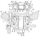
【図1】 本発明の実施の形態の1例を、等速ジョイントと組み合わせた状態で示す断面図。
【図2】 図1の上半部拡大断面図。
【図3】 図2のA矢示図。
【図4】 実施の形態の1例に使用する止め輪を、図1〜2の右方又は左方から見た状態で示す図。
【図5】 実施の形態の1例で、ナックルから車輪用軸受ユニットを取り外す為に使用する縮径治具を示す斜視図。
【図6】 縮径治具と止め輪との寸法関係が好ましくない状態を示す、図5のB矢視に相当する図。
【図7】 従来構造の1例を示す断面図。
【符号の説明】
1、1a 車輪用軸受ユニット
2、2a 等速ジョイント
3、3a 外輪
4、4a、4b ハブ
5、5a、5b 内輪
6 転動体
7 第一の取付フランジ
8 外輪軌道
9 第二の取付フランジ
10 第一の内輪軌道
11 小径段部
12 第二の内輪軌道
13 スプライン孔
14 等速ジョイント用外輪
15 等速ジョイント用内輪
16 ボール
17、17a スプライン軸
18、18a 駆動軸部材
19 外側係合溝
20 第二のスプライン孔
21 内側係合溝
22 保持器
23 雄ねじ部
24 ナット
25 駆動軸
26 雄スプライン部
27 係止溝
28 止め輪
29 係止段部
30 ナックル
31 嵌合部
32 支持孔
33 通孔
34 ボルト
35 ねじ孔
36、36a 回転部材
37 かしめ部
38 第二の止め輪
39 内側係止溝
40 外側係止溝
41 シールリング
42 筒部
43 キャップ
44 止め輪
45 内側係合溝
46 外側係合溝
47、47a 凹入部
48 ガイド面
49 縮径治具
50 円環部
51 係合突片
52 ガイド傾斜面
53 不連続部 [0001]
BACKGROUND OF THE INVENTION
The present invention relates to a wheel for rotatably supporting a wheel with respect to a suspension device by combining a wheel bearing unit for supporting the wheel and a support member constituting a part of an independent suspension of an automobile. The present invention relates to an improvement of a rotary support device for a vehicle.
[0002]
[Prior art]
In order to support a wheel rotatably with respect to a suspension device, various types of wheel bearing units are used in which an outer ring and an inner ring are rotatably combined via rolling elements. Further, in order to rotatably support a wheel with respect to an independent suspension, which is a kind of suspension device, the wheel bearing unit is provided in a support hole provided in a knuckle constituting a part of the independent suspension. A wheel rotation support device in which a part of an outer ring constituting the inner ring is fitted and the outer ring and the support member are coupled by a plurality of bolts has been widely used.FIG.Among such wheel rotation support devices, the drive wheel is supported by the independent suspension suspension, and the wheel drive wheel bearing unit 1 for rotating the drive wheel and the suspension device are configured. The general structure of the rotation support apparatus for wheels which combined the
[0003]
The wheel bearing unit 1 includes a
[0004]
Of these, the
[0005]
On the other hand, a constant velocity joint 2 is combined with the wheel bearing unit 1. The constant velocity joint 2 includes a constant velocity joint
[0006]
In order to combine the constant velocity joint 2 as described above and the wheel bearing unit 1 as described above, the spline shaft 17 is inserted into the
[0007]
Further, in the state of being assembled to the suspension device of the automobile, the
[0008]
In US Pat. No. 5,927,867, the outer peripheral surface of the outer ring constituting the wheel bearing unit is a simple cylindrical surface (not forming a mounting flange for fixing to the knuckle), and A structure in which an outer ring and a knuckle are coupled by an annular member is described. This annular member has a substantially L-shaped cross section and is formed in an annular shape as a whole. In addition, a protruding portion is formed on a part of the cylindrical portion constituting the annular member in a circumferential direction so as to protrude obliquely from the outer peripheral surface of the cylindrical portion. A groove is formed on the inner peripheral surface of one axial end of the support hole of the knuckle. And while inserting the said outer ring | wheel into this support hole, the axial direction other end surface of the said outer ring is contact | abutted to the side surface of the inward collar part provided in the axial direction other end part inner peripheral surface of this support hole. An annular member is externally fitted to the outer peripheral surface of one axial end portion of the outer ring, and the tip of the protruding portion is abutted against the side surface facing the other axial side of the both side surfaces of the groove portion. For this reason, the outer ring is prevented from being displaced in the direction of coming out from the inside of the support hole. In the case of the second example of the conventional structure described in US Pat. No. 5,927,867, it is not necessary to use a plurality of bolts for connecting the outer ring and the knuckle.
[0009]
Japanese Patent Application Laid-Open No. 2001-105806 describes a structure in which a knuckle and an outer ring constituting a wheel bearing unit are joined by an end clip having a shape made of an elastic material. In the case of the third example having such a conventional structure, an outer engagement groove formed in the circumferential direction of the inner circumferential surface of the knuckle support hole and an inner engagement groove formed in the circumferential direction of the outer circumferential surface of the outer ring are provided. Prepare. When the outer ring is coupled to the knuckle, the clip is mounted in the inner engagement groove, and the outer ring is inserted into the support hole in a state where the diameter of the clip is elastically reduced. When the clip is aligned with the outer engagement groove with the insertion operation, the diameter of the clip is elastically restored, so that the clip spans between the outer engagement groove and the inner engagement groove. Thus, the outer ring is prevented from being displaced in the direction of coming out of the support hole. In the case of the third example of the conventional structure described in Japanese Patent Laid-Open No. 2001-105806 as described above, it is not necessary to use a plurality of bolts in order to connect the outer ring and the knuckle.
[0010]
[Problems to be solved by the invention]
In either case, the second example of the conventional structure described in the aforementioned US Pat. No. 5,927,867 and the third example of the conventional structure described in the above-mentioned Japanese Patent Application Laid-Open No. 2001-105806 are both cases. In order to connect the outer ring and the knuckle, it is not necessary to use a plurality of bolts. However, in the case of each of these conventional structures, if there is a bearing abnormality such as peeling of the outer ring raceway or inner ring raceway during use, it will be necessary to inspect and repair the wheel bearing unit. The cost required increases. That is, for this inspection / repair, it is necessary to remove the wheel bearing unit from the support hole provided in the knuckle, but this removal work is easy in both cases of the second and third examples of the conventional structure described above. We do not consider to be able to go to. For this reason, when performing the above removal work with such a structure, it is necessary to pull out the outer ring from the support hole with a large force with a special tool such as a puller, but the annular member and the clip are not damaged. It is difficult to carry out the above removal work. Therefore, when the wheel bearing unit is inspected / repaired, it becomes necessary to replace the annular member or the clip, which increases the cost required for the inspection / repair. Further, when the outer ring is extracted from the support hole, the annular member or the outer engagement groove formed on the inner peripheral surface of the support hole of the knuckle or the inner engagement groove formed on the outer peripheral surface of the outer ring Since a large force is applied from the clip, there is a possibility that a part of the knuckle or the outer ring is damaged. In this case, it is necessary to replace the knuckle or the outer ring, and the cost required for the inspection / repair is further increased.
In view of such circumstances, the wheel rotation support device of the present invention has a structure in which an outer ring and a support member are coupled by a retaining ring, and is invented to reduce the cost required for inspection and repair of a wheel bearing unit. It is.
[0011]
[Means for Solving the Problems]
The wheel rotation support device of the present invention has the above-mentioned configuration.FIG.As in the first example of the conventional structure shown in FIG. 1, a suspension member is provided to support the wheel, and a wheel bearing unit supported on the inner diameter side of the support hole provided in the support member. .
Of these, the wheel bearing unit has an outer ring raceway on the inner peripheral surface, and an outer ring that does not rotate during use, and an outer peripheral surface that has a fitting portion on the outer peripheral surface for fitting into the support hole. A mounting flange for supporting the wheel at a portion near one end of the inner ring, and an inner ring raceway facing the outer ring raceway in the middle portion, respectively, and a rotating member that rotates during use, and the inner ring raceway and the outer ring raceway. And a plurality of rolling elements provided between the rolling elements.
[0012]
In particular, in the wheel rotation support device of the present invention, the outer peripheral surface of the fitting portion isIn the middle in the axial directionProvided in the circumferential directionInner engagement grooveAnd the inner peripheral surface of the support holeIn the middle in the axial directionProvided in the circumferential directionOuter engagement grooveAnd made of an elastic material, the whole is formed in a ring shape.Outer engagement grooveAnd aboveInner engagement grooveOf the retaining ring spanned between and the inner peripheral surface of the support hole.In a plurality of locations in the circumferential direction, each of which is recessed radially outward from the inner peripheral surface of the support hole, and each axial inner end reaches the axial inner end opening of the support hole, A plurality of recessed portions provided in the axial direction of the support hole in a state where the outer end in the axial direction reaches the outer side in the axial direction from the outer engagement groove.With. AndEach of theseEntered into the indentationjigThe tip ofEach of theseOf the retaining ring present in the recessed portion.Multiple locations in the circumferential directionBy engaging with the retaining ring, the outer diameter of the retaining ring can be elastically reduced below the inner diameter of the support hole.
[0013]
[Action]
According to the wheel rotation support device of the present invention configured as described above, it is provided on the inner peripheral surface of the support hole of the support member.Outer engagement grooveAnd provided in the fitting part of the outer ringInner engagement grooveSince a retaining ring is stretched between them, it is no longer necessary to use multiple bolts to connect the outer ring to the support member, reducing costs and reducing size and weight by facilitating assembly work. I can plan. In addition, since it is not necessary to provide a mounting flange for fixing to the support member on the outer peripheral surface of the outer ring, the shape of the outer peripheral surface of the outer ring can be simplified. And in the case of this invention, the operation | work which removes the wheel bearing unit from a support member can be performed easily. In addition, the retaining ring can be prevented from being damaged during the removal work, and the retaining ring can be reused. Further, since no large force is applied from the retaining ring to the knuckle and the outer ring during the detaching operation, the knuckle and the outer ring can be prevented from being damaged. Therefore, the cost required for inspection and repair of the wheel bearing unit can be reduced.
[0014]
DETAILED DESCRIPTION OF THE INVENTION
1 to 5 show the present invention.Example of embodimentIs shown. A feature of the present invention is a structure in which the
[0015]
The wheel rotation support device of the present invention includes a
[0016]
The wheel bearing unit 1a is combined with a constant velocity joint 2a. For this purpose, an inner locking groove 39 is formed on the outer peripheral surface of the
[0017]
In the case of this example, a seal ring is formed between the outer end surface of the constant velocity joint
[0018]
In particular, in the case of the wheel rotation support device of the present example, it spans between the inner peripheral surface of the
[0019]
Furthermore, in the case of this example, the recessed
[0020]
Then, with the
[0021]
The diameter d of the groove bottom of the
[0022]
In order to restrict the dimensions of the inner and
[0023]
The inner and
[0024]
On the other hand, when the wheel bearing unit 1a is removed from the
[0025]
In addition, the width W in the circumferential direction of each of the
[0026]
According to the wheel rotation support device of the present invention configured as described above, the
[0027]
Furthermore, in the case of this example, the coupling work of the
[0028]
One example of the embodiment described above isThe present invention has been described in the case where the present invention is applied to a structure for supporting a driving wheel of an automobile. However, the present invention is not limited to such a structure, for example, to support a driven wheel of an automobile. The present invention can also be implemented with this structure.
[0029]
【The invention's effect】
Since the present invention is configured and operates as described above, it is possible to reduce the cost and to reduce the size and weight by facilitating the assembling work, and to easily remove the wheel bearing unit from the support member. Moreover, it is possible to prevent the parts from being damaged during the removal operation. For this reason, parts can be reused, and the cost required for inspection and repair of the wheel bearing unit can be reduced.
[Brief description of the drawings]
FIG. 1 shows the implementation of the present invention.Example of formSectional drawing which shows this in the state combined with the constant velocity joint.
FIG. 2 is an enlarged cross-sectional view of the upper half of FIG.
FIG. 3 is an arrow A view of FIG.
[Fig. 4]Example of embodimentThe figure which shows the retaining ring used for 1 in the state seen from the right side or the left side of FIGS.
[Figure 5]Example of embodimentFIG. 6 is a perspective view showing a diameter-reducing jig used for removing the wheel bearing unit from the knuckle.
6 is a view corresponding to the view of arrow B in FIG. 5, showing a state in which the dimensional relationship between the diameter-reducing jig and the retaining ring is not preferable.
[Fig. 7]Sectional drawing which shows an example of a conventional structure.
[Explanation of symbols]
1, 1a Wheel bearing unit
2, 2a Constant velocity joint
3, 3a Outer ring
4, 4a, 4b hub
5, 5a, 5b Inner ring
6 Rolling elements
7 First mounting flange
8 Outer ring raceway
9 Second mounting flange
10 First inner ring raceway
11 Small diameter step
12 Second inner ring raceway
13 Spline hole
14 Outer ring for constant velocity joint
15 Inner ring for constant velocity joint
16 balls
17, 17a Spline shaft
18, 18a Drive shaft member
19 Outer engagement groove
20 Second spline hole
21 Inner engagement groove
22 Cage
23 Male thread
24 nuts
25 Drive shaft
26 Male spline section
27 Locking groove
28 Retaining Ring
29 Locking step
30 knuckle
31 Fitting part
32 Support hole
33 through holes
34 volts
35 Screw hole
36, 36a Rotating member
37 Caulking part
38 Second retaining ring
39 Inner locking groove
40 Outer locking groove
41 Seal ring
42 Tube
43 cap
44 Retaining Ring
45 Inner engagement groove
46 Outer engagement groove
47, 47a Recessed part
48 Guide surface
49 Diameter reduction jig
50 torus
51 engagement protrusion
52 Guide inclined surface
53Discontinuity
Claims (2)
Priority Applications (1)
| Application Number | Priority Date | Filing Date | Title |
|---|---|---|---|
| JP2001323856A JP3960005B2 (en) | 2001-10-22 | 2001-10-22 | Rotation support device for wheels |
Applications Claiming Priority (1)
| Application Number | Priority Date | Filing Date | Title |
|---|---|---|---|
| JP2001323856A JP3960005B2 (en) | 2001-10-22 | 2001-10-22 | Rotation support device for wheels |
Publications (3)
| Publication Number | Publication Date |
|---|---|
| JP2003127608A JP2003127608A (en) | 2003-05-08 |
| JP2003127608A5 JP2003127608A5 (en) | 2005-06-09 |
| JP3960005B2 true JP3960005B2 (en) | 2007-08-15 |
Family
ID=19140681
Family Applications (1)
| Application Number | Title | Priority Date | Filing Date |
|---|---|---|---|
| JP2001323856A Expired - Fee Related JP3960005B2 (en) | 2001-10-22 | 2001-10-22 | Rotation support device for wheels |
Country Status (1)
| Country | Link |
|---|---|
| JP (1) | JP3960005B2 (en) |
Families Citing this family (6)
| Publication number | Priority date | Publication date | Assignee | Title |
|---|---|---|---|---|
| JP4877904B2 (en) * | 2005-07-27 | 2012-02-15 | Ntn株式会社 | Drive wheel bearing device and axle module including the same |
| JP4637723B2 (en) * | 2005-11-08 | 2011-02-23 | Ntn株式会社 | Sliding constant velocity universal joint |
| JP5101051B2 (en) * | 2006-06-22 | 2012-12-19 | Ntn株式会社 | Drive wheel bearing unit |
| JP2010091055A (en) * | 2008-10-09 | 2010-04-22 | Ntn Corp | Chain tensioner |
| JP6041388B2 (en) * | 2013-04-16 | 2016-12-07 | 日本オイルポンプ株式会社 | Hydraulic motor |
| JP2020193668A (en) * | 2019-05-28 | 2020-12-03 | 本田技研工業株式会社 | Removal method of bearing |
-
2001
- 2001-10-22 JP JP2001323856A patent/JP3960005B2/en not_active Expired - Fee Related
Also Published As
| Publication number | Publication date |
|---|---|
| JP2003127608A (en) | 2003-05-08 |
Similar Documents
| Publication | Publication Date | Title |
|---|---|---|
| EP2127902B1 (en) | Bearing device for driving wheel, and its assembling method | |
| JP3960005B2 (en) | Rotation support device for wheels | |
| JP3533883B2 (en) | Hub unit for wheel support | |
| JP4696466B2 (en) | Method and apparatus for manufacturing rolling bearing unit for drive wheel | |
| JP2003130072A (en) | Rotation support device for wheels | |
| JP2009150418A (en) | Wheel bearing device | |
| JP2002219903A (en) | Bearing unit for wheel drive | |
| JP2003159908A (en) | Drive wheel rotation support device | |
| JP4779953B2 (en) | Bearing unit manufacturing method and bearing unit | |
| JP2001246906A (en) | Bearing unit for wheel drive | |
| JP3893933B2 (en) | Rotating support device for wheel and assembling method thereof | |
| JP2003148501A (en) | Rotation support device for wheel and its assembling method | |
| JP2003130073A (en) | Rotation support device for wheels | |
| JP4042528B2 (en) | Rolling bearing device | |
| JP2012011811A (en) | Driving unit for wheel | |
| JP2000229501A (en) | Hub unit for wheel support | |
| JP4738760B2 (en) | Constant velocity joint and wheel hub assembly | |
| JP2002301532A (en) | Method for caulking bearing device | |
| JP4269422B2 (en) | Rolling bearing unit for wheels | |
| JP4453033B2 (en) | Manufacturing method of wheel supporting hub unit | |
| JP2003039909A (en) | Bearing unit for wheel drive | |
| JP2001206004A (en) | Bearing unit for wheel drive | |
| JP2010047043A (en) | Bearing device for driving wheel, and axle unit equipped with the bearing device | |
| JP2003028150A (en) | Bearing device | |
| JP2002337504A (en) | Method of assembling wheel drive bearing unit and jig for assembling |
Legal Events
| Date | Code | Title | Description |
|---|---|---|---|
| A521 | Written amendment |
Free format text: JAPANESE INTERMEDIATE CODE: A523 Effective date: 20040906 |
|
| A621 | Written request for application examination |
Free format text: JAPANESE INTERMEDIATE CODE: A621 Effective date: 20040906 |
|
| A131 | Notification of reasons for refusal |
Free format text: JAPANESE INTERMEDIATE CODE: A131 Effective date: 20061114 |
|
| A977 | Report on retrieval |
Free format text: JAPANESE INTERMEDIATE CODE: A971007 Effective date: 20061120 |
|
| A521 | Written amendment |
Free format text: JAPANESE INTERMEDIATE CODE: A523 Effective date: 20070111 |
|
| TRDD | Decision of grant or rejection written | ||
| A01 | Written decision to grant a patent or to grant a registration (utility model) |
Free format text: JAPANESE INTERMEDIATE CODE: A01 Effective date: 20070424 |
|
| A61 | First payment of annual fees (during grant procedure) |
Free format text: JAPANESE INTERMEDIATE CODE: A61 Effective date: 20070507 |
|
| R150 | Certificate of patent or registration of utility model |
Free format text: JAPANESE INTERMEDIATE CODE: R150 Ref document number: 3960005 Country of ref document: JP Free format text: JAPANESE INTERMEDIATE CODE: R150 |
|
| FPAY | Renewal fee payment (event date is renewal date of database) |
Free format text: PAYMENT UNTIL: 20100525 Year of fee payment: 3 |
|
| FPAY | Renewal fee payment (event date is renewal date of database) |
Free format text: PAYMENT UNTIL: 20110525 Year of fee payment: 4 |
|
| FPAY | Renewal fee payment (event date is renewal date of database) |
Free format text: PAYMENT UNTIL: 20120525 Year of fee payment: 5 |
|
| FPAY | Renewal fee payment (event date is renewal date of database) |
Free format text: PAYMENT UNTIL: 20130525 Year of fee payment: 6 |
|
| FPAY | Renewal fee payment (event date is renewal date of database) |
Free format text: PAYMENT UNTIL: 20130525 Year of fee payment: 6 |
|
| FPAY | Renewal fee payment (event date is renewal date of database) |
Free format text: PAYMENT UNTIL: 20140525 Year of fee payment: 7 |
|
| LAPS | Cancellation because of no payment of annual fees |