JP3946634B2 - Geothermal use structure - Google Patents
Geothermal use structure Download PDFInfo
- Publication number
- JP3946634B2 JP3946634B2 JP2002530458A JP2002530458A JP3946634B2 JP 3946634 B2 JP3946634 B2 JP 3946634B2 JP 2002530458 A JP2002530458 A JP 2002530458A JP 2002530458 A JP2002530458 A JP 2002530458A JP 3946634 B2 JP3946634 B2 JP 3946634B2
- Authority
- JP
- Japan
- Prior art keywords
- building
- underground
- heat insulating
- heat
- insulating wall
- Prior art date
- Legal status (The legal status is an assumption and is not a legal conclusion. Google has not performed a legal analysis and makes no representation as to the accuracy of the status listed.)
- Expired - Fee Related
Links
Images


Classifications
-
- F—MECHANICAL ENGINEERING; LIGHTING; HEATING; WEAPONS; BLASTING
- F24—HEATING; RANGES; VENTILATING
- F24T—GEOTHERMAL COLLECTORS; GEOTHERMAL SYSTEMS
- F24T10/00—Geothermal collectors
-
- E—FIXED CONSTRUCTIONS
- E02—HYDRAULIC ENGINEERING; FOUNDATIONS; SOIL SHIFTING
- E02D—FOUNDATIONS; EXCAVATIONS; EMBANKMENTS; UNDERGROUND OR UNDERWATER STRUCTURES
- E02D31/00—Protective arrangements for foundations or foundation structures; Ground foundation measures for protecting the soil or the subsoil water, e.g. preventing or counteracting oil pollution
-
- E—FIXED CONSTRUCTIONS
- E02—HYDRAULIC ENGINEERING; FOUNDATIONS; SOIL SHIFTING
- E02D—FOUNDATIONS; EXCAVATIONS; EMBANKMENTS; UNDERGROUND OR UNDERWATER STRUCTURES
- E02D29/00—Independent underground or underwater structures; Retaining walls
-
- E—FIXED CONSTRUCTIONS
- E04—BUILDING
- E04B—GENERAL BUILDING CONSTRUCTIONS; WALLS, e.g. PARTITIONS; ROOFS; FLOORS; CEILINGS; INSULATION OR OTHER PROTECTION OF BUILDINGS
- E04B1/00—Constructions in general; Structures which are not restricted either to walls, e.g. partitions, or floors or ceilings or roofs
- E04B1/62—Insulation or other protection; Elements or use of specified material therefor
- E04B1/74—Heat, sound or noise insulation, absorption, or reflection; Other building methods affording favourable thermal or acoustical conditions, e.g. accumulating of heat within walls
- E04B1/76—Heat, sound or noise insulation, absorption, or reflection; Other building methods affording favourable thermal or acoustical conditions, e.g. accumulating of heat within walls specifically with respect to heat only
-
- Y—GENERAL TAGGING OF NEW TECHNOLOGICAL DEVELOPMENTS; GENERAL TAGGING OF CROSS-SECTIONAL TECHNOLOGIES SPANNING OVER SEVERAL SECTIONS OF THE IPC; TECHNICAL SUBJECTS COVERED BY FORMER USPC CROSS-REFERENCE ART COLLECTIONS [XRACs] AND DIGESTS
- Y02—TECHNOLOGIES OR APPLICATIONS FOR MITIGATION OR ADAPTATION AGAINST CLIMATE CHANGE
- Y02A—TECHNOLOGIES FOR ADAPTATION TO CLIMATE CHANGE
- Y02A30/00—Adapting or protecting infrastructure or their operation
- Y02A30/24—Structural elements or technologies for improving thermal insulation
- Y02A30/244—Structural elements or technologies for improving thermal insulation using natural or recycled building materials, e.g. straw, wool, clay or used tires
-
- Y—GENERAL TAGGING OF NEW TECHNOLOGICAL DEVELOPMENTS; GENERAL TAGGING OF CROSS-SECTIONAL TECHNOLOGIES SPANNING OVER SEVERAL SECTIONS OF THE IPC; TECHNICAL SUBJECTS COVERED BY FORMER USPC CROSS-REFERENCE ART COLLECTIONS [XRACs] AND DIGESTS
- Y02—TECHNOLOGIES OR APPLICATIONS FOR MITIGATION OR ADAPTATION AGAINST CLIMATE CHANGE
- Y02A—TECHNOLOGIES FOR ADAPTATION TO CLIMATE CHANGE
- Y02A30/00—Adapting or protecting infrastructure or their operation
- Y02A30/27—Relating to heating, ventilation or air conditioning [HVAC] technologies
- Y02A30/272—Solar heating or cooling
-
- Y—GENERAL TAGGING OF NEW TECHNOLOGICAL DEVELOPMENTS; GENERAL TAGGING OF CROSS-SECTIONAL TECHNOLOGIES SPANNING OVER SEVERAL SECTIONS OF THE IPC; TECHNICAL SUBJECTS COVERED BY FORMER USPC CROSS-REFERENCE ART COLLECTIONS [XRACs] AND DIGESTS
- Y02—TECHNOLOGIES OR APPLICATIONS FOR MITIGATION OR ADAPTATION AGAINST CLIMATE CHANGE
- Y02B—CLIMATE CHANGE MITIGATION TECHNOLOGIES RELATED TO BUILDINGS, e.g. HOUSING, HOUSE APPLIANCES OR RELATED END-USER APPLICATIONS
- Y02B10/00—Integration of renewable energy sources in buildings
- Y02B10/20—Solar thermal
-
- Y—GENERAL TAGGING OF NEW TECHNOLOGICAL DEVELOPMENTS; GENERAL TAGGING OF CROSS-SECTIONAL TECHNOLOGIES SPANNING OVER SEVERAL SECTIONS OF THE IPC; TECHNICAL SUBJECTS COVERED BY FORMER USPC CROSS-REFERENCE ART COLLECTIONS [XRACs] AND DIGESTS
- Y02—TECHNOLOGIES OR APPLICATIONS FOR MITIGATION OR ADAPTATION AGAINST CLIMATE CHANGE
- Y02B—CLIMATE CHANGE MITIGATION TECHNOLOGIES RELATED TO BUILDINGS, e.g. HOUSING, HOUSE APPLIANCES OR RELATED END-USER APPLICATIONS
- Y02B10/00—Integration of renewable energy sources in buildings
- Y02B10/40—Geothermal heat-pumps
-
- Y—GENERAL TAGGING OF NEW TECHNOLOGICAL DEVELOPMENTS; GENERAL TAGGING OF CROSS-SECTIONAL TECHNOLOGIES SPANNING OVER SEVERAL SECTIONS OF THE IPC; TECHNICAL SUBJECTS COVERED BY FORMER USPC CROSS-REFERENCE ART COLLECTIONS [XRACs] AND DIGESTS
- Y02—TECHNOLOGIES OR APPLICATIONS FOR MITIGATION OR ADAPTATION AGAINST CLIMATE CHANGE
- Y02E—REDUCTION OF GREENHOUSE GAS [GHG] EMISSIONS, RELATED TO ENERGY GENERATION, TRANSMISSION OR DISTRIBUTION
- Y02E10/00—Energy generation through renewable energy sources
- Y02E10/10—Geothermal energy
Landscapes
- Engineering & Computer Science (AREA)
- Life Sciences & Earth Sciences (AREA)
- General Engineering & Computer Science (AREA)
- Structural Engineering (AREA)
- Civil Engineering (AREA)
- Paleontology (AREA)
- Mechanical Engineering (AREA)
- Combustion & Propulsion (AREA)
- Environmental & Geological Engineering (AREA)
- Architecture (AREA)
- General Life Sciences & Earth Sciences (AREA)
- Mining & Mineral Resources (AREA)
- Chemical & Material Sciences (AREA)
- Sustainable Energy (AREA)
- Sustainable Development (AREA)
- Physics & Mathematics (AREA)
- Acoustics & Sound (AREA)
- Hydrology & Water Resources (AREA)
- Electromagnetism (AREA)
- Building Environments (AREA)
- Engine Equipment That Uses Special Cycles (AREA)
- Greenhouses (AREA)
- Photovoltaic Devices (AREA)
- Cultivation Of Seaweed (AREA)
- Artificial Fish Reefs (AREA)
- Preparation Of Compounds By Using Micro-Organisms (AREA)
Abstract
Description
技術分野
本発明は、地熱を建築物の冷暖房等に利用する地熱利用構造物に関する。
背景技術
従来の地熱利用には、例えば空気又は水を熱媒体とした熱交換用のダクト又はパイプを、地下室、地中埋設パイプ等から建築物内へと延ばし、地中内で加温又は冷却した熱媒体を建築物内に循環させて冷暖房の用に供したり、熱交換により作動する装置により動力を取出す態様のものが多かった。また、低温の地中恒温層(年間を通じて温度変化の少ない地中部分)を利用して、この地中恒温層に達する洞窟に食料等を保存したり、保存物を穴に収納し、覆土埋設する等して、地熱を利用していた。
地中の温度変化は、主として太陽熱の照射により地表面から一定深さの範囲で生じている。前記一定深さより深い地中では、季節によって温度変化がほとんどない地中恒温層になっており、深くなるほどに熱エネルギーは上昇する。地表面から一定深さ、すなわち地中恒温層表層は、相対的に、夏季においては地表面より低温で、冬季においては地表面より高温である。こうした地中恒温層の熱エネルギーを建築物内へ導くと、夏季には冷房、冬季には暖房の用に供することができる。そして、前記地中恒温層の熱エネルギーは事実上無尽蔵な自然エネルギーであり、他の自然エネルギー(太陽熱又は光、風力、水力等)に比べて安定かつ利用しやすい利点(建築物直下に存在するため、熱エネルギーを導きやすい)がある。上記地熱利用の例は、こうした地熱の利点に着目したものであるが、まだ十分に利用されているとは言い難い。そこで、限りある石油、ガス、石炭等、化石エネルギーの枯渇を防止するため、ヒータ、エアコンディショナー等や、太陽熱又は光、風力、水力等の自然エネルギーを補助的に用いながら、地中恒温層の熱エネルギーをより有効に利用する手段について検討した。
発明の開示
検討の結果開発したものが、地表面から地中恒温層まで延びる断熱壁が建築物を囲んで埋設してなる地熱利用構造物である。具体的には、断熱壁は、建築物の基礎を囲んで埋設する。この場合、(a)断熱壁は、基礎の地上露出部位及び地下埋設部位に密着して埋設してもよいし、(b)基礎の地上露出部位又は地下埋設部位から離隔して埋設してもよい。更に、断熱壁を基礎の地上露出部位から離隔して埋設した場合、地表面から突出する断熱壁上部と基礎との間に空間ができるので、この空間と建築物内とを連通する内側換気部を前記地上露出部位又は建築物の壁面に設け、この空間と外部とを連通する外側換気部を断熱壁に設けるとよい。例えば、内外側換気部それぞれに換気ファンを設けたり、内外側換気部を連通する熱交換ダクトを配してもよい。
本発明は、地中の深度方向における温度分布に従って、温度変動が安定する地中恒温層まで埋設した断熱壁で建築物の四方を囲むことにより、建築物内と建築物下の地面との熱交換範囲を建築物直下の領域に限定し、建築物内の温度変化をもたらす無駄な熱交換を抑制する。夏季における断熱壁は、建築物周囲の地面、とりわけ建築物周囲の地表面に照射する太陽熱による熱エネルギーが地中を介して基礎から建築物内に取込まれる熱交換を遮断し、建築物直下の地面を建築物に対して相対的低温に保つことで、建築物内の冷房効果を高める。また、冬季における断熱壁は、基礎を通じて建築物周囲の地中に逃げようとする暖房の熱エネルギーの離散を防止し、建築物内の暖房効果を高める。
表1は日本各地の1月(冬季)及び7月(夏季)における地表面(深さ0.0m)〜地中恒温層(3.0m)の範囲での温度分布をまとめたものであり、広島における冬季の地中温度分布を図53に、そして同じく広島における夏季の地中温度分布を図54に示す。例えば広島(表1中太枠線内)の冬季1月平均温度は、表1及び図53に見られるように、地表面39で5.0℃、深さ1m層40で7.4℃、深さ2m層41で13.9℃、そして深さ3m層(=地中恒温層)42で16.0℃で、地中恒温層42は地表面39に比べて11.0℃の高温である。しかし、外気との熱交換が盛んな床下47は2.3℃と地表面より低温になっている。また、広島の夏季7月平均温度は、表1及び図54に見られるように、地表面43では29.6℃、深さ1m層44で25.4℃、深さ2m層45で19.5℃、そして深さ3m層(=地中恒温層)46で17.3℃で、地中恒温層46は地表面43に比べて12.3℃の低温である。この夏季においても、熱交換が盛んな床下49は24.3℃であり、地表面43からの熱輻射等により日陰であるにも拘わらず、かなり温度が高くなっている。

こうした本発明の適用可能な建築物は、(1)建築物底面が断熱壁に囲まれた地表面に直接接触していてもよいし、(2)建築物底面と断熱壁に囲まれた地表面との間に砕石を充填していてもよいし、(3)建築物底面の部分又は全部に及ぶベタ基礎が断熱壁に囲まれた地表面に直接接触していてもよいし、更に(4)建築物底面の部分又は全部に及ぶベタ基礎と断熱壁に囲まれた地表面との間に砕石を充填していてもよい。このように、本発明による建築物内と建築物周囲の地面との熱交換の遮断は建築物周囲の断熱壁によって実現するため、建築物の基礎部分がどのようであっても本発明は利用可能である。
本発明を特徴付ける断熱壁は、(A)合成樹脂製断熱パネルである場合を基本とする。具体的には、断熱壁は複数の合成樹脂製断熱パネルを連接してなり、各合成樹脂製断熱パネルは相互に連接する突き合せ縁の一方に嵌合条、残る他方に嵌合溝を有する構造とする。この合成樹脂製断熱パネルには、断熱壁の内外を連通する通湿孔を設けてもよい。一般に、断熱パネルは通気性又は通水性が劣り、建築物周囲を断熱パネルで囲むと建築物直下の水はけが悪くなる虞れがあるため、通湿孔を設けるとよい。このほか、断熱壁は、(B)合成樹脂又は金属製中空パイプを相互に密着状態で連設して構成してもよい。この合成樹脂又は金属製中空パイプにも、断熱壁の内外を連通する通湿孔を設けることができる。複数本のパイプを建築物内外方向に並べて断熱壁を構成する場合、各パイプの通湿孔は直線状に連通する必要はなく、各パイプの通湿孔が互い違いになっても、断熱壁全体として通気性又は通水性を発揮できればよい。
発明を実施するための最良の形態
以下、図面に示す実施の形態により本発明を詳細に説明する。
図1は本発明に用いる断熱パネルを示した斜視図、図2は別例の断熱パネルを示した斜視図、図3は断熱パネルを埋設して断熱壁を構築した状態を示す断面図、図4は断熱パネルを埋設して断熱壁を構築した状態を示す平面図、図5は別例の断熱パネルを示した斜視図、図6は別例の断熱パネルを示した斜視図、図7は別例の断熱パネルを埋設して断熱壁を構築した状態を示す断面図、図8は別例の断熱パネルを埋設して断熱壁を構築した状態を示す平面図、図9は別例の断熱パネルを示した斜視図で、図10は別例の断熱パネルを示した斜視図、図11は別例の断熱パネルを埋設して断熱壁を構築した状態を示す断面図、図12は別例の断熱パネルを埋設して断熱壁を構築した状態を示す平面図、図13は建築物の基礎に密接して断熱壁を構築した状態を示す断面図、図14は建築物の基礎から離隔して断熱壁を構築した状態を示す断面図、図15は別例の建築物の基礎に密接して断熱壁を構築した状態を示す断面図、図16は別例の建築物の基礎から離隔して断熱壁を構築した状態を示す断面図、図17は別例の建築物の基礎に密接して断熱壁を構築した状態を示す断面図、図18は別例の建築物の基礎から離隔して断熱壁を構築した状態を示す断面図、図19は建築物の基礎に密接して断熱壁を構築した状態を示す断面図、図20は建築物の基礎に密接して断熱壁を構築した状態を示す断面図、図21は地中梁を有する基礎に密接して断熱壁を構築した状態を示す断面図、図22は地中梁を有する基礎から離隔して断熱壁を構築した状態を示す断面図、図23は地中梁を有する基礎から離隔して断熱壁を構築した状態を示す断面図、図24は地中梁を有する基礎から離隔して断熱壁を構築した状態を示す断面図、図25は地熱利用地上構造物に密接して断熱壁を構築した状態を示す断面図、図26は地熱利用地上構造物から離隔して断熱壁を構築した状態を示す断面図、図27は地熱利用地下構造物に密接して断熱壁を構築した状態を示す断面図、図28は地熱利用地下構造物から離隔して断熱壁を構築した状態を示す断面図、図29はビニールハウスに密接して断熱壁を構築した状態を示す断面図、図30はビニールハウスから離隔して断熱壁を構築した状態を示す断面図、図31は断熱壁と地中温度分布との関係を表した断面図、図32は断熱壁と地中温度分布との関係を表した別例の断面図、図33は断熱壁と地中温度分布との関係を表した別例の断面図、図34は断熱壁と地中温度分布との関係を表した別例の断面図、図35は断熱壁と地中温度分布との関係を表した別例の断面図、図36は断熱壁と地中温度分布との関係を表した別例の断面図、図37は断熱壁と地中温度分布との関係を表した別例の断面図、図38は断熱壁と地中温度分布との関係を表した別例の断面図、図39は建築物と断熱壁との空間を介して外気を導入する状態を示す断面図、図40は建築物と断熱壁との空間を介して外気を導入する状態を示す平面図、図41は建築物と断熱壁との空間を介して補助冷暖房設備を利用する状態を示す断面図、図42は建築物と断熱壁との空間を介して補助冷暖房設備を利用する状態を示す平面図、図43はより実際的な本発明の適用例を示す断面図、図44はより実際的な本発明の別の適用例を示す断面図、図45は耐震構造の建築物の断面図、図46は本発明を適用した耐震構造の建築物の断面図、図47は別例の耐震構造建築物の断面図、図48は本発明を適用した別例の耐震構造の建築物の断面図、図49は建築物外壁に沿って断熱壁を延長した例を示す断面図、図50は建築物外壁に沿って断熱壁を延長した別例を示す断面図、図51は中空パイプからなる断熱壁を示す断面図、図52は中空パイプからなる断熱壁を示す平面図、図53は広島における冬期地中温度分布帯を示す断面図であり、そして図54は広島における夏期地中温度分布帯を示す断面図である。
また、各図中、符号1は断熱パネル、符号2は通湿孔、符号3は地中、符号4は地表面、符号5は基礎、符号6は土台、符号7は柱、符号8は内壁、符号9は外壁、符号10は水切、符号11は空間、符号12は床下、符号13は鉄骨、符号14は土間、符号15はビニールハウス、符号16は畝、符号17は床、符号18は室内、符号19は深さ1m層、符号20は深さ2m層、符号21は深さ3m層(地中恒温層)、符号22は建築物、符号23は屋根、符号24は天井、符号25はハウス内、符号26は外気、符号27は建築物壁、符号28は空気浄化装置、符号29は換気装置、符号30はダクト、符号31は熱媒体、符号32は基礎コンクリート、符号33は割栗石、符号34は防湿シート、符号35は上部断熱パネル、符号36は中空パイプ、符号37は建築物上部、符号38は地下室、符号39は地表面(5.0℃)、符号40は深さ1m層(7.4℃)、符号41は深さ2m層(13.9℃)、符号42は深さ3m層(16.0℃、地中恒温槽)、符号43は地表面(29.6℃)、符号44は深さ1m層(25.4℃)、符号45は深さ2m層(19.5℃)、符号46は深さ3m層(17.3℃、地中恒温槽)、符号47は床下(2.3℃)、符号49は床下(24.3℃)、符号50は嵌合条、符号51は嵌合溝、符号52は地中梁であり、符号Aは断熱壁を表す。
本発明では、図1及び図2に見られる合成樹脂断熱パネル1を用いて、図3及び図4に見られる断熱壁Aを構築する。図1及び図2に例示する断熱パネル1は、地表面4から地中3に向けて深く埋設できる高さを有する合成樹脂製断熱パネルであって、左側縁(図1中奥)及び上縁に嵌合条50、右側縁(図1中手前)に嵌合溝51を有し、横並びの断熱パネル1,1相互を嵌合状態で連接する。また、断熱パネル面には内外に連通する通湿孔2を設けている。図2の例は、図1の断熱パネル1に対して下右角部を切り欠いている。
断熱パネル1相互は連接できればよく、嵌合条及び嵌合溝は必須の構成ではない。よって、図1又は図2の断熱パネル1に代えて、上縁の嵌合条を省いた図5又は図6の断熱パネル1を用いて、図7及び図8に見られる断熱壁Aを構築してもよい。また、湿度の低い地域であれば、地中3における通気性又は通水性を気にしなくてもよいので、図5又は図6の断熱パネルから更に通湿孔を省いた図9又は図10の断熱パネル1を用いて、図11及び図12に見られる断熱壁Aを構築してもよい。
次に、本発明の具体的な適用例について説明する。
本発明の建築物22への適用は、図13に見られるように、基本的には基礎(本例は逆T字断面の標準的な布基礎)5に密接して断熱パネル1を埋設し、好ましくは外壁9に及ぶように断熱パネル1を延設して断熱壁Aを構築するとよい。すなわち、地表面4を境として上下に断熱壁Aを延ばす。この場合、断熱壁Aの埋設部分には通湿孔2を設けた断熱パネル1を用いながら、同断熱壁Aの地上部分の断熱パネル1には通湿孔2が必要なく、断熱壁Aの最上端は水切10で覆っておくとよい。こうして、地中3(正確には地中恒温層)から地上に至る範囲で断熱壁Aに囲まれた範囲の基礎5に対して土台6を設け、この土台6上に柱7、内壁8及び外壁9からなる建築物22を建てれば、建築物22、特に床下12は地中の熱交換から隔離された空間とすることができる。
断熱パネル1を基礎5から空間11を設けて離隔すると、図14に見られるように地中3から地表面4に至る連続した1枚の断熱パネル1で断熱壁Aを構築できる。この場合、空間11は断熱壁Aと建築物22との間における空気断熱層を構成して、本発明の作用、効果を高める働きを有する。また、直線状断面の布基礎5であれば、図15に見られるように、基礎5に密接して地中3から地表面4に至る連続した1枚の断熱パネル1で断熱壁Aを構築できる。この場合でも、図16に見られるように、基礎5から空間11を設けて断熱パネル1を離隔して断熱壁Aを構築してもよい。更に、湿気の少ない場所では、図17及び図18に見られるように、通湿孔を省略した断熱パネル1で断熱壁Aを構築してもよい。
本発明は、断熱壁を地中恒温層、およそ深さ3m層にまで埋設することを主眼としているが、実際上、地盤の硬さによっては前記深さを望めない場合も少なくない。こうした場合、図19及び図20に見られるように、基礎5までは地中3を掘削するのであるから、あくまで基礎5に断熱パネル1を密接させて、少しでも断熱壁Aが深いところに及ぶようにするとよい。
本発明は上記布基礎5に限らず、他の基礎についても適用できる。
本発明は、図21及び図22に見られるように、地中梁52を有する基礎5に対しても上述同様適用できる。この場合、地中梁52下、基礎5内を土壌で満たすことができ、建築物22としての安定性が増すほか、建築物22と地中3との熱的一体性を確保できる。この場合も、図23及び図24に見られるように、基礎5から断熱壁Aを離隔して構築することもできる。
基礎のない簡易な建築物22に対しても、本発明は適用可能である。例えば、図25に見られるように、土間14上に柱7,7を立設して、基礎のない建築物上部37のみを有する簡易な建築物22では、外壁9に密接して断熱パネル1を埋設し、断熱壁Aを構築する。この場合も、図26に見られるように、外壁9から空間11を設けて離隔した断熱壁Aとしてもよい。また、地下室38を構成するベタ基礎5を有する建築物22に対しては、図27及び図28に見られるように、本発明の断熱壁Aを構築できる。このほか、図29及び図30に見られるように、畝16をハウス25内に有するビニールハウス15にも、上述同様本発明を適用できる。
次に、本発明の具体的な働きを説明する。図31〜図34は一般家屋の建築物22を、図35〜図38はビニールハウス15を用いた例である。
図31に見られる例は、地中梁52を有する基礎5上に土台6を築き、この土台6上に床17、建物壁27、天井24に囲まれた室内18を構成し、及び屋根23からなる建築物22を建築した例である。断熱壁Aは、地表面4から深さ1m層19、深さ2m層20を突き抜けて深さ3m層(地中恒温層)21に達する断熱パネル1を、基礎5に密接した状態で地中3に埋設して構成している。断熱壁A上端は水切10で塞いでいる点は上述の各例と同様である。
断熱壁Aは、地中3における建築物22周囲と断熱壁Aに囲まれた建築物22直下の深さ1m層19、深さ2m層20及び深さ3m層(地中恒温層)21の熱交換を遮断している。これにより、室内18は深さ1m層19及び深さ2m層20を介して深さ3m層(地中恒温層)21との間での熱交換をするようになる。すなわち、夏季では、外気に対して相対的に低温な深さ3m層(地中恒温層)21との熱交換により室内18は冷却され、逆に冬季では、外気に対して相対的に高温な深さ3m層(地中恒温層)21との熱交換により室内18は暖房され、それぞれ室内18の冷房又は暖房に要する外部エネルギー(電気やガス)を低減できることになる。この場合、室内18と地中1m層とを隔てる部分での熱交換損失を抑えるように、本例(図31)に見られるように、床17、土台6及び地中梁52を密接させるとよい。また、基礎5の地上露出部位における外気との熱交換の影響を抑制するには、図32に見られるように、基礎5から空間11を開けて断熱パネル1を埋設するとよい。
このように、断熱壁Aは建築物周囲の地中と建築物直下の地中との熱交換を遮断することにより、室内に対して相対的低温(夏季)又は相対的高温(冬季)となる地中恒温層と室内との熱交換による冷房又は暖房を図るものである。よって、基本的には断熱壁Aの埋設深さが深いほど好ましいわけであるが、前記作用が実現されるのであれば、断熱壁Aの埋設深さは浅くてもよく、例えば図33又は図34に見られるように、深さ2m層20に達する程度の断熱壁Aであってもよい。
また、上記断熱壁Aの作用は、あくまで建築物周囲に断熱パネルを埋設することにより実現するものであるから、図35、図36、図37及び図38に見られるように、建築物がビニールハウス15に変ったとしても、断熱壁Aの作用はハウス内25に及ぶ。この結果、ハウス内25の温度維持に必要な外部エネルギーが低減されるから、従来に比べて低コストでのビニールハウス15の利用が可能となる効果が得られる。
上述までの例示で、建築物又は基礎と断熱壁との間に空間を設けた場合、断熱壁の作用は前記空間にも及ぶ。このため、例えば室内18の換気を図る場合、図39及び図40に見られるように、外気26を直接取込むのではなく、空間11を通して冷却(夏季)又は暖房(冬季)した外気26を取込むとよい。図39の例では、断熱壁A及び建築物壁27それぞれの対称位置に空気浄化装置28及び換気装置29を配し、空間11を迂回して外気26を室内18へ取込むようにしている。
また、空間11を通過させることで、一定程度の冷却(夏季)又は暖房(冬季)が見込めることを利用して、図41及び図42に見られるように、補助冷暖房設備の熱媒体(空気、水又はその他の冷暖房媒体)を通すダクト30を空間11を通して断熱壁A外から室内18へと延設してもよい。この結果、例えば夏季においては、ダクト30を通す冷房媒体の昇温が抑制され、損失の少ない補助冷房設備の利用が可能になる。冬季においても、暖房媒体の降温が抑制され、損失の少ない補助暖房設備の利用が可能になる。
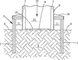
より実際的な建築物22に本発明を適用した場合、図43及び図44に見られるように、まず割栗石33を敷き、基礎コンクリート32を打設して基礎5を構成するため、断熱壁Aは割栗石33を超えた深さにまで達することが望ましい。また、例えば図45に見られるような基礎コンクリート32及び基礎5を囲み、地中梁52までの範囲を満たす割栗石33の充填層を構成した耐震構造の建築物22に本発明を適用する場合は、図46に見られるように、前記割栗石33の充填層を囲み、この充填層より深い地中3に達する断熱壁Aを構築するとよい。本例(図47)のように、基礎コンクリート32及び基礎5との間及び地中梁52下面に沿って防湿シート34を配した耐震構造の建築物22に対しても、図48に見られるように本発明を適用することができる。
本発明の断熱壁による作用、効果をよりよく発揮するには、建築物自体が外気と直接熱交換せず、地中恒温層との間でだけ熱交換する状態にするとよい。例えば、図49又は図50に見られるように、断熱壁Aに上部断熱パネル35を継ぎ足して断熱壁A全体として上方に延設した構成とし、建築物22側面全体を断熱壁Aで覆うようにするとよい。これにより、室内18は下方、地中3に向けてのみ熱交換できるようになり、本発明を適用した場合の作用、効果がよりよく発揮できる。
本発明の断熱壁Aは、最も簡易には断熱パネルを用いて構築するが、熱交換を遮断する作用の観点から、断熱性が発揮されるような構成であれば、多種多様な断熱壁Aを利用できる。中でも、図51及び図52に見られるように、多数の中空パイプ36を基礎5に密接して埋設し、断熱壁Aを構成する場合が好ましい。中空パイプA中の空気層が断熱層を形成するため、中空パイプ36相互が密接することの伝熱による熱交換を差し引いても、本発明の断熱壁Aとして用いることができる。これから、本例の断熱壁Aには金属製又は樹脂製中空パイプが利用でき、上述の断熱パネルよりも構造的に強度な断熱壁Aを構築できる利点がある。
産業上の利用可能性
本発明により、地中恒温層を利用した冷暖房が可能となり、外部エネルギーの節約が可能である。しかも、本発明では、室内と地中恒温層とが熱平衡するための熱エネルギーの移動(熱交換)を利用しているから、なんら動力を用いず、振動又は騒音が発生しない利点がある。また、断熱壁Aの構築は最初の施工時のみで後は通常の建築物同様の維持管理しか必要なく、しかも熱交換する一方の熱源が地中恒温層で事実上無尽蔵であるため、他の冷暖房設備の利用に比べて運用コストが極めて低コストで、永続的に利用し続けることができる利点もある。
室内と地中恒温層との熱平衡は、両者の熱エネルギーが均等になる状態に向けて収束するため、室内又はハウス内と地中恒温層とが同一温度になるわけではないが、夏季においては室内は室外よりも相対的に低温となり、冬季においては室内は室外よりも相対的に高温となる。例えば、上記表1において、広島の地中高温層(深さ3m層)の温度は年間を通じて16〜17℃とみることができ、これは5〜6月の気温に等しい。これから、この地中高温層の温度に室内温度を近付けることができれば、仮に冷暖房を用いなくても比較的過ごしやすい室内を提供できるようになる。これは、ストレスの抑制や病気発生の予防等、健康維持に貢献するほか、植物の生長を安定かつ促進する。本発明は、こうした効果を建築物又はビニールハウス全体に対して均一に与える点にも、従来のエネルギー利用とは異なる特徴を有する。
近年、石油、ガス、石炭等を利用した化石エネルギー消費によって生活基盤を支えてきた状況に対し、資源の減少、エネルギー消費に伴う副産物CO2等の排出量増大に伴う温暖化等の問題が危惧され続けている。そのため、太陽熱、光、風力、水力、地熱等の自然エネルギーを利用する研究、開発又は導入が急がれている。これら自然エネルギーの中で、地熱は利用に際して動力を必要とせず、24時間恒常的に利用できる利点がある。本発明は、こうした地熱を建築物の冷暖房に利用することで、従来の冷暖房に用いる化石エネルギーの必要量が大幅に削減され、省エネルギーを実現するわけである。TECHNICAL FIELD The present invention relates to a geothermal utilization structure that uses geothermal heat for cooling and heating buildings.
Background Art Conventional geothermal use includes, for example, a heat exchange duct or pipe using air or water as a heat medium, extending from a basement, underground pipe, etc. into a building, and heating or cooling in the ground. In many cases, the heat medium circulated in the building is used for cooling and heating, or the power is taken out by a device that operates by heat exchange. In addition, using a low-temperature underground constant temperature layer (underground part with little temperature change throughout the year), food, etc. is stored in a cave that reaches this constant temperature layer, and the stored items are stored in holes and buried in soil. I used geothermal heat.
The temperature change in the ground is mainly caused by solar heat irradiation within a certain depth from the ground surface. In the ground deeper than the certain depth, it is a subterranean thermostatic layer that hardly changes in temperature depending on the season, and the heat energy increases as the depth increases. A certain depth from the ground surface, that is, the surface layer of the underground constant temperature layer, is relatively cooler than the ground surface in summer and hotter than the ground surface in winter. If the thermal energy of the underground constant temperature layer is introduced into the building, it can be used for cooling in the summer and for heating in the winter. And the thermal energy of the underground constant temperature layer is a virtually inexhaustible natural energy, which is stable and easy to use compared to other natural energy (solar heat or light, wind power, hydropower, etc.) (exists directly under the building) Therefore, it is easy to guide thermal energy). The above-mentioned example of geothermal use pays attention to such advantages of geothermal heat, but it is difficult to say that it is still fully utilized. Therefore, in order to prevent the depletion of fossil energy such as limited oil, gas, coal, etc., while using substituting natural energy such as heater, air conditioner, solar heat or light, wind power, hydraulic power, etc. The means to use thermal energy more effectively was examined.
What has been developed as a result of studying the disclosure of the invention is a geothermal utilization structure in which a heat insulating wall extending from the ground surface to the underground constant temperature layer is embedded around the building. Specifically, the heat insulation wall is embedded around the foundation of the building. In this case, (a) the heat insulating wall may be buried in close contact with the foundation ground exposed site and underground buried site, or (b) may be buried separately from the foundation ground exposed site or underground buried site. Good. Furthermore, when the heat insulation wall is buried away from the ground exposed part of the foundation, there is a space between the upper part of the heat insulation wall protruding from the ground surface and the foundation, so the inner ventilation part that connects this space and the inside of the building Is provided on the ground exposed part or the wall surface of the building, and an outer ventilation part that communicates the space with the outside is provided on the heat insulating wall. For example, a ventilation fan may be provided in each of the inner and outer ventilation units, or a heat exchange duct that communicates the inner and outer ventilation units.
The present invention surrounds the four sides of a building with a heat insulating wall buried up to the underground constant temperature layer where temperature fluctuation is stable according to the temperature distribution in the depth direction of the underground, and thereby heat between the inside of the building and the ground under the building. The exchange range is limited to the area directly under the building, and wasteful heat exchange that causes temperature changes in the building is suppressed. Insulation walls in summer block the heat exchange by the solar heat that is applied to the ground around the building, especially the ground surface around the building, from the foundation through the ground, and directly under the building By keeping the ground at a relatively low temperature relative to the building, the cooling effect in the building is enhanced. In addition, the heat insulating wall in winter prevents the thermal energy of the heating that is trying to escape into the ground around the building through the foundation, and increases the heating effect in the building.
Table 1 summarizes the temperature distribution in the range from the ground surface (depth 0.0 m) to the underground constant temperature layer (3.0 m) in January (winter) and July (summer) throughout Japan. The underground temperature distribution in winter in Hiroshima is shown in FIG. 53, and the underground temperature distribution in summer in Hiroshima is also shown in FIG. For example, as shown in Table 1 and FIG. 53, the winter average temperature in Hiroshima (within the thick frame in Table 1) is 5.0 ° C. at the
Such a building to which the present invention can be applied is as follows: (1) The bottom of the building may be in direct contact with the ground surface surrounded by the heat insulating wall; or (2) the ground surrounded by the bottom of the building and the heat insulating wall. It may be filled with crushed stone between the surface, (3) The solid foundation covering part or all of the bottom of the building may be in direct contact with the ground surface surrounded by the heat insulating wall, and ( 4) The crushed stone may be filled between the solid foundation which covers the part or all of the bottom of the building and the ground surface surrounded by the heat insulating wall. As described above, since the heat exchange between the inside of the building and the ground around the building according to the present invention is realized by the heat insulating wall around the building, the present invention can be used regardless of the basic part of the building. Is possible.
The heat insulating wall characterizing the present invention is based on the case where it is a heat insulating panel made of (A) synthetic resin. Specifically, the heat insulating wall is formed by connecting a plurality of heat insulating panels made of synthetic resin, and each heat insulating panel made of synthetic resin has a fitting strip on one of the butting edges connecting to each other, and a fitting groove on the other one. Structure. The synthetic resin heat insulating panel may be provided with a moisture passage hole that communicates the inside and outside of the heat insulating wall. In general, a heat insulating panel is inferior in air permeability or water permeability, and if the surroundings of a building are surrounded by a heat insulating panel, there is a possibility that water drainage directly under the building may be deteriorated. In addition, the heat insulating wall may be configured by connecting (B) a synthetic resin or a metal hollow pipe in close contact with each other. This synthetic resin or metal hollow pipe can also be provided with moisture-permeable holes communicating between the inside and outside of the heat insulating wall. When a heat insulating wall is configured by arranging multiple pipes inside and outside the building, it is not necessary for the vent holes of each pipe to communicate in a straight line, and even if the vent holes of each pipe are staggered, the entire insulating wall As long as air permeability or water permeability can be exhibited.
BEST MODE FOR CARRYING OUT THE INVENTION Hereinafter, the present invention will be described in detail with reference to embodiments shown in the drawings.
FIG. 1 is a perspective view showing a heat insulation panel used in the present invention, FIG. 2 is a perspective view showing another heat insulation panel, and FIG. 3 is a cross-sectional view showing a state where a heat insulation wall is constructed by embedding the heat insulation panel. 4 is a plan view showing a state in which a heat insulating wall is constructed by embedding a heat insulating panel, FIG. 5 is a perspective view showing another heat insulating panel, FIG. 6 is a perspective view showing another heat insulating panel, and FIG. Sectional drawing which shows the state which embedded the heat insulation panel of another example, and constructed | assembled the heat insulation wall, FIG. 8 is a top view which embeds the heat insulation panel of another example, and constructed | assembled the heat insulation wall, FIG. 9 is heat insulation of another example FIG. 10 is a perspective view showing another heat insulation panel, FIG. 11 is a cross-sectional view showing a state where a heat insulation wall is constructed by embedding another heat insulation panel, and FIG. 12 is another example. FIG. 13 is a plan view showing a state in which a heat insulation wall is constructed by burying a heat insulation panel of FIG. FIG. 14 is a sectional view showing a state in which a heat insulating wall is constructed separately from the foundation of the building, and FIG. 15 is a state in which the insulating wall is constructed in close contact with the foundation of another building. FIG. 16 is a cross-sectional view showing a state in which a heat insulating wall is constructed separately from the foundation of another building, and FIG. 17 is a state in which a heat insulating wall is constructed in close contact with the foundation of the other building. FIG. 18 is a cross-sectional view showing a state in which a heat insulating wall is constructed separately from the foundation of another building, and FIG. 19 is a cross section showing a state in which the heat insulating wall is constructed in close contact with the foundation of the building. 20 is a cross-sectional view showing a state in which a heat insulating wall is constructed in close contact with the foundation of the building, FIG. 21 is a cross sectional view showing a state in which the heat insulating wall is constructed in close contact with the foundation having underground beams, and FIG. Is a cross-sectional view showing a state in which a heat insulating wall is built apart from a foundation having underground beams, and FIG. 23 has
Moreover, in each figure, the code | symbol 1 is a heat insulation panel, the code | symbol 2 is a ventilation hole, the code | symbol 3 is the ground, the code | symbol 4 is the ground surface, the code | symbol 5 is a foundation, the code | symbol 6 is a base, the code | symbol 7 is a pillar, the code | symbol 8 is an inner wall , Reference numeral 9 is an outer wall, reference numeral 10 is a drainer, reference numeral 11 is a space, reference numeral 12 is an underfloor, reference numeral 13 is a steel frame, reference numeral 14 is a clay, reference numeral 15 is a greenhouse, reference numeral 16 is a basket, reference numeral 17 is a floor, Indoor, reference numeral 19 is a depth of 1 m, reference numeral 20 is a depth of 2 m, reference numeral 21 is a depth of 3 m (an underground constant temperature layer), reference numeral 22 is a building, reference numeral 23 is a roof, reference numeral 24 is a ceiling, reference numeral 25 Is inside the house, 26 is outside air, 27 is a building wall, 28 is an air purifier, 29 is a ventilator, 30 is a duct, 31 is a heat medium, 32 is foundation concrete, 33 is split Kuriishi, 34 is a moisture-proof sheet, 35 is an upper insulation panel, 36 Hollow pipe, symbol 37 is the upper part of the building, symbol 38 is the basement, symbol 39 is the ground surface (5.0 ° C.), symbol 40 is the depth 1 m layer (7.4 ° C.), symbol 41 is the depth 2 m layer (13 .9 ° C.), symbol 42 is a depth of 3 m layer (16.0 ° C., constant temperature bath), symbol 43 is the ground surface (29.6 ° C.), symbol 44 is a depth of 1 m layer (25.4 ° C.), Reference numeral 45 is a 2 m deep layer (19.5 ° C.), reference numeral 46 is a 3 m deep layer (17.3 ° C., underground thermostatic bath), reference numeral 47 is under the floor (2.3 ° C.), and reference numeral 49 is an under floor (24 .3 ° C.), 50 is a fitting strip, 51 is a fitting groove, 52 is an underground beam, and A is a heat insulating wall.
In this invention, the heat insulation wall A seen in FIG.3 and FIG.4 is constructed | assembled using the synthetic resin
The
Next, specific application examples of the present invention will be described.
As shown in FIG. 13, the application of the present invention to the
When the
The present invention is mainly intended to embed the heat insulating wall to a constant temperature layer in the ground, to a depth of about 3 m, but in practice, the depth may not be expected depending on the hardness of the ground. In such a case, as shown in FIG. 19 and FIG. 20, since the underground 3 is excavated up to the
The present invention is not limited to the
The present invention can be applied to the
The present invention can also be applied to a
Next, the specific operation of the present invention will be described. FIGS. 31 to 34 are examples using a
In the example shown in FIG. 31, the
The heat insulation wall A is composed of a 1 m
Thus, the heat insulation wall A becomes a relatively low temperature (summer) or a relatively high temperature (winter) with respect to the room by blocking heat exchange between the underground surrounding the building and the underground immediately below the building. Cooling or heating by heat exchange between the underground constant temperature layer and the room is intended. Therefore, basically, the deeper the embedment depth of the heat insulating wall A is, the better. However, if the above action is realized, the embedment depth of the heat insulating wall A may be shallow, for example, FIG. 33 or FIG. As shown in FIG. 34, the heat insulating wall A may reach the
Moreover, since the effect | action of the said heat insulation wall A is implement | achieved by burying a heat insulation panel to the periphery of a building to the last, as seen in FIG.35, FIG.36, FIG.37 and FIG. Even if the
In the above examples, when a space is provided between the building or the foundation and the heat insulating wall, the action of the heat insulating wall extends to the space. For this reason, for example, when ventilating the interior 18, as shown in FIGS. 39 and 40, the
Further, by passing through the
When the present invention is applied to a more
In order to achieve the effects and effects of the heat insulating wall of the present invention better, it is preferable that the building itself does not directly exchange heat with the outside air, but only exchanges heat with the underground constant temperature layer. For example, as shown in FIG. 49 or FIG. 50, the upper
Although the heat insulating wall A of the present invention is most simply constructed using a heat insulating panel, a variety of heat insulating walls A can be used as long as the heat insulating property is exhibited from the viewpoint of blocking heat exchange. Can be used. In particular, as shown in FIGS. 51 and 52, it is preferable that a large number of
INDUSTRIAL APPLICABILITY According to the present invention, cooling / heating using the underground constant temperature layer is possible, and external energy can be saved. In addition, the present invention uses the transfer of heat energy (heat exchange) for achieving thermal equilibrium between the room and the underground constant temperature layer, so there is an advantage that no power is used and no vibration or noise is generated. In addition, the construction of the heat insulation wall A is only at the time of the first construction, and after that, only maintenance and management like a normal building is necessary, and the heat source for heat exchange is a virtually constant temperature underground, so other Compared to the use of air-conditioning equipment, the operation cost is extremely low, and there is an advantage that it can be used permanently.
The thermal equilibrium between the indoor and underground constant temperature layers converges toward a state where the thermal energy of both is equal, so the indoor or house and the underground constant temperature layer are not necessarily at the same temperature. The indoor temperature is relatively lower than the outdoor temperature, and the indoor temperature is relatively higher than the outdoor temperature in winter. For example, in Table 1 above, the temperature of the underground high temperature layer (3 m deep) in Hiroshima can be seen as 16-17 ° C. throughout the year, which is equal to the temperature in May-June. From this point, if the room temperature can be brought close to the temperature of the underground high temperature layer, it is possible to provide a relatively comfortable room without using air conditioning. This contributes to the maintenance of health, such as the suppression of stress and the prevention of illness, as well as stable and accelerated plant growth. The present invention also has a feature different from conventional energy use in that such an effect is uniformly provided to the entire building or the greenhouse.
Recently, oil, gas, to conditions that have supported the livelihood by fossil energy utilizing coal, etc., reduction of resources, problems concern the warming and other accompanying emissions increase of such by-products CO 2 due to energy consumption It continues to be. Therefore, research, development, or introduction using natural energy such as solar heat, light, wind power, hydropower, geothermal heat, etc. is urgently needed. Among these natural energies, geothermal heat has the advantage that it does not require power for use and can be used constantly for 24 hours. In the present invention, by using such geothermal heat for heating and cooling a building, the required amount of fossil energy used for conventional cooling and heating is greatly reduced and energy saving is realized.
Claims (1)
Applications Claiming Priority (3)
| Application Number | Priority Date | Filing Date | Title |
|---|---|---|---|
| JP2000338327 | 2000-09-29 | ||
| JP2000338327 | 2000-09-29 | ||
| PCT/JP2001/008544 WO2002027106A1 (en) | 2000-09-29 | 2001-09-28 | Structure utilizing geothermal energy |
Related Child Applications (1)
| Application Number | Title | Priority Date | Filing Date |
|---|---|---|---|
| JP2006350859A Division JP2007120297A (en) | 2000-09-29 | 2006-12-27 | Structure utilizing geothermal energy |
Publications (2)
| Publication Number | Publication Date |
|---|---|
| JPWO2002027106A1 JPWO2002027106A1 (en) | 2004-02-05 |
| JP3946634B2 true JP3946634B2 (en) | 2007-07-18 |
Family
ID=18813549
Family Applications (1)
| Application Number | Title | Priority Date | Filing Date |
|---|---|---|---|
| JP2002530458A Expired - Fee Related JP3946634B2 (en) | 2000-09-29 | 2001-09-28 | Geothermal use structure |
Country Status (10)
| Country | Link |
|---|---|
| US (2) | US20030178175A1 (en) |
| EP (1) | EP1321584B1 (en) |
| JP (1) | JP3946634B2 (en) |
| KR (1) | KR20030036807A (en) |
| CN (1) | CN1466644B (en) |
| AT (1) | ATE430842T1 (en) |
| AU (1) | AU2001292296A1 (en) |
| CA (1) | CA2423422C (en) |
| DE (1) | DE60138631D1 (en) |
| WO (1) | WO2002027106A1 (en) |
Cited By (2)
| Publication number | Priority date | Publication date | Assignee | Title |
|---|---|---|---|---|
| KR20210109929A (en) * | 2020-02-28 | 2021-09-07 | 임종구 | Mushroom cultivation system |
| KR20210109930A (en) * | 2020-02-28 | 2021-09-07 | 임종구 | Mushroom cultivation system |
Families Citing this family (18)
| Publication number | Priority date | Publication date | Assignee | Title |
|---|---|---|---|---|
| US20040003550A1 (en) * | 2002-07-03 | 2004-01-08 | Konopka Peter J. | Earth coupled geo-thermal energy free building |
| US20060249276A1 (en) * | 2005-05-05 | 2006-11-09 | Spadafora Paul F | Enriched high conductivity geothermal fill and method for installation |
| KR100737464B1 (en) * | 2005-12-19 | 2007-07-09 | 현대자동차주식회사 | Electronic coupling in four-wheel drive vehicle |
| US20100025008A1 (en) * | 2008-07-31 | 2010-02-04 | Walford Technologies, Inc. | Geothermal Heating, Ventilating and Cooling System |
| US20100095617A1 (en) * | 2008-10-16 | 2010-04-22 | General Electric Wind Energy Gmbh | Wind turbine tower foundation containing power and control equipment |
| US20110027100A1 (en) * | 2009-07-30 | 2011-02-03 | Daniel Francis Cummane | Mobile wind power station |
| US8322092B2 (en) | 2009-10-29 | 2012-12-04 | GS Research LLC | Geosolar temperature control construction and method thereof |
| US8595998B2 (en) | 2009-10-29 | 2013-12-03 | GE Research LLC | Geosolar temperature control construction and method thereof |
| US20110192566A1 (en) * | 2010-02-08 | 2011-08-11 | Dale Marshall | Thermal storage system for use in connection with a thermal conductive wall structure |
| AU2011372144B2 (en) * | 2011-06-27 | 2015-11-26 | Ko Muroi | Architectural structure |
| US8656653B1 (en) * | 2012-11-07 | 2014-02-25 | GO Logic, L.L.C. | Building foundation construction and methods |
| CN104896640A (en) * | 2015-06-09 | 2015-09-09 | 长沙麦融高科股份有限公司 | Renewable energy refrigeration system and method |
| US20170156305A1 (en) * | 2015-12-08 | 2017-06-08 | Tony Hicks | Insulating Device for Building Foundation Slab |
| CN105696842A (en) * | 2016-02-23 | 2016-06-22 | 张瀛 | Zero-energy tent |
| CN106338153B (en) * | 2016-08-30 | 2018-06-05 | 陈书祯 | A kind of across season access system of natural energy |
| CN106556168A (en) * | 2016-12-06 | 2017-04-05 | 青海聚正新能源有限公司 | Solar cross-season underground cold-storage thermal |
| US10612254B2 (en) | 2017-02-28 | 2020-04-07 | Supportworks, Inc. | Systems and methods for wall support and/or straightening |
| AT523605A1 (en) * | 2020-03-05 | 2021-09-15 | Porr Bau Gmbh | Thermally insulating civil engineering structure and process for its manufacture |
Family Cites Families (22)
| Publication number | Priority date | Publication date | Assignee | Title |
|---|---|---|---|---|
| US2743602A (en) * | 1950-06-24 | 1956-05-01 | Wilbur L Dunn | Insulated foundation construction |
| US3527921A (en) * | 1968-08-29 | 1970-09-08 | Smith Gates Corp The | Electric heating system |
| US4062489A (en) * | 1976-04-21 | 1977-12-13 | Henderson Roland A | Solar-geothermal heat system |
| US4075799A (en) * | 1976-08-30 | 1978-02-28 | Lemelson Jerome H | Building insulation system and method |
| US4271648A (en) * | 1979-09-04 | 1981-06-09 | Johnson David S | Subterranean drain system for basements |
| US4270321A (en) * | 1980-02-19 | 1981-06-02 | Fisher Thomas E | Method and means of insulating a building foundation wall |
| US4335548A (en) * | 1980-04-30 | 1982-06-22 | Millcraft Housing Corp. | Insulating skirt |
| DE3144807A1 (en) * | 1981-11-11 | 1983-05-19 | Ziehl-Abegg GmbH & Co KG, 7119 Künzelsau | Installation for at least partially covering the energy requirement (heat) of rooms |
| US4580487A (en) * | 1985-06-19 | 1986-04-08 | Leon Sosnowski | Low energy demand structure |
| US4757651A (en) * | 1987-07-24 | 1988-07-19 | Crites Enterprises, Inc. | Wall system |
| CN87106072A (en) * | 1987-09-03 | 1988-05-25 | 黑龙江省水利科学研究所 | Thermal insulation foundation for clough |
| DK44689A (en) * | 1989-02-01 | 1990-08-02 | Ib Villy Wolff | PROCEDURE TO BUILD THE OUTWALLS OF A BUILDING AND BUILDING TO EXERCISE THE PROCEDURE |
| JPH0547111A (en) | 1991-08-09 | 1993-02-26 | Sony Corp | Data recording and reproducing system for magneto-optical disk |
| JPH0547111U (en) * | 1991-11-26 | 1993-06-22 | ホームインサル株式会社 | Fiber-based heat insulating material with built-in pins for maintaining heat insulating thickness |
| JP3278455B2 (en) * | 1992-04-21 | 2002-04-30 | 積水ハウス株式会社 | Basement air conditioning system |
| DE4339849A1 (en) * | 1993-11-23 | 1995-05-24 | Georg Dipl Ing Hoehn | Environmentally friendly, heat insulating building board suitable as plaster base |
| JP3173701B2 (en) * | 1994-05-18 | 2001-06-04 | 住友林業株式会社 | Basic structure of building and its construction method |
| DE19533475B4 (en) * | 1995-09-12 | 2006-04-13 | Krecké, Edmond Dominique | Energy system for buildings |
| JPH09203068A (en) * | 1996-01-25 | 1997-08-05 | Hiroyasu Ooka | Placing form for underground double wall and bearing cut-off device |
| JPH1136321A (en) * | 1997-07-23 | 1999-02-09 | Kanegafuchi Chem Ind Co Ltd | Foundation structure of building |
| DE19736744A1 (en) * | 1997-08-25 | 1999-03-04 | Herbert Prof Dr Ing Jekat | Insulated habitable cellar with integrated geothermal exchanger |
| CN1232905A (en) * | 1999-03-26 | 1999-10-27 | 杨绍林 | Heat insulating and energy-saving outer wall foundation and its construction process |
-
2001
- 2001-09-28 US US10/381,905 patent/US20030178175A1/en not_active Abandoned
- 2001-09-28 DE DE60138631T patent/DE60138631D1/en not_active Expired - Lifetime
- 2001-09-28 WO PCT/JP2001/008544 patent/WO2002027106A1/en not_active Application Discontinuation
- 2001-09-28 KR KR10-2003-7003991A patent/KR20030036807A/en active Search and Examination
- 2001-09-28 AT AT01972585T patent/ATE430842T1/en not_active IP Right Cessation
- 2001-09-28 CN CN018165842A patent/CN1466644B/en not_active Expired - Fee Related
- 2001-09-28 JP JP2002530458A patent/JP3946634B2/en not_active Expired - Fee Related
- 2001-09-28 EP EP01972585A patent/EP1321584B1/en not_active Expired - Lifetime
- 2001-09-28 AU AU2001292296A patent/AU2001292296A1/en not_active Abandoned
- 2001-09-28 CA CA2423422A patent/CA2423422C/en not_active Expired - Fee Related
-
2005
- 2005-07-14 US US11/181,278 patent/US7407004B2/en not_active Expired - Fee Related
Cited By (4)
| Publication number | Priority date | Publication date | Assignee | Title |
|---|---|---|---|---|
| KR20210109929A (en) * | 2020-02-28 | 2021-09-07 | 임종구 | Mushroom cultivation system |
| KR20210109930A (en) * | 2020-02-28 | 2021-09-07 | 임종구 | Mushroom cultivation system |
| KR102360373B1 (en) | 2020-02-28 | 2022-02-08 | 임종구 | Mushroom cultivation system |
| KR102391023B1 (en) | 2020-02-28 | 2022-04-25 | 임종구 | Mushroom cultivation system |
Also Published As
| Publication number | Publication date |
|---|---|
| US20030178175A1 (en) | 2003-09-25 |
| EP1321584A1 (en) | 2003-06-25 |
| EP1321584B1 (en) | 2009-05-06 |
| US7407004B2 (en) | 2008-08-05 |
| ATE430842T1 (en) | 2009-05-15 |
| CN1466644B (en) | 2010-06-16 |
| CA2423422C (en) | 2010-08-31 |
| AU2001292296A1 (en) | 2002-04-08 |
| KR20030036807A (en) | 2003-05-09 |
| JPWO2002027106A1 (en) | 2004-02-05 |
| US20050247431A1 (en) | 2005-11-10 |
| CA2423422A1 (en) | 2003-03-24 |
| DE60138631D1 (en) | 2009-06-18 |
| EP1321584A4 (en) | 2005-06-01 |
| WO2002027106A1 (en) | 2002-04-04 |
| CN1466644A (en) | 2004-01-07 |
Similar Documents
| Publication | Publication Date | Title |
|---|---|---|
| JP3946634B2 (en) | Geothermal use structure | |
| Kamal | An overview of passive cooling techniques in buildings: design concepts and architectural interventions | |
| US4176788A (en) | Geothermal home construction | |
| JP2005061786A (en) | Indoor temperature adjusting structure using geotherm | |
| WO2012105134A1 (en) | Air-conditioning system utilizing underground heat and solar heat | |
| JP2006348743A (en) | Microclimate design building | |
| JP2007120297A (en) | Structure utilizing geothermal energy | |
| Magaji et al. | Analysing the performance of passive cooling system in Buildings: designing natural solution to summer cooling loads and Architectural Interventions | |
| Peng et al. | Novel integrated design strategies for net-zero-energy solar buildings (NZESBS) in Nanjing, China | |
| Sari et al. | Energy conservation techniques in tropical climate-a comprehensive review and adaptation of the lamin house for nusantara | |
| JP2007120297A5 (en) | ||
| Choudhary et al. | Passive cooling techniques, design concept and ventilation techniques | |
| Ranđelović et al. | Impacts of Courtyard Envelope Design as an Important Architectural Parameter for Energy Savings | |
| Lapithis | Passive solar architecture in Cyprus | |
| Matos et al. | Energy-Efficiency Passive Strategies for Mediterranean Climate: An Overview. Energies 2022, 15, 2572 | |
| JP2007139236A (en) | Underfloor air-conditioning device and method | |
| Chown | Thermal envelope houses | |
| Garcia-Chavez | The potential of passive cooling strategies for improving ambient comfort conditions and achieving energy savings in a typical hot/arid climate. | |
| JP4150619B2 (en) | Microclimate design building | |
| Thravalou et al. | The role of semi-οpen spaces as thermal environment modifiers in vernacular rural architecture of Cyprus | |
| JP5035577B1 (en) | An air conditioning system that uses geothermal and solar heat. | |
| JP4809498B1 (en) | An air conditioning system that uses geothermal and solar heat. | |
| Maurya et al. | Solar Passive Technique to Meet Energy Challenges in Building | |
| DEMİRBİLEK | The Scientific and Technical Research Council of Turkey | |
| Peng et al. | HOW TO DESIGN A NET-ZERO-ENERGY SOLAR BUILDING (NZESB) FOR MINING OR OIL AND GAS PROJECTS IN CHINA'S DATONG REGION |
Legal Events
| Date | Code | Title | Description |
|---|---|---|---|
| A621 | Written request for application examination |
Free format text: JAPANESE INTERMEDIATE CODE: A621 Effective date: 20050308 |
|
| A871 | Explanation of circumstances concerning accelerated examination |
Free format text: JAPANESE INTERMEDIATE CODE: A871 Effective date: 20060626 |
|
| A131 | Notification of reasons for refusal |
Free format text: JAPANESE INTERMEDIATE CODE: A131 Effective date: 20060801 |
|
| A975 | Report on accelerated examination |
Free format text: JAPANESE INTERMEDIATE CODE: A971005 Effective date: 20060810 |
|
| A521 | Request for written amendment filed |
Free format text: JAPANESE INTERMEDIATE CODE: A523 Effective date: 20060929 |
|
| A02 | Decision of refusal |
Free format text: JAPANESE INTERMEDIATE CODE: A02 Effective date: 20061205 |
|
| A521 | Request for written amendment filed |
Free format text: JAPANESE INTERMEDIATE CODE: A523 Effective date: 20061227 |
|
| A911 | Transfer to examiner for re-examination before appeal (zenchi) |
Free format text: JAPANESE INTERMEDIATE CODE: A911 Effective date: 20070131 |
|
| TRDD | Decision of grant or rejection written | ||
| A01 | Written decision to grant a patent or to grant a registration (utility model) |
Free format text: JAPANESE INTERMEDIATE CODE: A01 Effective date: 20070313 |
|
| A61 | First payment of annual fees (during grant procedure) |
Free format text: JAPANESE INTERMEDIATE CODE: A61 Effective date: 20070411 |
|
| R150 | Certificate of patent or registration of utility model |
Free format text: JAPANESE INTERMEDIATE CODE: R150 |
|
| FPAY | Renewal fee payment (event date is renewal date of database) |
Free format text: PAYMENT UNTIL: 20110420 Year of fee payment: 4 |
|
| FPAY | Renewal fee payment (event date is renewal date of database) |
Free format text: PAYMENT UNTIL: 20110420 Year of fee payment: 4 |
|
| FPAY | Renewal fee payment (event date is renewal date of database) |
Free format text: PAYMENT UNTIL: 20120420 Year of fee payment: 5 |
|
| FPAY | Renewal fee payment (event date is renewal date of database) |
Free format text: PAYMENT UNTIL: 20130420 Year of fee payment: 6 |
|
| FPAY | Renewal fee payment (event date is renewal date of database) |
Free format text: PAYMENT UNTIL: 20140420 Year of fee payment: 7 |
|
| R250 | Receipt of annual fees |
Free format text: JAPANESE INTERMEDIATE CODE: R250 |
|
| R250 | Receipt of annual fees |
Free format text: JAPANESE INTERMEDIATE CODE: R250 |
|
| LAPS | Cancellation because of no payment of annual fees |