[go: up one dir, main page]

JP3939323B2 - Connection structure - Google Patents

Connection structure Download PDF

Info

Publication number
JP3939323B2
JP3939323B2 JP2004302574A JP2004302574A JP3939323B2 JP 3939323 B2 JP3939323 B2 JP 3939323B2 JP 2004302574 A JP2004302574 A JP 2004302574A JP 2004302574 A JP2004302574 A JP 2004302574A JP 3939323 B2 JP3939323 B2 JP 3939323B2
Authority
JP
Japan
Prior art keywords
flange
hole
shaft member
burring
connection structure
Prior art date
Legal status (The legal status is an assumption and is not a legal conclusion. Google has not performed a legal analysis and makes no representation as to the accuracy of the status listed.)
Expired - Lifetime
Application number
JP2004302574A
Other languages
Japanese (ja)
Other versions
JP2006110609A (en
Inventor
美速 今村
成一 橋本
敏 二村
一茂 堀口
Current Assignee (The listed assignees may be inaccurate. Google has not performed a legal analysis and makes no representation or warranty as to the accuracy of the list.)
Kobe Steel Ltd
Original Assignee
Kobe Steel Ltd
Priority date (The priority date is an assumption and is not a legal conclusion. Google has not performed a legal analysis and makes no representation as to the accuracy of the date listed.)
Filing date
Publication date
Application filed by Kobe Steel Ltd filed Critical Kobe Steel Ltd
Priority to JP2004302574A priority Critical patent/JP3939323B2/en
Priority to US11/115,353 priority patent/US7658421B2/en
Publication of JP2006110609A publication Critical patent/JP2006110609A/en
Application granted granted Critical
Publication of JP3939323B2 publication Critical patent/JP3939323B2/en
Priority to US12/650,146 priority patent/US7980615B2/en
Anticipated expiration legal-status Critical
Expired - Lifetime legal-status Critical Current

Links

Images

Landscapes

  • Shaping Metal By Deep-Drawing, Or The Like (AREA)

Description

本発明は、例えば自動車用のバンパーステイのように、軸部材の端部に形成したフランジに他部材を固定する接続構造体に関する。   The present invention relates to a connection structure that fixes another member to a flange formed at an end of a shaft member, such as a bumper stay for an automobile.

例えば乗用車やトラック等の自動車車体の前端(フロント)及び後端(リア)に設置されるバンパー内部には、補強部材としてバンパーリインフォースが設けられている。バンパーリインフォースは一般に荷重方向に略垂直に向く前壁と後壁、及びそれらを連結する横壁を有する断面中空の部材であり、後方側から一対のバンパーステイにより支持され、各バンパーステイは後端がサイドメンバー(フロント又はリア)の先端に固定されている。   For example, bumper reinforcement is provided as a reinforcing member inside a bumper installed at the front end (front) and rear end (rear) of an automobile body such as a passenger car or a truck. The bumper reinforcement is a hollow member having a front wall and a rear wall that are generally perpendicular to the load direction, and a lateral wall that connects them, and is supported by a pair of bumper stays from the rear side. It is fixed to the tip of the side member (front or rear).

アルミニウム製のバンパーステイは、大きく分けて縦圧壊型と横圧壊型がある。縦圧壊型のバンパーステイは、図15(a)に例示するように、軸部1を構成する中空の押出形材の前後端に板状のフランジ2,3(バンパーリインフォース4及びサイドメンバ5の取付用)を溶接したもので、押出軸方向が車体前後方向(バンパーリインフォース4の長手方向に対し略垂直)を向いている。図15(b)に例示する縦圧壊型のバンパーステイは、アルミニウム合金押出材(管材)からなり、軸部6の両端部を電磁成形により拡開しフランジ7,8を形成したもので、下記特許文献1に記載されている。
なお、電磁成形とは、電気エネルギーの投入により、電磁成形用コイルがきわめて短時間の強力な磁場を形成し、この磁場内におかれたワーク(被加工物)が磁場の反発力(フレミングの左手の法則に従ったLorentz力)によって強い拡張力や収縮力を受けて、高速で塑性変形することを利用し、ワークを所定形状に成形する技術である。電磁成形自体は、下記特許文献2〜6にも記載されているように、公知技術である。
Aluminum bumper stays can be broadly divided into vertical and lateral collapse types. As illustrated in FIG. 15A, the vertical crushing type bumper stay has plate-like flanges 2 and 3 (bumper reinforcements 4 and side members 5 formed on the front and rear ends of a hollow extruded member constituting the shaft portion 1. The direction of the extrusion axis is directed in the longitudinal direction of the vehicle body (substantially perpendicular to the longitudinal direction of the bumper reinforcement 4). The vertical crush-type bumper stay illustrated in FIG. 15B is made of an aluminum alloy extruded material (pipe material), and both ends of the shaft portion 6 are expanded by electromagnetic forming to form flanges 7 and 8. It is described in Patent Document 1.
Electromagnetic forming means that by applying electric energy, the electromagnetic forming coil forms a strong magnetic field for a very short time, and the workpiece (workpiece) placed in this magnetic field repels the magnetic field. This is a technique for forming a workpiece into a predetermined shape by using a high-speed plastic deformation by receiving a strong expansion force or contraction force by a Lorentz force according to the left hand rule). The electromagnetic forming itself is a known technique as described in Patent Documents 2 to 6 below.

一方、横圧壊型バンパーステイは、図15(c)に示すように、前後端の取付用フランジ11,12及びそれらを連結するリブ13が一体形成された押出形材9からなり、押出軸方向が車体上下方向(バンパーリインフォース4の長手方向に対し垂直)を向いている。横圧壊型バンパーステイの例として、下記特許文献7〜9が挙げられる。また、下記特許文献10には、横圧壊型のバンパーステイ本体の中空内部に中空の軸部材を配置したバンパーステイが記載されている。   On the other hand, as shown in FIG. 15C, the lateral crush type bumper stay is composed of an extruded shape member 9 in which front and rear end mounting flanges 11 and 12 and a rib 13 for connecting them are integrally formed. Is directed in the vertical direction of the vehicle body (perpendicular to the longitudinal direction of the bumper reinforcement 4). Examples of the lateral crush type bumper stay include the following Patent Documents 7 to 9. Further, Patent Document 10 below describes a bumper stay in which a hollow shaft member is disposed inside a hollow of a lateral crush type bumper stay main body.

特開2004−189062号公報JP 2004-189062 A 特開昭58−4601号公報Japanese Patent Laid-Open No. 58-4601 特開平6−312226号公報JP-A-6-31226 特開平9−166111号公報JP-A-9-166111 特開2002−160032号公報JP 2002-160032 A 特開2004−237348号公報JP 2004-237348 A 特開平8−91154号公報JP-A-8-91154 特開2000−318552号公報JP 2000-318552 A 特開2001−294106号公報JP 2001-294106 A 特開2002−12107号公報JP 2002-12107 A

図15(a)に示す縦圧壊型のバンパーステイは、3つの部品を溶接により一体化している。バンパーステイの溶接部近傍は最も応力が集中する箇所であり、最も高い強度(継ぎ手強度)が必要とされるが、アルミニウム合金の場合、溶接による熱影響により溶接部近傍が軟化し、必然的に継ぎ手強度が低下するという問題がある。この継ぎ手強度の低下を補うため、管状部材及びフランジ部材の肉厚を大きくしたり、熱処理型アルミニウム合金であれば、熱処理(人工時効処理)を行って硬度及び強度を回復させることが考えられるが、前者の場合、アルミニウム合金を使用した軽量化の効果が半減し、後者の場合、溶接後の熱処理による強度の回復には限界があり、また、溶接後に熱処理工程を付加することによるコストアップが避けられない。   In the vertical crushing type bumper stay shown in FIG. 15A, three parts are integrated by welding. Near the welded part of the bumper stay is the place where the stress is most concentrated, and the highest strength (joint strength) is required, but in the case of aluminum alloy, the welded part is softened due to the thermal effect of welding, and inevitably There is a problem that the joint strength decreases. In order to compensate for this decrease in joint strength, it is conceivable to increase the thickness of the tubular member and the flange member, or to recover the hardness and strength by heat treatment (artificial aging treatment) if it is a heat treated aluminum alloy. In the former case, the effect of weight reduction using an aluminum alloy is halved. In the latter case, there is a limit to the recovery of strength by heat treatment after welding, and there is an increase in cost by adding a heat treatment step after welding. Inevitable.

図15(b)に示す縦圧壊型のバンパーステイの場合、このような問題点は解消されるが、フランジの外周に近いほど周方向への引張の変形量が大きく、肉厚減少を生じ(外周に近いほど薄肉化する)、さらに変形量が大きくなると割れを生じたりし、バンパーリインフォース及びサイドメンバーに連結するに十分な大きさのフランジを成形することがきわめて困難な場合がある。
また、図15(c)に示す横圧壊型のバンパーステイは、製造コストが安く、バンパーリインフォースの端部取付箇所が車幅方向に対し傾斜又は湾曲していても、容易に対応できる利点がある。しかし、小さい衝撃力でリブが座屈変形し、縦圧壊型に比べて重量比エネルギー吸収量が小さく、優位な軽量化効果が得られないという問題がある。
In the case of the vertical crushing type bumper stay shown in FIG. 15B, such a problem is solved, but the closer to the outer periphery of the flange, the larger the amount of tensile deformation in the circumferential direction, resulting in a reduction in thickness ( In some cases, the closer to the outer periphery, the thinner), and the larger the amount of deformation, the more likely it will crack, and it may be extremely difficult to mold a flange large enough to connect to the bumper reinforcement and the side member.
Further, the lateral crushing type bumper stay shown in FIG. 15 (c) has an advantage that the manufacturing cost is low and the bumper reinforcement end mounting portion can be easily accommodated even if it is inclined or curved with respect to the vehicle width direction. . However, there is a problem that the rib is buckled and deformed with a small impact force, the weight specific energy absorption amount is smaller than that of the longitudinal crushing type, and an advantageous weight reduction effect cannot be obtained.

前記特許文献5では、円筒形の軸部材の両端部を、チャンネル型押出形材の一対のフランジ面に開けた穴に嵌挿して先端を外側に突出させ、軸部材を電磁成形により拡管して、軸部材を穴の内周面に密着させ、両フランジ間の部分を半径方向外側に張り出し成形し、同時に両端の突出部を拡開して、軸部材の両端に前記フランジを固定している。また、前記特許文献6では、円筒形の軸部材の端部をブラケットに開けた穴に嵌挿して先端を外側に突出させ、軸部材を電磁成形により拡管し、軸部材を穴の内周面に密着させ、ブラケットの内側を半径方向外側に張り出し成形し、同時に外側の突出部を拡開して、軸部材の端部を前記フランジに固定している。   In Patent Document 5, both ends of a cylindrical shaft member are inserted into holes formed in a pair of flange surfaces of a channel-type extruded profile member, the tip is projected outward, and the shaft member is expanded by electromagnetic forming. The shaft member is brought into close contact with the inner peripheral surface of the hole, the portion between both flanges is formed to project outward in the radial direction, and at the same time the projecting portions at both ends are expanded, and the flange is fixed to both ends of the shaft member. . In Patent Document 6, the end of a cylindrical shaft member is inserted into a hole formed in a bracket so that the tip protrudes outward, the shaft member is expanded by electromagnetic forming, and the shaft member is an inner peripheral surface of the hole. In close contact with each other, the inner side of the bracket is projected outward in the radial direction, and at the same time, the outer protruding portion is expanded to fix the end of the shaft member to the flange.

これらの技術を応用すれば、軸部材の一端又は両端にフランジが固定されたバンパーステイを製造することが可能である。フランジは任意の大きさのものを用いることができ、また、軸部材の先端に形成される拡開部は、軸部材とフランジの固定に必要な最小限の大きさで済むため、前記特許文献1の方法において生じ得るフランジの割れや肉厚の減少といった問題が解消される。
一方、前記特許文献5,6に記載された方法では、前記拡開部がフランジの外側に形成されることから、前記拡開部が前記フランジとバンパーリインフォース又はサイドメンバとの取り付けの妨げになる。
By applying these techniques, it is possible to manufacture a bumper stay in which a flange is fixed to one end or both ends of the shaft member. The flange can be of any size, and the widened portion formed at the tip of the shaft member can be the minimum size necessary for fixing the shaft member and the flange. Problems such as cracking of the flange and reduction in wall thickness that may occur in the first method are solved.
On the other hand, in the methods described in Patent Documents 5 and 6, since the widened portion is formed outside the flange, the widened portion hinders attachment of the flange and the bumper reinforcement or the side member. .

本発明は、軸部材の一端又は両端に他部材(パーリインフォースやサイドメンバを含む)の被取付部に当接するフランジを電磁成形により固定する場合において、軸部材の先端に形成された拡開部が前記フランジと他部材との取り付けの妨げにならないようにすることを目的とする。   The present invention provides an expanded portion formed at the tip of a shaft member when a flange that contacts an attached portion of another member (including par reinforcement or a side member) is fixed to one or both ends of the shaft member by electromagnetic forming. The purpose of this is to prevent the attachment of the flange and the other member.

本発明に係る接続構造体は、他部材の被取付部に当接する取付部を有するフランジと、管状のアルミニウム合金押出材からなり端部が前記フランジに固定された軸部材により構成され、前記フランジに穴が形成され、前記軸部材の端部が前記穴に嵌挿され、電磁成形により拡管して前記穴の内周面に密着し、かつ前記軸部材の先端が前記フランジの穴から前方側に突出して放射方向に拡開し、さらに前記フランジの前記穴が形成された箇所が前記取付部より後退した位置にあり、かつ前記軸部材の先端が前記フランジの取付部と同一面上又はそれより後方側(内側)に位置することを特徴とする。フランジに形成した前記穴は、単純な打ち抜き穴でも、後述するバーリング穴でもよい。なお、前方とは軸部材の先端が向く方向、後方とはその逆方向を指す。   The connection structure according to the present invention includes a flange having a mounting portion that comes into contact with a mounted portion of another member, and a shaft member made of a tubular aluminum alloy extruded material and having an end fixed to the flange. A hole is formed in the hole, the end of the shaft member is fitted into the hole, the tube is expanded by electromagnetic forming and is in close contact with the inner peripheral surface of the hole, and the tip of the shaft member is on the front side from the hole of the flange. Projecting in the radial direction, the portion of the flange where the hole is formed is in a position retracted from the mounting portion, and the tip of the shaft member is on the same plane as the mounting portion of the flange or the same It is located on the rear side (inner side). The hole formed in the flange may be a simple punched hole or a burring hole described later. The front refers to the direction in which the tip of the shaft member faces, and the rear refers to the opposite direction.

また、本発明に係る接続構造体は、他部材の被取付部に当接する取付部を有するフランジと、管状のアルミニウム合金押出材からなり端部が前記フランジに固定された軸部材により構成され、前記フランジに穴が形成され、前記穴が前方側からバーリング加工されたバーリング穴であり、前記軸部材の端部が前記穴に嵌挿され、電磁成形により拡管して前記バーリング穴の内周面に密着し、かつ前記内周面に沿って放射方向に拡開し、さらに前記軸部材の先端が前記バーリング穴より前方に突出せず、前記フランジの取付部と同一面上又はそれより後方側に位置することを特徴とする。バーリング加工により形成された穴(バーリング穴)には、穴フランジが形成されるため、フランジの元の厚みに比べて深さがあり、かつ前方側に向かって拡開している。
バーリング加工により形成された穴の内周面に軸部材の端部を密着させると、接触面積が大きく、かつ軸部材の端部が穴の内周面に沿って放射方向に拡開するので、仮に軸部材の端部を穴の前方側に突出させなくても、中空部材に対する軸部材の固定が確実になる。
Further, the connection structure according to the present invention is constituted by a flange having a mounting portion that comes into contact with a mounted portion of another member, and a shaft member made of a tubular aluminum alloy extruded material and having an end fixed to the flange. A hole is formed in the flange, and the hole is a burring hole formed by burring from the front side, and an end portion of the shaft member is fitted into the hole, and is expanded by electromagnetic forming to be an inner peripheral surface of the burring hole And the front end of the shaft member does not protrude forward from the burring hole, and is on the same plane as the mounting portion of the flange or on the rear side thereof It is located in. Since a hole flange is formed in a hole formed by burring (burring hole), the hole has a depth compared to the original thickness of the flange and is expanded toward the front side.
When the end of the shaft member is brought into close contact with the inner peripheral surface of the hole formed by burring, the contact area is large and the end of the shaft member expands radially along the inner peripheral surface of the hole. Even if the end of the shaft member does not protrude to the front side of the hole, the shaft member can be securely fixed to the hollow member.

前記接続構造体において、軸部材の一方の端部又は両方の端部にフランジを固定することができる。また、前記接続構造体において、それぞれ他部材の被取付部に当接する取付部を有し互いに間隔を開けて配置された一対のフランジ、及び両フランジを連結する1つのリブからなるフランジ部材を使用することができる。
前記接続構造体において、軸部材の前記フランジの穴より後方側が電磁成形による拡管により放射方向に張り出している(前記特許文献6参照)ことが望ましい。軸部材の両方の端部にフランジを固定する場合、両フランジに挟まれた部分を全体的に放射方向に張り出させることもできる(前記特許文献5参照)。これによりフランジが放射方向に拡開した先端とこの張出部の間に挟まれることになる。
前記接続構造体において、前記フランジ又はフランジ部材として、長さ方向に垂直な面内での断面形状が同一な金属製形材を用いることができる。この金属製形材には押出材だけでなく例えば金属板をプレス加工して製造した形材が含まれ、材質は軽量化の点でアルミニウム合金が望ましいが、鋼材など他の金属を用いることもできる。前記フランジ部材は複数個の形材を組み合わせたものでもよく、この場合、形材には単なる平らな板材も含まれる。
In the connection structure, a flange can be fixed to one end or both ends of the shaft member. Further, in the connection structure, a flange member comprising a pair of flanges each having a mounting portion that comes into contact with a mounted portion of another member and spaced from each other, and a single rib that connects both flanges is used. can do.
In the connection structure, it is desirable that the rear side of the shaft member has a radial extension by pipe expansion by electromagnetic forming (see Patent Document 6). When the flanges are fixed to both ends of the shaft member, the portion sandwiched between the two flanges can be projected in the radial direction as a whole (see Patent Document 5). As a result, the flange is sandwiched between the extended end in the radial direction and the protruding portion.
In the connection structure, a metal profile having the same cross-sectional shape in a plane perpendicular to the length direction can be used as the flange or the flange member. These metal profiles include not only extruded materials but also profiles produced by pressing metal plates, for example, and the material is preferably an aluminum alloy in terms of weight reduction, but other metals such as steel can also be used. it can. The flange member may be a combination of a plurality of profiles. In this case, the profile includes a simple flat plate.

本発明によれば、軸部材の一端又は両端に他部材の被取付部に当接するフランジを電磁成形により固定する場合において、軸部材の先端に形成された拡開部が前記フランジと他部材との取り付けの妨げにならないで済む。
なお、本発明は、バンパーステイだけでなく接続構造体一般に適用される。
According to the present invention, when the flange that contacts the attached portion of the other member is fixed to one end or both ends of the shaft member by electromagnetic forming, the widened portion formed at the tip of the shaft member is the flange and the other member. There is no need to interfere with the installation.
The present invention is applicable not only to bumper stays but also to general connection structures.

以下、本発明に係る接続構造体について、バンパーステイを例に、図1〜図14を参照して具体的に説明する。
図1に示すバンパーステイ20は、バンパーリインフォースの傾斜した端部取付箇所(図15参照)に配置されるもので、それぞれアルミニウム合金押出材からなるフランジ部材21と軸部材22からなる。
Hereinafter, the connection structure according to the present invention will be specifically described with reference to FIGS.
A bumper stay 20 shown in FIG. 1 is disposed at an inclined end portion mounting portion (see FIG. 15) of the bumper reinforcement, and includes a flange member 21 and a shaft member 22 each made of an aluminum alloy extruded material.

フランジ部材21は、図2に明瞭に示すように、互いに傾斜した板状の第1フランジ23、第2フランジ24及びこれらを連結するリブ25からなる。第1フランジ23は段差を有し、中央部26がバンパーリインフォースに当接する取付部27より後退した位置にあり、いずれも平板状の中央部26と取付部27が互いに平行で傾斜部28でつながれ、前記中央部27に軸部材22を取り付けるための穴29が形成されている。第2フランジ24も同じく段差を有し、中央部31がサイドメンバーに当接する取付部32より後退した位置にあり、いずれも平板状の中央部31と取付部32が互いに平行で傾斜部33でつながれ、前記中央部31に軸部材22を取り付けるための穴34が形成されている。穴29,34は、いずれも中央部31に対し垂直な方向にみたとき円形をなし(穴29は中央部26に対し垂直な方向にみたとき若干楕円形をなす)、各中央部26,31の幅いっぱいに形成されている。リブ25は第1,第2フランジ23,24の狭い方の端部をつなぎ、第2フランジ24の中央部31に垂直である。なお、36は固定用のボルト穴である。   As clearly shown in FIG. 2, the flange member 21 includes a plate-like first flange 23, a second flange 24, and ribs 25 that connect them. The first flange 23 has a step, and the central portion 26 is in a position retracted from the mounting portion 27 that contacts the bumper reinforcement. In each case, the flat plate-shaped central portion 26 and the mounting portion 27 are parallel to each other and connected by an inclined portion 28. A hole 29 for attaching the shaft member 22 is formed in the central portion 27. The second flange 24 also has a step, and the central portion 31 is in a position retracted from the mounting portion 32 that contacts the side member. In both cases, the flat central portion 31 and the mounting portion 32 are parallel to each other and are inclined portions 33. A hole 34 for attaching the shaft member 22 is formed in the central portion 31. Each of the holes 29 and 34 is circular when viewed in a direction perpendicular to the central portion 31 (the hole 29 is slightly oval when viewed in a direction perpendicular to the central portion 26). It is formed to the full width. The rib 25 connects the narrow ends of the first and second flanges 23 and 24 and is perpendicular to the central portion 31 of the second flange 24. Reference numeral 36 denotes a fixing bolt hole.

軸部材22は、図4,5にも示すように、各端部が穴29,34に嵌挿され、電磁成形により拡管して前記穴29,34の内周面に密着し、かつ穴29,34から前方側に突出した部分が放射方向にフランジ状に拡開し(拡開部37,38)、さらに第1,第2フランジ23,24に挟まれた部分が電磁成形による拡管により放射方向に張り出している(張出部39)。拡開部37,38は、周方向の一部が傾斜部28,33に当接し、その他の部分は中央部26,31に当接し、いずれにしても、軸部材22の先端が第1,第2フランジ23,24の取付部27,32より後方側(内側)に位置している。張出部39は電磁成形の加工力に応じて自由変形(張り出し)をする。このように、軸部材22は、両端部が穴29,34の内周面に密着し、同時に拡開部37,38と張出部39が中央部26,31を挟んだかたちで、フランジ部材21の第1,第2フランジ23,24に固定されている。   As shown in FIGS. 4 and 5, each end of the shaft member 22 is inserted into the holes 29, 34, expanded by electromagnetic forming, and is in close contact with the inner peripheral surfaces of the holes 29, 34. , 34 projects forward from the flange in the radial direction (expanded portions 37, 38), and the portion sandwiched between the first and second flanges 23, 24 radiates by electromagnetic expansion. Projecting in the direction (projecting part 39). The expanded portions 37 and 38 are partially in contact with the inclined portions 28 and 33 in the circumferential direction, and are in contact with the central portions 26 and 31 in the other portions. The second flanges 23 and 24 are located on the rear side (inside) of the attachment portions 27 and 32. The overhanging portion 39 freely deforms (overhangs) in accordance with the electromagnetic forming processing force. As described above, the shaft member 22 has both end portions in close contact with the inner peripheral surfaces of the holes 29 and 34, and at the same time, the expanded portions 37 and 38 and the overhanging portion 39 sandwich the central portions 26 and 31, respectively. 21 is fixed to the first and second flanges 23 and 24.

バンパーステイ20の製造方法を図3に示す。フランジ部材21の第1,第2フランジ23,24に形成した穴29,34に、円形断面の軸素材41の各端部を嵌挿し、先端を前方側に突出させる(図3の仮想線参照)。軸素材41は一端が軸方向に垂直な面で切断され、他端がその面から傾斜した面に沿って切断され、前記一端の切断面が第2フランジ24の中央部31に平行、前記他端の切断面が第1フランジ23の中央部26に平行(各穴29,34からの突出長さが周方向に均一)になるように穴29,34内に配置される。
この状態で軸素材41をフランジ部材21に対して位置決めし、軸素材41内に電磁成形用コイル体42を挿入し、フランジ部材21の開口側に変形防止用の治具43を挿入し、電気エネルギーを投入して、電磁成形を行い、軸素材41を放射方向に拡径する。これにより、先に説明したバンパーステイ20を得ることができる。
A method for manufacturing the bumper stay 20 is shown in FIG. The end portions of the shaft material 41 having a circular cross section are inserted into the holes 29 and 34 formed in the first and second flanges 23 and 24 of the flange member 21 so that the tip protrudes forward (see the imaginary line in FIG. 3). ). One end of the shaft material 41 is cut by a plane perpendicular to the axial direction, the other end is cut along a plane inclined from the plane, and the cut surface of the one end is parallel to the central portion 31 of the second flange 24, the other The end cut surfaces are arranged in the holes 29 and 34 so as to be parallel to the central portion 26 of the first flange 23 (projection lengths from the holes 29 and 34 are uniform in the circumferential direction).
In this state, the shaft material 41 is positioned with respect to the flange member 21, the electromagnetic forming coil body 42 is inserted into the shaft material 41, and a deformation preventing jig 43 is inserted into the opening side of the flange member 21. Energy is input, electromagnetic forming is performed, and the shaft material 41 is radially expanded. Thereby, the bumper stay 20 demonstrated previously can be obtained.

前記バンパーステイ20において、第1,第2フランジ23,24の中央部26,31が、取付部27,32より後退した位置にあることから、軸部材22の先端(拡開部37,38)が穴29,34より前方側に突出しているにも関わらず、当該先端を取付部27,32の前面より後方側(内側)に位置させることができる。従って、穴29,34より前方に突出した軸部材22の先端が、前記取付部27,32と他部材(バンパーリインフォースとサイドメンバー)との取り付けの妨げにならない。
前記バンパーステイ20において、フランジ部材21のリブ25は、軸部材22とともに衝突時に負荷される荷重を支持する作用を有する。軸部材22の補強効果により衝突時にリブ25の座屈(倒れ)が起こりにくく、相応の荷重支持作用が得られ、また軸部材22の蛇腹状変形による高いエネルギー吸収作用が得られる。
In the bumper stay 20, the central portions 26, 31 of the first and second flanges 23, 24 are in a position retracted from the mounting portions 27, 32, so that the tip of the shaft member 22 (expanded portions 37, 38). However, although the tip protrudes forward from the holes 29 and 34, the tip can be positioned rearward (inside) from the front surfaces of the attachment portions 27 and 32. Therefore, the tip end of the shaft member 22 protruding forward from the holes 29 and 34 does not hinder the attachment between the attachment portions 27 and 32 and the other members (bumper reinforcement and side member).
In the bumper stay 20, the rib 25 of the flange member 21 has an effect of supporting the load applied at the time of collision together with the shaft member 22. Due to the reinforcing effect of the shaft member 22, the rib 25 is unlikely to buckle (fall down) at the time of collision, and a corresponding load supporting action can be obtained, and a high energy absorbing action can be obtained due to the bellows-like deformation of the shaft member 22.

前記バンパーステイ20において、第1,第2フランジ23,24をリブ25で連結したフランジ部材21を使用したことにより、第1,第2フランジ23,24の互いの位置関係が一義的に規定されているので、電磁成形時に第1,第2フランジ23,24と軸部材22との位置決めが容易になる。また、リブ25が第1,第2フランジ23,24の狭い方の端部を連結している(広い方の端部が解放されている)ことにより、電磁成形時に外部から変形防止用の治具43を挿入しやすいという利点が得られる。
このバンパーステイ20では、軸部材22の両端部が穴29,34の内周面に密着し、拡開部37,38の周方向の一部が傾斜部28,33に当接し、第1フランジ23(特に穴29が形成されている中央部26)が、軸部材22の軸方向に対し垂直な面から傾斜している。従って、軸部材22とフランジ部材21(フランジ23,24)を相対的に回転させようとする力が作用しても、軸部材22が穴29,34内で回転するのが防止される。
In the bumper stay 20, the positional relationship between the first and second flanges 23 and 24 is uniquely defined by using the flange member 21 in which the first and second flanges 23 and 24 are connected by the ribs 25. Therefore, the positioning of the first and second flanges 23 and 24 and the shaft member 22 is facilitated during electromagnetic forming. In addition, the rib 25 connects the narrow ends of the first and second flanges 23 and 24 (the wide end is released), so that deformation prevention from the outside during electromagnetic forming. The advantage that the tool 43 can be easily inserted is obtained.
In the bumper stay 20, both end portions of the shaft member 22 are in close contact with the inner peripheral surfaces of the holes 29, 34, and part of the expanded portions 37, 38 in the circumferential direction are in contact with the inclined portions 28, 33. 23 (particularly the central portion 26 in which the hole 29 is formed) is inclined from a plane perpendicular to the axial direction of the shaft member 22. Therefore, the shaft member 22 is prevented from rotating in the holes 29 and 34 even when a force for relatively rotating the shaft member 22 and the flange member 21 (flanges 23 and 24) is applied.

図6,7に別の形態のバンパーステイ50を示す。このバンパーステイ50は、フランジ部材51の第1,第2フランジ53,54を連結するリブ55が、それぞれの中央部56,57と傾斜部58,59のコーナー近傍を連結している点、第1,第2フランジ53,54の中央部56,57に形成された穴61,62が、前記中央部56,57の幅いっぱいではなく、小さめに形成されている点、及び軸部材52の穴61,62から前方側に突出して放射方向にフランジ状に拡開した部分(拡開部63,64)が、全周にわたり中央部56,57に当接していない点で、バンパーステイ20と相違するが、他の点ではバンパーステイ20とほぼ同一である。   6 and 7 show another type of bumper stay 50. This bumper stay 50 is characterized in that ribs 55 that connect the first and second flanges 53 and 54 of the flange member 51 connect the central portions 56 and 57 and the vicinity of the corners of the inclined portions 58 and 59, respectively. 1. The holes 61 and 62 formed in the central portions 56 and 57 of the second flanges 53 and 54 are formed not to be full of the width of the central portions 56 and 57 but to be small, and the holes of the shaft member 52 are formed. Differs from the bumper stay 20 in that the portions (expanded portions 63, 64) that protrude forward from 61, 62 and expand radially in the flange shape do not contact the central portions 56, 57 over the entire circumference. However, it is almost the same as the bumper stay 20 in other points.

前記バンパーステイ50では、フランジ部材51のリブ55が穴61,62の近傍に位置することにより、電磁成形時に軸部材52が瞬間的に拡管して穴61,62の内周面を放射方向に押し広げようとする力が作用したとき、前記リブ55が支えとなって、第1,第2フランジ56,57に歪みが生じにくい。また、フランジ部材51の取付部65,66がリブ55の外側に位置するため、バンパーリインフォース及びサイドメンバーとの取り付けが行いやすい。
前記バンパーステイ50において、軸部材52の拡開部63,64が、第1,第2フランジ52,53の中央部56,57に当接していないことによる作用効果上の不利益はほとんどなく、一方、製造上の観点からは、中央部56,57に当接させない程度の小さい電磁成形力で成形できるという利点がある。これにより電磁成形時に軸部材52が拡管して穴61,62の内周面を放射方向に押し広げようとする力を低減し、第1,第2フランジ52,53の歪みを抑えることができる。また、電磁成形用コイル体に過大な電気エネルギーを投入しなくて済むので、該電磁成形用コイル体や制御装置等の寿命を延ばすこともできる。
In the bumper stay 50, the rib 55 of the flange member 51 is positioned in the vicinity of the holes 61 and 62, so that the shaft member 52 is instantaneously expanded during electromagnetic forming, and the inner peripheral surfaces of the holes 61 and 62 are radially directed. When a force for pushing and spreading is applied, the rib 55 serves as a support, and the first and second flanges 56 and 57 are less likely to be distorted. Moreover, since the attaching parts 65 and 66 of the flange member 51 are located outside the rib 55, it is easy to attach the bumper reinforcement and the side member.
In the bumper stay 50, there are almost no disadvantages in terms of operation and effect due to the fact that the expanded portions 63, 64 of the shaft member 52 are not in contact with the central portions 56, 57 of the first and second flanges 52, 53. On the other hand, from the viewpoint of manufacturing, there is an advantage that molding can be performed with a small electromagnetic molding force that does not contact the central portions 56 and 57. As a result, the shaft member 52 can be expanded during electromagnetic forming to reduce the force of expanding the inner peripheral surfaces of the holes 61 and 62 in the radial direction, thereby suppressing distortion of the first and second flanges 52 and 53. . Further, since it is not necessary to input excessive electric energy to the electromagnetic forming coil body, the life of the electromagnetic forming coil body and the control device can be extended.

図8に別の形態のバンパーステイ70を示す。このバンパーステイ70も、バンパーリインフォースの傾斜した端部取付箇所(図15参照)に配置されるもので、フランジ部材71と軸部材72からなる。
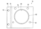
フランジ部材71は、それぞれアルミニウム合金押出材からなる2つの板状部材73,74(図9,10参照)を組み合わせて構成したものであり、板状の第1フランジ75、第2フランジ76及びこれらを連結するリブ77からなる。第1フランジ75は段差を有し、中央部78がバンパーリインフォースに当接する取付部79より後退した位置にあり、いずれも平板状の中央部78と外側の取付部79が互いに平行で、傾斜部81でつながれ、前記中央部78に軸部材72を取り付けるための穴82が形成されている。第2フランジ76には段差がなく、全体がサイドメンバーに当接する取付部に相当し、そのほぼ中央に軸部材72を取り付けるためのバーリング穴83が形成されている。また、バーリング穴83の周囲には穴フランジ80が形成されている。穴82,83は、いずれも第2フランジ76に対し垂直な方向にみたとき円形をなす(穴82は中央部78に対し垂直な方向にみたとき若干楕円形をなす)。
FIG. 8 shows another type of bumper stay 70. The bumper stay 70 is also disposed at an inclined end portion mounting portion (see FIG. 15) of the bumper reinforcement, and includes a flange member 71 and a shaft member 72.
The flange member 71 is configured by combining two plate-like members 73 and 74 (see FIGS. 9 and 10) each made of an aluminum alloy extruded material. The plate-like first flange 75, the second flange 76, and these It comprises a rib 77 connecting the two. The first flange 75 has a step, the central portion 78 is in a position retracted from the mounting portion 79 that contacts the bumper reinforcement, and both the flat central portion 78 and the outer mounting portion 79 are parallel to each other, and the inclined portion A hole 82 for attaching the shaft member 72 is formed in the central portion 78. The second flange 76 has no step, and corresponds to an attachment portion that abuts against the side member as a whole, and a burring hole 83 for attaching the shaft member 72 is formed at substantially the center thereof. A hole flange 80 is formed around the burring hole 83. The holes 82 and 83 are both circular when viewed in a direction perpendicular to the second flange 76 (the hole 82 is slightly elliptical when viewed in the direction perpendicular to the central portion 78).

フランジ部材71を構成する一方の部材73は、図9にも示すように、段差のある板状部材であり、外側部84と、傾斜部85を介して後退した位置にある前記中央部78からなり、該中央部78に前記穴82が形成されている。また、中央部78に作業用穴86及び作業用切り欠き87、外側部84にボルト穴88(バンパーリインフォース取付用)が形成されている。フランジ部材72を構成する他方の部材74は、図10にも示すように、一方の端部に形成された外側部89と、傾斜部91及び前記第2フランジ76からなり、該第2フランジ76に前記バーリング穴83が形成されている。また、第2フランジ76にボルト穴92(サイドメンバー取付用)、外側部89にボルト穴93が形成されている。
前記部材73,74を組み合わせてフランジ部材71を構成したとき、外側部84と外側部89が重なって前記取付部79(図8において左側の取付部79)となり、傾斜部85と傾斜部91の上端部が重なって前記傾斜部81(図8において左側の傾斜部81)となり、部材74の傾斜部91は前記リブ77となる。作業用穴86と作業用切り欠き87はちょうどサイドメンバー取付用のボルト穴92に対応する位置にきて、工具を差し入れてボルト締めができるようになっている。また、ボルト穴88とボルト穴93が重なり、図8に示すように、ここにスタッドボルト94が打ち込まれている。
As shown in FIG. 9, one member 73 constituting the flange member 71 is a plate-like member having a level difference from the outer portion 84 and the central portion 78 at a position retracted via the inclined portion 85. The hole 82 is formed in the central portion 78. Further, a work hole 86 and a work notch 87 are formed in the central portion 78, and a bolt hole 88 (for bumper reinforcement attachment) is formed in the outer portion 84. As shown in FIG. 10, the other member 74 constituting the flange member 72 includes an outer portion 89 formed at one end portion, an inclined portion 91 and the second flange 76, and the second flange 76. The burring hole 83 is formed in the upper part. Further, a bolt hole 92 (for attaching a side member) is formed in the second flange 76, and a bolt hole 93 is formed in the outer portion 89.
When the flange member 71 is configured by combining the members 73 and 74, the outer portion 84 and the outer portion 89 overlap to form the mounting portion 79 (the left-side mounting portion 79 in FIG. 8), and the inclined portion 85 and the inclined portion 91. The upper end portion overlaps to become the inclined portion 81 (left inclined portion 81 in FIG. 8), and the inclined portion 91 of the member 74 becomes the rib 77. The working hole 86 and the working notch 87 are just at positions corresponding to the bolt holes 92 for attaching the side members, and can be tightened by inserting a tool. Moreover, the bolt hole 88 and the bolt hole 93 overlap, and as shown in FIG. 8, the stud bolt 94 is driven in here.

軸部材72は、図8に示すように、各端部が穴82,83に嵌挿され、電磁成形により拡管して前記穴82,83の内周面に密着し、かつ第1フランジ75側では、穴82から前方側に突出した部分が放射方向にフランジ状に拡開して(拡開部95)、全周的に中央部78に当接し、第2フランジ76側では、軸部材72の端部が前記バーリング穴83の内周面に密着し該バーリング穴83に沿って放射方向に拡開し(拡開部96)、さらに、第1,第2フランジ75,76に挟まれた部分が電磁成形による拡管により放射方向に張り出している(張出部97)。このように、軸部材72は、両端部が穴82,83の内周面に密着し、同時に拡開部95,96と張出部97が第1フランジ75の中央部78及び第2フランジ76を挟んだかたちで、前記第1,第2フランジ75,76に固定されている。また、第1フランジ75には段差があり、段差のない第2フランジ76側では拡開部96がバーリング穴83から前方に突出していない。従って、軸部材72の先端は第1,第2フランジ75,76の取付部(取付部79と第2フランジ76自体)より後方側(内側)に位置している。   As shown in FIG. 8, each end of the shaft member 72 is inserted into the holes 82, 83, expanded by electromagnetic forming, is in close contact with the inner peripheral surface of the holes 82, 83, and the first flange 75 side. Then, the portion protruding forward from the hole 82 expands radially in the form of a flange (expanded portion 95) and contacts the central portion 78 on the entire circumference, and on the second flange 76 side, the shaft member 72 Is closely attached to the inner peripheral surface of the burring hole 83 and radially expands along the burring hole 83 (expanded portion 96), and is further sandwiched between the first and second flanges 75 and 76. The portion is projected in the radial direction by expansion by electromagnetic forming (the overhang portion 97). Thus, both ends of the shaft member 72 are in close contact with the inner peripheral surfaces of the holes 82 and 83, and at the same time, the expanded portions 95 and 96 and the overhanging portion 97 are the central portion 78 and the second flange 76 of the first flange 75. Is fixed to the first and second flanges 75 and 76. Further, the first flange 75 has a step, and the expanded portion 96 does not protrude forward from the burring hole 83 on the second flange 76 side without the step. Accordingly, the distal end of the shaft member 72 is located on the rear side (inner side) of the attachment portions (the attachment portion 79 and the second flange 76 itself) of the first and second flanges 75 and 76.

フランジ部材71に軸部材72を固定してバンパーステイ70を製造する方法を図11に示す。フランジ部材71の第1,第2フランジ75,76に形成した穴82,バーリング穴83に、軸素材90の各端部を嵌挿し、第1フランジ75側では先端を前方側に突出させる(図11の仮想線参照)。軸素材90は円形断面のアルミニウム合金押出材からなり、一端が軸方向に垂直な面で切断され、他端がその面から傾斜した面に沿って切断され、前記一端の切断面が第2フランジ76に平行、前記他端の切断面が第1フランジ75の中央部78に平行(穴82からの突出長さが周方向に均一)になるように穴82,83内に配置される。
この状態で軸素材90をフランジ部材71に対して位置決めし、軸素材90内に電磁成形用コイル体98を挿入し、フランジ部材71の開口側に変形防止用の治具99を挿入し、電気エネルギーを投入して、電磁成形を行い、軸素材90を放射方向に拡径する。これにより、先に説明したバンパーステイ70を得ることができる。
FIG. 11 shows a method for manufacturing the bumper stay 70 by fixing the shaft member 72 to the flange member 71. The end portions of the shaft blank 90 are inserted into the holes 82 and the burring holes 83 formed in the first and second flanges 75 and 76 of the flange member 71, and the front end protrudes forward on the first flange 75 side (see FIG. 11 imaginary lines). The shaft material 90 is made of an aluminum alloy extruded material having a circular cross section, one end is cut by a surface perpendicular to the axial direction, the other end is cut along a surface inclined from the surface, and the cut surface of the one end is a second flange. It is arranged in the holes 82 and 83 so that the cut surface at the other end is parallel to the center portion 78 of the first flange 75 (the protruding length from the hole 82 is uniform in the circumferential direction).
In this state, the shaft blank 90 is positioned with respect to the flange member 71, the electromagnetic forming coil body 98 is inserted into the shaft blank 90, and a deformation preventing jig 99 is inserted into the opening side of the flange member 71. Energy is input, electromagnetic forming is performed, and the diameter of the shaft material 90 is increased in the radial direction. As a result, the bumper stay 70 described above can be obtained.

このバンパーステイ70では、フランジ部材71を2つの板状の部材73,74により構成したが、これにより、一体型のフランジ部材(例えばフランジ部材21)に比べて、穴開けがしやすいという利点がある。穴開けは第1フランジ側、第2フランジ側とも、各フランジに対して穴の軸線が垂直になるように行われるが、一体型のフランジ部材の場合、両フランジの間に治具を位置決めする必要があるなど、余分な手間が掛かる。特に、中空部材21のように、第1フランジ23の穴29と第2フランジ24の穴34の軸線が異なる場合は、上下の穴開けが一度にできないという問題がある。これに対し、フランジ部材71の場合、各部材73,74が板状断面であるので、穴開けが容易である。また、押出成形も容易であり、板をプレス加工して成形できるという利点もある。   In this bumper stay 70, the flange member 71 is composed of two plate-like members 73 and 74, but this has the advantage that it is easier to make a hole than the integral flange member (for example, the flange member 21). is there. Drilling is performed so that the axis of the hole is perpendicular to each flange on both the first flange side and the second flange side. In the case of an integral flange member, a jig is positioned between both flanges. It is necessary to take extra time. In particular, when the axial lines of the hole 29 of the first flange 23 and the hole 34 of the second flange 24 are different as in the hollow member 21, there is a problem that the upper and lower holes cannot be formed at a time. On the other hand, in the case of the flange member 71, since the members 73 and 74 have a plate-like cross section, drilling is easy. Further, extrusion molding is easy, and there is an advantage that the plate can be formed by pressing.

図12に別の形態のバンパーステイ100を示す。このバンパーステイ100も、バンパーリインフォースの傾斜した端部取付箇所(図15参照)に配置されるもので、フランジ部材101(フランジ部材71と同じく2つの部材103,104からなる)と軸部材102からなる。このバンパーステイ100は、第1,第2フランジ105,106に形成された穴が、いずれも前方側からバーリング加工されたバーリング穴107,108である点で、バンパーステイ70と異なる。各バーリング穴107,108の周囲にはそれぞれ穴フランジ109,110が形成されている。   FIG. 12 shows another form of bumper stay 100. This bumper stay 100 is also disposed at an inclined end attachment location (see FIG. 15) of the bumper reinforcement, and includes a flange member 101 (consisting of two members 103 and 104 as in the flange member 71) and a shaft member 102. Become. The bumper stay 100 is different from the bumper stay 70 in that the holes formed in the first and second flanges 105 and 106 are burring holes 107 and 108 that are burred from the front side. Hole flanges 109 and 110 are formed around the burring holes 107 and 108, respectively.

軸部材102は、、各端部がバーリング穴107,108に嵌挿され、電磁成形により拡管して前記バーリング穴107,108の内周面に密着し、前記バーリング穴107,108に沿って放射方向に拡開し(拡開部111,112)、さらに、第1,第2フランジ105,106に挟まれた部分が電磁成形による拡管により放射方向に張り出している(張出部113)。第1フランジ105側では、軸部材102の先端はバーリング穴107から前方側(外側)に突出しているが、第1フランジ105は段差を有し、バーリング穴107が形成された中央部114がバンパーリインフォースに当接する取付部115より後退した位置にあるため、前記取付部115より後方側(内側)に位置している。また、段差のない第2フランジ104側では、前記バンパーステイ70における拡開部96と同様に、軸部材102の先端はバーリング穴106から前方(外側)に突出していない。   Each end of the shaft member 102 is fitted and inserted into the burring holes 107 and 108, expanded by electromagnetic forming, is in close contact with the inner peripheral surface of the burring holes 107 and 108, and radiates along the burring holes 107 and 108. Further, the portions sandwiched between the first and second flanges 105 and 106 project in the radial direction by expansion by electromagnetic forming (projecting portion 113). On the first flange 105 side, the tip of the shaft member 102 protrudes forward (outside) from the burring hole 107, but the first flange 105 has a step, and the central portion 114 where the burring hole 107 is formed is a bumper. Since it is in a position retracted from the attachment portion 115 that contacts the reinforcement, it is located on the rear side (inside) from the attachment portion 115. Further, on the second flange 104 side without a step, the tip of the shaft member 102 does not protrude forward (outside) from the burring hole 106, as with the expanded portion 96 in the bumper stay 70.

図13(b)に、前記バンパーステイ100における部材103の変形例として、部材116を示す。部材116では、中央部117に形成されたバーリング穴の周囲に穴フランジ118が形成され、該穴フランジ118に複数個の縦方向のスリット119が形成されている。スリット119を有する穴フランジ118は、図13(a)に示すように、部材116の中央部117に形成された下穴120の縁に放射方向にスリット121を形成し、次いでこの下穴120にバーリング加工を施すことにより成形することができる。このスリット119があることにより、バーリング穴に軸素材を嵌挿して電磁成形により拡管したとき、成形された軸部材102(図12参照9)がスリット119内に張り出し、軸部材102とバーリング穴の固定(特に回り止め)がより確実となる。   FIG. 13B shows a member 116 as a modified example of the member 103 in the bumper stay 100. In the member 116, a hole flange 118 is formed around a burring hole formed in the central portion 117, and a plurality of longitudinal slits 119 are formed in the hole flange 118. The hole flange 118 having the slit 119 forms a slit 121 in the radial direction at the edge of the pilot hole 120 formed in the central portion 117 of the member 116 as shown in FIG. It can be formed by burring. Due to the presence of the slit 119, when the shaft material is inserted into the burring hole and expanded by electromagnetic forming, the formed shaft member 102 (see FIG. 12) projects into the slit 119, and the shaft member 102 and the burring hole Fixing (especially anti-rotation) is more reliable.

図14は、前記バンパーステイ100における部材103の変形例として、部材123とそのバーリング穴の加工法を示すものである。部材103では、バーリング加工は中央部78の面に対して垂直に行われ、穴フランジ109の軸も中央部78の面に対して垂直に形成されていた。これに対し、部材123の場合、下穴形成後、図14に示すようにダイス124上に傾斜して置き、その上を板押さえ125で押さえ、下穴にポンチ126を圧入する。従って、バーリング加工は中央部127の面に対して傾斜して行われ、バーリング穴の周囲に形成された穴フランジ128の中心軸は中央部127の面に対して傾斜している。この傾斜は軸部材(及び軸素材)に対する第1フランジ(中央部126)の傾斜と一致するように、すなわち、穴フランジ127の中心軸が軸部材(及び軸素材)の中心軸に対して平行になるように設定される。穴フランジ128と軸素材の中心軸の方向が揃うので、電磁成形時に、軸素材をバーリング穴に正確に嵌め込むことができる。   FIG. 14 shows a member 123 and a burring hole machining method as a modification of the member 103 in the bumper stay 100. In the member 103, the burring process is performed perpendicular to the surface of the central portion 78, and the axis of the hole flange 109 is also formed perpendicular to the surface of the central portion 78. On the other hand, in the case of the member 123, after forming the prepared hole, it is inclined and placed on the die 124 as shown in FIG. 14, the upper part is pressed by the plate holder 125, and the punch 126 is press-fitted into the prepared hole. Therefore, the burring process is performed with an inclination with respect to the surface of the central portion 127, and the central axis of the hole flange 128 formed around the burring hole is inclined with respect to the surface of the central portion 127. This inclination matches the inclination of the first flange (center portion 126) with respect to the shaft member (and shaft material), that is, the center axis of the hole flange 127 is parallel to the center axis of the shaft member (and shaft material). Is set to be Since the directions of the hole flange 128 and the central axis of the shaft material are aligned, the shaft material can be accurately fitted into the burring hole during electromagnetic forming.

本発明に係るバンパーステイの斜視図である。It is a perspective view of the bumper stay concerning the present invention. そのバンパーステイを構成するフランジ部材の斜視図である。It is a perspective view of the flange member which comprises the bumper stay. そのバンパーステイの製造方法を説明する断面図である。It is sectional drawing explaining the manufacturing method of the bumper stay. 図1のI−I断面図である。It is II sectional drawing of FIG. 図1のII−II断面図である。It is II-II sectional drawing of FIG. 本発明に係る別のバンパーステイの断面図である。It is sectional drawing of another bumper stay which concerns on this invention. 図6のIII−III断面図である。It is III-III sectional drawing of FIG. 本発明に係るさらに別のバンパーステイの斜視図である。It is a perspective view of another bumper stay concerning the present invention. そのバンパーステイのフランジ部材部材を構成する一方の部材の平面図である。It is a top view of one member which comprises the flange member member of the bumper stay. そのバンパーステイのフランジ部材を構成する他方の部材の平面図である。It is a top view of the other member which comprises the flange member of the bumper stay. そのバンパーステイの製造方法を説明する断面図である。It is sectional drawing explaining the manufacturing method of the bumper stay. 本発明に係るさらに別のバンパーステイの断面図である。It is sectional drawing of another bumper stay which concerns on this invention. 図12に示すバンパーステイのフランジ部材を構成する部材の別の形態のもののバーリング加工前の平面図(a)、及びバーリング加工後の側面図(b)である。It is the top view (a) before burring process of the thing of another form of the member which comprises the flange member of a bumper stay shown in FIG. 12, and the side view (b) after burring process. 図12に示すバンパーステイのフランジ部材を構成する部材の別の形態のものの断面図である。It is sectional drawing of the thing of another form of the member which comprises the flange member of the bumper stay shown in FIG. 種々のタイプ(型)のバンパーステイを説明する図である。It is a figure explaining the bumper stay of various types (form).

符号の説明Explanation of symbols

20,50,70,100 バンパーステイ
21,51,71,101 フランジ部材
22,52,72,102 軸部材
23,53,75,105 第1フランジ
24,54,76,106 第2フランジ
25,55,75 リブ
29,34、61,62,82 穴
37,38,63,64,95,96,111,112 拡開部
39,97,113 張出部
73,74,103,104,116,123 板状部材
80,109,118,128 穴フランジ
83,107 バーリング穴
20, 50, 70, 100 Bumper stay 21, 51, 71, 101 Flange member 22, 52, 72, 102 Shaft member 23, 53, 75, 105 First flange 24, 54, 76, 106 Second flange 25, 55 , 75 Rib 29, 34, 61, 62, 82 Hole 37, 38, 63, 64, 95, 96, 111, 112 Expanded part 39, 97, 113 Overhang part 73, 74, 103, 104, 116, 123 Plate member 80, 109, 118, 128 Hole flange 83, 107 Burring hole

Claims (20)

他部材の被取付部に当接する取付部を有する板状のフランジと、管状のアルミニウム合金押出材からなり端部が前記フランジに固定された軸部材により構成され、前記フランジに穴が形成され、前記軸部材の端部が前記穴に嵌挿され、電磁成形により拡管して前記穴の内周面に密着し、かつ前記軸部材の先端が前記フランジの穴から前方側に突出して放射方向に拡開し、さらに前記フランジに段差が形成されていて前記フランジの前記穴が形成された箇所が前記取付部より後退した位置にあり、かつ前記軸部材の先端が前記フランジの取付部と同一面上又はそれより後方側に位置することを特徴とする接続構造体。 A plate-like flange having a mounting portion that comes into contact with a mounted portion of another member, and a shaft member made of a tubular aluminum alloy extruded material and having an end fixed to the flange, and a hole is formed in the flange, The end of the shaft member is inserted into the hole, expanded by electromagnetic forming, closely attached to the inner peripheral surface of the hole, and the tip of the shaft member protrudes forward from the hole of the flange in the radial direction. The flange is further widened and a step is formed in the flange, and the portion where the hole is formed in the flange is in a position retracted from the mounting portion, and the tip of the shaft member is flush with the mounting portion of the flange A connection structure located above or behind the connection structure. 前記穴が前方側からバーリング加工されたバーリング穴であることを特徴とする請求項1に記載された接続構造体。 The connection structure according to claim 1, wherein the hole is a burring hole formed by burring from the front side. 他部材の被取付部に当接する取付部を有する板状のフランジと、管状のアルミニウム合金押出材からなり端部が前記フランジに固定された軸部材により構成され、前記フランジに穴が形成され、前記穴が前方側からバーリング加工されたバーリング穴であり、前記軸部材の端部が前記穴に嵌挿され、電磁成形により拡管して前記バーリング穴の内周面に密着し、かつ前記内周面に沿って放射方向に拡開し、さらに前記軸部材の先端が前記バーリング穴より前方に突出せず、前記フランジの取付部と同一面上又はそれより後方側に位置することを特徴とする接続構造体。 A plate-like flange having a mounting portion that comes into contact with a mounted portion of another member, and a shaft member made of a tubular aluminum alloy extruded material and having an end fixed to the flange, and a hole is formed in the flange, The hole is a burring hole that is burring processed from the front side, the end of the shaft member is fitted into the hole, and is expanded by electromagnetic forming to closely contact the inner peripheral surface of the burring hole. The front end of the shaft member does not protrude forward from the burring hole, and is located on the same plane as the flange mounting portion or on the rear side thereof. Connection structure. それぞれ他部材の被取付部に当接する取付部を有し互いに間隔を開けて配置された一対の板状のフランジと、管状のアルミニウム合金押出材からなり各端部が各フランジに固定された軸部材により構成され、各フランジに穴が形成され、前記軸部材の各端部が前記穴に嵌挿され、電磁成形により拡管して前記穴の内周面に密着し、さらに少なくとも一方のフランジにおいて、前記フランジに段差が形成されていて前記穴が形成された箇所が前記取付部より後退した位置にあり、前記軸部材の先端が前記一方のフランジに形成された穴から前方側に突出して電磁成形により放射方向に拡開し、かつ前記軸部材の先端が前記一方のフランジの取付部と同一面上又はそれより後方側に位置することを特徴とする接続構造体。 A pair of plate-like flanges each having a mounting portion that abuts against a mounted portion of another member and spaced apart from each other, and a shaft made of a tubular aluminum alloy extruded material, each end portion being fixed to each flange Each of the flanges is formed with a hole, and each end of the shaft member is fitted into the hole, expanded by electromagnetic forming, closely attached to the inner peripheral surface of the hole, and at least one of the flanges The portion where the flange is formed and the hole is formed is in a position retracted from the mounting portion, and the tip of the shaft member projects forward from the hole formed in the one flange. A connection structure characterized in that it expands in the radial direction by molding, and the tip of the shaft member is located on the same plane as the mounting portion of the one flange or on the rear side thereof. 前記一方のフランジに形成された穴が前方側からバーリング加工されたバーリング穴であることを特徴とする請求項4に記載された接続構造体。 The connection structure according to claim 4, wherein the hole formed in the one flange is a burring hole formed by burring from the front side. それぞれ他部材の被取付部に当接する取付部を有し互いに間隔を開けて配置された一対の板状のフランジと、管状のアルミニウム合金押出材からなり各端部が各フランジに固定された軸部材により構成され、各フランジに穴が形成され、前記軸部材の各端部が前記穴に嵌挿され、電磁成形により拡管して前記穴の内周面に密着し、さらに少なくとも一方のフランジにおいて、前記穴が前方側からバーリング加工されたバーリング穴であり、前記軸部材の端部が前記バーリング穴の内周面に沿って放射方向に拡開し、かつ前記軸部材の先端が前記バーリング穴より前方に突出せず、前記フランジの取付部と同一面上又はそれより後方側に位置することを特徴とする接続構造体。 A pair of plate-like flanges each having a mounting portion that abuts against a mounted portion of another member and spaced apart from each other, and a shaft made of a tubular aluminum alloy extruded material, each end portion being fixed to each flange Each of the flanges is formed with a hole, and each end of the shaft member is fitted into the hole, expanded by electromagnetic forming, closely attached to the inner peripheral surface of the hole, and at least one of the flanges The hole is a burring hole formed by burring from the front side, the end of the shaft member expands radially along the inner peripheral surface of the burring hole, and the tip of the shaft member is the burring hole A connection structure characterized in that the connection structure does not protrude further forward and is located on the same plane as the mounting portion of the flange or on the rear side. それぞれ他部材の被取付部に当接する取付部を有し互いに間隔を開けて配置された一対の板状のフランジ、及び両フランジを連結する1つのリブからなるフランジ部材と、管状のアルミニウム合金押出材からなり各端部が各フランジに固定された軸部材により構成され、各フランジに穴が形成され、前記軸部材の各端部が前記穴に嵌挿され、電磁成形により拡管して前記穴の内周面に密着し、さらに少なくとも一方のフランジにおいて、前記フランジに段差が形成されていて前記穴が形成された箇所が前記取付部より後退した位置にあり、前記軸部材の先端が前記一方のフランジに形成された穴から前方側に突出して電磁成形により放射方向に拡開し、かつ前記軸部材の先端が前記一方のフランジの取付部と同一面上又はそれより後方側に位置することを特徴とする接続構造体。 A flange member composed of a pair of plate-like flanges each having an attachment portion that abuts against an attachment portion of another member and spaced from each other, and a rib member that connects both flanges, and tubular aluminum alloy extrusion Each end is made up of a shaft member made of a material and fixed to each flange, a hole is formed in each flange, each end of the shaft member is inserted into the hole, and expanded by electromagnetic forming to form the hole. And at least one of the flanges has a step formed in the flange and the position where the hole is formed is in a position retracted from the mounting portion, and the tip of the shaft member is the one of the one flange It protrudes forward from the hole formed in the flange of the flange and expands in the radial direction by electromagnetic forming, and the tip of the shaft member is on the same plane as the mounting portion of the one flange or on the rear side thereof Connection structure characterized by. 前記一方のフランジに形成された穴が前方側からバーリング加工されたバーリング穴であることを特徴とする請求項7に記載された接続構造体。 The connection structure according to claim 7, wherein the hole formed in the one flange is a burring hole that is burring processed from the front side. それぞれ他部材の被取付部に当接する取付部を有し互いに間隔を開けて配置された一対の板状のフランジ、及び両フランジを連結する1つのリブからなるフランジ部材と、管状のアルミニウム合金押出材からなり各端部が各フランジに固定された軸部材により構成され、各フランジに穴が形成され、前記軸部材の各端部が前記穴に嵌挿され、電磁成形により拡管して前記穴の内周面に密着し、さらに少なくとも一方のフランジにおいて、前記穴が前方側からバーリング加工されたバーリング穴であり、前記軸部材の端部が前記バーリング穴の内周面に沿って放射方向に拡開し、かつ前記軸部材の先端が前記バーリング穴より前方に突出せず、前記フランジの取付部と同一面上又はそれより後方側に位置することを特徴とする接続構造体。 A flange member composed of a pair of plate-like flanges each having an attachment portion that abuts against an attachment portion of another member and spaced from each other, and a rib member that connects both flanges, and tubular aluminum alloy extrusion Each end is made up of a shaft member made of a material and fixed to each flange, a hole is formed in each flange, each end of the shaft member is inserted into the hole, and expanded by electromagnetic forming to form the hole. Further, in at least one of the flanges, the hole is a burring hole in which burring is performed from the front side, and an end portion of the shaft member is radially formed along the inner peripheral surface of the burring hole. The connection structure is characterized in that it expands and the front end of the shaft member does not protrude forward from the burring hole and is located on the same plane as the mounting portion of the flange or on the rear side. 他部材の被取付部に当接する取付部を有する板状のフランジと、管状のアルミニウム合金押出材からなり端部が前記フランジに固定された軸部材により構成され、前記フランジに穴が形成され、前記穴が前方側からバーリング加工されたバーリング穴であり、前記フランジの前記バーリング穴が形成された箇所が、前記軸部材の軸方向に対し垂直な面から傾斜し、かつ前記バーリング穴の周囲に形成された穴フランジの中心軸が前記軸部材の中心軸に対して平行とされ、前記軸部材の端部が前記穴に嵌挿され、電磁成形により拡管して前記バーリング穴の内周面に密着し、かつ前記内周面に沿って放射方向に拡開し、さらに前記軸部材の先端が前記バーリング穴より前方に突出せず、前記フランジの取付部と同一面上又はそれより後方側に位置することを特徴とする接続構造体。A plate-like flange having a mounting portion that comes into contact with a mounted portion of another member, and a shaft member made of a tubular aluminum alloy extruded material and having an end fixed to the flange, and a hole is formed in the flange, The hole is a burring hole formed by burring from the front side, and the portion of the flange where the burring hole is formed is inclined from a plane perpendicular to the axial direction of the shaft member, and around the burring hole. The center axis of the formed hole flange is parallel to the center axis of the shaft member, and the end of the shaft member is inserted into the hole and expanded by electromagnetic forming to the inner peripheral surface of the burring hole. It closely adheres and expands radially along the inner peripheral surface, and further, the tip of the shaft member does not protrude forward from the burring hole, and is on the same plane as the mounting portion of the flange or on the rear side thereof. Place Connection structure characterized by. 前記軸部材の前記フランジの穴より後方側が電磁成形による拡管により放射方向に張り出していることを特徴とする請求項1〜10のいずれかに記載された接続構造体。 The connection structure according to any one of claims 1 to 10 , wherein a rear side of the shaft member from the hole of the flange projects radially by pipe expansion by electromagnetic forming. 前記軸部材の両フランジに挟まれた部分が電磁成形による拡管により放射方向に張り出していることを特徴とする請求項4〜9のいずれかに記載された接続構造体。 The connection structure according to any one of claims 4 to 9, wherein a portion sandwiched between both flanges of the shaft member projects in a radial direction by pipe expansion by electromagnetic forming. 前記フランジが、長さ方向に垂直な面内での断面形状が同一なアルミニウム合金形材からなることを特徴とする請求項1〜6,10のいずれかに記載された接続構造体。 The connection structure according to any one of claims 1 to 6 , wherein the flange is made of an aluminum alloy profile having the same cross-sectional shape in a plane perpendicular to the length direction. 前記フランジが押出材からなることを特徴とする請求項13に記載された接続構造体。 The connection structure according to claim 13 , wherein the flange is made of an extruded material. 前記フランジ部材が、長さ方向に垂直な面内での断面形状が同一なアルミニウム合金形材からなることを特徴とする請求項7〜9のいずれかに記載された接続構造体。 The connection structure according to any one of claims 7 to 9, wherein the flange member is made of an aluminum alloy profile having the same cross-sectional shape in a plane perpendicular to the length direction. 前記フランジ部材が押出材からなることを特徴とする請求項15に記載された接続構造体。 The connection structure according to claim 15 , wherein the flange member is made of an extruded material. 前記フランジ部材が複数個の部材を組み合わせてなることを特徴とする請求項7〜9,15,16のいずれかに記載された接続構造体。 Claim 7-9, connection structure according to any one of 15, 16, wherein said flange member is formed by combining a plurality of members. 前記フランジの前記穴が形成された箇所が、前記軸部材の軸方向に対し垂直な面から傾斜していることを特徴とする請求項1〜3のいずれかに記載された接続構造体。 The connection structure according to claim 1, wherein a portion of the flange where the hole is formed is inclined from a plane perpendicular to the axial direction of the shaft member. 前記両フランジの少なくとも一方において、前記穴が形成された箇所が、前記軸部材の軸方向に対し垂直な面から傾斜していることを特徴とする請求項4〜9のいずれかに記載された接続構造体。 The location where the hole is formed in at least one of the two flanges is inclined from a plane perpendicular to the axial direction of the shaft member. Connection structure. 前記接続構造体がバンパーステイであって、前記フランジが車体の上下方向に垂直な面内での断面形状が実質的に同一なアルミニウム合金形材からなり、バンパーリインフォースがいずれか一方のフランジの取付部に固定され、サイドメンバが他方のフランジの取付部に固定されることを特徴とする請求項4〜9のいずれかに記載された接続構造体。 The connection structure is a bumper stay, and the flange is made of an aluminum alloy material having substantially the same cross-sectional shape in a plane perpendicular to the vertical direction of the vehicle body, and the bumper reinforcement is attached to one of the flanges. The connection structure according to any one of claims 4 to 9, wherein the connection member is fixed to the portion and the side member is fixed to the attachment portion of the other flange.
JP2004302574A 2004-04-27 2004-10-18 Connection structure Expired - Lifetime JP3939323B2 (en)

Priority Applications (3)

Application Number Priority Date Filing Date Title
JP2004302574A JP3939323B2 (en) 2004-10-18 2004-10-18 Connection structure
US11/115,353 US7658421B2 (en) 2004-04-27 2005-04-27 Axial member with flange, connection member and production methods thereof
US12/650,146 US7980615B2 (en) 2004-04-27 2009-12-30 Axial member with flange, connection member and production methods thereof

Applications Claiming Priority (1)

Application Number Priority Date Filing Date Title
JP2004302574A JP3939323B2 (en) 2004-10-18 2004-10-18 Connection structure

Publications (2)

Publication Number Publication Date
JP2006110609A JP2006110609A (en) 2006-04-27
JP3939323B2 true JP3939323B2 (en) 2007-07-04

Family

ID=36379551

Family Applications (1)

Application Number Title Priority Date Filing Date
JP2004302574A Expired - Lifetime JP3939323B2 (en) 2004-04-27 2004-10-18 Connection structure

Country Status (1)

Country Link
JP (1) JP3939323B2 (en)

Families Citing this family (9)

* Cited by examiner, † Cited by third party
Publication number Priority date Publication date Assignee Title
JP4895739B2 (en) * 2006-09-16 2012-03-14 株式会社神戸製鋼所 Bumper structure
JP5311730B2 (en) * 2006-09-21 2013-10-09 株式会社神戸製鋼所 Bumper structure
JP5177397B2 (en) * 2008-03-31 2013-04-03 株式会社神戸製鋼所 Bumper structure
JP5177417B2 (en) * 2008-11-14 2013-04-03 株式会社神戸製鋼所 Bumper structure and method for manufacturing bumper structure
JP5355048B2 (en) * 2008-11-17 2013-11-27 株式会社神戸製鋼所 Manufacturing method of bonded structure
JP5794944B2 (en) * 2012-03-29 2015-10-14 三菱重工業株式会社 Tube expansion method
JP6767907B2 (en) * 2017-03-27 2020-10-14 株式会社神戸製鋼所 Joining method and equipment of members
JP6916056B2 (en) * 2017-07-12 2021-08-11 トヨタ自動車株式会社 Instrument panel reinforcement fixed structure
JP6978263B2 (en) * 2017-09-25 2021-12-08 東プレ株式会社 How to make hot pressed products

Also Published As

Publication number Publication date
JP2006110609A (en) 2006-04-27

Similar Documents

Publication Publication Date Title
US7980615B2 (en) Axial member with flange, connection member and production methods thereof
JP4737768B2 (en) Detachable tow hook mounting structure
JP4895739B2 (en) Bumper structure
EP2412584B1 (en) Bumper device for vehicle
JP2007284039A (en) Bumper structure and frame structure
US7896408B2 (en) Bumper structure
US10005436B2 (en) Brake pedal apparatus for a vehicle
JP3939323B2 (en) Connection structure
JP5564005B2 (en) Detachable tow hook mounting structure
EP1979183B1 (en) Manufacturing method of an automobile impact beam with integrated brackets
JP5311730B2 (en) Bumper structure
JP4664103B2 (en) Steering support beam and manufacturing method thereof
JP5049210B2 (en) Bumper stay
JP2009274635A (en) Bumper structure
JP4111943B2 (en) Bumper stay
JP6000888B2 (en) Mounting structure for the joint reinforcement collar
JP2013159153A (en) Bumper structure
JP5300936B2 (en) Bumper structure
JP4297213B2 (en) Manufacturing method of tubular member with flange
JP6619654B2 (en) Manufacturing method of pipe with bracket
JP4463057B2 (en) Automotive bumper stay
JP4459220B2 (en) Manufacturing method of tubular member with flange
JP2018062213A (en) Steering device
JP4413057B2 (en) Manufacturing method of shaft member with flange and shaft member with flange
JP2010051978A (en) Method of joining members to each other, steering support beam, and joined structure

Legal Events

Date Code Title Description
A977 Report on retrieval

Free format text: JAPANESE INTERMEDIATE CODE: A971007

Effective date: 20061026

A131 Notification of reasons for refusal

Free format text: JAPANESE INTERMEDIATE CODE: A131

Effective date: 20061107

A521 Request for written amendment filed

Free format text: JAPANESE INTERMEDIATE CODE: A523

Effective date: 20061213

TRDD Decision of grant or rejection written
A01 Written decision to grant a patent or to grant a registration (utility model)

Free format text: JAPANESE INTERMEDIATE CODE: A01

Effective date: 20070327

A61 First payment of annual fees (during grant procedure)

Free format text: JAPANESE INTERMEDIATE CODE: A61

Effective date: 20070327

R150 Certificate of patent or registration of utility model

Ref document number: 3939323

Country of ref document: JP

Free format text: JAPANESE INTERMEDIATE CODE: R150

Free format text: JAPANESE INTERMEDIATE CODE: R150

FPAY Renewal fee payment (event date is renewal date of database)

Free format text: PAYMENT UNTIL: 20100406

Year of fee payment: 3

FPAY Renewal fee payment (event date is renewal date of database)

Free format text: PAYMENT UNTIL: 20110406

Year of fee payment: 4

FPAY Renewal fee payment (event date is renewal date of database)

Free format text: PAYMENT UNTIL: 20120406

Year of fee payment: 5

FPAY Renewal fee payment (event date is renewal date of database)

Free format text: PAYMENT UNTIL: 20130406

Year of fee payment: 6

FPAY Renewal fee payment (event date is renewal date of database)

Free format text: PAYMENT UNTIL: 20130406

Year of fee payment: 6

FPAY Renewal fee payment (event date is renewal date of database)

Free format text: PAYMENT UNTIL: 20140406

Year of fee payment: 7

EXPY Cancellation because of completion of term