JP3937684B2 - Tactile presentation device - Google Patents
Tactile presentation device Download PDFInfo
- Publication number
- JP3937684B2 JP3937684B2 JP2000119614A JP2000119614A JP3937684B2 JP 3937684 B2 JP3937684 B2 JP 3937684B2 JP 2000119614 A JP2000119614 A JP 2000119614A JP 2000119614 A JP2000119614 A JP 2000119614A JP 3937684 B2 JP3937684 B2 JP 3937684B2
- Authority
- JP
- Japan
- Prior art keywords
- tactile sensation
- information
- tactile
- reproduction
- magnetic field
- Prior art date
- Legal status (The legal status is an assumption and is not a legal conclusion. Google has not performed a legal analysis and makes no representation as to the accuracy of the status listed.)
- Expired - Fee Related
Links
- 230000035807 sensation Effects 0.000 claims description 108
- 238000006243 chemical reaction Methods 0.000 claims description 14
- 238000006073 displacement reaction Methods 0.000 claims description 11
- 238000000034 method Methods 0.000 description 12
- 238000010586 diagram Methods 0.000 description 6
- 238000004891 communication Methods 0.000 description 4
- 238000001514 detection method Methods 0.000 description 3
- 239000002783 friction material Substances 0.000 description 2
- 230000010365 information processing Effects 0.000 description 2
- 239000010687 lubricating oil Substances 0.000 description 2
- 230000015541 sensory perception of touch Effects 0.000 description 2
- 230000002194 synthesizing effect Effects 0.000 description 2
- 230000000007 visual effect Effects 0.000 description 2
- 125000002066 L-histidyl group Chemical group [H]N1C([H])=NC(C([H])([H])[C@](C(=O)[*])([H])N([H])[H])=C1[H] 0.000 description 1
- 230000000295 complement effect Effects 0.000 description 1
- 125000004122 cyclic group Chemical group 0.000 description 1
- 230000003247 decreasing effect Effects 0.000 description 1
- 210000005069 ears Anatomy 0.000 description 1
- 230000000694 effects Effects 0.000 description 1
- 230000007613 environmental effect Effects 0.000 description 1
- 239000012530 fluid Substances 0.000 description 1
- 230000001771 impaired effect Effects 0.000 description 1
- 238000004519 manufacturing process Methods 0.000 description 1
- 239000002184 metal Substances 0.000 description 1
- 210000000056 organ Anatomy 0.000 description 1
- 230000008447 perception Effects 0.000 description 1
- -1 polytetrafluoroethylene Polymers 0.000 description 1
- 229920001343 polytetrafluoroethylene Polymers 0.000 description 1
- 239000004810 polytetrafluoroethylene Substances 0.000 description 1
- 239000011347 resin Substances 0.000 description 1
- 229920005989 resin Polymers 0.000 description 1
- 238000005096 rolling process Methods 0.000 description 1
- 230000001953 sensory effect Effects 0.000 description 1
- 238000004804 winding Methods 0.000 description 1
Images


Landscapes
- Controls And Circuits For Display Device (AREA)
- User Interface Of Digital Computer (AREA)
Description
【0001】
【発明の属する技術分野】
本発明は、触感呈示装置に係り、特に、情報処理装置におけるいわゆるGUI(グラフィカル・ユーザー・インターフェイス)において、情報処理装置呈示部に表示される物体を触れたりなぞったりしたときに感じ取る触感を擬似的に呈示する触感呈示装置に関する。
【0002】
【従来の技術】
一般に、目、耳、鼻、手、指などの受容器官を用いて知覚する体感情報の中で、対象物を認知して特定の判断を下す場合に、触感から得られる情報が最終的に判断の決め手となる場合が多い。つまり、対象物に手や指で触れることによって、粗滑感や凹凸感等の対象物の表面情報を理解して様々な判断を下している。
【0003】
ところで近年、インターネットやゲーム機などのように情報機器及び通信情報機器の急激な普及により、パソコンやテレビ等の表示装置の画面上に表示されて視覚情報に依存する情報、例えば、商品や展示物などの情報、あるいは雑誌やパンフレット、カタログなどの文書で紹介される商品などの情報が増加しつつある。
【0004】
これらの情報機器及び通信情報機器からの情報は、画面上の表示だけであり、言語的、視覚的に訴えるものである。そのため、ユーザは言語的、視覚的に対象を認識することができるが、雰囲気や体感を感じ取ることは困難である。従って、ユーザは自らの経験に基づいてこれらの情報の欠落部分を推測、補完して理解する必要がある。
【0005】
また、インターネットやゲーム機など主に視覚情報に依存する情報通信機器の普及が進むにつれ、利用者の要求も高くなりつつある。そのため、将来的には情報通信機器上で画像として表示された触れることができない物体をなぞったときの触感を擬似的に得る要求が生じることが予想される。
【0006】
触感を擬似的に得るための手段として、例えば、特開平11−10561号公報、特開平11−33937号公報、及び特開平9−155785号公報等が提案されている。
【0007】
特開平11−10561号公報には、曲面や平面、凸エッジを有するヘッドを有する物体形状提示手段を複数備え、操作者が呈示したい形状に応じて物体形状提示ヘッドを選択することにより操作者の指先に物体形状を提示する構成の物体形状提示装置が提案されている。
【0008】
また、特開平11−33937号公報には、凸エッジや凹エッジ、凸曲面、凹曲面、そして平面を有する環境提示ツールを備え、環境操作者が呈示したい形状に応じて提示ツールの面を選択することにより物体形状を提示する力触覚ディスプレイ方法が提案されている。
【0009】
さらに、特開平9−155785号公報には、対象物との接触状態を検出する検出手段からの信号を処理し、最終的に人に知覚し得る触知覚情報に変換してユーザに伝達する触感呈示装置が提案されている。
【0010】
【発明が解決しようとする課題】
しかしながら、特開平11−10561号公報及び特開平11−33937号公報に示された物体形状呈示装置は、対象物体の表面形状や変形状態を正確に提示するものであるので、事前に呈示したい触感形状に応じた多数多種類の物体形状呈示ヘッドもしくは環境呈示ツールを用意しておかなくてはならず、装置が複雑化してしまう。また、予め用意した物体形状呈示ヘッドもしくは環境呈示ツールによる触感の再現であるため、呈示できる触感の種類が制限されてしまうという難点もある。
【0011】
さらに、特開平11−33937号公報では、触覚呈示装置の検出手段部に触感を提示したい対象物を設置する必要がある。それゆえ、遠隔にある物体の触感を呈示する場合、検出手段部のところまで赴いて対象物を設置しなくてはならず、設置の自由度が損なわれるという難点もある。
【0012】
また、特開平9−155785号公報に示された物体形状呈示装置は、ボタン状の信号呈示部位に指が置かれた状態で、人の知覚特性に対応した任意波形の信号に基づいてボイスコイルモータを駆動して、信号呈示部位を機械的に振動させて人に伝達する構成であるため、対象物体の表面をなぞったときの触感を再現できない、という問題がある。
【0013】
以上のことから、本発明は、多種多様の物体の表面をなぞったときの触感を再現することが可能な触感呈示装置を提供することを目的とする。
【0014】
【課題を解決するための手段】
上記目的を達成するために請求項1に記載の発明は、接触したときの触感を再現する触感再現対象物を表示する表示手段と、前記表示手段に表示された触感再現対象物を選択する選択手段と、前記選択手段により選択された触感再現対象物の特徴量に基づいて、予め記憶された基準の触感情報を修正して該触感再現対象物の触感情報を生成する情報生成手段と、磁界を発生させる磁界発生部、及び電流を通過させることにより、前記磁界発生部により発生された磁界によって水平面内の各々異なる方向に推力を発生させるように配置された複数のコイルを備え、使用者の触感を得られる部位が載置される推力発生部から構成され、前記複数のコイルにより発生した推力を合成した方向に前記推力発生部を水平方向に移動させて前記選択手段により選択された触感再現対象物の触感を再現して呈示する呈示手段と、前記情報生成手段が生成した触感情報に基づいて、前記コイル毎に、供給する電流の流れ方向及び大きさを制御して、前記コイル毎の推力を調整する制御手段と、を備えているものである。
【0015】
請求項1に記載の触感呈示装置は、表示手段に表示され、選択手段により選択された触感再現対象物の表面を選択手段によりなぞったときに、情報生成手段が生成した前記触感再現対象物の触感情報に基づいて呈示手段が複数のコイルにより発生した推力を合成した方向に推力発生部を水平方向に移動させて触感再現対象物から受ける触感を再現して呈示する。
【0016】
情報生成手段は、触感再現対象物の特徴量(言い換えると、基準の触感情報に対するずれ量)に応じて基準の触感情報を修正することにより前記触感再現対象物の触感情報を生成し、呈示手段は前記情報生成手段が生成した触感再現対象物の触感情報に基づいて複数のコイルにより発生した推力を合成した方向に前記推力発生部を水平方向に移動させることにより前記触感再現対象物の触感を再現して呈示する。すなわち、請求項1に記載の触感呈示装置では、触感再現対象物の特徴量という少ない情報を入力するだけで種々多様な触感を再現することが可能である。
【0017】
また、請求項2に記載したように、前記情報生成手段が予め定められた複数の分類毎に基準の触感情報を記憶しており、前記選択手段により選択された触感再現対象物が属する分類と同じ分類の基準の触感情報を選択して前記触感再現対象物の触感情報を生成するようにすると良い。
【0018】
例えば、表面に微細な凹凸が多数ある触感再現対象物、表面に凹凸がほとんどなく平滑な表面を備えた触感再現対象物、振幅の大きい凹凸面を備えている触感再現対象物等、表面形状の差が大きく触感情報に大きな差がある複数の触感再現対象物毎に標準の触感情報を作成しておくことにより、特徴量から触感情報を生成する際の計算量を少なくすることができるので、最終的に得られる触感情報に含まれる誤差を小さくすることができる。従って、より実物に近い触感を再現することができる。
【0019】
なお、触感の再現を行う呈示手段としては、例えば、磁界を発生させる磁界発生部、及び電流を通過させることにより、前記磁界発生部により発生された磁界によって水平面内の各々異なる方向に推力を発生させるように配置された複数のコイルを備え、使用者の触感を得られる部位が載置される推力発生部から構成され、前記複数のコイルにより発生した推力を合成した方向に前記推力発生部を水平方向に移動させて前記選択手段により選択された触感再現対象物の触感を再現して呈示する構成のものを用いることができる。
【0020】
なお、磁界発生部は1つに限らず、呈示手段に複数の磁界発生部を設けて、制御手段が各々の磁界発生部に対して供給する電流の流れ方向及び大きさを制御する構成とすることができる。このように構成することにより、より複雑な負荷の再現を実現することができる。
【0021】
また、基準の触感情報は、既知の表面形状の物体をなぞったときの被接触物の移動量に対応して被接触物が受ける物体からの反力及び物体に触れたときの上下変動量等の物理的現象を電気的な触感情報に変換したものであり、例えば、請求項3に記載したように、被接触物の移動量に対応する物体からの反力及び上下変動量を組み合わせたデジタルデータやアナログデータなどの電気信号とすることができる。
【0022】
また、特徴量は、前記既知の表面形状の物体に対する形状変化量であり、例えば、請求項4に記載したように、物体表面を構成する形状の高さ、物体寸法、及び物体表面の凹凸の比率の少なくとも1つにより表わすことができる。なお、特徴量は、前記形状変化量に応じて呈示変化する呈示手段の駆動信号の変化量としてもよい。
【0023】
さらに、基準の触感情報は、外部から入力されたものとしても良いし、請求項5に記載したように、請求項1から請求項4の何れか1項に記載の触感呈示装置が予め定めた形状の接触子により予め表面形状が決定された基準対象物の表面を摺動したときに前記接触子が受ける反力及び上下変位量を基準の触感情報として入力する触感情報入力手段をさらに備えるように、構成し、前記接触子が実際に受けた物理現象を電気情報に変換して基準の触感情報として入力するように構成することもできる。
【0024】
なお、前記接触子の上下変位量は、例えば、変位計等の変位量検出手段により検出することができるが、請求項6に記載したように、前記触感情報入力手段は、前記接触子先端部の変形状態、前記基準対象物表面の凹み状態、及び前記接触子先端部と前記基準対象物表面の接触面積の少なくとも1つから前記上下変位量を算出するように構成しても良い。
【0025】
【発明の実施の形態】
以下、図面を参照して本発明の実施の形態を詳細に説明する。本実施の形態はパーソナルコンピュータに触感呈示装置を適用した構成である。
【0026】
まず、図1に示すように、本実施の形態のパーソナルコンピュータは、大別して、パーソナルコンピュータの各種制御を行う制御部10、制御部10からの指示に基づいて画面上に各種情報を表示するディスプレイ12、触感を呈示する触感呈示ボタン30を備えディスプレイ画面上に表示された情報の選択を行うポインティングデバイス14、キーボード16、特徴量測定装置18、フロッピーディスクやMOなどの記録媒体に各種情報を記録する外部記録装置20がバス28を介して接続された構成である。
【0027】
制御部10は、本発明の情報生成手段及び制御手段に対応しており、CPU22、ROM24及びRAM26を含んで構成されている。ROM24には複数の基準触感データと、RAM26に入力された特徴量に基づいて前記基準触感データを修正して再現対象の物体の触感を表わす触感データを生成するデータ生成プログラムとが記憶されている。
【0028】
RAM26には、キーボード16や特徴量測定装置18から入力される特徴量が記憶される。CPU22は、ROM24からデータ生成プログラムを読み出して、RAM26に記憶された特徴量を読み出し、該特徴量に基づいて基準の触感データを修正して被選択物体の触感を表わす触感データを生成する。ディスプレイ12は本発明の表示手段に対応しており、各種情報に基づいてテキストデータや画像などの各種オブジェクトを表示する。
【0029】
ポインティングデバイス14には、図2(C)に示すように、触感呈示ボタン30が設けられている。この触感呈示ボタン30は、ディスプレイ12上に表示されるカーソルと連動し、ディスプレイに表示された、例えば、バッグなどの物体を表わす画像上にカーソルを配置し、触感呈示ボタン30を押圧して該画像上をドラッグさせたときに、前記物体の表面の触感を再現する触感再現機構が設けられている。
【0030】
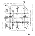
触感再現機構は、図2(A)及び図2(B)に示すように、第1磁石40a〜第4磁石40dの4つの磁石が設けられた基部42と、該基部42に対して移動可能に設けられ、かつ、中央部を基準として上下左右に配置された4つのコイルから構成された再現部44とからなる。なお、基部42は本発明の磁界発生部に相当し、再現部44は、本発明の推力発生部に相当する。
【0031】
基部42に設けられた4つの磁石40a〜40dは、互いに隣り合う磁石同士が逆に分極するように2行2列に配置されており、互いに隣り合う磁石間で磁界の向きが逆方向となるように構成されている。
【0032】
再現部44は、指載置部45、第1コイル46a〜第4コイル46dの4つのコイル、及び摺動部48から構成されている。指載置部45は、再現部44の最上層に設けられており、後述する推力を載置された指に伝達する。
【0033】
指載置部45の下層側には、4つのコイルが設けられている。これら4つのコイルはそれぞれ図3(A)、図3(B)及び図3(C)に示すように、一対の対向する辺のうち一方の辺側が2段、他方の辺側が4段となるように巻き方を変えて一方の辺側の高さを他方の辺側の高さの半分となるように巻き付けた構成のコイル46である。
【0034】
これら4つのコイル46a〜46dは、図2(A)及び図2(B)に示すように、高さの低い辺側が重なるように十字状に重ね合わせて固着され、各コイル46a〜46dの少なくとも一辺がそれぞれ基部42に設けられた磁石40a〜40dによる磁界を横切るように、摺動部48を介して基部42上に設けられている。4つのコイル46a〜46dをこのように配置しているため、重ね合わされた4つのコイル46a〜46dの厚さがほぼ均等になる。
【0035】
なお、摺動部48は、低摩擦材料より構成されており、後述する推力を再現部に伝達する。このような低摩擦材料としては、例えば、ポリテトラフルオロエチレンなどのフッ素樹脂、潤滑油を含浸した樹脂や金属、潤滑油などの流体等を用いることができる。また、摺動部48を非磁性体より成る球体や円柱等の部材より構成し、これら球体や円柱等の転がりによって指載置部を摺動させるように構成することもできる。
【0036】
各コイル46a〜46dにはそれぞれ駆動回路15から電流が供給される。各コイル46a〜46dに供給される電流は、後述する制御部10によってそれぞれ流れる向きと大きさとが調整されている。各コイル46a〜46dに電流が供給されると、図4に示すフレミングの左手の法則により各コイル46a〜46dに電流の流れる向きと大きさに応じた推力が働き、この推力が指載置部に伝達されるので、指載置部には各コイル46a〜46dに生じた推力を合成した合力が働くことになり、これが再現対象の物体の触感となる。
【0037】
ここで、磁石による磁界とコイルに供給される電流の流れる向きとについて、例えば、図2(A)及び図2(B)に示した第1磁石40aと第1コイル46aを例に挙げて説明する。ここでは、第1磁石40aは上面側がN極、下面側がS極に分極しており、基部42の垂直方向であるZ軸方向に磁界を生じさせているものとする。また、第1コイル46aは、一辺が前記磁石の上方で基部42表面と平行な面内の任意の方向であるX方向に沿って配置されるものとする。
【0038】
すなわち、基部42の垂直方向であるZ軸方向の磁界中にX軸方向に電流が通過することで、Y軸方向の推力が生じる。このため、第1コイル46aに時計回りの電流を流すと、コイルは+Y軸方向に推力を発生させる。また、電流の向きを反時計回りに変更すれば、推力が作用する方向も−Y軸方向に変更される。さらに、流す電流の値を大きくすれば、大きな推力が発生し、小さくすれば、小さな推力が発生するので、流す電流値の大きさを調節することにより発生する推力の大きさを調節することができる。
【0039】
さらに、発生できる推力の方向はX軸方向やY軸方向だけに留まらず、Z軸を中心として回転する方向に推力を発生させることも可能である。すなわち、図2において、第1コイル46aに時計回りの電流を流し、第1コイル46aと対向して配置された第3コイル46cに反時計回りの電流を流すことにより、互いに反対方向に働く推力が発生するため、結果的にZ軸を中心とする回転モーメントが指載置部45に作用することになる。なお、第2コイル46bと、第2コイル46bに対向して配置された第4コイル46dについても同様である。
【0040】
さらに、上記2つのコイルに対して流す電流の大きさが異なると反対方向に働く力のバランスも電流値に応じて変化するため、回転中心をずらすことができる。すなわち、上記2つのコイルに対して流す電流の大きさを調整することにより回転中心を変えるように調整することも可能である。
【0041】
本実施の形態では、1つの磁石に対して2つのコイルを対応させて配置し、1つの磁石に対して大きさが調節可能で直交する向きの2種類の電流を流す構成とすることにより三次元的に推力を発生させ、このような磁石とコイルを4つ組み合わせて発生させた推力を合成して三次元的な触感を再現している。
【0042】
なお、図5に、磁石とコイルに流す電流の向きの組み合わせに応じて作用する推力の方向の例を示す。図5(A)は1つの磁石41に対して2つのコイル47a、47bを対応させ、直交する2方向に電流を流した場合に推力が作用する方向を示し、図5(B)は2つの磁石41a、41bに対して3つのコイル47a、47b、47cを対応させて直交する向きに3つの電流を流した場合にそれぞれの磁石による磁界に応じて発生する推力の作用する方向を示し、図5(C)は図5(B)における2つの磁石41a、41bに対する3つのコイル47a、47b、47dの配置を変えた場合のそれぞれの磁石による磁界に応じて発生する推力の作用する方向を示している。
【0043】
また、特徴量測定装置18は、触感情報入力手段に対応しており、図6に示すように、接触子50、変位計52、及び第1の基準パッド54を備えている。接触子50は、力覚センサ56を備えており、力覚センサ56は接触子50が受ける反力を電気信号に変換して制御部10に出力する。
【0044】
接触子50は、触感を呈示する部位に応じた大きさ及び形状を備える。ここでは、人の指先に触感を提示する場合について説明する。そのため、接触子50は人の指先に類似する形状をしている。例えば、先端が半球形状で直径15mm程度の円柱状とするとよい。もちろん、接触子50は、この大きさに限定されるものではない。
【0045】
なお、本発明は手のひら、足の裏、腕など触感を感じ取れる部位であれば、どの部位にも適用することができるので、接触子50の形状も対象となる部位に対応する形状とすることができる。
【0046】
また、接触子50は、図示しない駆動機構により第1の基準パッド54上を摺動するように移動される。第1の基準パッド54は、図7(A)に示すように、断面形状が矩形状の複数の凸状部が表面に設けられたものであり、表面情報の特徴量である突状部の高さ寸法h、幅寸法w、凹凸の比率や凹凸パターン(すなわち、繰り返し周期S)が予め決定されている。なお、基準パッドはこのような形状に限定されるものではなく、既知の表面形状のものであれば、例えば、パッド表面に多数の半円球が分布された構成のパッドなどその他の構成のパッドを基準パッドとして用いることができる。
【0047】
変位計52は、接触子50が図示しない駆動機構により第1の基準パッド54上を摺動されたときに、接触子50に予め設けられたマークを検出することで、接触子の上下変動量を測定し、得られた結果を制御部10に出力する。
【0048】
ここで、第1の基準パッド54上を接触子50が摺動したときに接触子50が受ける反力情報の1成分Fxのグラフ60と接触子50の上下変動量を示すグラフ62とを図8に示す。なお、図8では、反力情報の成分を左軸に示し、右軸を接触子の上下変動量を右軸に示し、横軸は摺動し始めてからの距離(mm)を示している。また、使用した第1の基準パッド54は、ここでは、突状部の高さ寸法h=1mm、幅寸法w=4mm、凹凸の比率が0.2のものを使用している。
【0049】
ここで、図7(B)に示すように、断面形状が三角形状の複数の凸状部が連続して設けられた第2の基準パッド上を上記と同様にして接触子50を摺動させたときに接触子50が受ける反力情報の1成分Fxのグラフ61と接触子50の上下変動量を示すグラフ63とを図9に示す。なお、第2の基準パッドは、突状部の高さ寸法h=1mm、幅寸法w=4mm、凹凸の比率が0.5のものを使用している。
【0050】
図8と図9とを比較すると、表面形状が類似しているものは、検出される反力情報の1成分Fxのグラフ及び接触子50の上下変動量を示すグラフも類似したものとなり、一方に対する他方の特徴量の差が波形の差となって現れることがわかる。従って、類似した形状毎に表面形状を分類し、特徴量の変化に対応する波形変化を求めておくことで、特徴量の入力だけで所望の表面形状の触感を再現できる。
【0051】
ここで、データ生成プログラムにより制御部10が行う触感データの生成ルーチンについて図10を参照して説明する。まず、ステップ100では、ディスプレイに表示された画像のうち、選択されたものがあるかを判断する。選択された画像がある場合、次のステップ102に移行してその画像を表わす画像データに特徴量データが含まれるかを判断する。ここでは、この特徴量は、分類、触感を再現する画像データが表わす画像の表示画面内での大きさ寸法、凹凸の高さ、凹凸の比率、及び凹凸パターンを含んでいる。
【0052】
ステップ102において特徴量のデータが添付されていない場合は、触感再現対象外の画像であるので、本ルーチンを終了する。特徴量のデータが添付されている場合は、ステップ104に移行して、予め用意されている複数の基本波形のうち、選択された画像データの分類に対応する基本波形 (例えば、図11(A))を選択する。なお、ここでは、上下変動量の波形について説明するが、本発明では、例えば、反力に応じた波形などの種々の成分毎に同様な処理を行って特徴量に応じた波形を得ている。
【0053】
次のステップ106では、特徴量データに含まれる大きさ情報が表わす大きさ寸法と、選択した基本波形が表わす大きさ寸法とが異なるかを判断し、同じ場合はステップ110に移行し、異なる場合は、ステップ108に移行して特徴量データに含まれる大きさ情報に基づいて基本波形を修正して、ステップ110に移行する。例えば、図11(B)は、図11(A)に示した基本波形の1/2の寸法の波形となるように幅が縮小されている。
【0054】
ステップ110では、特徴量データに含まれる高さ情報が表わす高さ寸法と、選択した基本波形が表わす高さ寸法とが異なるかを判断し、同じ場合はステップ114に移行し、異なる場合は、ステップ112に移行して特徴量データに含まれる高さ情報に基づいて基本波形を修正して、ステップ114に移行する。例えば、図11(C)は、図11(B)に示した波形の3/2倍高さの寸法となるように波形の高さが拡大されている。
【0055】
ステップ114では、特徴量データに含まれる凹凸の比率の情報と、選択した基本波形の凹凸の比率とが異なるかを判断し、同じ場合はステップ118に移行し、異なる場合は、ステップ116に移行して特徴量データに含まれる凹凸の比率の情報に基づいて基本波形を修正して、ステップ118に移行する。例えば、図11(D)は、図11(C)に示した波形において、凹部の幅:凸部の幅=1:5となるように波形の凹凸の比率を変更している。
【0056】
次のステップ118では、特徴量データに含まれる凹凸パターンの情報があらわす凹凸パターンと、選択した基本波形の凹凸パターンが異なるかを判断し、同じ場合はステップ122に移行し、異なる場合は、ステップ120に移行して、特徴量データに含まれる凹凸パターンの情報に基づいて基本波形を修正して、ステップ122に移行する。例えば、図11(E)は、図11(D)に示した波形において、凸部パターンを修正した場合の一例である。
【0057】
ステップ122では、得られた波形を触感再現用のデータとして駆動回路15に出力して本ルーチンを終了する。
【0058】
このようにして制御部により生成された触感再現用の駆動データは駆動回路15に出力される。駆動回路15は、触感再現用のデータと同じ反力と上下変位量が指載置部に再現されるように、各コイルに流す駆動電流のそれぞれの大きさ及び電流の流れる向きとを決定して各コイルを駆動する。例えば、消費電力を抑制することが可能なPWM制御により各コイルを駆動すると良い。
【0059】
このように、本実施の形態では、画像データに添付されている特徴量に基づいて対応する分類の基本波形を修正して触感再現対象の画像の触感を再現する構成であるので、予め所望の触感毎に対応させて触感データを記憶させる必要がなく、多種多様の物体の表面をなぞったときの触感を再現することが可能である。なお、キーボードなどの入力装置から特徴量を入力する構成とすることもできる。この場合、ディスプレイの画面に表示された画像に関連付けて特徴量を記憶させることもできるので、新たな触感再現画像の作成が容易にできる。
【0060】
なお、本実施の形態では、ポインティングデバイス14のボタンに本発明の触感呈示装置を適用した場合について説明したが、本発明は、この構成に限らず、例えば、図12に示すように、ポインティングデバイス14とは別の触感呈示用デバイス19を設け、該触感呈示用デバイス19により触感を呈示するように構成することも可能である。
【0061】
また、磁界発生部として4つの磁石を設けた構成について説明したが、図13に示すように、環状の略矩形状の第1磁石40eの中に逆の極性の第2磁石40fを配置し、4つのコイル46e〜46hを第1磁石40eと第2磁石40fとの両方に跨るように配置した構成とすることもできる。
【0062】
また、触感再現機構は、4つの磁石と4つのコイルとからなる構成に限定するものではなく、図14に示すように、9つなどの多数の磁石40から磁界発生部を構成し、再現部44を複数の磁石40のそれぞれに複数のコイルが対応するよう複数のコイルを組み合わせて設けた構成としたり、図15に示すように、多数の磁石から構成された磁界発生部上を、例えば、4つのコイルからなる再現部44が移動する構成するなど、磁石40とコイル46とを用いたものであれば種々の構成に適用することができる。
【0063】
なお、本実施の形態では触感再現機構としては、磁石とコイルとを備え、電流の流れ方向と大きさを調整することにより発生する推力を調整して触感を再現する構成としたが、本発明はこの構成に限定されるものではなく、例えば、微小なピン部材を立てた状態で多数敷き詰め、該ピン部材をアクチュエータなどで倒すことによりピン部材の上端側に載置される指などの受感部に触感を伝達する構成等別の構成に適用することもできる。
【0064】
また、本実施の形態では、特徴量測定装置を一体に備え、特徴量測定装置により測定された基本波形を記憶しておき、該記憶された波形を基本発明として各種処理を行う構成としているが、特徴量測定装置を一体に備えない構成とすることも可能である。
【0065】
すなわち、外部記録装置20によりフロッピーディスクやMOなどの記録媒体から基本波形を読み込んで使用するようにすることもできる。この場合、特徴量測定装置を独立した1個の装置としてもよい。
【0066】
【発明の効果】
以上説明したように本発明によれば、多種多様の物体の表面をなぞったときの触感を再現することが可能となる、という効果が得られる。
【図面の簡単な説明】
【図1】本実施の形態のパーソナルコンピュータの概略を示すブロック図である。
【図2】図2(A)は図1に示した触感再現機構の概略構成を示す説明図であり、図2(B)は図2(A)のA−A線断面図であり、図2(C)はポインティングデバイスの断面図である。
【図3】図3(A)は図2に示した触感再現機構に用いるコイルの構成を示す上面図であり図3(B)は図3(A)のB−B線断面図であり、図3(C)は図3(A)のB−B線矢視断面図である。
【図4】垂直方向に磁界を発生させる磁石に一定方向の電流を流したときに発生する推力の方向を示す説明図である。
【図5】磁石とコイルに流す電流の向きの組み合わせに応じて作用する推力の方向の例を示す説明図である。
【図6】特徴量測定装置の概略構成を示す説明図である。
【図7】図7(A)は第1の基準パッドの表面形状を説明する斜視図であり、図7(B)は第2の基準パッドの表面形状を説明する斜視図である。
【図8】第1の基準パッド上を接触子が摺動したときに接触子が受ける反力情報の1成分Fxのグラフ、及び、接触子の上下変動量を示すグラフである。
【図9】第2の基準パッド上を接触子が摺動したときに接触子が受ける反力情報の1成分Fxのグラフ、及び、接触子の上下変動量を示すグラフである。
【図10】データ生成プログラムにより制御部が行う触感データの生成ルーチンである。
【図11】図11(A)は任意の分類の基本波形であり、図11(B)は特徴量データに含まれる大きさ情報に基づいて図11(A)の波形を修正したときの波形であり、図11(C)は特徴量データに含まれる高さ情報に基づいて図11(B)の波形を修正したときの波形であり、図11(D)は特徴量データに含まれる凹凸の比率に基づいて図11(C)の基本波形を修正したときの波形であり、図11(E)は特徴量データに含まれる凹凸パターンに基づいて図11(D)の基本波形を修正したときの波形である。
【図12】本発明の触感呈示装置の別の実施の形態を示す説明図である。
【図13】本発明の磁界発生部の別の実施の形態を示す説明図である。
【図14】本発明の触感再現機構の別の実施の形態を示す説明図である。
【図15】本発明の触感再現機構のさらに別の実施の形態を示す説明図である。
【符号の説明】
10 制御部
12 ディスプレイ
14 ポインティングデバイス
15 駆動回路
16 キーボード
18 特徴量測定装置
19 触感呈示用デバイス
20 外部記録装置
28 バス
30 触感呈示ボタン
40、41、41a、41b、40a〜40f 磁石
42 基部
44 再現部
45 指載置部
46、46a〜46h コイル
48 摺動部
50 接触子
52 変位計
54 基準パッド
56 力覚センサ[0001]
BACKGROUND OF THE INVENTION
The present invention relates to a tactile sensation presentation device, and in particular, in a so-called GUI (graphical user interface) in an information processing device, a tactile sensation felt when an object displayed on the information processing device presentation unit is touched or traced is simulated. The present invention relates to a tactile sensation presentation device.
[0002]
[Prior art]
In general, the information obtained from the tactile sensation is finally determined when the object is recognized and a specific judgment is made among the sensory information perceived using the receiving organs such as eyes, ears, nose, hands, and fingers. Often becomes the decisive factor. That is, by touching the object with a hand or a finger, the surface information of the object such as rough feeling or unevenness is understood and various judgments are made.
[0003]
By the way, with the rapid spread of information devices and communication information devices such as the Internet and game machines in recent years, information that is displayed on the screen of a display device such as a personal computer or a television and depends on visual information, such as products and exhibits. Information such as products introduced in documents such as magazines, pamphlets and catalogs is increasing.
[0004]
Information from these information devices and communication information devices is only displayed on the screen and appeals linguistically and visually. Therefore, the user can recognize the object linguistically and visually, but it is difficult to sense the atmosphere and the bodily sensation. Therefore, it is necessary for the user to guess and complement the missing part of the information based on his / her experience to understand.
[0005]
Further, as information communication devices mainly relying on visual information, such as the Internet and game machines, become more popular, user demands are increasing. Therefore, in the future, it is expected that there will be a demand for pseudo-tactile sensation when tracing an untouchable object displayed as an image on an information communication device.
[0006]
As means for obtaining a tactile sensation, for example, Japanese Patent Laid-Open Nos. 11-10561, 11-33937, and 9-155785 have been proposed.
[0007]
Japanese Patent Laid-Open No. 11-10561 has a plurality of object shape presenting means having a head having a curved surface, a flat surface, and a convex edge, and the operator selects the object shape presenting head according to the shape desired to be presented by the operator. An object shape presentation device configured to present an object shape to a fingertip has been proposed.
[0008]
Japanese Patent Application Laid-Open No. 11-33937 includes an environment presentation tool having a convex edge, a concave edge, a convex curved surface, a concave curved surface, and a plane, and the surface of the presentation tool is selected according to the shape desired by the environmental operator. Thus, a force-tactile display method for presenting an object shape has been proposed.
[0009]
Further, Japanese Patent Application Laid-Open No. 9-155785 discloses a tactile sensation that processes a signal from a detection means for detecting a contact state with an object, and finally converts it into tactile perception information that can be perceived by a person and transmits it to the user. A presentation device has been proposed.
[0010]
[Problems to be solved by the invention]
However, the object shape presenting devices disclosed in Japanese Patent Application Laid-Open Nos. 11-10561 and 11-33937 accurately present the surface shape and deformation state of the target object. Many types of object shape presentation heads or environment presentation tools corresponding to the shape must be prepared, and the apparatus becomes complicated. In addition, since the tactile sensation is reproduced by the object shape presentation head or the environment presentation tool prepared in advance, there is a problem that the types of tactile sensations that can be presented are limited.
[0011]
Further, in Japanese Patent Application Laid-Open No. 11-33937, it is necessary to install an object for which a tactile sensation is to be presented on the detection means of the tactile sense presentation device. Therefore, when presenting the tactile sensation of a remote object, the object must be set up by reaching the detection means, and there is a problem that the degree of freedom in setting is impaired.
[0012]
Further, an object shape presenting device disclosed in Japanese Patent Application Laid-Open No. 9-155785 has a voice coil based on an arbitrary waveform signal corresponding to a human perceptual characteristic in a state where a finger is placed on a button-shaped signal presenting part. There is a problem in that the tactile sensation when the surface of the target object is traced cannot be reproduced because the motor is driven to mechanically vibrate the signal presentation site and transmit it to the person.
[0013]
In view of the above, an object of the present invention is to provide a tactile sensation providing apparatus capable of reproducing the tactile sensation when tracing the surface of a wide variety of objects.
[0014]
[Means for Solving the Problems]
In order to achieve the above object, the invention according to
[0015]
The tactile sensation providing apparatus according to
[0016]
The information generation means Tactile reproduction object By correcting the reference tactile information according to the feature amount (in other words, the amount of deviation from the reference tactile information). Tactile reproduction object The tactile sensation information is generated, and the presenting means is generated by the information generating means Tactile reproduction object Based on tactile information Move the thrust generator in the horizontal direction in the direction that combines the thrust generated by multiple coils. Said by Tactile reproduction object Reproduce the tactile sensation. That is, in the tactile sensation providing apparatus according to
[0017]
In addition, as described in claim 2, the information generation unit stores reference tactile information for each of a plurality of predetermined classifications, and is selected by the selection unit. Tactile reproduction object Select the tactile information of the same classification as the classification to which the Tactile reproduction object The tactile sensation information should be generated.
[0018]
For example, there are many fine irregularities on the surface Tactile reproduction object , With a smooth surface with almost no irregularities on the surface Tactile reproduction object , Has an uneven surface with large amplitude Tactile reproduction object Such as multiple surface shapes that have large differences in tactile information Tactile reproduction object By creating standard tactile sensation information every time, it is possible to reduce the amount of calculation when generating tactile sensation information from feature amounts, so that errors included in the finally obtained tactile sensation information can be reduced. it can. Accordingly, it is possible to reproduce a tactile sensation closer to the real thing.
[0019]
In addition As a presentation means for reproducing the tactile sensation, for example, , Magnetic field generator that generates a magnetic field And a portion having a plurality of coils arranged so as to generate thrust in different directions in a horizontal plane by passing a current through the magnetic field generated by the magnetic field generator, and obtaining a tactile sensation of the user. A tactile sensation reproduction object that is composed of a thrust generation unit that is placed and is selected by the selection means by moving the thrust generation unit in a horizontal direction in a direction in which the thrusts generated by the plurality of coils are combined. The thing of the structure which reproduces and shows the tactile sense of can be used.
[0020]
Note that the number of magnetic field generation units is not limited to one, and the presenting unit is provided with a plurality of magnetic field generation units to control the flow direction and magnitude of the current supplied to each magnetic field generation unit by the control unit. be able to. By configuring in this way, more complicated load reproduction can be realized.
[0021]
The reference tactile sensation information includes the reaction force from the object received by the contacted object corresponding to the amount of movement of the contacted object when tracing an object with a known surface shape, the amount of vertical fluctuation when the object is touched, etc. The physical phenomenon is converted into electrical tactile information, for example, 3 As described in the above, it can be an electrical signal such as digital data or analog data in which the reaction force from the object corresponding to the amount of movement of the contacted object and the vertical fluctuation amount are combined.
[0022]
The feature amount is a shape change amount with respect to the object having the known surface shape, for example, 4 As described above, it can be represented by at least one of the height of the shape constituting the object surface, the object size, and the ratio of the unevenness of the object surface. Note that the feature amount may be a change amount of the driving signal of the presenting means that changes in presentation according to the shape change amount.
[0023]
Furthermore, the reference tactile sensation information may be input from the outside, and 5
[0024]
The amount of vertical displacement of the contact can be detected by a displacement amount detecting means such as a displacement meter, for example. 6 As described above, the tactile sensation information input means includes at least one of a deformed state of the contact tip, a recessed state of the reference object surface, and a contact area between the contact tip and the reference object surface. The vertical displacement amount may be calculated from the above.
[0025]
DETAILED DESCRIPTION OF THE INVENTION
Hereinafter, embodiments of the present invention will be described in detail with reference to the drawings. In this embodiment, a tactile sensation providing apparatus is applied to a personal computer.
[0026]
First, as shown in FIG. 1, the personal computer according to the present embodiment is roughly divided into a
[0027]
The
[0028]
The
[0029]
As shown in FIG. 2C, the
[0030]
As shown in FIGS. 2A and 2B, the tactile sensation reproduction mechanism is movable with respect to the base 42 provided with four magnets of the
[0031]
The four
[0032]
The
[0033]
Four coils are provided on the lower layer side of the
[0034]
As shown in FIGS. 2A and 2B, these four
[0035]
In addition, the sliding part 48 is comprised from the low friction material, and transmits the thrust mentioned later to a reproduction part. As such a low friction material, for example, a fluororesin such as polytetrafluoroethylene, a resin impregnated with a lubricating oil, a metal, a fluid such as a lubricating oil, or the like can be used. Moreover, the sliding part 48 can be comprised from members, such as a spherical body and a cylinder which consist of a nonmagnetic body, and it can also comprise so that a finger mounting part may be slid by rolling, such as these spherical bodies and a cylinder.
[0036]
A current is supplied from the
[0037]
Here, the magnetic field by the magnet and the direction in which the current supplied to the coil flows will be described by taking, for example, the
[0038]
That is, a current in the X-axis direction passes through a magnetic field in the Z-axis direction, which is the vertical direction of the
[0039]
Furthermore, the direction of the thrust that can be generated is not limited to the X-axis direction and the Y-axis direction, and it is also possible to generate the thrust in a direction that rotates about the Z-axis. That is, in FIG. 2, a clockwise current is passed through the
[0040]
Furthermore, if the magnitudes of currents flowing through the two coils are different, the balance of forces acting in opposite directions also changes according to the current value, so that the center of rotation can be shifted. That is, it is possible to adjust the rotation center by changing the magnitude of the current passed through the two coils.
[0041]
In the present embodiment, two coils are arranged in correspondence with one magnet, and the configuration is such that two types of currents that can be adjusted in size and orthogonal to each other are supplied to one magnet. A three-dimensional tactile sensation is reproduced by originally generating a thrust and synthesizing the thrust generated by combining four such magnets and coils.
[0042]
FIG. 5 shows an example of the direction of thrust acting according to the combination of directions of currents flowing through the magnet and the coil. FIG. 5A shows the direction in which thrust acts when two
[0043]
The feature
[0044]
The
[0045]
In addition, since this invention can be applied to any part as long as it can feel a touch feeling such as a palm, the sole of a foot, and an arm, the shape of the
[0046]
Further, the
[0047]
The
[0048]
Here, a
[0049]
Here, as shown in FIG. 7B, the
[0050]
8 and 9, when the surface shape is similar, the graph of the one-component Fx of the detected reaction force information and the graph showing the vertical fluctuation amount of the
[0051]
Here, a tactile sensation data generation routine performed by the
[0052]
If no feature amount data is attached in
[0053]
In the
[0054]
In
[0055]
In
[0056]
In the
[0057]
In
[0058]
The tactile sensation driving data generated by the control unit in this way is output to the driving
[0059]
As described above, in the present embodiment, the basic waveform of the corresponding classification is corrected based on the feature amount attached to the image data, and the tactile sensation of the image to be reproduced is reproduced in advance. It is not necessary to store tactile data corresponding to each tactile sensation, and it is possible to reproduce the tactile sensation when tracing the surface of various objects. In addition, it can also be set as the structure which inputs feature-value from input devices, such as a keyboard. In this case, since the feature amount can be stored in association with the image displayed on the display screen, a new tactile sensation reproduction image can be easily created.
[0060]
In the present embodiment, the case where the tactile sensation providing apparatus of the present invention is applied to the button of the
[0061]
Moreover, although the structure which provided four magnets as a magnetic field generation | occurrence | production part was demonstrated, as shown in FIG. 13, the
[0062]
In addition, the tactile sensation reproduction mechanism is not limited to a configuration composed of four magnets and four coils. As shown in FIG. 14, a magnetic field generation unit is composed of a large number of
[0063]
In the present embodiment, the tactile sensation reproduction mechanism includes a magnet and a coil, and is configured to reproduce the tactile sensation by adjusting the thrust generated by adjusting the current flow direction and magnitude. Is not limited to this configuration, for example, a large number of minute pin members are laid up, and a finger or the like placed on the upper end side of the pin member is perceived by tilting the pin member with an actuator or the like. The present invention can also be applied to other configurations such as a configuration for transmitting a tactile sensation to the part.
[0064]
In the present embodiment, the feature amount measuring device is integrally provided, the basic waveform measured by the feature amount measuring device is stored, and various processes are performed using the stored waveform as a basic invention. It is also possible to adopt a configuration in which the feature quantity measuring device is not provided integrally.
[0065]
In other words, the basic waveform can be read from a recording medium such as a floppy disk or MO by the
[0066]
【The invention's effect】
As described above, according to the present invention, it is possible to reproduce the tactile sensation when tracing the surface of a wide variety of objects.
[Brief description of the drawings]
FIG. 1 is a block diagram showing an outline of a personal computer according to an embodiment.
2A is an explanatory diagram showing a schematic configuration of the tactile sensation reproduction mechanism shown in FIG. 1, and FIG. 2B is a cross-sectional view taken along the line AA in FIG. 2C is a cross-sectional view of the pointing device.
3A is a top view showing a configuration of a coil used in the tactile sensation reproduction mechanism shown in FIG. 2, and FIG. 3B is a cross-sectional view taken along line BB in FIG. 3A. FIG. 3C is a cross-sectional view taken along the line BB in FIG.
FIG. 4 is an explanatory diagram showing the direction of thrust generated when a current in a fixed direction is passed through a magnet that generates a magnetic field in the vertical direction.
FIG. 5 is an explanatory diagram showing an example of the direction of thrust acting according to a combination of directions of currents flowing through a magnet and a coil.
FIG. 6 is an explanatory diagram showing a schematic configuration of a feature amount measuring apparatus.
FIG. 7A is a perspective view for explaining the surface shape of the first reference pad, and FIG. 7B is a perspective view for explaining the surface shape of the second reference pad.
FIG. 8 is a graph of one component Fx of reaction force information received by the contact when the contact slides on the first reference pad, and a graph showing the vertical fluctuation amount of the contact.
FIG. 9 is a graph of one component Fx of reaction force information received by a contact when the contact slides on a second reference pad, and a graph showing the amount of vertical fluctuation of the contact.
FIG. 10 is a tactile sensation data generation routine performed by the control unit according to the data generation program.
11A is a basic waveform of an arbitrary classification, and FIG. 11B is a waveform when the waveform of FIG. 11A is corrected based on size information included in feature data. FIG. 11C shows a waveform when the waveform of FIG. 11B is corrected based on the height information included in the feature amount data, and FIG. 11D shows the unevenness included in the feature amount data. 11C is a waveform when the basic waveform of FIG. 11C is corrected based on the ratio of the above, and FIG. 11E is a waveform obtained by correcting the basic waveform of FIG. 11D based on the concavo-convex pattern included in the feature amount data. It is a waveform when.
FIG. 12 is an explanatory view showing another embodiment of the tactile sensation providing apparatus of the present invention.
FIG. 13 is an explanatory diagram showing another embodiment of the magnetic field generator of the present invention.
FIG. 14 is an explanatory view showing another embodiment of the tactile sensation reproduction mechanism of the present invention.
FIG. 15 is an explanatory view showing still another embodiment of the tactile sensation reproduction mechanism of the present invention.
[Explanation of symbols]
10 Control unit
12 display
14 pointing devices
15 Drive circuit
16 keyboard
18 Feature measuring device
19 Tactile display device
20 External recording device
28 Bus
30 Tactile presentation button
40, 41, 41a, 41b, 40a-40f Magnet
42 Base
44 Reproduction part
45 Finger rest
46, 46a-46h Coil
48 Sliding part
50 contacts
52 Displacement meter
54 Reference Pad
56 Force sensor
Claims (6)
前記表示手段に表示された触感再現対象物を選択する選択手段と、
前記選択手段により選択された触感再現対象物の特徴量に基づいて、予め記憶された基準の触感情報を修正して該触感再現対象物の触感情報を生成する情報生成手段と、
磁界を発生させる磁界発生部、及び電流を通過させることにより、前記磁界発生部により発生された磁界によって水平面内の各々異なる方向に推力を発生させるように配置された複数のコイルを備え、使用者の触感を得られる部位が載置される推力発生部から構成され、前記複数のコイルにより発生した推力を合成した方向に前記推力発生部を水平方向に移動させて前記選択手段により選択された触感再現対象物の触感を再現して呈示する呈示手段と、
前記情報生成手段が生成した触感情報に基づいて、前記コイル毎に、供給する電流の流れ方向及び大きさを制御して、前記コイル毎の推力を調整する制御手段と、
を備えた触感呈示装置。Display means for displaying a tactile sensation reproduction object that reproduces the tactile sensation when touched;
Selecting means for selecting a tactile sensation reproduction object displayed on the display means;
Information generating means for correcting the tactile sensation information of the tactile sensation reproduction object by correcting the reference tactile sensation information stored in advance based on the feature amount of the tactile sensation reproduction object selected by the selection means;
A magnetic field generating unit for generating a magnetic field, and a plurality of coils arranged to generate thrust in different directions in a horizontal plane by passing a current through the magnetic field generated by the magnetic field generating unit. A tactile sensation selected by the selection means by moving the thrust generation unit in a horizontal direction in a direction in which the thrusts generated by the plurality of coils are combined is configured. Presenting means for reproducing and presenting the tactile sensation of the object to be reproduced;
Control means for adjusting the thrust direction for each coil by controlling the flow direction and magnitude of the current to be supplied for each coil based on the tactile information generated by the information generating means;
A tactile sensation presentation device comprising:
Priority Applications (1)
| Application Number | Priority Date | Filing Date | Title |
|---|---|---|---|
| JP2000119614A JP3937684B2 (en) | 2000-04-20 | 2000-04-20 | Tactile presentation device |
Applications Claiming Priority (1)
| Application Number | Priority Date | Filing Date | Title |
|---|---|---|---|
| JP2000119614A JP3937684B2 (en) | 2000-04-20 | 2000-04-20 | Tactile presentation device |
Publications (2)
| Publication Number | Publication Date |
|---|---|
| JP2001306200A JP2001306200A (en) | 2001-11-02 |
| JP3937684B2 true JP3937684B2 (en) | 2007-06-27 |
Family
ID=18630562
Family Applications (1)
| Application Number | Title | Priority Date | Filing Date |
|---|---|---|---|
| JP2000119614A Expired - Fee Related JP3937684B2 (en) | 2000-04-20 | 2000-04-20 | Tactile presentation device |
Country Status (1)
| Country | Link |
|---|---|
| JP (1) | JP3937684B2 (en) |
Families Citing this family (5)
| Publication number | Priority date | Publication date | Assignee | Title |
|---|---|---|---|---|
| JP4568310B2 (en) * | 2007-08-29 | 2010-10-27 | 株式会社日立製作所 | Display device with touch panel |
| JP4778591B2 (en) | 2009-05-21 | 2011-09-21 | パナソニック株式会社 | Tactile treatment device |
| JP4769342B2 (en) * | 2009-09-03 | 2011-09-07 | パナソニック株式会社 | Tactile sensation reproduction method, apparatus, computer program, and recording medium recording the computer program |
| JP2013028152A (en) * | 2011-06-24 | 2013-02-07 | Nissan Motor Co Ltd | Surface structure for article |
| JP5910100B2 (en) * | 2012-01-18 | 2016-04-27 | セイコーエプソン株式会社 | Haptic display device |
-
2000
- 2000-04-20 JP JP2000119614A patent/JP3937684B2/en not_active Expired - Fee Related
Also Published As
| Publication number | Publication date |
|---|---|
| JP2001306200A (en) | 2001-11-02 |
Similar Documents
| Publication | Publication Date | Title |
|---|---|---|
| JP3543695B2 (en) | Driving force generator | |
| JP7265567B2 (en) | Finger-worn device using sensor and tactile sense | |
| US6803924B1 (en) | Flexible variation of haptic interface resolution | |
| US9983676B2 (en) | Simulation of tangible user interface interactions and gestures using array of haptic cells | |
| Emgin et al. | Haptable: An interactive tabletop providing online haptic feedback for touch gestures | |
| KR100682901B1 (en) | Apparatus and method for providing a fingertip haptic of image information using an electroactive polymer in an image display device | |
| CA2276322C (en) | Mouse-like input/output device with display screen and method for its use | |
| US8350843B2 (en) | Virtual hand: a new 3-D haptic interface and system for virtual environments | |
| US6618037B2 (en) | Pointing device and information processing apparatus | |
| KR20150060575A (en) | Systems and methods for generating friction and vibrotactile effects | |
| JPH11203040A (en) | Touch sense display | |
| KR20090082714A (en) | Display device and method for sensing input point using magnetic fluid | |
| JP2006163206A (en) | Tactile presentation device | |
| JP2017182495A (en) | Information processing apparatus, information processing method, and program | |
| CN113311946A (en) | Multi-mode fingerstall type device for mobile terminal application | |
| JP3937684B2 (en) | Tactile presentation device | |
| JP2009163484A (en) | Rolling input device and finger motion detection program | |
| Lévesque et al. | Tactile graphics rendering using three laterotactile drawing primitives | |
| CA2457956C (en) | Haptic interface | |
| JP4168752B2 (en) | Information sensing device, information transmission system, and storage medium storing program for controlling information sensing device | |
| JP4244784B2 (en) | Driving force generator | |
| Wang et al. | Virtueledent: A compact xr tooth-cutting training system using a physical emr-based dental handpiece and teeth model | |
| JP3855561B2 (en) | Tactile force sense presentation device and information input / output device | |
| Mun et al. | Diversifying grain-based compliance illusion by varying base compliance | |
| JPH11203020A (en) | Touch sense display device |
Legal Events
| Date | Code | Title | Description |
|---|---|---|---|
| A621 | Written request for application examination |
Free format text: JAPANESE INTERMEDIATE CODE: A621 Effective date: 20040120 |
|
| A977 | Report on retrieval |
Free format text: JAPANESE INTERMEDIATE CODE: A971007 Effective date: 20060727 |
|
| A131 | Notification of reasons for refusal |
Free format text: JAPANESE INTERMEDIATE CODE: A131 Effective date: 20060801 |
|
| A521 | Written amendment |
Free format text: JAPANESE INTERMEDIATE CODE: A523 Effective date: 20060928 |
|
| TRDD | Decision of grant or rejection written | ||
| A01 | Written decision to grant a patent or to grant a registration (utility model) |
Free format text: JAPANESE INTERMEDIATE CODE: A01 Effective date: 20070306 |
|
| A61 | First payment of annual fees (during grant procedure) |
Free format text: JAPANESE INTERMEDIATE CODE: A61 Effective date: 20070319 |
|
| R150 | Certificate of patent or registration of utility model |
Free format text: JAPANESE INTERMEDIATE CODE: R150 |
|
| FPAY | Renewal fee payment (event date is renewal date of database) |
Free format text: PAYMENT UNTIL: 20110406 Year of fee payment: 4 |
|
| FPAY | Renewal fee payment (event date is renewal date of database) |
Free format text: PAYMENT UNTIL: 20120406 Year of fee payment: 5 |
|
| FPAY | Renewal fee payment (event date is renewal date of database) |
Free format text: PAYMENT UNTIL: 20130406 Year of fee payment: 6 |
|
| FPAY | Renewal fee payment (event date is renewal date of database) |
Free format text: PAYMENT UNTIL: 20130406 Year of fee payment: 6 |
|
| FPAY | Renewal fee payment (event date is renewal date of database) |
Free format text: PAYMENT UNTIL: 20140406 Year of fee payment: 7 |
|
| LAPS | Cancellation because of no payment of annual fees |