JP3935465B2 - Power supply and signal line take-out device in office space - Google Patents
Power supply and signal line take-out device in office space Download PDFInfo
- Publication number
- JP3935465B2 JP3935465B2 JP2003391981A JP2003391981A JP3935465B2 JP 3935465 B2 JP3935465 B2 JP 3935465B2 JP 2003391981 A JP2003391981 A JP 2003391981A JP 2003391981 A JP2003391981 A JP 2003391981A JP 3935465 B2 JP3935465 B2 JP 3935465B2
- Authority
- JP
- Japan
- Prior art keywords
- columnar body
- horizontal
- groove
- signal line
- power supply
- Prior art date
- Legal status (The legal status is an assumption and is not a legal conclusion. Google has not performed a legal analysis and makes no representation as to the accuracy of the status listed.)
- Expired - Fee Related
Links
- 238000000605 extraction Methods 0.000 claims description 59
- 230000000087 stabilizing effect Effects 0.000 claims description 8
- 238000005192 partition Methods 0.000 description 19
- 230000002093 peripheral effect Effects 0.000 description 19
- 230000008859 change Effects 0.000 description 4
- 210000000078 claw Anatomy 0.000 description 4
- 230000008878 coupling Effects 0.000 description 4
- 238000010168 coupling process Methods 0.000 description 4
- 238000005859 coupling reaction Methods 0.000 description 4
- 239000003381 stabilizer Substances 0.000 description 4
- 230000007246 mechanism Effects 0.000 description 3
- 230000008520 organization Effects 0.000 description 3
- 125000006850 spacer group Chemical group 0.000 description 3
- 230000000694 effects Effects 0.000 description 2
- 239000011521 glass Substances 0.000 description 2
- 238000003780 insertion Methods 0.000 description 2
- 230000037431 insertion Effects 0.000 description 2
- 229920005989 resin Polymers 0.000 description 2
- 239000011347 resin Substances 0.000 description 2
- 238000005452 bending Methods 0.000 description 1
- 239000000470 constituent Substances 0.000 description 1
- 230000008602 contraction Effects 0.000 description 1
- 230000003028 elevating effect Effects 0.000 description 1
- 238000009434 installation Methods 0.000 description 1
- 239000002184 metal Substances 0.000 description 1
- 230000006855 networking Effects 0.000 description 1
- 230000008707 rearrangement Effects 0.000 description 1
- 230000000630 rising effect Effects 0.000 description 1
- 230000006641 stabilisation Effects 0.000 description 1
- 238000011105 stabilization Methods 0.000 description 1
- 229920003002 synthetic resin Polymers 0.000 description 1
- 239000000057 synthetic resin Substances 0.000 description 1
Images


Landscapes
- Installation Of Indoor Wiring (AREA)
- Tables And Desks Characterized By Structural Shape (AREA)
- Details Of Indoor Wiring (AREA)
Description
本発明は、オフィス空間内において使用場所を変えて使用されるコンピュータ,ワードプロセッサ,電話,ファクシミリ,照明等の電子,電気機器(以下、これらをOA機器という)の電源ライン及び信号ライン、又は、いずれか一方のライン(以下、これを電源,信号ラインという)を、オフィス空間内に任意の場所に配置されるデスクの上であっても自由自在に離接することができるようにしたオフィス用のOA機器の電源,信号ラインの取出システムに関する。 The present invention relates to power lines and signal lines of electronic and electrical equipment (hereinafter referred to as OA equipment) such as computers, word processors, telephones, facsimiles, lighting, etc. that are used at different locations in the office space. One of the lines (hereinafter referred to as the power supply and signal line) can be freely connected / disconnected even on a desk placed at any location in the office space. It relates to equipment power supply and signal line extraction systems.
従来、オフィス空間内に配置されるデスク等のオフィス設備は、例えば、会社組織の中の部課制を単位として、部屋単位、或は、間仕切等で仕切った業務空間を形成し、各業務空間単位でデスクやキャビネット等の必要なオフィス家具を、ほぼ固定的に配置して形成されていた。 Conventionally, office equipment such as desks arranged in an office space, for example, forms a business space partitioned by room units or partitions, etc., with a divisional system in a company organization as a unit. The necessary office furniture such as desks and cabinets were almost fixedly arranged.
一方、最近のオフィスでは、コンピュータの導入により、いわゆる情報化が進み、オフィスワーカーの作業形態,オフィス空間も含めた作業環境,オフィス家具そのものについても大きな変化に見舞われている。
即ち、オフィスワークにとってパーソナルコンピュータは、その様々な機能、例えば、文書作成,計算,通信、それらのネットワーク化によるコミュニケーション等の多様な機能により、今やオフィス業務にはなくてはならないものになっており、一人一台は必要となってきている。そして、これらに対応すべく、コンピュータやその他のOA機器を置くためのデスク等の家具は、コンピュータ等のOA機器の電源配線や情報配線のためのケーブルを収納するため配線ダクトを設けたり、コンピュータ等のOA機器を載置するために天板を大形化して益々大型化,複雑化している。
On the other hand, with the introduction of computers in recent offices, so-called computerization has progressed, and the working style of office workers, the working environment including the office space, and the office furniture itself are also undergoing major changes.
In other words, personal computers are now indispensable for office work due to various functions such as document creation, calculation, communication, and communication by networking them for office work. , One by one is becoming necessary. In order to cope with these, furniture such as desks for placing computers and other OA equipment is provided with wiring ducts for storing cables for power supply wiring and information wiring of OA equipment such as computers. In order to mount OA equipment such as, top plates have become larger and larger and more complicated.
しかしながら、上記のようにコンピュータの機能が向上し、オフィスへの導入が進んだ結果、オフィスのワーク形態にも大きな変化が起きており、今後それがますます大きくなることが予想される。
即ち、まず、コンピュータにより、様々な諸雑務が合理化されることによって、より生産性が高く質も高い知的ワークが求められよう。また、その場で対面していなくともコンピュータ等を通したコミュニケーションが円滑に行われる結果、従来の縦割りの組織が必要なくなり、より効率的な業務形態をとることが可能なフラットな組織、そして、臨機応変に目的を達成するためのプロジェクトチームなどによるワークスタイル等が増えてくると思われる。
これらの様々なワークスタイルは、ワークの内容に応じた最適のオフィス環境が望まれるわけであり、しかもその環境は常に様々な変化に対応できる自由さ、即ち、フレキシビリティをもっていることが必要となる。
しかしながら、これまでのオフィス家具は、上述したようにデスクや間仕切等の家具自体に配線機能を取り込み、これらを固定的に配置する使用形態であったために、今後予想される使用中のコンピュータ等のOA機器とそれを載置した家具の移動を伴うフレキシブルなオフィス環境の設定やワーク形態の実現には全くといってよい程対応できないのが現状である。
However, as described above, the computer functions have improved and the introduction into the office has progressed. As a result, there has been a major change in the work form of the office, and it is expected that this will increase in the future.
That is, first, various kinds of miscellaneous tasks will be rationalized by a computer, so that intelligent work with higher productivity and higher quality will be required. In addition, as a result of smooth communication through computers, etc. even if they are not face-to-face, there is no need for a conventional vertically divided organization, and a flat organization that can take a more efficient business form, and It seems that work styles by project teams, etc. to achieve the purpose in a flexible manner will increase.
For these various work styles, an optimal office environment according to the content of the work is desired, and the environment must always have the freedom to cope with various changes, that is, flexibility. .
However, since office furniture so far was a form of use in which the wiring function is taken into the furniture itself such as a desk and a partition as described above and these are fixedly arranged, such as a computer in use that is expected in the future. At present, it is not possible to cope with the setting of a flexible office environment and the realization of a work form accompanied by movement of OA equipment and furniture on which it is placed.
即ち、オフィス空間内で、人事異動や配置替えなどにより、デスクを移動させるには、そのデスク内の配線ダクトに取込まれている床や壁等からの電源,信号ラインを一旦切り離し、そのデスクの移動先で再接続しなければならず、また、OA機器類だけを移動させる場合、移動先に電源,信号ラインのコンセント等のコネクタがなければ、新ためてその電源,信号ラインを手配する必要があるからである。 In other words, in order to move a desk in the office space due to personnel changes or rearrangement, the power and signal lines from the floor and walls taken into the wiring duct in the desk are temporarily disconnected and the desk's It is necessary to reconnect at the destination, and when moving only OA equipment, if there is no connector such as a power source or signal line outlet at the destination, it is necessary to prepare a new power source and signal line. Because there is.
しかし、上記のようにワーク形態の変更等に応じてオフィス空間内で自由に移動できるように形成されたデスクやキャビネットに対し、その上で使用するOA機器類の電源,信号ラインの接続形態をどのようにするかは、未だ解決されていない。 However, for the desks and cabinets that can be moved freely in the office space according to the change of the work form as described above, the power supply and signal line connection form of the OA equipment used on it How to do it has not been solved yet.
本発明は以上のような点に鑑み、オフィス空間内でデスク等の家具を自由に移動,配置しても、その移動先で使用するOA機器類の電源,信号ラインを容易かつ迅速に離,接することができる一方、そこで使用するデスク等のオフィス家具には従来品のような配線ダクトや配線取出口を一切不要にできるオフィス用の電源,信号ラインの取出し装置を提供することを課題とするものである。 In view of the above points, the present invention easily and quickly separates the power and signal lines of OA equipment used at the destination even if furniture such as a desk is freely moved and arranged in the office space. It is an object of the present invention to provide an office power supply and a signal line take-out device that can eliminate the need for wiring ducts and wiring outlets as in conventional products in office furniture such as desks that can be used there. Is.
上記課題を解決することを目的としてなされた本発明の構成は、オフィス内の床に位置可変に立設される柱状体と電源ケーブルと信号ケーブルを収納できるように形成された横杆体を組合せて自立型の配線ダクトに形成したオフィス空間における電源,信号ラインの取出装置において、前記横杆体の長さ方向の略全長に亘り横杆体の上位に二重壁が形成する隙間状の溝を設けると共に該溝の任意の位置に天板支持ブラケットを設け、該ブラケットを介して天板を前記横杆体の上方に設けたことを特徴とするものである。 The structure of the present invention, which has been made for the purpose of solving the above-mentioned problems, is a combination of a columnar body erected on a floor in an office, a horizontal cable body formed so as to accommodate a power cable and a signal cable. In a power supply and signal line take-out device in an office space formed in a self-supporting wiring duct, a gap-like groove formed by a double wall is provided on the upper side of the horizontal frame over substantially the entire length of the horizontal frame. A top plate support bracket is provided at an arbitrary position of the groove, and the top plate is provided above the horizontal casing via the bracket.
本発明において、前記横杆体は、電源ケーブルとコネクタ、信号ケーブルとコネクタを収納できる溝部を具備するか、又は、溝状部材により形成したものであり、また、少なくとも左右の柱状体とケーブルを収納できる横杆体は、接続部材を介して略門型に組合せて自立型の配線ダクトに形成し、前記横杆体を床面に平行に配設した構成とする。 In the present invention, the horizontal housing includes a groove portion that can store a power cable and a connector, a signal cable and a connector, or is formed by a groove-shaped member, and stores at least the left and right columnar bodies and the cable. The horizontal body that can be formed is formed into a self-standing wiring duct by being combined in a substantially gate shape via a connecting member, and the horizontal body is arranged parallel to the floor surface.
上記において、柱状体と横杆体の組合せにより形成される配線ダクトは、前記横杆体を連接するとき、中間の柱状体を共用して形成にすることができる。 In the above, the wiring duct formed by the combination of the columnar body and the horizontal frame can be formed by sharing the intermediate columnar body when connecting the horizontal frame.
更に、上記横杆体にはその上方又は下方にスクリーンやパネルを二重壁が形成する隙間状の溝に係止させて設けた構成とすることもできる。 Further, the horizontal frame may be configured such that a screen or a panel is engaged with a gap-like groove formed by a double wall above or below the horizontal frame.
また、前記柱状体はその下部に安定部材を設けたものを使用することがある。 Also, the columnar body may be used which is provided with stabilizing members thereunder.
本発明では、柱状体と横杆体を組合せて形成した配線ダクトによる電源,信号ラインの取出装置は、前記横杆体に沿って位置又は配向を任意に選択してデスク又はテーブルを当接又は近接させて配置できるように形成される。 In the present invention, the power supply and signal line take-out device by the wiring duct formed by combining the columnar body and the horizontal frame is arbitrarily selected in position or orientation along the horizontal frame to bring the desk or table into contact with or close to each other. It is formed so that it can be arranged.
オフィス内の床に位置可変に立設される柱状体と電源ケーブルと信号ケーブルを収納できるように形成された横杆体を組合せて自立型の配線ダクトに形成したオフィス空間における電源,信号ラインの取出装置において、前記横杆体の長さ方向の略全長に亘り横杆体の上位に二重壁が形成する隙間状の溝を設けると共に該溝の任意の位置に天板支持ブラケットを設け、該ブラケットを介して天板を前記横杆体の上方に設けたので、例えば天板の高さを自由に設定できるように形成した天板の大きさが種々異なるデスク等を選択し、かつ、選択したデスク等を自由な配向で任意の位置に移動させて配置することにより、種々のワーク形態に対応するためのワークブースを、任意かつ容易に形成することができる。 Extraction of power and signal lines in office space formed in a self-supporting wiring duct by combining a columnar body erected on the floor in the office and a horizontal casing formed so as to be able to store a power cable and a signal cable In the apparatus, a gap-like groove formed by a double wall is provided on the upper side of the horizontal frame over substantially the entire length of the horizontal frame, and a top plate support bracket is provided at an arbitrary position of the groove. Since the top plate is provided above the horizontal housing, for example, a desk or the like having a different size of the top plate formed so that the height of the top plate can be freely set is selected, and the selected desk or the like By moving to an arbitrary position in a free orientation, a work booth for accommodating various work forms can be arbitrarily and easily formed.
次に、本発明の実施の形態について図に拠り説明する。図1〜図4は、全体として大略ポール状をなす電源,信号ラインの取出ポイントを形成する柱状体の例をそれぞれ示した斜視図、図5は図1〜図4に使用した柱状体の平断面図、図6は図1〜図4に例示した柱状体と図7に断面を示した横杆体の組合せにより形成した本発明電源,信号ライン取出装置の一例を示す斜視図、図7は図6の横杆体の側断面図、図8は柱状体と横杆体の接続構造の一例を示す側面図、図9はジョイントカバーの側面図、図10と図11はジョイント部材の形態例を示す斜視図、図12は本発明電源,信号ラインの取出装置の別例の正面図、図13は図12の平面図、図14は図12の左側面図、図15は図1〜図5で説明した柱状体と図7の横杆体により平面矩形状のワークブースの枠状体に形成した電源,信号ラインの取出装置の別例の斜視図、図16は本発明装置における柱状体の別例の平断面図、図17は本発明装置における横杆体の別例の側断面図、図18は図16の柱状体と図17の横杆体の結合形態の一例を説明するための斜視図、図19は柱状体と横杆体の他の例の結合形態を示す斜視図、図20は図16の柱状体と図17の横杆体とを組合せて形成した本発明取出装値の他の形態を例示した斜視図、図21は本発明電源,信号ラインの取出装置の別の形態例を示した斜視図、図22は図17の横杆体における溝状部材の側面を開閉自在の蓋構造にした例の断面図、図23は横杆体の2つの溝状部材を入れ子式構造とした例の断面図、図24は図18に示した本発明取出装置に、余長コード収納用のコードリールとシート状覆板を配備した例の斜視図、図25は図24のコードリールの取付態様の一例の要部を示す平断面図、図26は柱状体と横杆体の結合において、横杆体の平面配向角を任意の角度に設定できる構造の一例を示す斜視図、図27は図16の柱状体の安定板にキャスタを設け、当該柱状体を移動,定置可能に構成した例の斜視図、図28は図18に示した本発明装置における横杆体を伸縮自在の構造にした例の斜視図、図29は本発明電源,信号ラインの取出装置に対して使用するデスクの一例の正面図、図30は図29の左側面図、図31は図29のデスクの天板の傾斜状態を示す側面図、図32は図30のデスクの別例の正面図、図33は図32のデスクに使用する天板の別例の平面図、図34は天板の他の例の平面図、図35はデスクの他の例の正面図、図36は図35のデスクの右側面図、図37は図35のデスクの平面図、図38は取出ラインに対するデスク等の配置例を示す斜視図、図39は取出ポイントに対するデスク等の配置例を示す斜視図、図40はワークブースの枠状体に形成した取出ラインに対するデスク等の配置例を示す斜視図、図41は横杆体を間仕切パネルの笠木部分に設けた斜視図、図42は横杆体を間仕切パネルの笠木部材又は上部梁を兼用するように形成した例の斜視図、図43はパネルと収納ボックスの横杆体への取付構造の一例を示す部分断面図、図44は天板の横杆体への取付構造の一例を示す部分断面図、図45は本発明装置を利用してオフィスでの業務形態の変化例を示した平面図である。 Next, embodiments of the present invention will be described with reference to the drawings. 1 to 4 are perspective views showing examples of columnar bodies that form a power supply point and a signal line extraction point that are generally pole-shaped as a whole, and FIG. 5 is a plan view of the columnar body used in FIGS. FIG. 6 is a perspective view showing an example of the power source and signal line take-out device of the present invention formed by a combination of the columnar body exemplified in FIGS. 1 to 4 and the horizontal casing shown in FIG. FIG. 8 is a side view showing an example of a connection structure between a columnar body and a horizontal housing, FIG. 9 is a side view of a joint cover, and FIGS. 10 and 11 are perspective views showing examples of joint members. FIG. 12, FIG. 12 is a front view of another example of the power source and signal line take-out device of the present invention, FIG. 13 is a plan view of FIG. 12, FIG. 14 is a left side view of FIG. Another example of power supply and signal line take-out device formed on the frame of a rectangular work booth by the columnar body and the horizontal frame shown in FIG. FIG. 16 is a plan sectional view of another example of the columnar body in the apparatus of the present invention, FIG. 17 is a side sectional view of another example of the horizontal body in the apparatus of the present invention, and FIG. 18 is the columnar body of FIG. FIG. 19 is a perspective view illustrating another example of the coupling form of the columnar body and the horizontal frame, and FIG. 20 is a perspective view illustrating the columnar body of FIG. 16 and the horizontal frame of FIG. FIG. 21 is a perspective view showing another embodiment of the power supply and signal line take-out device of the present invention, and FIG. 22 is a side view of FIG. FIG. 23 is a cross-sectional view of an example in which the side surface of the groove-shaped member in the housing has a lid structure that can be freely opened and closed, FIG. 23 is a cross-sectional view of an example in which the two groove-shaped members of the horizontal housing have a nested structure, and FIG. FIG. 25 is a perspective view of an example in which a cord reel for storing extra length cords and a sheet-like cover plate are provided in the take-out device of the present invention, and FIG. FIG. 26 is a perspective view showing an example of a structure in which the plane orientation angle of the horizontal rod body can be set to an arbitrary angle in the connection between the columnar body and the horizontal rod body, and FIG. 27 is a stabilization plate of the columnar body of FIG. 28 is a perspective view of an example in which casters are provided and the columnar body is configured to be movable and stationary. FIG. 28 is a perspective view of an example in which the horizontal body in the device of the present invention shown in FIG. Invention Front view of an example of desk used for power supply and signal line take-out device, FIG. 30 is a left side view of FIG. 29, FIG. 31 is a side view showing an inclined state of the top plate of the desk of FIG. 30 is a front view of another example of the desk of FIG. 30, FIG. 33 is a plan view of another example of the top plate used in the desk of FIG. 32, FIG. 34 is a plan view of another example of the top plate, and FIG. FIG. 36 is a right side view of the desk of FIG. 35, FIG. 37 is a plan view of the desk of FIG. 35, and FIG. 38 is a perspective view showing an arrangement example of the desk and the like with respect to the take-out line. 39 is a perspective view showing an example of the arrangement of desks and the like with respect to the take-out point, FIG. 40 is a perspective view showing an example of arrangement of desks and the like with respect to the take-out line formed on the frame of the work booth, and FIG. FIG. 42 is a perspective view of an example in which the horizontal frame is formed so as to be used as the headboard member or the upper beam of the partition panel, and FIG. 43 is an example of a structure for attaching the panel and the storage box to the horizontal frame. 44 is a partial cross-sectional view showing an example of a structure for attaching the top board to the horizontal frame, and FIG. 45 is a plan view showing an example of a change in the business form in the office using the apparatus of the present invention. .
図1〜図5に於て、1は、図5に例示した平断面形状を有するポール状の柱状体で、図1〜図4はこの柱状体1を主体にしてオフィスの床に配設した電源ケーブルと信号ケーブルの夫々に接続されるケーブルを収装し、収装した夫々のケーブルに接続されてこの柱状体に配設した電源用コネクタと信号用コネクタに、OA機器の電源ラインと信号ラインを接続できるようにした電源,信号ラインの取出装置の例(以下、柱状体1による電源,信号ラインの取出装置を取出ポイントPvsという)である。
1 to 5,
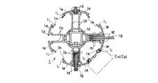
本発明で使用する柱状体1は、図5に例示するように、内部が矩形断面の中空の芯管1aの外周に、平断面が略十字状をなす二重壁による隔壁1bとこの二重の隔壁1b同士を二分する断面十字状の隔壁1cを設け、各壁1b,1cの外端部に部分周壁1d,1eを形成したもののほか、そのような構造を付与しない単なる支柱状の柱状体、或は、上記とは異なる壁構造を持つ柱状体を使用することもできる。
As illustrated in FIG. 5, the
柱状体1は、図5に例示した断面形状により、隣合う隔壁1b,1cが形成する断面V字状の溝が形成する夫々の空間内に、電源ケーブルVcと信号ケーブルSc、又は、いずれか一方のケーブル(以下、これらのケーブルを電源,信号ケーブルという)を、この柱状体1の外面から収納,出入れすることができる。そして、各壁1b,1cの外端部には全体として柱状体1の周壁を形成する部分周壁1d,1eが形成されているので、収納した上記ケーブルVc,Scは溝状部から逸脱し難い。なお、柱状体1の溝状部に入れた上記ケーブルVc,Scをその溝から完全に出さないようにするには、図5に仮想線で例示したように、着脱自在の溝キャップGcを装着してもよい。また、二重に形成された壁1bは、後述するパネル等の部材の係止溝として利用される。更に、各隔壁1cの外端部に形成された部分周壁1eは、後述する電源用又は信号用の夫々のコネクタCv,Csの装着部として利用される。
The
上記構造を具備したポール状の柱状体1は、図1〜図4に例示する態様において、オフィス空間内の床下又は天井裏に敷設されている電源,通信ケーブルの取出しポイントとして形成されるので、以下、この点について説明する。図1は、柱状体1の下端に、ここでは円板状の安定板2を設けると共に、上端に、比例的小径の天板3を設けて形成した本発明による電源,信号ラインの取出ポイントの斜視図である。安定板2には、床下に既に敷設されている電源ケーブルVc及び信号ケーブルScに接続された電源,信号の各ケーブルVc,Scの取出穴2a,2bが形成され、この穴2a,2bから夫々に取出されたケーブルVc,Scが柱状体1の溝部に収装されてそのケーブルVc,Scの先端に接続されたそれぞれのコネクタCv,Csが、所望の高さに配置されている。配置できるコネクタCv又はCsの位置は、柱状体1の外周上では、4ヶ所の部分周壁1eの上であり、同一周壁上の上下方向において2個以上のコネクタCv又はCsを設けることは任意である。上記の安定板2は、柱状体1を床上に固定する場合には、小さ目の円形乃至は翼状に形成したものを使用することができる。
Since the pole-like
図2は、図1に示した電源,信号ラインの取出ポイントPvsにおいて、柱状体1の周囲に、ここでは二分割タイプに形成した円筒状をなすカバー体4を、当該柱状体1に支持させて設けた例である。カバー体4は、金属板,プラスチック板,それらのパンチング穴明板等の適宜の板体により形成し、ここでは底板4aを設けて有底に形成しているが、底板4aの設定は任意である。
FIG. 2 shows a
上記カバー体4の外径は、ここでは天板3と略同径程度に形成し、柱状体1とカバー体4の間に形成される空間にそれぞれの余長ケーブルCv,Csを収納したり、これらの電源,信号ライン用の中継機材、例えば、ブースタアンプや配電箱等の必要な機器,器材Vn,Snを収納することができるように形成されている。
The outer diameter of the
図3は電源,信号ラインの取出ポイントPvsを形成した柱状体1を、背の高い部材により形成し、この柱状体1の下部に、比較的容積の大きな収納ボックス5,6を形成した例である。ここで、収納ボックス5は、前後に開口部5aを設けて形成し、例えばコンピュータの本体(CPU)を収納するボックスとして利用し、また収納ボックス6は、上面を開口した有底の筺状に形成し、このボックス6の壁面と底には通線用のスリット6aと穴状の切欠き6bを設け、内部に電源,信号ラインに必要な中継機器Vn,Sn等を収装することができるように形成されている。なお、1fは柱状体1の上端に被着したドーム状のキャップである。
FIG. 3 shows an example in which the
図4は、床面から天井までの間に立設した柱状体1により、天井側に敷設されている電源,信号ラインに接続してオフィス内に電源,信号ラインの取出ポイントPvsを形成した例である。この柱状体1は、上,下端部にその芯管1aに挿装した上,下アジャスタ7,8を操作して柱状体1を天井Siと床の間で、いわゆる突張り状態で立ち姿勢を保持するようにしている。図4に示した柱状体1においても、その周囲に、収納部4,収納ボックス5,6を設けることは任意である。なお、天井側からの電源,信号ラインの取出ポイントの形成において、柱状体1は必ずしも、天板から床面までの間に突張りタイプで設けなければならない訳ではない。例えば、図示しないが、柱状体1の上端を天井面のライン取出部に固定し、該柱状体1の長さを床に届かない長さに形成することもある。この場合の柱状体1の下端は、一例として、床から70〜80cmまでの高さにする。また、床に立設した天井に届かない高さの柱状体1に、天井面から電源,信号ケーブルを導入することもある。この場合、天井から柱状体1までのケーブルを、フレキシブルチューブのようなガイド体に収めて支持することがある。
FIG. 4 shows an example in which a power source / signal line take-out point Pvs is formed in the office by connecting the power source / signal line laid on the ceiling side by the
図6は、上記で説明した安定板2を備えた柱状体1を、図7に一例として示した断面形状の横杆体9を用いて床に平行な面内でオフィス空間内の任意の位置に自立して敷設されることにより、電源,信号ラインの取出装置を任意のライン状に形成した本発明電源,信号ラインの取出装置の一例(以下、床に平行なライン状をなす本発明電源,信号ラインの取出装置を取出ラインLvsという)の斜視図である。
FIG. 6 shows the
本発明の電源,信号ラインの取出ラインLvsを形成する横杆体9の構成を図7により、またこの横杆体9と柱状体1の接続構造の一例を図8により説明する。
The structure of the
図7に例示した横杆体9は、その断面において柱状体1の芯管1aと同形の芯管9aの上,下に、前記柱状体1における二重壁1bと同様の二重壁9bを突設すると共に、ここでは下方の二重壁9bから左,右に2組の壁9c,9dを突出させ、各壁9b〜9dの相互の間に、ケーブルVc,Scを収納するための溝部が形成されるようにしている。なお、9e,9fは前記壁9c,9dの先端部に設けて全体としてこの横杆体9の周壁をなすように形成した部分周壁、9gは二重壁9bの先端に形成した同旨の部分周壁、9hは二重壁9bの入口部に形成した凹陥部、9iは下位の壁9dの下面側に形成した凹陥部である。
The
上記のような断面形状を具備して本発明電源,信号取出ラインLvsの一例を形成する横杆体9は、各壁9b〜9fにより形成された溝部が、平面からみて概ね上方を開口した溝部に形成されるので、各溝に電源ケーブルVc又は信号ケーブルScを上から投入することにより、両ケーブルVc,Scを外部からは見えないように収納することができることとなる。従って、前記両ケーブルVc,Scについて、横杆体9の任意の位置におけるケーブル先端に、コネクタCv,Csを接続し、このコネクタCv,Csを横杆体9の上の部分周壁9eに装着することにより、横杆体9の任意の位置で電源,信号ラインと適宜の電子機器等との接続をすることが可能になる。
The
本発明の取出ラインLvsの主体となる横杆体9と先に説明した安定板2を備えた柱状体1は、一例として図8に示すような接続部材を使用して接続し、本発明電源,信号ラインの取出装置に構成される。ここで、柱状体1,横杆体9はともに、中心に同形状の芯管1a,9aを具備しているので、この芯管1a,9aに、ジョイント方向に沿って形成したジョイント部材10の両端部10a,10bを嵌入して、両部材1,9の設置方向を規定する。図8の例は、垂直に立上った柱状体1と水平に延びた横杆体9とを、90度曲げで形成したジョイント部材10で接続したものである。なお、10c,10dは芯管1a,9aに嵌入したジョイント部材10の固定ビスである。
The
柱状体1と横杆体9は、ジョイント部材10で接続したままの状態であると、ジョイント部材10の部分に、柱状体1の溝部から横杆体9の溝部に導入される各ケーブルVc,Scがジョイント部分で外部に露出することとなり、見映えがよくない。そこで本発明では、図9に示すようなジョイント部カバー11を使用することとした。
When the
図8,図9に示したジョイントカバー11は、合成樹脂等により形成した背骨状のるフレキシブルな主骨材11aに、先略テーパ状をなし、かつ、下部が開放された略リング状の支骨材11を適当なピッチでこの主骨材11aに列設することにより形成し、主骨材11aの前,後両端部11c,11dを、柱状体1と横杆体9の二重壁1d,9gにより形成された溝に挟持させることにより、両部材1,9の接続部分をカバーするようにしている。
The
なお、ジョイント部材10の形態としては、床から立上げられた柱状体1と床に平行に配置する横杆体9との接続用として、図10に示す態様のものがある。また、天井から床の間に立設された形態又は天井に吊下された形態の柱状体1と横杆体9との接続用としては、図11に示す形態のものがある。図10に示した各ジョイント部材において、10(a)は図8に示したジョイント部材10と同旨のもの、10(b)は横杆体9同士の直列接続用、10(c),10(d)は立設柱状体1から水平二方向の横杆体9への接続用、10(e)は同じく三方向接続用、10(f)は同じく四方向接続用のそれぞれのジョイント部材である。図11のジョイント部材において、10(g)は立設した柱状体1に対して水平に一方向、10(h)は同じく二方向、10(i)は同じく三方向、10(j)は同じく四方向へ、それぞれ横杆体9を接続するためのジョイント部材である。
In addition, as a form of the
上記のような柱状体1,横杆体9,ジョイント部材10等を用いてオフィス内に形成される電源,信号ラインの取出ポイントPvsと取出ラインLvsの一例を図6に拠り説明する。図6の本発明取出ラインLvsは、複数本の安定板2を備えた柱状体1と複数本の横杆体9とを、図6の左側から順に、図11のジョイント部材10(g),図10のジョイント部材10(d),同10(a)を用いて接続することにより形成されている。図6において、図1〜図5,図7〜図11の符号と同一符号は、同一部材又は同一部分を指している。
An example of the power source, signal line extraction point Pvs and extraction line Lvs formed in the office using the
図6の本発明取出ラインLvsにおいて、図の左側下方に位置する柱状体1は、天井側の電源,信号ラインを取出して天板側に配設された上方の柱状体1の支持支柱を兼用し、横杆体9との接続部の始端として機能するように配置されている。また、図6の中間部に位置した柱状体1は、長さ方向で連接される横杆体9,9の接続部を、ジョイント部材10(d)を介して支持する中間支柱として設けられている。そして、このようにして組立てられる柱状体1と横杆体9の上,下の二重壁9bが形成する隙間状の溝には、一例としてスクリーンやパネル12,13を支持させて取付けてある。ここで、パネル13の前面に収納ボックス6が横杆体9に吊下して取付けてある。また、図示しないが、床側の電源,信号ラインが柱状体1の真下から取出せず、横杆体9の途中の床から取出される場合、取出した電源,信号ラインのケーブルは、フレキシブルチューブ等のガイド体を挿通させて横杆体9の溝部に導入する。従って、上記横杆体9の溝部はケーブルを収納する配線ダクトとして機能する。
In the present invention takeout line Lvs in FIG. 6, the
上記のパネル12は、図7に略示するように横杆体9における上位の二重壁9bに挿入して支持させているが、パネル13は下位の二重壁9bに取付けるため、一例として図43の支持構造を採る。即ち、パネル13の上部の前後両面に、二重壁9bの凹陥部9hに係止させた係止爪部材13a,13bを当てがい、この爪部材13a,13bとパネル13を貫通するビスを、この爪部材13a,13bに螺合することにより、パネル13を横杆体9の下位の二重壁9bによって吊下支持するのである。
また、横杆体9に吊下される収納ボックス6の取付けは、図43に例示するように、当該ボックス6の背面板6cに、先端を横杆体9の凹陥部9iに係合するように曲げた吊下具6gをビス6hで止めると共に、この吊下具6gの上部前面に前記凹陥部9iに係合する爪部材6iをビス6jにより止めてなされている。収納ボックスに代え、例えば袋状の容器(図示せず)を設けて余長ケーブル等を収容するようにしてもよい。
The
Also, the
図12〜図14は、図6の場合と同様に、複数本の柱状体1と横杆体9,ジョイント部材10,カバー11などを用いて形成した電源,信号ラインの取出ラインの別例を示すもので、図12は正面図、図13は図12の平面図、図14は図12の左側面図である。これらの図12〜図14に示した取出ラインでは、図12の左側の横杆体9の上面に、当該横杆体9における上位の二重壁9bに、断面略T状の天板支持ブラケット14を支持させ、該ブラケット14の上にカウンター天板15を載架している。
12 to 14 show another example of the power supply and signal line extraction lines formed by using the plurality of
ブラケット14は、具体的には一例として図44に示す構造を具備している。即ち、図44において、天板15を支持する翼状部材14aの中心部下面に、横杆体9の上面の部分周壁9gに合致するスペーサ14bを介在させると共に、上位の二重壁9bの入口に形成した凹陥部9iにビス受け14cを収装し、前記翼状部材14aとスペーサ14bを貫通するビス穴を設け、この穴から入れたビス14dを前記ビス受け14cに螺入,緊締することにより、ブラケット14が形成される。従ってこのブラケット14における翼状部材14aに天板15を載架し、下面からビス14eにより天板15を前記部材14aに止着することができる。
Specifically, the
上記の取出ポイントPvsと本発明の取出ラインLvsを形成する柱状体1と横杆体9は、これらを図15に例示するように、オフィス床面に平面矩形状をなす枠状体Fに形成して立設し、この枠状体Fを、ワークブースとして使用するようにしてもよい。図15において、Cgは、このブースの四隅において、柱状体1と横杆体9における2重壁1d,9gに挟持させて取付けた透光性の樹脂ガラス、Cwは、各樹脂ガラスCgの下方に設けた巾木である。また、上記枠状体Fにおいて、図15に表わしていないが、柱状体1及び横杆体9には電源,信号ケーブルVc,Scが収装され、適宜位置に接続用のコネクタCv,Csを位置可変に設けられることは勿論である。
As shown in FIG. 15, the
以上に説明した本発明の一例の装置における電源,信号ラインの取出ポイントを形成する柱状体1、並びに、取出ラインを形成する横杆体9は、図16〜図26に例示する形態でも実施できるので、柱状体1と横杆体9の別例について図16〜図26により説明する。
Since the power source, the
図16は柱状体1の別例の平断面図で、図16において図1〜図15に使用した符号と同一符号は同一部分,同一部材を指すものとする。図16に例示した柱状体1は、芯管体1aの外周に、平断面が十字状をなすように二重壁による隔壁1bを設け、各隔壁1bの外端部に部分周壁1d,1eを形成し、かつ、一方の部分周壁1eの先端部に、段付き辺1hを形成してこの辺1hと前記周壁1eの境界部に小溝1iを形成したものである。
FIG. 16 is a plan sectional view of another example of the
上記の断面形状により、柱状体1は、隣合う二重の隔壁1bが形成する断面90度の溝が形成する夫々の空間内に、電源ケーブルVc又は信号ケーブルScを、この柱状体1の外面から収納,出入れすることができる。そして、各隔壁1bの外端部には全体として柱状体1の周壁を形成する部分周壁1dと段付き辺1hが形成されているので、上記ケーブルVc,Scは収納された溝状部から逸脱し難い。柱状体1の溝状部に入れた上記ケーブルVc,Scをその溝から完全に出さないようにするには、対向する小溝1iに支持させて着脱自在の溝キャップ(図示せず)を装着してもよい。なお、二重に形成された隔壁1bの間は、図2,図3に例示したようにパネル1g等の部材の係止溝としても利用される。また、対向する前記小溝1iは、後述する電源用又は信号用の夫々のコネクタCv又は同Csの装着部として利用される。CbはコネクタCv又はCsの取付けベースで、前記小溝1iに遊嵌されてガイドされ柱状体1の長さ方向で、コネクタCv又はCsを自由にスライドさせて位置決めするためのものである。
上記の断面構造を付与した図16の柱状体1は、図1〜図4に例示した態様と同様の形態、或は、図27に例示する形態において、オフィス空間内の床下又は天井裏に敷設されている電源,通信ケーブルの取出ポイントPvsとして形成される。ここで図27は、取出ポイントPvsを構成する柱状体1の安定板2にキャスタCaを設けることにより、床上に安定に配置できると共に、必要に応じて移動できるようにした例である。キャスタCaを設ける安定板2の形態は、図1〜図3,図6,図27に例示した形態以外の、例えば、矩形状,枠状の形態であってもよい。
Due to the cross-sectional shape described above, the
The
図17は、本発明装置を構成する横杆体9の別例の側断面図である。図17に例示した横杆体9は断面から視て大略T状をなす杆状支持部材91と、この支持部材91の下面側に吊下態様で連結支持される第一溝状部材92と、この第一溝状部材92を介して前記支持部材91に吊下態様で支持される第二溝状部材93とにより形成されている。
FIG. 17 is a side sectional view of another example of the
図17に示した杆状支持部材91は、断面縦長矩形の芯管体91aの上部に、中央に形成した縦長の上向きの溝部91bを介して屋根形のカバー部91cを左,右に具備すると共に、この芯管体91aの下部に形成した下向きの溝部91dを具備し、かつ、芯管体91aの左,右の側面に形成した上,下で対向する小溝91eを具備して形成されている。
The saddle-
図17の第一溝状部材92は、その底部下面に垂下形成した前記芯管体91aと同幅の溝部92aと、この溝部92aの上部に形成した断面略凹状をなす樋部92bを具備して形成されている。ここで、溝部92aは、側面の上下に形成した上記小溝91eと同旨の対向する小溝92cを具備し、また樋部92bは、底壁92dと側壁92eを具備している。
A first groove-
図17の第二溝状部材93は、その底部上面に突出形成した略凸状をなす輪郭を有する溝部93aと、この溝部93aの左右側に突出させて弯曲形成した左右の底壁93c,93c、及び、両底壁93cから立上げて形成した左右の側壁93d,93dを具備した樋部93bとから形成されている。
The second groove-
上記の支持部材91と第一,第二の溝状部材92,93とは、棒状の杆体94aが第一溝状部材92の溝部92aを貫通し、この杆体94aの上,下端部94b,94cが前記支持部材91の下方の溝部91dと第二溝状部材93の溝部93aとに嵌合して支持される棒状の連結部材94、及び、各部材91〜93の相互の間隔を規制する2つのスペーサ95a,95bとによって図17に例示する態様で結合一体化されて横杆体9の別例に構成されるのである。
The
横杆体9を図示17に例示した断面形態とすることにより、2つの溝状部材92,93により形成されるケーブル収納ダクト、即ち配線ダクトとなる樋部92b,93bを大きな容量に形成し易くなると共に、芯管体91aの両側面や溝部92aの両側面に形成した上下で対向する小溝91e,91e、或は、同92c,92cに、電源用又は信号用のコネクタCv又はCsを、溝状部材92,93の内部から外方へ突出させることなく、その取付けベースCbを介してスライド自在に装着でき、かつ、この状態で樋部92b,93bにケーブルの出入れを自由に行うことが可能になる。
By making the
図17に示した横杆体9においては、支持部材91における下向きの溝部91dの底面を球状断面に、また第二溝部材93の溝部93aの上部内面を球状断面にそれぞれ形成し、これらの溝部91d,93aに収まる連結部材94の上,下端部94b,94cを前記球状断面に対応する球状面に形成することにより、連結部材94を溝部91dに対し図17の左右に揺動させ、また第二溝状部材93を連結部材94の下端において図の左右に揺動させること可能になるので、各樋部92b,93bに収納するケーブルやコネクタの出入れの際に、前記揺動を利用して出入口を拡大することができ、便利である。
In the
上記のケーブルやコネクタの樋部92b,93bへの取入れ容易性を得るには、第一,第二溝状部材92,93における底壁92d,93cと側壁92e,93dとの境界部を弾力的に形成してこの部にヒンジ機能を持たせたり、或は、両壁をヒンジを介して接続することにより、それぞれの側壁92e,93dが外側へ開放でき、不要時には直立するようにしてもよい。図22は、第二溝状部材93の底壁93cと溝部93aの境界をヒンジ93eに形成すると共に、側壁93dを延長形成してその上端と第一溝状部材92の側壁92eの下端の間に、開閉自在のロック93fを形成したものである。この構成は、第一溝状部材92に適用してもよい。溝状部材92,93を図22に示した側壁構造とするときは、コネクタCv,Csを、その側壁92d,93dに取付けるようにすることが望ましい。
In order to obtain the ease of insertion of the cables and connectors into the
本発明では、図17の横杆体9の別例において、杆状支持部材91と2つの溝状部材92,93とを連結する棒状の連結部材94を、図示しないが、伸縮構造とし、溝状部材92,93の樋部92b,93bの出入口を拡縮できるようにして、これらの樋部92b,93bに対するケーブルCv,Csの出入れを行い易くすると共に、収容するケーブルCv,Csの量が多く大容量化しても、各部材91〜93の間の隙間を大きくして対応できるようにすることができる。このような対応は、杆状支持部材91と溝状部材92と同93とを、前記棒状の連結部材94が配置される位置において、パントグラフ状のリンク部材を介して連結することによっても可能であり、こうすることにより各部材91〜93間の相互の隙間を、任意の間隔に自由に調節できる。上記の2つの溝状部材92,93は、図23に例示するように、いわゆる入れ子構造にし、ここでは、大形に形成した下方の溝状部材93の内部に、小形断面の溝状部材92を収容して配設することにより、外見上、一方の溝状部材93のみしか見えないようにして、横杆体9をスマートな形態に形成することができる。図23において、図22と同一部材,同一部分は同一符号で示す。一方、上記構成によってもケーブルCv,Csが樋部92b,93bに収まり切れない場合、或は、それとは無関係に、余長ケーブルCv,Csを収納するための容器を設けたり、コードリールを設けたり、或は、シート状の覆板を設けることができる。図24,図25は、コードリールCrを柱状体1の溝にその取付ブラケットRbを介して取付ると共に、2枚のシート状覆板Cpを第二溝状部材93の底壁下面に、この部材93と平行に垂下させて設けた例を示している。
In the present invention, in another example of the
図16,図17に例示した本発明装置に用いる柱状体1と横杆体9は、一例として図18に示すようなジョイント部材10を用いて連結することにより、図20に例示するような電源,信号ラインの取出ポイントと取出ラインを具備した本発明装置に形成されるので、次にこの連結について説明する。
The
図18におけるジョイント部材10は、図16の柱状体1の芯管体1aに密嵌固定される縦部材10vと、図17の横杆体9の芯管体91aに嵌入して固定される水平部材10hであって、ここでは90度の平面角度で縦部材10vの上部に連結された2本の水平部材10hにより形成されている。そして図16の柱状体1の中央芯杆体1aに嵌入されて固定ビス10xにより縦部材10vが固定されるジョイント部材10の2本の水平部材10hに、図17で示した断面形態の横杆体9が、その支持部材91の芯管体91aを嵌入し、固定ビス10yにより固定することにより、図20に例示する形態の電源,信号ラインの取出ポイントと取出ラインを具備した本発明取出装置の例に構成されるのである。上記連結部には、キャップ状のカバー11′を装着する。カバー11′は、柱状体1と略同外径の天蓋11′eを有する筒体により形成すると共に、周壁上に、ジョイント部材10の水平部材10hを遊挿できる切欠11′fが形成されている。この切欠11′fには、不要時には着脱自在の蓋11′gが装着されている。
The
ジョイント部材10による柱状体1と横杆体9との連結において、例えば、ジョイント部材10の縦部材10vを円形断面に形成し、柱状体1における芯杆体1aの中央穴に回転可能に嵌合させれば、このジョイント部材10の水平部材10hに連結される横杆体9の平面配向角を任意の角度に配向させることが可能になる。この配向自在の機能は、図26に例示するように、ジョイント部材10の構成において、縦部材10vの上端にリング状の溝10rを周設すると共にその中心に雌ネジを形成したネジ受け部10sを立設形成する一方、水平部材10hの先端を、前記リング状溝10rの縁に係止される鉤状の係止部10tに形成し、この鉤状係止部10tを、水平部材10hの平面角を任意に選択して前記溝10hの縁に係止させ、係止された該係止部10tを前記ネジ受け部10sに螺合し緊締される押えネジ10uの頭部10pによって押圧することにより、横杆体9と結合された水平部材10hをその横杆体9と一体に任意の平面配向角で柱状体1に結合することができる。上記は柱状体1と横杆体9の結合部には、図18,図19に例示するカバー11′が装着される。図19のカバー11′は、図18のカバー11′の別例であって、柱状体1の芯管体1aに挿入される主杆11′hと、この主杆11′hの上端に形成した冒体11′iと冒体11′iの周上に互に隙間を介して垂下した多数の支杆11′jとから形成されており、支杆11′jの隙間からケーブルを出入れしたり、ジョイント部材10の水平部材10hを逃げるようにしている。
In the connection between the
また、ジョイント部材10の水平部材10hに対して連結される横杆体9を前記水平部材10hの長さ方向に関し進退可能に連結することにより、例えば、柱状体1の立設位置に対しわずかに長さが足りない横杆体9であっても、その柱状体1に連結することが可能になるので、柱状体1の立設位置と横杆体9の長さとが整合しない場合の連結に有用である。柱状体1と横杆体9とが隙間を介して連結される場合、その隙間をカバーできるカバー体を隙間部分に装着すれば、見映えも悪くならない。
Further, by connecting the
上記の機能は、本発明装置の取出ラインを形成する横杆体9を伸縮自在の構造としても得られる。図28は図17に例示した横杆体9伸縮自在の構造にする例の斜視図である。図28においては、横杆体9の伸縮構造は一例として次のように構成されている。即ち、横杆体9を構成する杆状支持部材91と2つの溝状部材92,93を、これらを柱状体1に連結するためのジョイント部材10に結合される基部側9Bと、この基部側9Bに伸縮可能に接合される接続側9Eとに分割すると共に、基部側9Bの各部材91〜93の端部に、それらの断面より少し小さい断面の連結部91J,92J,93Jを各部材91〜93に支持させて突出形成し、この突出した各連結部91J〜93Jに、夫々に対応する接続側9Eの各部材91〜93を、スライド可能にインサートして連結しておくのである。横杆体9をこのように形成すると、連結部91J〜93Jの有効長さの範囲で横杆体9の全長を伸縮調節することができる。また、柱状体1を上記横杆体9と同様の構造、又は、他の構造によって縮自在構造にすると、取出ラインを形成する横杆体9の床面からの高さを任意の位置に設定できるのでオフィス設備システムとしての配設形態の範囲を、前記横杆体9の伸縮自在機能と相俟って効果的に拡大することができる。
The above function can also be obtained by making the
図21は、本発明装置を構成する取出ラインLvsを、2列平行にオフィスの床上に敷設し、この2本の取出ラインLvs-1とLvs-2を、背の高い門型に形成した取出ラインLvs-3により接続した形態の取出ラインの斜視図である。このような取出ラインの形態を採ると、床又は天井の1箇所からしか取出せない電源,信号ラインであっても、2列以上の取出ラインLvs-1,Lvs-2を形成できると共に、接続用の背が高い門型の取出ラインLvs-3が、人の往来や他の設定ラインの邪魔になることはない。 FIG. 21 shows an extraction line in which the extraction lines Lvs constituting the apparatus of the present invention are laid on the office floor in two rows in parallel, and the two extraction lines Lvs-1 and Lvs-2 are formed in a tall gate shape. It is a perspective view of the extraction line of the form connected by line Lvs-3. By adopting such an extraction line configuration, it is possible to form two or more extraction lines Lvs-1 and Lvs-2 even for power and signal lines that can only be extracted from one place on the floor or ceiling, and for connection The tall gate-shaped extraction line Lvs-3 does not interfere with traffic and other setting lines.
上述の電源,信号ラインの取出ポイントPvsと本発明の取出ラインLvsは、それらの構成部材である柱状体1や横杆体9に、収納ボックス6,パネル12,13,天板15などを支持させて、オフィス用設備の構成部材の一部としての機能を発揮させるように形成することができ、しかも、その柱状体1や横杆体9における任意の箇所で電源,信号ラインの取出しが可能であるから、この電源,信号ラインの取出ポイントPvs,取出ラインLvsと、移動可能に形成した種々のデスクによって、図38〜40に例示するように、より自由なオフィス空間内での設備の配置を実現できることとなる。そこで、上記のような電源,信号ラインの取出ラインLvs、或は、取出ポイントPvsと組合せた取出ラインLvsに組合せて使用するのに好適なデスクの例について、図29〜図37により説明する。
The power supply and signal line take-out point Pvs and the take-out line Lvs of the present invention support the
図29〜図31はデスクD1を示すもので、これらの図において、16は水平な足16aとその中間部に立設した支柱16bにより側面略逆T状に形成し、その2本を左右平行に並べ、左右の支柱16bの上端を梁部材17で連結することによって、正面視略門型をなすように形成した脚フレームである。左右の支柱16bは、いずれも、油圧式,空圧式,機械式いずれかの手段により昇降するようにした内支柱16cを具備しており、梁部材17は、この左,右の内支柱16c間に架設されている。
FIGS. 29 to 31 show a desk D1, in which 16 is formed in a substantially inverted T shape on the side surface by a
上記梁部材17には、左右側に天板19の前後傾斜角の調節機構を内蔵した天板支持アーム18,18が設けられ、天板19は、この左右のアーム18の手前側に枢着されている。18a,18aはアーム18,18の先端と天板19の中間部の下面の間に架設した傾斜角調節シリンダである。
The
上記脚フレームにおける足16aの下面には、デスクの移動と固定を選択的に記能させるキャスタ16dとアジャスタ16eが設けられている。ここで、キャスタ16dにはボールキャスタを使用すると共に、アジャスタ16eは前記ボールキャスタを中心部に内装したリング状のものが使用され、アジャスタ16eの正逆回転によって、キャスタ16dを接地させるか、アジャスタ16eの下面を接地させるかのいずれかを選択するように形成されており、以上により本発明で使用するデスクD1の一例を形成する。
On the lower surface of the
上記脚フレームに支持させる天板19の平面形状は、基本的には長方形乃至は四辺形であるが、左,右の一方の側、又は、双方が円弧状の側縁に形成されたデスクD1′(図38参照)、或は、四辺形が全体として弯曲された形状のものなど、異形の長方形であってもよい。また、デスクD1は左,右の脚16のうち一方の脚16の足16aを円板状の足(図示せず)で形成したデスクもある。なお、16fは内支柱16cの昇降操作用ハンドル、18bは天板角度変更用の操作用ハンドルである。
The planar shape of the
図32〜図34はデスクD2の例を示すもので、20は平面視略星形状をなす足20aに昇降(伸縮)自在に組合せたテレスコピック状の支柱20b,20cを立設した脚フレームで、内支柱20cの上端に、基本的に円形天板21を載架した構成である。各足20aの先端下面には、先の例と同様のボールキャスタ20dと、このキャスタ20dを内装したリング状のアジャスタ20eが設けられ、デスクD2の移動,定置が選択できるようになっている。20fは支柱昇降の操作ハンドルである。ここで、足20aは、平面視略星形のものを使用したが、円板状のものであってもよい。また、このデスクD2の天板は図33,図34の平面図に示すように、円形天板の一側を直線辺22aに截断した形状の天板22、或は、天板の一半側を90度コーナ部を有する直線辺23aに形成した形状の天板23など、外周辺の一部に直線辺を形成した天板を用いたものがある。
FIGS. 32 to 34 show an example of the desk D2, and 20 is a leg frame in which telescopic columns 20b and 20c are erected in combination with a
図35〜図37は、デスクD3を例示するもので、図35は正面図、図36は図35の右側面図、図37は図35の平面図である。このデスクD3では、脚フレーム24に平面視逆V字状で開き角が略90度の2本足24aを使用し、昇降自在に組合せたテレスコピック状の支柱24b,24cが前記足24aの略交点上に立設されている点が、これまでのデスクD1,D2の脚フレーム16,20と異なっている。そして、この内支柱24cの上端に設けた天板角傾斜機構25の上に、平面視略1/4円弧状の天板26を載架して、このデスクD3は構成されている。なお、24dはボールキャスタ、24eはリング状アジャスタである点は、先のデスクD1,D2の場合と同旨である。また、24fは高さ調節用の操作ノブ、25aは天板26の角度調節用の操作ノブである。
35 to 37 illustrate the desk D3. FIG. 35 is a front view, FIG. 36 is a right side view of FIG. 35, and FIG. 37 is a plan view of FIG. In this desk D3, two
このデスクD3は、その天板26,足24aの平面形状から、複数のデスクD3を突合せ状態で対向的、或は、ほぼ花弁状をなすように配置することができる。これにより、デスクD3は後述する小会議や打合せコーナ用のデスクとして使用するのに好適である。もっとも、デスクD3において、天板26は1/4円弧状のものに限られる訳ではない。矩形や円形であっても何ら支障はない。また、このデスクD3は、図示しないが脚フレーム24における支柱24bの前面に、パンチングプレスしたパネルや収納ボックスを、必要に応じて取付けることができるように形成されている。
The desk D3 can be arranged so that a plurality of desks D3 face each other in a face-to-face state or almost form a petal shape from the planar shape of the
以上に説明した本発明装置における電源,信号ラインの取出ラインLvs、或は、このラインLvsと取出ポイントPvsに対して、上記の各デスクD1〜D3は、図38〜40に例示する形態において、電源,信号の取出ラインLvsに沿って自由に移動させて配置することにより、オフィスにおける様々なワークブースに構成されるので、以下、この点について説明する。 With respect to the power source, the signal line extraction line Lvs, or the line Lvs and the extraction point Pvs in the apparatus of the present invention described above, each of the desks D1 to D3 is in the form illustrated in FIGS. Since it is configured in various work booths in the office by freely moving and arranging along the power supply and signal extraction line Lvs, this point will be described below.
図38においては、前記柱状体1と横杆体9の組合せにより床に平行に配置された取出ラインLvs、或は、柱状体1により形成される取出ポイントPvsに対して、上記で説明したデスクD1,D1′,D2を配置した例が示されている。
In FIG. 38, the desk D1 described above with respect to the extraction line Lvs arranged in parallel to the floor by the combination of the
取出ラインLvsに沿って、デスクD1を、その天板19の長辺側を当接乃至させ、このデスクD1にデスクD1′を直交する向きで並べ一つのワークブースを形成している。このデスクD1,D1′は、取出ラインLvsに沿って、自由に位置を変え、また、配向も自由に設定することができる。デスクD1,D1′の移動は、その足16aのアジャスタ16eを回転させて内部のボールキャスタ16dを接地させることにより、軽い労力により容易かつ自由に行うことができる。また、デスクD1,D1′を移動させても取出ラインLvs上の複数個所には、必要なコネクタがそれ自体移動可能に設けられているので、デスクD1,D1′上で使用する電子機器等の電源,信号ラインは、特別の配線等を要することなく、前記コネクタに直ちに接続することができる。
Along the take-out line Lvs, the desk D1 is brought into contact with the long side of the
取出ポイントPvsに対しては、図38に例示するように、ここでは2本のデスクD1,D2を組合せ、両デスクを前記ポイントPvsを挟んで配置し、小規模のワークブースが形成されている。ここで、デスクD1の天板19は事務作業用のスペースとして、デスクD2の天板、22はOA機器を載置したコンピュータ作業スペースとして形成されている。このため、天板22は天板19よりも高く位置付け、天板22を天板19に一部オーバハングさせて配置し、前記2種の作業を、椅子Chを回転させて身体の向きを変えるだけで、選択的に行うことができるようにしている。図38,図39においてCptはCRTを含むコンピュータ本体又はCRT、Kbはキーボードである。
For the take-out point Pvs, as illustrated in FIG. 38, two desks D1 and D2 are combined here, and both desks are arranged with the point Pvs in between, thereby forming a small work booth. . Here, the
また、図40に例示するように、柱状体1と横杆体9とを組合せて形成した平面矩形状の枠状体Fで形成したブース内に、図3の背の高い柱状体1を使用した取出ポイントPvsを配置し、このポイントPvsに各柱状体1を中心にして図33〜図35に例示したデスクD3を、その天板26を手前側下りに少し傾けて原稿台として、或は、ラップトップタイプのパソコンを置けるようにして、適宜配置することにより、いわゆる立ち会議コーナ等のように立ったままでオフィスワークを行うブースを形成することができる。この場合に使用するデスクD3も、移動,定置は自由にできるから、会議等が終了すれば、自分の使用したデスクD3を片着けるなどして、残った取出ポイントPvsを中心とする他の目的のコーナを、先のデスクD3、或は、他のデスクD1,D2等を取出ポイントPvs、或は、このブースの枠状体Fを形成している柱状体1又は横杆体9に対して配置することにより、容易に形成することができる。なお、図40において、Rsは遮蔽パネルとして設けたロールスクリーンである。
Further, as illustrated in FIG. 40, the tall
以上に説明した本発明における電源,信号ラインの取出装置は、それを形成する横杆体9を、図41,図42に例示する間仕切パネルにおける笠木又は巾木、或は、それらの同等部材として適用できるので、次にこの点について説明する。
In the power supply and signal line take-out device according to the present invention described above, the
図41は、デスクD1の天板19の高さより少し高い程度の高さに形成された間仕切パネルPtにおいて、その笠木部材Ubの片面又は両面に、断面略樋状をなす横杆体9Lを柱状体1となる側枠に支持させて配設し、この横杆体91の任意の位置に電源,信号ケーブルのコネクタCv又はCsを長さ方向で位置可変に配置した例である。図41においてBbは巾木、Spは間仕切パネルPtの上に形成配置した遮蔽パネル、Lpは該パネルSpの一方に設けた棚板である。
FIG. 41 shows the partition panel Pt formed at a height slightly higher than the height of the
図42は,図41の間仕切パネルPtにおいて、当該パネルPtの上部に、そのパネルPtの笠木部材Ubを兼用してコネクタCv又はCsを具備する横杆体9Lを設けた例である。図40において、図41と同じ符号は同一部を指すものとする。 FIG. 42 shows an example in which the horizontal frame 9L having the connector Cv or Cs is provided above the panel Pt in the partition panel Pt shown in FIG. 41, which also serves as the head member Ub of the panel Pt. 40, the same reference numerals as those in FIG. 41 denote the same parts.
一方、図45は、図21に例示した門型の取出ラインLvs-3を介して接続した、或は、夫々に独立して平行に並べた2本の取出ラインLvs-1,Lvs-2の間に夫々にデスクD1をメインデスクとし、デスクD3を補助デスクとして配置した、ここでは8人用のワークブースの使用形態を示した平面図で、図45の(a)は、各個人が夫々のブースにおいて執務している状態を示し、図45の(b)は、各人が補助デスクD3を移動させてミーティングの場所を2箇所形成した例である。このように、本発明装置を利用すると、各個人の執務空間とミーティング空間の切換え設定を、随時、容易に実行することができる。 On the other hand, FIG. 45 shows two extraction lines Lvs-1 and Lvs-2 connected via the gate-shaped extraction line Lvs-3 illustrated in FIG. 21 or arranged in parallel independently of each other. In the meantime, the desk D1 is the main desk and the desk D3 is the auxiliary desk. Here, it is a plan view showing how to use the work booth for 8 persons. FIG. 45 (b) shows an example in which each person moves the auxiliary desk D3 to form two meeting places. As described above, when the apparatus of the present invention is used, the setting for switching between the office space and the meeting space of each individual can be easily performed at any time.
上述した本発明の取出ラインLvs、或は、取出ポイントPvsと組合せた取出ラインLvsに対して任意に配置した各デスクD1〜D3は、いずれも、従来デスクのような配線ダクトや配線取出口が全く設けられず、また、その天板の高さ、或は、その天板の傾きを、使用する者の好みや、ワーク形態や内容に適したように、自由に変更,設定することができるように構成したので、構造が簡単で軽量に作製できて移動させるのに便利であり、使い勝手の面、或は、疲れ難いといった面からもきわめて好ましい機能を具備したものである。 Each of the desks D1 to D3 arbitrarily arranged with respect to the take-out line Lvs of the present invention described above or the take-out line Lvs combined with the take-out point Pvs has a wiring duct or a wire take-out like a conventional desk. It is not provided at all, and the height of the top plate or the inclination of the top plate can be freely changed and set to suit the user's preference, work form and contents. Since it is configured as described above, it has a simple structure, can be made light and convenient to move, and has a very preferable function from the viewpoint of usability or fatigue.
また、上記の各デスクD1〜D3は、従来の固定配置タイプのデスクに比べ、そのデスクと一体の袖キャビネットを設けず、また、センター抽出も原則として設けないので、上記の配線ダクトが設けられないことと相俟って重量が大きくならず、移動が容易であるほか、固定収納部がないので、不特定複数の者が共用する上でも、便利である。 In addition, each of the above desks D1 to D3 is not provided with a sleeve cabinet integrated with the desk and, as a general rule, is not provided with a center extraction, as compared with a conventional fixed arrangement type desk, and thus the wiring duct is provided. In combination with the lack of weight, the weight does not increase, and it is easy to move, and since there is no fixed storage part, it is convenient for unspecified persons to share.
本発明は以上の通りであって、オフィス空間内に、そこで使用するOA機器の電源,信号ラインを自由に離接することができる電源,信号ラインを形成するケーブルを収納するように形成した横杆体による配線ダクトを前記電源,信号の取出ラインとして配設したので、この取出ラインに対し、例えば天板の高さを自由に設定できるように形成した天板の大きさが種々異なるデスク等を選択し、かつ、選択したデスク等を自由な配向で任意の位置に移動させて配置することにより、種々のワーク形態に対応するためのワークブースを、任意かつ容易に形成することができる。そして、どのような形態のワークブースが形成されても、そこで使用するOA機器の電源,信号ラインを、特別な配線工事やそのつどの配線手配などを要することなく直ちに接続することができるという、格別の効果が得られる。 The present invention is as described above, and in the office space, the power supply of the OA equipment used there, the power supply capable of freely connecting and disconnecting the signal line, and the horizontal casing formed so as to accommodate the cable forming the signal line. Since the wiring duct is arranged as the power source and signal extraction line, for example, desks with different top plate sizes can be selected for the extraction line so that the height of the top plate can be set freely. And by moving the selected desk or the like to an arbitrary position in a free orientation, a work booth for accommodating various work forms can be arbitrarily and easily formed. And no matter what form of work booth is formed, the power and signal lines of OA equipment used there can be connected immediately without requiring special wiring work or wiring arrangements. A special effect is obtained.
また、取出ラインの一例を形成する横杆体は、ライン状の開口を有する溝を形成することにより、ケーブルの収納とコンセント等のコネクタを取付けることができるように形成したので、ケーブルの出入れが容易であるほか、コンセントを前記溝の長さ方向で自由に移動させることができ、従って、本発明取出ラインに沿って配置されるデスク等の上で使用するOA機器の電源,信号ラインを、容易に接続することができる。 In addition, the horizontal casing forming an example of the extraction line is formed so that the cable can be accommodated and a connector such as an outlet can be attached by forming a groove having a line-shaped opening. In addition to being easy, the outlet can be freely moved in the length direction of the groove. Therefore, the power supply and signal line of the OA equipment used on a desk or the like arranged along the take-out line of the present invention, Can be connected easily.
更に、本発明の取出ラインの別例を形成する横杆体を、杆状支持部材とこの支持部材に支持させて配置される溝状部材とにより形成することにより、電源ケーブルと信号ケーブルを分けて前記溝状部材に収容できてその出入れも容易にできるのみならず、収容するケーブル量が多くても、コネクタも併せて溝状部材の内部に収容でき、これらが外部にはみ出すことなく溝状部材の中に収容することができることになるので見映えもよく、特に、ケーブルを溝状部材にいわゆる投げ込み配線できるという効果が得られる。 Furthermore, by forming the horizontal casing forming another example of the take-out line of the present invention by the hook-shaped support member and the groove-shaped member arranged to be supported by the support member, the power cable and the signal cable are separated. Not only can the housing be accommodated in the groove-like member, and the entry and exit of the groove-like member can be facilitated, but the connector can also be accommodated inside the groove-like member even if the amount of cables to be accommodated is large. Since it can be accommodated in the member, it looks good, and in particular, the effect that the cable can be thrown into the groove-like member can be obtained.
1 柱状体
1a 芯管
1b,1c 隔壁
1d,1e 部分周壁
1f ドーム状のキャップ
2 安定板
2a 取出穴
3 天板
4 カバー体
4a 底板
5,6 収納ボックス
5a 開口部
6a スリット
6b 切欠
7,8 アジャスタ
9 横杆体
9a 芯管
9b 二重壁
9c,9d 壁
9e,9f 部分周壁
9g 二重壁9b先端の部分周壁
10 ジョイント部材
10c,10d 固定ビス
11 カバー
11a 主骨材
12,13 パネル
14 天板支持ブラケット
15 カウンター天板
16 脚フレーム
16a 水平な足
16b 支柱
16c 左,右の内支柱
16d キャスタ
16e アジャスタ
16f 昇降操作用ハンドル
17 梁部材
18 支持アーム
18a 傾斜角調節シリンダ
18b 天板角度変更用の操作ハンドル
19 天板
20 脚フレーム
20b,20c テレスコピック状の支柱
20d キャスタ
20e アジャスタ
20f 支柱昇降の操作ハンドル
21 円形天板
22 截断した形状の天板
23 コーナ部に形成した形状の天板
24 脚フレーム
24a 2本足
24b,24c テレスコピック状の支柱
24d ボールキャスタ
24e リング状アジャスタ
24f 高さ調節用操作ノブ
25 天板角傾斜機構
25a 天板26の角度調節用のノブ
26 平面視略1/4円弧状の天板
D1〜D3 デスク
Vc 電源ケーブル
Sc 信号ケーブル
Gc 溝キャップ
Cv,Cs コネクタ
Vn,Sn 中継機器,器材
Pvs 取出ポイント
Lvs 取出ライン
1 Columnar body
1a Core tube
1b, 1c Bulkhead
1d, 1e Partial wall
1f
5a opening
6a slit
9a core tube
9b double wall
9c, 9d wall
9e, 9f Partial peripheral wall
9g Partial wall at the tip of
10 Joint parts
10c, 10d fixing screw
11 Cover
11a Main aggregate
12, 13 panels
14 Top plate support bracket
15 Counter top
16 leg frame
16a level foot
16b prop
16c Left and right inner struts
16d casters
16e adjuster
16f Elevating handle
17 Beam members
18 Support arm
18a Inclination angle adjustment cylinder
18b Operation handle for changing the top angle
19 Top plate
20 leg frame
20b, 20c Telescopic column
20d casters
20e adjuster
20f Strut lifting handle
21 Circular top plate
22 Top plate with cut shape
23 Top plate shaped at the corner
24 leg frame
24a two legs
24b, 24c Telescopic column
24d ball caster
24e Ring adjuster
24f Height adjustment knob
25 Top plate angle tilt mechanism
25a Knob for adjusting the angle of the
26 Top view with an arc shape of approximately 1/4 in plan view
D1-D3 desk
Vc power cable
Sc signal cable
Gc groove cap
Cv, Cs connector
Vn, Sn relay equipment, equipment
Pvs removal point
Lvs extraction line
Claims (7)
Priority Applications (1)
| Application Number | Priority Date | Filing Date | Title |
|---|---|---|---|
| JP2003391981A JP3935465B2 (en) | 1997-01-24 | 2003-11-21 | Power supply and signal line take-out device in office space |
Applications Claiming Priority (2)
| Application Number | Priority Date | Filing Date | Title |
|---|---|---|---|
| JP2615597 | 1997-01-24 | ||
| JP2003391981A JP3935465B2 (en) | 1997-01-24 | 2003-11-21 | Power supply and signal line take-out device in office space |
Related Parent Applications (1)
| Application Number | Title | Priority Date | Filing Date |
|---|---|---|---|
| JP9273279A Division JPH10271649A (en) | 1997-01-24 | 1997-09-22 | Extraction device for power supply and signal line in office space |
Publications (2)
| Publication Number | Publication Date |
|---|---|
| JP2004140998A JP2004140998A (en) | 2004-05-13 |
| JP3935465B2 true JP3935465B2 (en) | 2007-06-20 |
Family
ID=32472253
Family Applications (1)
| Application Number | Title | Priority Date | Filing Date |
|---|---|---|---|
| JP2003391981A Expired - Fee Related JP3935465B2 (en) | 1997-01-24 | 2003-11-21 | Power supply and signal line take-out device in office space |
Country Status (1)
| Country | Link |
|---|---|
| JP (1) | JP3935465B2 (en) |
Families Citing this family (3)
| Publication number | Priority date | Publication date | Assignee | Title |
|---|---|---|---|---|
| KR20070027449A (en) | 2005-09-06 | 2007-03-09 | 가부시끼가이샤 우찌다 요오꼬오 | Space provision system and information display system |
| CN102493551B (en) | 2005-11-11 | 2014-09-03 | 株式会社内田洋行 | Space structure |
| NZ622790A (en) | 2009-06-30 | 2015-03-27 | Schiavello Vic Pty Ltd | Reconfigurable workstation support |
-
2003
- 2003-11-21 JP JP2003391981A patent/JP3935465B2/en not_active Expired - Fee Related
Also Published As
| Publication number | Publication date |
|---|---|
| JP2004140998A (en) | 2004-05-13 |
Similar Documents
| Publication | Publication Date | Title |
|---|---|---|
| US5687513A (en) | Dynamic workspace module | |
| EP0382514B1 (en) | Modular furniture | |
| US5094174A (en) | Modular furniture | |
| US7032523B2 (en) | Workstation with a moveable apparatus | |
| EP3302172B1 (en) | Free-standing workstation assembly with lift mechanisms | |
| US5220871A (en) | Modular furniture | |
| US6629386B1 (en) | Furniture system | |
| US6359217B1 (en) | Cabinet with electrical/data conduit routing capabilities | |
| US5784843A (en) | Integrated prefabricated furniture system for fitting-out open plan building space | |
| US6021613A (en) | Hybrid office panel construction for a modular office furniture system | |
| US6742307B2 (en) | Adjustable cubicle system | |
| EP0536979B1 (en) | Furniture system | |
| US5950371A (en) | Column mountable shelf for furniture systems | |
| JPH07505808A (en) | desk system | |
| JPH05248016A (en) | Work station module for office area | |
| ATE70330T1 (en) | ROOM DIVIDER. | |
| CN1079312A (en) | The workstation of operator | |
| US6134844A (en) | Method and apparatus for displaying information | |
| US11608634B2 (en) | Flexible workspace partition system | |
| JPH10262744A (en) | Office equipment system | |
| JP3935465B2 (en) | Power supply and signal line take-out device in office space | |
| JP3680055B2 (en) | Office configuration equipment | |
| JP3680056B2 (en) | Office configuration equipment | |
| JPH10271649A (en) | Extraction device for power supply and signal line in office space | |
| JP3738249B2 (en) | Power supply and signal line take-out device in office space |
Legal Events
| Date | Code | Title | Description |
|---|---|---|---|
| A977 | Report on retrieval |
Free format text: JAPANESE INTERMEDIATE CODE: A971007 Effective date: 20050209 |
|
| A131 | Notification of reasons for refusal |
Free format text: JAPANESE INTERMEDIATE CODE: A131 Effective date: 20050419 |
|
| A711 | Notification of change in applicant |
Free format text: JAPANESE INTERMEDIATE CODE: A712 Effective date: 20050615 |
|
| A521 | Written amendment |
Free format text: JAPANESE INTERMEDIATE CODE: A523 Effective date: 20050617 |
|
| A131 | Notification of reasons for refusal |
Free format text: JAPANESE INTERMEDIATE CODE: A131 Effective date: 20060711 |
|
| A521 | Written amendment |
Free format text: JAPANESE INTERMEDIATE CODE: A523 Effective date: 20060828 |
|
| TRDD | Decision of grant or rejection written | ||
| A01 | Written decision to grant a patent or to grant a registration (utility model) |
Free format text: JAPANESE INTERMEDIATE CODE: A01 Effective date: 20070220 |
|
| A61 | First payment of annual fees (during grant procedure) |
Free format text: JAPANESE INTERMEDIATE CODE: A61 Effective date: 20070319 |
|
| R150 | Certificate of patent or registration of utility model |
Free format text: JAPANESE INTERMEDIATE CODE: R150 |
|
| FPAY | Renewal fee payment (event date is renewal date of database) |
Free format text: PAYMENT UNTIL: 20110330 Year of fee payment: 4 |
|
| FPAY | Renewal fee payment (event date is renewal date of database) |
Free format text: PAYMENT UNTIL: 20110330 Year of fee payment: 4 |
|
| FPAY | Renewal fee payment (event date is renewal date of database) |
Free format text: PAYMENT UNTIL: 20120330 Year of fee payment: 5 |
|
| FPAY | Renewal fee payment (event date is renewal date of database) |
Free format text: PAYMENT UNTIL: 20120330 Year of fee payment: 5 |
|
| FPAY | Renewal fee payment (event date is renewal date of database) |
Free format text: PAYMENT UNTIL: 20130330 Year of fee payment: 6 |
|
| FPAY | Renewal fee payment (event date is renewal date of database) |
Free format text: PAYMENT UNTIL: 20140330 Year of fee payment: 7 |
|
| LAPS | Cancellation because of no payment of annual fees |