JP3932156B2 - Sound absorbing structure and sound absorbing plate - Google Patents
Sound absorbing structure and sound absorbing plate Download PDFInfo
- Publication number
- JP3932156B2 JP3932156B2 JP17854499A JP17854499A JP3932156B2 JP 3932156 B2 JP3932156 B2 JP 3932156B2 JP 17854499 A JP17854499 A JP 17854499A JP 17854499 A JP17854499 A JP 17854499A JP 3932156 B2 JP3932156 B2 JP 3932156B2
- Authority
- JP
- Japan
- Prior art keywords
- metal
- porous material
- sound absorbing
- sound
- absorbing structure
- Prior art date
- Legal status (The legal status is an assumption and is not a legal conclusion. Google has not performed a legal analysis and makes no representation as to the accuracy of the status listed.)
- Expired - Fee Related
Links
Images


Landscapes
- Devices Affording Protection Of Roads Or Walls For Sound Insulation (AREA)
- Building Environments (AREA)
- Soundproofing, Sound Blocking, And Sound Damping (AREA)
Description
【0001】
【発明の属する技術分野】
本発明は、道路や鉄道の防音壁やトンネル堀割等の騒音対策に用いられる吸音構造体及びこれを用いた吸音板に関するものである。
【0002】
【従来の技術】
防音壁やトンネル堀割等の騒音対策に用いられる吸音材としては、無機繊維系吸音材、金属繊維系吸音材、セメント又は珪酸カルシウムの発泡吸音材、セラミック吸音材等の平板状の多孔質吸音材が用いられている。しかしこれらは一定の組成、気孔率、空気の流れ抵抗、強度等を持つためにその吸音性能も一定であり、空隙構造等の変更による吸音性能の向上は困難であった。特に金属繊維系吸音材などの剛体の多孔質吸音材については吸音特性にピーク性があるため、その改善が困難であった。
【0003】
【発明が解決しようとする課題】
本発明は上記した従来の問題点を解決し、幅広い周波数領域にわたって高い吸音性能を備えた吸音構造体及びこれを用いた吸音板を提供するためになされたものである。
【0004】
【課題を解決するための手段】
上記の課題は、本発明の吸音構造体であるところの、3層以上のアルミニウム系の金属多孔質材をそれぞれ中間空気層を隔てて配置し、その背後に背後空気層を隔てて遮音材を配置した吸音構造体であって、最後列の金属多孔質材の面密度を最前列の金属多孔質材の面密度に対して比率1.1〜10の範囲で、より大きなものとし、かつ中間に配置した金属多孔質材の面密度を最前列の金属多孔質材の面密度に等しいかまたはより大きなものとし、かつ最後列の金属多孔質材の面密度より小さなものとしたことを特徴とする吸音構造体によって解決することができる。
【0005】
また、前記金属多孔質材が、アルミニウム系の金属繊維体からなる多孔質材である形態、あるいはアルミニウム系の金属繊維体と金属孔明き材とを積層した多孔質材である形態に具体化でき、さらに前記アルミニウム系の金属繊維体の面密度が0.3〜5.0kg/m2 であることが好適である。
前記金属多孔質材が、上記のほか、アルミニウム系の金属粒子を結合した多孔質材や、アルミニウム系の金属発泡体からなる多孔質材も適用可能であり、さらにはそれら各種の金属多孔質材の2種以上を組み合わせて適用することもできる。
【0006】
さらに、上記の課題は、前述した各種構成区の吸音構造体と、金属製、セメント製またはプラスチック製の枠材から組み立てられたことを特徴とする吸音板によっても解決することができる。
【0007】
本発明の吸音構造体は、面密度の異なるアルミニウム系の金属多孔質材を空間を介して組み合わせたことにより、幅広い周波数領域にわたって高い吸音性能を発揮することができる。その理由は、一般に薄板状の多孔質材の背後空気層の厚さを変えると異なる周波数にピークを持った吸音特性が得られるが、本発明の吸音構造体は遮音材からの距離の異なる位置にそれぞれ金属多孔質材を配置したので異なる周波数にピークが現れ、全体としての吸音特性が平坦化される。しかも前後の金属多孔質材の面密度を変化させているため、後記する実施例のデータに示される通り吸音特性が一段と平坦化される利点がある。またアルミニウム系の金属多孔質材を使用しているところから、耐候性や耐蝕性に優れ、長期間にわたり吸音性能が劣化しない。
【0008】
【発明の実施の形態】
以下に本発明の好ましい実施の形態を図面を参照して説明する。
図1は、本発明の吸音構造体の第1の実施形態を示す模式的な断面図であり、1は表面側最前列の金属多孔質材、2は内部に配置される後列の金属多孔質材、3はさらにその背後に配置される遮音材である。また4は表面の金属多孔質材1と後列の金属多孔質材2との間に形成された中間空気層、5は後列の金属多孔質材2と遮音材3との間に形成された背後空気層である。
本発明では、これらの金属多孔質材1、2はいずれもアルミニウム系のものであり、その面密度は好ましい吸音特性を得るために0.3〜5.0kg/m2 程度とするが、後列の金属多孔質材2の面密度を最前列の金属多孔質材1よりも大きくしてある点に特徴がある。
【0009】
このように面密度を変えるとそれぞれの多孔質材の吸音率のピークが異なる周波数に現れて全体としての吸音特性が平坦化され、幅広い周波数にわたって高い吸音特性が得られる。なお本発明とは逆に最前列の金属多孔質材1の面密度を後列の金属多孔質材2の面密度よりも大きくすると、全体の吸音特性が最前列の金属多孔質材1により支配されてしまうため、内部の金属多孔質材2の効果が十分に発揮されなくなる。本発明では後列の金属多孔質材2の面密度と最前列の金属多孔質材1の面密度の比率を、1.1 〜10としておくことが特に好ましい。
【0010】
上記図1の事例は、金属多孔質材1、2を2列に配置したものであるが、本発明は、金属多孔質材を3層以上配置し、例えば図2に示すように、金属多孔質材を1、21、22を中間空気層41、42を隔てて配置した吸音構造体にも適用されるものである。
この場合には、最後列の金属多孔質材22の面密度を最前列の金属多孔質材1の面密度より大きなものとするととももに、中間に配置した金属多孔質材21の面密度を最前列の金属多孔質材1の面密度に等しいかまたはより大きなものとし、かつ最後列の金属多孔質材1の面密度より小さなものとすることが、好ましい吸音特性を得るために重要である。
なお、この場合も、背後空気層5を隔てて遮音材3が配設されている点は、図1の場合と同様である。
【0011】
本発明の吸音構造体のサイズは下記の通りである。
まず吸音構造体全体の厚みは、対象音源の周波数に応じて調節するが、一般的な防音壁への適用を考慮して50〜200mm程度とする。低周波の音を対象とする場合には全体の厚みを厚くし、高周波の音を対象とする場合には全体の厚みを薄くする。金属多孔質材1、2または金属多孔質材21、22は厚みが0.5〜4mm程度であり、中間空気層4と背後空気層5はともに10mm以上とすることが好ましい。これらの範囲を外れると防音壁に求められる吸音特性を満足しにくくなる。
【0012】
この第1の実施形態では、金属多孔質材1、2、21、22をアルミニウム系の金属繊維からなるものとした。ここでアルミニウム系とは、アルミニウムのみならずアルミニウムを主成分とするアルミニウム合金をも包含するものである。その繊維径は好ましくは20〜200μmであり、その繊維長は好ましくは10mm以上である。このような金属繊維をマット状集合体に成形して、そのままでも用いることができるが、好ましくは金属繊維の集合体をロール圧延、プレス圧延等により圧着成形して板状としたり、圧着成形したものに更に接着剤を塗布したり含浸させて強度を高めた金属繊維体を用いるのも好ましい。
【0013】
このような金属繊維体の強度を更に高めるために、開口率が20〜90%、厚みが0.4〜1mm程度のパンチングメタル、メタルネット、エキスパンドメタル等の金属孔あき材と複合化して、片側又は両側の表面を保護しておくことが好ましい。この保護材としての金属孔あき材も、アルミニウム系の金属とすることが好ましい。
【0014】
本発明において、上記した数値限定の理由は次の通りである。繊維径及び繊維長が上記の値より小さくなると、金属多孔質材1、2または21、22の機械的強度が低下したり、風等による飛散が大きくなる。繊維径が上記の値より大きくなると、吸音性能が低下する。上記の数値範囲に入る金属多孔質材1、2は、単位面積当たりの空気の流れ抵抗が10〜3000N・sec/m3 となる。
また、金属孔あき材の開口率が上記の値より小さくなると吸音性能が低下し、逆に上記の値より大きくなると金属多孔質材1、2の機械的強度が低下する。
【0015】
本発明の第2の実施形態では、金属多孔質材1、2または21、22をアルミニウム系の金属粒子を結合した多孔質材からなるものとした。これはアルミニウム系の金属粒子(粉末を含む)を焼結するか、接着剤で結合して表裏に連通する多数の空隙を形成した多孔質材が適用できる。
【0016】
第3の実施形態では、金属多孔質材1、2または21、22をアルミニウム系の金属発泡体からなる多孔質材としたものである。これはアルミニウム系の金属を発泡させて内部に多数の空洞を形成するとともに、それらの空洞を連通する多数の空隙を形成した多孔質材である。これらの第2、第3の実施形態の金属多孔質材1、2も、その面密度は0.3〜5kg/m2 、単位面積当たりの空気の流れ抵抗は10〜3000N・sec/m3 とすることが好ましい。
【0017】
なお上記の第1〜第3の実施形態では、金属多孔質材のそれぞれに用いられる得る1種の材料を例示したが、請求項8に記載されているように、上記したアルミニウム系の金属繊維体、アルミニウム系金属粒子結合体、およびアルミニウム系の金属発泡体のグループ中から選択される2種以上の組合せからなるものとすることもできる。
【0018】
また、本発明において、最後列の金属多孔質材22の背後に配置される遮音材3としては鉄板等の金属の他、コンクリート、ガラス、プラスチック等の音響透過損失のあるものが用いられる。多孔質材料であっても、適度の音響透過損失があるものは本発明の遮音材3として用いることができる。
【0019】
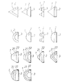
本発明の吸音構造体は、図1および図2に示した基本的な断面形状のほかに、図3に示すように、2層の金属多孔質材1、2および3層の金属多孔質材1、21、22の形状や配置を様々に変化させることもできる。また図4に示すように断面が三角形や半円状とすることもできる。更に図5に示すように円形の断面形状とすることもできる。この図5の場合にはどの方向からの音に対しても吸音効果が期待できるという利点がある。また、本発明では、図示しないが、4層の金属多孔質材に具体化できるのはもちろんである。
なお、本発明の吸音構造体は、その吸音特性を大幅に損なわない範囲において、表面や空気層部に孔開き板や網等の透孔を有する材料やフィルムを配置したり、空気層部に繊維状物や粒状物等の連通孔を有する多孔質材を挿入・充填してもよい。
【0020】
次に、本発明の吸音板について述べる。
本発明の吸音板は、図6に例示するように、上記したいずれかの吸音構造体を、枠材6との内部に組み付けてパネル化したものである。図6では、金属金属多孔質材1、2および遮音材3を枠材6に組み付けた例であるが、枠材6の材質としては、金属、セメント、プラスチック等の従来と同様の材質を採用することができる。
【0021】
なお、図6の吸音板をトンネル、堀割の壁面、天井面や高架の裏面に設置する場合は、壁面がコンクリート等の遮音材であるので遮音材が重複することになるが、この場合は、吸音板の方の遮音材を省略してもよい。一方、図6のように遮音材3付きの吸音板は吸音性遮音板として防音壁に使用することができる。この場合はH型支柱間に落とし込んで防音壁等を構成する。トンネル、堀割の壁面、天井面にはコンクリート壁面にアンカーボルトを所定の間隔で打設し、取り付け金具を用いて固定する方法などにより取り付ける。高架裏面へは受け梁などの下地にボルトで固定する方法などにより取り付けられる。
【0022】
【実施例】
繊維径20〜200μm、繊維長10mm以上のアルミニウム繊維を集合させたマット状の金属繊維体と、アルミニウム製エキスパンドメタルと、アルミニウム製パンチングメタルとをアクリル樹脂系の接着剤を用いて、表1に示す各種の物性を持つ、表面寸法が500×2000mmの平板状の多孔質材を作成した。
表中のA〜D、F〜Iは所定の面密度となるように繊維量を調整し、積層したマット状のアルミニウム繊維体を調製し、その片面又は両面にアルミニウム製エキスパンドメタル、パンチングメタルを配置して、ロール圧延成形することによって多孔質材を作成した。Gはロール圧延成形後、アクリル樹脂系の接着剤を空隙を目詰まりさせないように内部まで含浸した後、硬化して作成した。
Eは所定の面密度のマット状のアルミニウム繊維体をそのままロール圧延成形したのち、アクリル樹脂を系の接着剤を空隙を目詰まりさせないように内部まで含浸した後、硬化して作成した。
【0023】
このようにして得られた各種の多孔質材を、表2に示す条件に配置して吸音構造体を作成し、各吸音構造体について、パルス音源を用い試験体に垂直に入射させて吸音率を測定する方法により測定した。この表には、周波数400〜4000Hzにおける算術平均吸音率を求めて記載した。なお、遮音材は亜鉛鉄板とし、各試験体共通とした。
また、試験体No4、No14、No21、No24については、周波数100〜4000Hzにおける周波数−吸音率の特性を図7に示した。
なお、表中、試験体No1〜No20は、本発明の実施例であり、試験体No21〜No26は、本発明の技術的範囲に含まれない比較例である。
【0024】
この結果によれば、本発明の試験体No1〜12は、幅広い周波数にわたって高い吸音率を示し、かつ400〜4000Hzの平均吸音率も高い値を示すことが分かる。また、多孔質材を1枚だけ配置した試験体No25〜26の吸音特性には、特定の周波数域の吸音率が高くなるというピーク性があり、400〜4000Hzの平均吸音率も本発明のNo1〜20の場合より低い。なお、本発明の範囲外の試験体No21〜23の吸音特性にも吸音特性にピーク性があり、400〜4000Hzの平均吸音率も本発明のNo1〜20の場合より低いことも理解できる。
【0025】
【表1】

【0026】
【表2】
空間(1) は、多孔質材(1) と多孔質材(2) との間の空間、空間(2) は、多孔質材(2) と多孔質材(3) との間の空間を示す。
【0027】
【発明の効果】
以上に説明したように、本発明の吸音構造体及び吸音板は、表面側と中間部分と裏面側のアルミニウム系の金属多孔質材の面密度を前述のように変化させて配置することにより、幅広い周波数領域にわたって高い吸音性能を発揮でき、また長期間にわたり安定した吸音性能を維持することができる利点がある。
【図面の簡単な説明】
【図1】本発明の吸音構造体を示す模式的な断面図。
【図2】本発明の吸音構造体の他の構造を示す模式的な断面図。
【図3】吸音構造体の変形例を示す断面図。
【図4】吸音構造体の他の変形例を示す断面図。
【図5】吸音構造体の他の変形例を示す断面図。
【図6】本発明の吸音板を示す斜視図(A)及び断面図(B)。
【図7】実施例の吸音特性図。
【符号の説明】
1、2、21、22 金属多孔質材、3 遮音材、4、41、42 中間空気層、5 背後空気層、6 枠材、7 支柱。[0001]
BACKGROUND OF THE INVENTION
The present invention relates to a sound absorbing structure used for noise countermeasures such as a noise barrier for roads and railways and a tunnel moat, and a sound absorbing plate using the sound absorbing structure.
[0002]
[Prior art]
As a sound absorbing material used for noise countermeasures such as soundproof walls and tunnel moats, flat porous sound absorbing materials such as inorganic fiber sound absorbing material, metal fiber sound absorbing material, cement or calcium silicate foam sound absorbing material, ceramic sound absorbing material, etc. Is used. However, since these have a constant composition, porosity, air flow resistance, strength, etc., their sound absorption performance is also constant, and it is difficult to improve the sound absorption performance by changing the void structure and the like. In particular, rigid porous sound-absorbing materials such as metal fiber-based sound-absorbing materials are difficult to improve because of their peak sound absorption characteristics.
[0003]
[Problems to be solved by the invention]
The present invention has been made to solve the above-described conventional problems and provide a sound absorbing structure having a high sound absorbing performance over a wide frequency range and a sound absorbing plate using the sound absorbing structure.
[0004]
[Means for Solving the Problems]
The above problem is that the sound-absorbing structure of the present invention has three or more layers of an aluminum-based metal porous material arranged with an intermediate air layer between them, and a sound insulating material with a back air layer behind it. The sound absorbing structure is arranged, and the surface density of the metal porous material in the last row is larger than the surface density of the metal porous material in the front row in a ratio range of 1.1 to 10 , and is intermediate The surface density of the porous metal material arranged in the above is equal to or greater than the surface density of the metal porous material in the front row, and is smaller than the surface density of the metal porous material in the last row. This can be solved by a sound absorbing structure.
[0005]
Further, the metal porous material can be embodied in a form that is a porous material made of an aluminum-based metal fiber body, or in a form that is a porous material in which an aluminum-based metal fiber body and a metal perforating material are laminated. Furthermore, it is preferable that the surface density of the aluminum-based metal fiber body is 0.3 to 5.0 kg / m 2 .
In addition to the above, the metal porous material can also be applied to a porous material in which aluminum-based metal particles are bonded, and a porous material made of an aluminum-based metal foam. A combination of two or more of these can also be applied.
[0006]
Furthermore, the above problem can be solved by the sound absorbing plate, wherein the sound absorbing structure of the various configurations Ward described previously, metal, that it has been assembled from cement or plastic frame member.
[0007]
The sound-absorbing structure of the present invention can exhibit high sound-absorbing performance over a wide frequency range by combining aluminum-based metal porous materials having different surface densities through a space. The reason is that sound absorption characteristics having peaks at different frequencies can be obtained by changing the thickness of the air layer behind the thin plate-like porous material, but the sound absorbing structure of the present invention is located at different positions from the sound insulating material. Since the metal porous materials are respectively arranged on the two, peaks appear at different frequencies, and the sound absorption characteristics as a whole are flattened. In addition, since the surface density of the front and rear metal porous materials is changed, there is an advantage that the sound absorption characteristics are further flattened as shown in the data of examples described later. Moreover, since the aluminum type metal porous material is used, it is excellent in weather resistance and corrosion resistance, and the sound absorption performance is not deteriorated over a long period of time.
[0008]
DETAILED DESCRIPTION OF THE INVENTION
Hereinafter, preferred embodiments of the present invention will be described with reference to the drawings.
FIG. 1 is a schematic cross-sectional view showing a first embodiment of a sound absorbing structure according to the present invention, wherein 1 is a metal porous material in the front-side front row, and 2 is a metal porous in the back row arranged inside. The
In the present invention, these metal
[0009]
When the surface density is changed in this way, the sound absorption coefficient peaks of the respective porous materials appear at different frequencies, the overall sound absorption characteristics are flattened, and high sound absorption characteristics can be obtained over a wide range of frequencies. Contrary to the present invention, when the surface density of the first row of
[0010]
In the case of FIG. 1 above, the metal
In this case, the surface density of the metal
In this case as well, the sound insulating
[0011]
The size of the sound absorbing structure of the present invention is as follows.
First, the thickness of the entire sound absorbing structure is adjusted according to the frequency of the target sound source, but is set to about 50 to 200 mm in consideration of application to a general soundproof wall. When the target is low frequency sound, the entire thickness is increased, and when the target is high frequency sound, the entire thickness is decreased. It is preferable that the metal
[0012]
In the first embodiment, the metal
[0013]
In order to further increase the strength of such a metal fiber body, it is combined with a metal perforated material such as punching metal, metal net, and expanded metal having an opening ratio of 20 to 90% and a thickness of about 0.4 to 1 mm, It is preferable to protect the surface of one side or both sides. The metal perforated material as the protective material is also preferably an aluminum-based metal.
[0014]
In the present invention, the reason for limiting the numerical values is as follows. When the fiber diameter and the fiber length are smaller than the above values, the mechanical strength of the metal
Further, if the aperture ratio of the metal perforated material is smaller than the above value, the sound absorbing performance is lowered, and conversely if it is larger than the above value, the mechanical strength of the metal
[0015]
In the second embodiment of the present invention, the metal
[0016]
In the third embodiment, the metal
[0017]
In the first to third embodiments, one kind of material that can be used for each of the metal porous materials is exemplified. However, as described in claim 8, the aluminum-based metal fibers described above are used. Or a combination of two or more selected from the group of an aluminum-based metal particle bonded body and an aluminum-based metal foam.
[0018]
In the present invention, as the
[0019]
In addition to the basic cross-sectional shape shown in FIGS. 1 and 2, the sound-absorbing structure of the present invention includes two layers of
In the sound absorbing structure of the present invention, a material or a film having a through hole such as a perforated plate or a net is disposed on the surface or the air layer portion within a range not significantly impairing the sound absorbing characteristics, or the air layer portion is disposed on the air layer portion. A porous material having a communicating hole such as a fibrous material or a granular material may be inserted and filled.
[0020]
Next, the sound absorbing plate of the present invention will be described.
As illustrated in FIG. 6, the sound absorbing plate of the present invention is a panel formed by assembling any of the above sound absorbing structures inside the
[0021]
In addition, when installing the sound absorbing plate in FIG. 6 on the tunnel, the wall surface of the moat, the ceiling surface, or the back surface of the elevated, the sound insulating material overlaps because the wall surface is a sound insulating material such as concrete. The sound insulating material toward the sound absorbing plate may be omitted. On the other hand, the sound absorbing plate with the
[0022]
【Example】
A mat-shaped metal fiber body in which aluminum fibers having a fiber diameter of 20 to 200 μm and a fiber length of 10 mm or more are assembled, an aluminum expanded metal, and an aluminum punching metal are used in Table 1, using an acrylic resin adhesive. A flat plate-shaped porous material having a surface size of 500 × 2000 mm having various physical properties shown was prepared.
A to D and F to I in the table adjust the fiber amount so as to have a predetermined areal density, prepare a laminated mat-like aluminum fiber body, and apply aluminum expanded metal and punching metal on one or both sides thereof. A porous material was created by placing and roll rolling. G was prepared by roll rolling and then impregnating an acrylic resin adhesive to the inside so as not to clog the voids, and then curing.
E was prepared by roll-rolling a mat-like aluminum fiber body having a predetermined surface density as it was, then impregnating an acrylic resin with an adhesive to the inside so as not to clog the voids, and then curing.
[0023]
The various porous materials obtained in this manner are arranged under the conditions shown in Table 2 to create sound absorbing structures, and each sound absorbing structure is made to enter the test body perpendicularly using a pulsed sound source to absorb the sound absorption rate. It measured by the method of measuring. In this table, the arithmetic average sound absorption coefficient at a frequency of 400 to 4000 Hz was obtained and described. The sound insulating material was a galvanized iron plate, which was common to each test specimen.
Moreover, about test body No4, No14, No21, No24, the characteristic of the frequency-sound absorption rate in the frequency of 100-4000 Hz was shown in FIG.
In the table, test bodies No1 to No20 are examples of the present invention, and test bodies No21 to No26 are comparative examples not included in the technical scope of the present invention.
[0024]
According to this result, it turns out that test body No1-12 of this invention shows a high sound absorption coefficient over a wide frequency, and also shows a high value for the average sound absorption coefficient of 400-4000 Hz. In addition, the sound absorption characteristics of the specimens Nos. 25 to 26 in which only one porous material is arranged have a peak property that the sound absorption coefficient in a specific frequency range is high, and the average sound absorption coefficient of 400 to 4000 Hz is also No. 1 of the present invention. Lower than ~ 20. In addition, it can also be understood that the sound absorption characteristics of the test bodies No. 21 to No. 23 outside the scope of the present invention also have a peak sound absorption characteristic, and the average sound absorption rate of 400 to 4000 Hz is lower than that of Nos. 1 to 20 of the present invention.
[0025]
[Table 1]
[0026]
[Table 2]
Space (1) is the space between porous material (1) and porous material (2), and space (2) is the space between porous material (2) and porous material (3). Show.
[0027]
【The invention's effect】
As described above, the sound absorbing structure and the sound absorbing plate of the present invention are arranged by changing the surface density of the aluminum-based metal porous material on the front surface side, the intermediate portion, and the back surface side as described above, There is an advantage that high sound absorption performance can be exhibited over a wide frequency range, and stable sound absorption performance can be maintained over a long period of time.
[Brief description of the drawings]
FIG. 1 is a schematic cross-sectional view showing a sound absorbing structure of the present invention.
FIG. 2 is a schematic cross-sectional view showing another structure of the sound absorbing structure of the present invention.
FIG. 3 is a cross-sectional view showing a modification of the sound absorbing structure.
FIG. 4 is a cross-sectional view showing another modification of the sound absorbing structure.
FIG. 5 is a cross-sectional view showing another modification of the sound absorbing structure.
FIG. 6 is a perspective view (A) and a cross-sectional view (B) showing a sound absorbing plate of the present invention.
FIG. 7 is a sound absorption characteristic diagram of the example.
[Explanation of symbols]
1, 2, 21, 22 Metal porous material, 3 Sound insulation material, 4, 41, 42 Intermediate air layer, 5 Back air layer, 6 Frame material, 7 Prop.
Claims (8)
Priority Applications (1)
| Application Number | Priority Date | Filing Date | Title |
|---|---|---|---|
| JP17854499A JP3932156B2 (en) | 1999-01-19 | 1999-06-24 | Sound absorbing structure and sound absorbing plate |
Applications Claiming Priority (3)
| Application Number | Priority Date | Filing Date | Title |
|---|---|---|---|
| JP998399 | 1999-01-19 | ||
| JP11-9983 | 1999-01-19 | ||
| JP17854499A JP3932156B2 (en) | 1999-01-19 | 1999-06-24 | Sound absorbing structure and sound absorbing plate |
Publications (2)
| Publication Number | Publication Date |
|---|---|
| JP2000276178A JP2000276178A (en) | 2000-10-06 |
| JP3932156B2 true JP3932156B2 (en) | 2007-06-20 |
Family
ID=26344824
Family Applications (1)
| Application Number | Title | Priority Date | Filing Date |
|---|---|---|---|
| JP17854499A Expired - Fee Related JP3932156B2 (en) | 1999-01-19 | 1999-06-24 | Sound absorbing structure and sound absorbing plate |
Country Status (1)
| Country | Link |
|---|---|
| JP (1) | JP3932156B2 (en) |
Families Citing this family (10)
| Publication number | Priority date | Publication date | Assignee | Title |
|---|---|---|---|---|
| JP2003295867A (en) * | 2002-02-01 | 2003-10-15 | Ngk Insulators Ltd | Sound absorption structure |
| US20070272482A1 (en) * | 2004-04-30 | 2007-11-29 | Kabushiki Kaisha Kobe Seiko Sho | Porous Sound Absorbing Structure |
| JP4567513B2 (en) * | 2004-04-30 | 2010-10-20 | 株式会社神戸製鋼所 | Porous sound absorbing structure |
| JP4514128B2 (en) * | 2004-10-07 | 2010-07-28 | 日本特殊塗料株式会社 | Movable indoor sound absorber |
| KR100919348B1 (en) | 2004-12-02 | 2009-09-25 | 가부시키가이샤 고베 세이코쇼 | Vehicle body panel structure |
| JP2012082631A (en) * | 2010-10-13 | 2012-04-26 | Japan Pile Corp | Soundproof panel |
| JP5244208B2 (en) * | 2011-04-12 | 2013-07-24 | 株式会社神戸製鋼所 | Double wall structure |
| CN105696763A (en) * | 2016-02-17 | 2016-06-22 | 江苏瑞赛恩建材实业有限公司 | High-strength sound absorption board |
| CN105672507A (en) * | 2016-02-17 | 2016-06-15 | 江苏瑞赛恩建材实业有限公司 | Environment-friendly sound absorbing board |
| CN109493842B (en) * | 2018-12-12 | 2023-12-29 | 东华大学 | Sound insulation and absorption cover for measuring fiber bundle stretch breaking acoustic emission, method and application |
-
1999
- 1999-06-24 JP JP17854499A patent/JP3932156B2/en not_active Expired - Fee Related
Also Published As
| Publication number | Publication date |
|---|---|
| JP2000276178A (en) | 2000-10-06 |
Similar Documents
| Publication | Publication Date | Title |
|---|---|---|
| EP0697051B1 (en) | False ceiling | |
| US6675551B1 (en) | Plate-shaped constructional element and method | |
| US10508828B2 (en) | Splitter and sound attenuator including the same | |
| JP3932156B2 (en) | Sound absorbing structure and sound absorbing plate | |
| JP2006511830A (en) | Ultralight trim composite | |
| CN102926476A (en) | Sound insulation board | |
| JP2001003322A (en) | Sound absorbing structure | |
| Hongisto et al. | Sound insulation of double walls–An experimental parametric study | |
| CN106223222A (en) | Acoustic barrier unit board based on broadband porous plate acoustic adsorption device and method for designing thereof | |
| JP2002215172A (en) | Acoustic material an acoustic structure | |
| JP3583644B2 (en) | Soundproofing material | |
| JP2003295867A (en) | Sound absorption structure | |
| WO2007073732A2 (en) | Multi-layered porous sound-absorber | |
| JPH0325108A (en) | Sound absorbing wall structure | |
| JP2006316467A (en) | Sound insulating double wall structure | |
| JPH10331286A (en) | Composite sound absorbing panel | |
| JP2004037582A (en) | Sound absorbing structure | |
| EP3935624B1 (en) | Sound absorber, structure and use of a sound absorber | |
| JP5320002B2 (en) | Storage structure for composite sound absorbing structure and composite sound absorbing structure disposed in the storage structure | |
| JP3957128B2 (en) | Sound absorption mechanism | |
| JPH04266942A (en) | Porous material and sound-absorbing panel | |
| JP2793570B2 (en) | Ceramic sound absorbing material | |
| DE202015004064U1 (en) | Device for reducing sound pressure levels | |
| WO2018179485A1 (en) | Soundproof panel | |
| JPH04333897A (en) | Sound absorbing panel |
Legal Events
| Date | Code | Title | Description |
|---|---|---|---|
| A621 | Written request for application examination |
Free format text: JAPANESE INTERMEDIATE CODE: A621 Effective date: 20050119 |
|
| A977 | Report on retrieval |
Free format text: JAPANESE INTERMEDIATE CODE: A971007 Effective date: 20050905 |
|
| A131 | Notification of reasons for refusal |
Free format text: JAPANESE INTERMEDIATE CODE: A131 Effective date: 20060714 |
|
| A521 | Written amendment |
Free format text: JAPANESE INTERMEDIATE CODE: A523 Effective date: 20060906 |
|
| TRDD | Decision of grant or rejection written | ||
| A01 | Written decision to grant a patent or to grant a registration (utility model) |
Free format text: JAPANESE INTERMEDIATE CODE: A01 Effective date: 20070309 |
|
| A61 | First payment of annual fees (during grant procedure) |
Free format text: JAPANESE INTERMEDIATE CODE: A61 Effective date: 20070309 |
|
| R150 | Certificate of patent or registration of utility model |
Ref document number: 3932156 Country of ref document: JP Free format text: JAPANESE INTERMEDIATE CODE: R150 Free format text: JAPANESE INTERMEDIATE CODE: R150 |
|
| S111 | Request for change of ownership or part of ownership |
Free format text: JAPANESE INTERMEDIATE CODE: R313113 |
|
| R350 | Written notification of registration of transfer |
Free format text: JAPANESE INTERMEDIATE CODE: R350 |
|
| FPAY | Renewal fee payment (event date is renewal date of database) |
Free format text: PAYMENT UNTIL: 20100323 Year of fee payment: 3 |
|
| FPAY | Renewal fee payment (event date is renewal date of database) |
Free format text: PAYMENT UNTIL: 20130323 Year of fee payment: 6 |
|
| R250 | Receipt of annual fees |
Free format text: JAPANESE INTERMEDIATE CODE: R250 |
|
| FPAY | Renewal fee payment (event date is renewal date of database) |
Free format text: PAYMENT UNTIL: 20130323 Year of fee payment: 6 |
|
| FPAY | Renewal fee payment (event date is renewal date of database) |
Free format text: PAYMENT UNTIL: 20140323 Year of fee payment: 7 |
|
| R250 | Receipt of annual fees |
Free format text: JAPANESE INTERMEDIATE CODE: R250 |
|
| R250 | Receipt of annual fees |
Free format text: JAPANESE INTERMEDIATE CODE: R250 |
|
| R250 | Receipt of annual fees |
Free format text: JAPANESE INTERMEDIATE CODE: R250 |
|
| R250 | Receipt of annual fees |
Free format text: JAPANESE INTERMEDIATE CODE: R250 |
|
| R250 | Receipt of annual fees |
Free format text: JAPANESE INTERMEDIATE CODE: R250 |
|
| R250 | Receipt of annual fees |
Free format text: JAPANESE INTERMEDIATE CODE: R250 |
|
| LAPS | Cancellation because of no payment of annual fees |