JP3921208B2 - Tube connection structure - Google Patents
Tube connection structure Download PDFInfo
- Publication number
- JP3921208B2 JP3921208B2 JP2004160335A JP2004160335A JP3921208B2 JP 3921208 B2 JP3921208 B2 JP 3921208B2 JP 2004160335 A JP2004160335 A JP 2004160335A JP 2004160335 A JP2004160335 A JP 2004160335A JP 3921208 B2 JP3921208 B2 JP 3921208B2
- Authority
- JP
- Japan
- Prior art keywords
- tube
- pressure
- working fluid
- fluid chamber
- housing member
- Prior art date
- Legal status (The legal status is an assumption and is not a legal conclusion. Google has not performed a legal analysis and makes no representation as to the accuracy of the status listed.)
- Expired - Fee Related
Links
Images


Landscapes
- Joints With Pressure Members (AREA)
- Joints With Sleeves (AREA)
- Sealing Devices (AREA)
Description
本発明は、工場等における配管に用いられる管体の接続構造に係り、特に、管体の連結部における密封性を確保することができるようにされた接続構造に係るものである。 The present invention relates to a connecting structure for tubular bodies used for piping in factories and the like, and more particularly, to a connecting structure that can ensure sealing performance at a connecting portion of tubular bodies.
化学プラントやその他の多くの工場において、流体の性状を有する原料や生成体の他、媒体や動力源など、各種の流体を流通させる流路を形成するために配管構造体が利用されている。このような配管構造体は、製造上や施工上、或いは管理上の理由によって所定長さの管体を複数本連結することにより、所望の流路を構成している。即ち、それら複数の管体の両開口端部を互いに突き合わせて固定することで接続し、全体として連通させることで、目的とする長さや流路形態を実現せしめた構造とされている。 In chemical plants and many other factories, piping structures are used to form flow paths through which various fluids such as media and power sources, as well as raw materials and products having fluid properties, are circulated. Such a piping structure forms a desired flow path by connecting a plurality of pipes having a predetermined length for manufacturing, construction, or management reasons. That is, it is set as the structure which implement | achieved the target length and flow path form by connecting both the opening edge parts of these several pipe bodies by mutually abutting and fixing, and making it connect as a whole.
ところで、このような配管構造では、各管体の連結部において、高度で且つ安定した流体密性が要求される場合が多い。そのため、管体の連結部には、従来から、流体密性を確保するためのシール構造が採用されている。 By the way, in such a piping structure, high and stable fluid tightness is often required at the connecting portion of each tubular body. Therefore, conventionally, a sealing structure for ensuring fluid tightness has been adopted for the connecting portion of the tube body.
そのようなシール構造としては、例えば、実開昭55−57587号公報(特許文献1)や実開昭63−84489号公報(特許文献2)に記載されているように、各管体の開口端部にそれぞれフランジを形成し、各管体の開口端部を突き合わせてフランジ間を複数本の締付ボルトで締め付けて接続固定するに際して、それらのフランジの重ね合わせ面間に環状パッキンを挟み込んで挟圧したものが知られている。 As such a seal structure, for example, as described in Japanese Utility Model Laid-Open No. 55-57587 (Patent Document 1) and Japanese Utility Model Laid-Open No. 63-84489 (Patent Document 2), the opening of each pipe body is disclosed. When flanges are formed at the ends, the open ends of each tube are butted together and the flanges are tightened with a plurality of fastening bolts to secure the connection, an annular packing is sandwiched between the overlapping surfaces of the flanges. What is pinched is known.
しかしながら、このような管体の接続部におけるシール構造では、安定した流体密性を確保することが難しい。蓋し、環状パッキンに挟圧力を及ぼす、周上複数本のボルトの締付力を全て同一に設定保持することが難しく、締付力が不均一となって環状パッキンへの挟圧力が偏荷重となり易い。そのような偏荷重が発生すると、周上の特定の部位で、パッキンの挟圧力が不足したり、反対に過大となってしまい、その結果、パッキンに隙間や亀裂が発生し易く、そこから流体が漏出するおそれがあるという問題があった。 However, it is difficult to ensure stable fluid tightness with such a sealing structure at the connecting portion of the tube. It is difficult to set the same tightening force for the multiple bolts on the circumference that apply the clamping pressure to the annular packing, and the clamping force becomes uneven and the clamping pressure on the annular packing is unbalanced. It is easy to become. When such an unbalanced load occurs, the clamping pressure of the packing is insufficient at a specific part on the circumference or, on the contrary, the packing is excessively large. There was a problem that could leak.
しかも、偏荷重の発生を外部から確認することが極めて困難であることから、保守や点検が難しく面倒であり、流体の漏出を事前に予測することは勿論、それを防止することも困難であったのである。 In addition, since it is extremely difficult to confirm the occurrence of an unbalanced load from the outside, maintenance and inspection are difficult and troublesome, and it is difficult to predict fluid leakage in advance and to prevent it. It was.
なお、例えば原子核変換に関する技術分野などで用いられる流路のように、極めて高度なシール性能が要求される管体の接続構造としては、特開平8−200583号公報(特許文献3)に開示されている如き高度なシール機構も提案されている。しかしながら、このような高度なシール機構は構造が複雑になって、コストの増大や施工及び管理に手間がかかるといった問題があり、一般の多くの工場の配管などに採用することは現実的ではない。 Note that, for example, a pipe connection structure that requires extremely high sealing performance, such as a flow path used in the technical field related to nuclear transmutation, is disclosed in JP-A-8-200543 (Patent Document 3). Advanced sealing mechanisms are also proposed. However, such an advanced sealing mechanism has a complicated structure, and there is a problem that the cost is increased and construction and management are troublesome. Therefore, it is not practical to employ it for piping in many general factories. .
また、特に食品工場等では、衛生上の理由から毎日のように頻繁に管体の分解と洗浄,再接続が実施される。更に、強酸性や強アルカリ性の流体を搬送する配管においても、頻繁な点検や交換の作業が実施される。このような場合において、簡易な構造と容易な施工性能をもって、高度なシール性能を安定して得ることのできるシール機構をもった管体の接続構造が切望されていたのである。 Particularly in food factories and the like, pipes are frequently disassembled, cleaned and reconnected on a daily basis for reasons of hygiene. Furthermore, frequent inspection and replacement work is also performed on piping that transports strongly acidic or strongly alkaline fluids. In such a case, a tube connecting structure having a sealing mechanism capable of stably obtaining a high degree of sealing performance with a simple structure and easy construction performance has been desired.
ここにおいて、本発明は、上述の如き事情を背景として為されたものであって、その解決課題とするところは、高度なシール性能を安定して得ることが出来るシール機構をもった管体の接続構造を、簡易な構造と優れた施工性能をもって実現することにある。 Here, the present invention has been made in the background as described above, and the problem to be solved is that of a tubular body having a sealing mechanism capable of stably obtaining a high degree of sealing performance. The purpose is to realize a connection structure with a simple structure and excellent construction performance.
以下このような課題を解決するために為された本発明の態様を記載する。なお、以下に記載の各態様において採用される構成要素は、可能な限り任意な組み合わせで採用可能である。また、本発明の態様乃至は技術的特徴は、以下に記載のものに限定されることなく、明細書全体および図面に記載されたもの、或いはそれらの記載から当業者が把握することの出来る発明思想に基づいて認識されるものであることが理解されるべきである。 Hereinafter, embodiments of the present invention made to solve such problems will be described. In addition, the component employ | adopted in each aspect as described below is employable by arbitrary combinations as much as possible. Further, aspects or technical features of the present invention are not limited to those described below, but are described in the entire specification and drawings, or an invention that can be understood by those skilled in the art from those descriptions. It should be understood that it is recognized based on thought.
すなわち、本発明の第一の態様は、二本の管体における各一方の開口端部を突き合わせ状態で相互に流体密に接続して連通せしめる管体の接続構造において、前記二本の管体の前記各一方の開口端部を互いに固定的に連結する連結手段を設ける一方、それら各一方の開口端部の突き合わせ部分の外周面に重ね合わせられるようにして外挿状態で配設される環状のシール部材を設けると共に、該シール部材の外周側を全周に亘って覆う環状のハウジング部材を設けて、該ハウジング部材と該シール部材の間に周方向で実質的に連続した作用流体室を形成し、該作用流体室に対して外部から圧力流体を給排することの出来る給排手段を設けて、該作用流体室に圧力流体を充填せしめて該シール部材に対して外周面から圧力を及ぼすことにより、該シール部材を該二本の管体の該各一方の開口端部の突き合わせ部分に対して外周面から密着させてシールするようにして、更に、該ハウジング部材の軸方向両端部分には、該二本の管体の各開口端部に設けた管体側取付片に対して連結ボルトで着脱可能に固定される継手側取付片を、周上の複数箇所に設けることにより、互いに接続されるそれら二本の管体を該ハウジング部材を利用して相互に連結したことを、特徴とする。
That is, according to a first aspect of the present invention, there is provided a pipe connection structure in which one open end portion of two pipes is connected in fluid communication with each other in a butted state, and the two pipes are connected. A connecting means for fixedly connecting the respective one open end portions to each other, while being arranged in an extrapolated state so as to be superposed on the outer peripheral surface of the butted portion of each one open end portion And an annular housing member that covers the entire outer periphery of the seal member, and a working fluid chamber that is substantially continuous in the circumferential direction is provided between the housing member and the seal member. Forming and supplying / discharging the working fluid chamber with pressure fluid from the outside, filling the working fluid chamber with the pressure fluid and applying pressure from the outer peripheral surface to the seal member. By exerting The seal member so as to seal by contact from the outer peripheral surface against the abutting portion of each of the one open end of the two of the tube, further, the axial end portion of said housing member, said Those joints that are connected to each other by providing joint-side attachment pieces that are detachably fixed with connecting bolts to the tube-side attachment pieces provided at the respective opening ends of the two pipe bodies. that the two of the tube were connected to each other by utilizing the housing member, and wherein.
このような第一の態様に従う構造とされた管体の接続構造においては、作用流体室に作用せしめられる正圧が、管体の連結部に外挿状態で配設したシール部材に対して外周面から押圧力として作用せしめられる。ここにおいて、作用流体室は実質的に周方向に連続していることから、シール部材の周方向の全周に亘って均一の押圧力が内周側に向けて作用せしめられることとなる。それ故、突き合わせられた管体の端部間に跨がって外挿状態で装着されたシール部材が、管体の連結部の外周面から密着されて、管体の端部間を全周に亘ってシールして、管体内を流通せしめられる流体の漏出を効果的に防ぐことが出来るのである。 In the tube connecting structure structured according to the first aspect as described above, the positive pressure applied to the working fluid chamber is the outer periphery of the sealing member disposed in an extrapolated state at the connecting portion of the tube. It acts as a pressing force from the surface. Here, since the working fluid chamber is substantially continuous in the circumferential direction, a uniform pressing force is applied toward the inner circumferential side over the entire circumference in the circumferential direction of the seal member. Therefore, the sealing member mounted in an extrapolated state straddling between the end portions of the butted tube bodies is closely attached from the outer peripheral surface of the connecting portion of the tube body, and the entire periphery between the end portions of the tube body is provided. It is possible to effectively prevent leakage of the fluid that can be circulated through the pipe body.
特に、本態様の管体接続構造においては、シール部材を管体の連結部に対して外周面から密着させる押圧力が、周方向の全周に亘って均等に作用せしめられ得ることから、偏った荷重がシール部材にかかることに起因するシール部位の局部的な隙間やシール部材の局部的な損傷を有利に防ぐことが出来るのであり、より確実なシール性能を高い信頼性と耐久性のもとに得ることが可能となる。
また、本態様に従う構造とされた管体の接続構造においては、ハウジング部材の取付けによって、二つの管体を接続することができることから、管体同士を別途、ボルトや溶接によって互いに固定する必要がない。それ故、構造の簡略化や部品点数の現象およびそれに伴う施工の作業効率の向上や低コスト化が実現可能となる。
In particular, in the tubular body connection structure of this aspect, the pressing force that causes the seal member to be in close contact with the coupling portion of the tubular body from the outer peripheral surface can be applied evenly over the entire circumference in the circumferential direction. It is possible to advantageously prevent local gaps in the seal part and local damage to the seal member due to the applied load on the seal member, and more reliable sealing performance with high reliability and durability. Can be obtained.
Moreover, in the connection structure of the pipe body made into the structure according to this aspect, since two pipe bodies can be connected by attachment of a housing member, it is necessary to fix pipe bodies mutually with a volt | bolt or welding. Absent. Therefore, simplification of the structure, the phenomenon of the number of parts, and improvement of work efficiency and cost reduction associated therewith can be realized.
更に、外部に給排手段を設けて、作用流体室に対する圧力流体の給排を可能としたことにより、管体を連結して接続構造を実質的に完成させた後に、作用流体室に圧力流体を供給したり、また、作用流体室から圧力流体を排出した後に接続構造を解除して管体の連結部位を分解したりすることが可能とされる。これにより、接続状態下での管体の突き合わせ部位におけるシール性能を十分に確保しつつ、管体の接続や分離の作業を容易に行うことが可能とされる。 Further, by providing an external supply and discharge means to enable supply and discharge of the pressure fluid to and from the working fluid chamber, the connection structure is substantially completed by connecting the tubes, and then the pressure fluid is placed in the working fluid chamber. In addition, after discharging the pressure fluid from the working fluid chamber, the connection structure can be released to disassemble the connecting portion of the tube body. Thereby, it is possible to easily connect and separate the pipes while ensuring sufficient sealing performance at the butted portions of the pipes in the connected state.
なお、本態様においては、二本の管体を接続した後、給排手段を遮断状態として、作用流体室に圧力流体を密閉することにより所定圧力を保持するようにしても良い。或いは、本発明においては、二本の管体の接続構造をそのままにして、給排手段を通じて外部から圧力流体を作用流体室に給排することで、作用流体室の圧力を適宜に調節可能としても良い。 In this aspect, after connecting the two pipe bodies, the supply / exhaust means may be shut off, and the pressure fluid may be sealed in the working fluid chamber to maintain a predetermined pressure. Alternatively, in the present invention, the pressure of the working fluid chamber can be appropriately adjusted by supplying and discharging pressure fluid from the outside to the working fluid chamber through the supply / discharge means while leaving the connection structure of the two pipes as they are. Also good.
また、本態様において、作用流体室に給排する圧力流体としては、気体でも液体でも良い。気体の場合には、例えば空気や不活性ガス等を適宜に採用することが可能であり、液体を採用する場合に比して設備が簡易で取扱いや保守等も容易に行うことが出来る。一方、液体の場合には、例えば水や不凍液、油などを適宜に採用することが可能であり、気体を採用する場合に比して大きな圧力を作用させ易い。 In this embodiment, the pressure fluid supplied to and discharged from the working fluid chamber may be gas or liquid. In the case of gas, for example, air, inert gas, or the like can be appropriately employed, and the equipment is simple and handling and maintenance can be easily performed as compared with the case of employing liquid. On the other hand, in the case of a liquid, for example, water, antifreeze liquid, oil, or the like can be appropriately employed, and a large pressure is easily applied as compared with the case of employing a gas.
本発明の第二の態様は、前記第一の態様に従う構造とされた管体の接続構造において、前記ハウジング部材の内周側にゴム弾性体からなる環状の中空チューブを収容状態で組み付けて、該中空チューブを、前記二本の管体の該各一方の開口端部の突き合わせ部分に対して外挿装着することにより、該中空チューブの内部空間によって前記作用流体室を形成したことを、特徴とする。 According to a second aspect of the present invention, in the tubular body connection structure configured according to the first aspect, an annular hollow tube made of a rubber elastic body is assembled to the inner peripheral side of the housing member in an accommodated state. The working fluid chamber is formed by the internal space of the hollow tube by extrapolating the hollow tube to the butted portion of the one open end of each of the two tubular bodies. And
このような、本態様に従う構造とされた管体の接続構造においては、中空チューブを用いて作用流体室を形成したことにより、作用流体室の流体密性を簡単な構造で容易に且つ高い信頼性をもって確保することが出来る。また、作用流体室において流体漏れ等の損傷があった場合などには、中空チューブだけを交換することで容易に且つ低コストに対処することができる。 In such a pipe connection structure configured according to this aspect, the working fluid chamber is formed using a hollow tube, so that the fluid tightness of the working fluid chamber can be easily and highly reliable with a simple structure. It can be secured with sex. Further, when there is damage such as fluid leakage in the working fluid chamber, it is possible to easily deal with low cost by replacing only the hollow tube.
本発明の第三の態様は、前記第二の態様に従う構造とされた管体の接続構造において、前記シール部材として筒形シート状のシール筒体を採用して、該シール筒体を前記管体に対して外挿すると共に、前記中空チューブを該シール筒体の外周面と前記ハウジング部材の内周面との間に配設したことを、特徴とする。
A third aspect of the present invention, prior Symbol connecting structure of the second in accordance with an aspect of the structure has been tube, employs the sealing member as a tubular sheet-like tubular sealing body, the sealing cylindrical body wherein It is characterized in that the hollow tube is disposed between the outer peripheral surface of the sealing cylinder and the inner peripheral surface of the housing member while being extrapolated with respect to the tubular body.
このような、本態様に従う構造とされた管体の接続構造においては、例えば、中空チューブの材料を、圧力流体に対する耐蝕性や伸縮性等を重視して選択する一方、シール筒体の材料を、管体内を流通せしめられる流体に対する耐蝕性や管体への押圧に対する耐久性等を重視して選択することが出来る。これにより、中空チューブとシール筒体を、それぞれ要求される性能に対して高度に対応した材料で形成することが可能となり、全体としてより高性能な管体接続構造が実用可能となる。 In such a pipe connection structure according to this embodiment, for example, the material of the hollow tube is selected with emphasis on the corrosion resistance, stretchability, etc. against the pressure fluid, while the material of the seal cylinder is selected. The selection can be made with an emphasis on the corrosion resistance to the fluid circulated in the tubular body and the durability against the pressure on the tubular body. As a result, the hollow tube and the seal cylinder can be formed from materials that are highly compatible with the required performance, and a higher-performance tube connection structure as a whole can be put into practical use.
本発明の第四の態様は、前記第一乃至第三の何れかの態様に従う構造とされた管体の接続構造であって、前記ハウジング部材の一部において管体に向かって内周側に開口する環状凹所を形成し、該環状凹所の開口部分に対して円筒形状の可動蓋部材を嵌め込んで配設することにより前記作用流体室を画成すると共に、該可動蓋部材によって前記シール部材を構成したことを、特徴とする。 According to a fourth aspect of the present invention, there is provided a connecting structure for a tubular body having a structure according to any one of the first to third aspects, and a part of the housing member is arranged on an inner peripheral side toward the tubular body. The working fluid chamber is defined by forming an annular recess to be opened and fitting and disposing a cylindrical movable lid member in the opening of the annular recess, and the movable lid member defines the working fluid chamber. The seal member is configured.
このような、本態様に従う構造とされた管体の接続構造においては、ハウジング部材を壁部の一部に利用して作用流体室を形成することが出来ることから、作用流体室を少ない部品点数で形成することが可能となり、構造の簡略化も実現可能となる。また、ハウジング部材を壁部の一部を利用して作用流体室を形成することにより、作用流体室の耐久性や信頼性をハウジング部材によって有利に確保することができる。更にまた、ハウジング部材に対して、別体形成された可動蓋部材を組み付けて作用流体室が形成されることから、採用する圧力流体や作用する圧力の大きさ等を考慮して、必要に応じて可動蓋部材だけを交換することも可能であり、各種条件に対して容易に対応することも出来る。 In such a pipe connection structure structured according to this aspect, the working fluid chamber can be formed by utilizing the housing member as a part of the wall portion, so that the number of parts of the working fluid chamber is small. Thus, the structure can be simplified. In addition, by forming the working fluid chamber by utilizing a part of the wall portion of the housing member, the durability and reliability of the working fluid chamber can be advantageously ensured by the housing member. Furthermore, since the working fluid chamber is formed by assembling the movable cover member formed separately from the housing member, the pressure fluid to be used, the magnitude of the acting pressure, etc. are taken into consideration as necessary. It is also possible to replace only the movable lid member, and it is possible to easily cope with various conditions.
本発明の第五の態様は、前記第四の態様に従う構造とされた管体の接続構造であって、前記可動蓋部材の軸方向両端部分において、それぞれ、外周側に向かって突出する環状シール片を形成したことを、特徴とする。
A fifth aspect of the present invention, there is provided a connecting structure of structure has been tube according to the fourth aspect, in the axial end portion of said movable cover member, respectively, the ring-shaped projecting toward the outer peripheral side that the formation of the sheet Lumpur piece, characterized.
このような本態様においては、作用流体室に圧力が及ぼされることによって、可動蓋部材の軸方向両端部分の環状シール片が軸方向外方に押し広げられて、ハウジング部材の内面に対して押し付けられることとなる。これにより、可動蓋部材の軸方向両端部分が、それぞれ、ハウジング部材の開口周縁部に対して、一層高い流体密性をもって密接され得て、作用流体室の流体密性ひいては作用流体室の圧力に基づいて管体の接続部位に押し付けられる可動蓋部材による当該接続部位の流体密性を、より高度に確保することが可能となる。
In this embodiment, when pressure is applied to the working fluid chamber, the annular seal pieces at both axial end portions of the movable lid member are expanded outward in the axial direction and pressed against the inner surface of the housing member. Will be. As a result, both end portions in the axial direction of the movable lid member can be brought into close contact with the peripheral edge of the opening of the housing member with higher fluid tightness, so that the fluid tightness of the working fluid chamber and thus the pressure of the working fluid chamber can be reduced. Based on this, it is possible to secure the fluid tightness of the connection portion by the movable lid member pressed against the connection portion of the tube body to a higher degree.
本発明の第六の態様は、前記第一乃至第五の何れかの態様に従う構造とされた管体の接続構造において、前記作用流体室の圧力を検出する圧力検出手段を設けたことを特徴とする。 According to a sixth aspect of the present invention, in the tube connection structure having the structure according to any one of the first to fifth aspects, a pressure detecting means for detecting the pressure of the working fluid chamber is provided. And
このような、本態様に従う構造とされた管体の接続構造においては、例えば、圧力検出手段による検出値を、常時或いは適当な時間毎に監視することにより、何等かの不具合の発生を速やかに検出して対処することも可能となる。また、作用流体室の圧力を、各種条件の変化等に応じて確認したり、検出値に基づいて圧力調節することも容易に可能となる。特に、本態様における圧力検出手段の検出信号を利用して、作用流体室への圧力流体の給排をコントロールする制御系を構成することにより、作用流体室の圧力を目的とする値に自動的に調節することも実現可能となる。 In such a tube connection structure configured according to this aspect, for example, by monitoring the detection value by the pressure detection means at all times or every appropriate time, the occurrence of any malfunction can be promptly performed. It is also possible to detect and deal with it. In addition, it is possible to easily check the pressure of the working fluid chamber according to changes in various conditions and adjust the pressure based on the detected value. In particular, by using the detection signal of the pressure detection means in this aspect to configure a control system that controls the supply and discharge of the pressure fluid to and from the working fluid chamber, the pressure of the working fluid chamber is automatically set to the target value. It is also possible to adjust to.
本発明の第七の態様は、前記第一乃至第六の何れかの態様に従う構造とされた管体の接続構造であって、前記二つの管体において、互いに接続される各開口端部の何れもが管体の本体部分の形状のままの切り放し状態とされていることを、特徴とする。
According to a seventh aspect of the present invention, there is provided a connecting structure for a tubular body having a structure according to any one of the first to sixth aspects, wherein each of the opening ends connected to each other in the two tubular bodies. All of them are characterized in that they are in a state of being cut off while maintaining the shape of the main body portion of the tubular body.
このような、本態様に従う構造とされた管体の接続構造においては、管体に接続部位における特別な加工等が必要なく、管体を適当な長さに切断したままで接続施工することが出来る。また、管体の接続端部が、管体の本体部分から連続したストレートな外周面形状とされることから、シール部材を管体に対して有利に密着させることが可能となり、目的とするシール性能がより安定して発揮され得る。 In the connection structure of the tubular body configured in accordance with this embodiment, it is not necessary to perform special processing or the like in the connection portion of the tubular body, and it is possible to perform the connection construction while cutting the tubular body to an appropriate length. I can do it. Further, since the connecting end portion of the tubular body has a straight outer peripheral surface shape continuous from the main body portion of the tubular body, the seal member can be advantageously brought into close contact with the tubular body, and the intended seal The performance can be exhibited more stably.
以下、本発明を更に具体的に明らかにするために、本発明の実施形態について、図面を参照しつつ、詳細に説明する。 Hereinafter, in order to clarify the present invention more specifically, embodiments of the present invention will be described in detail with reference to the drawings.
先ず、図1〜4には、本発明の一実施形態としての管体接続構造10が示されている。かかる管体接続構造10は、相互に接続される二本の管体12,14と、管体の連結部に外挿状態で装着されるシール構造体16を含んで構成されている。
First, FIGS. 1 to 4 show a
より詳細には、管体12,14は、略一定の内外径寸法をもって延びる本体部分から構成されており、本実施形態では、鋼管や鋳鉄管などの金属管体が採用されている。これら管体12,14は、略同一中心軸上で各一方の端部が互いに突き合わせられて相対位置せしめられている。
More specifically, the
なお、管体12,14の突き合わせ部位は、フランジが形成されておらず、本体部分と同一の内外径を有している。即ち、管体12,14の突き合わせ端面は、何れも、本体部分を切断しただけの切り放しの形状とされている。尤も、切断端面の場合には、内外周面におけるバリの発生を除去する作業は必要に応じて施すことが望ましいが、端面の切断痕等の荒れは、本発明の適用に際して、特に問題となることはない。そして、かかる突合せ部位が、シール構造体16によって固定的に接続されることにより、互いに流体密に連通されている。
Note that the butted portion of the
シール構造体16は、ハウジング部材18を備えている。ハウジング部材18は、厚肉の金属材によって形成された、全体として略円筒形状の部材であって、管体12,14と別部品である。ハウジング部材18は、略蒲鉾形の断面形状を有しており、内周面が平坦で、外周面が略カップ形に膨らんでいる。また、平坦な内周面は、円筒形状とされており、管体12,14の本体部分の外径寸法よりも僅かに大きな内径寸法を有している。
The
そして、ハウジング部材18には、平坦な内周面に開口する環状凹所20が形成されている。この環状凹所20は、ハウジング部材18の全周に亘って連続して形成されている。本実施形態では、環状凹所20が、周方向の全周に亘って略一定の断面形状を有している。
The
また、ハウジング部材18の環状凹所20の底壁部には、周上の一箇所に挿通孔が形成されている。この挿通孔は、環状凹所20の内部から外部空間に至って貫設されている。
Further, an insertion hole is formed at one place on the circumference of the bottom wall portion of the
さらに、ハウジング部材18には、外周面上において軸方向両側に突出する継手側取付片22が一体的に形成されている。継手側取付片22は、ハウジング部材18の周方向の数箇所(本実施形態においては4箇所)において、それぞれ突設されている。各継手側取付片22は、ハウジング部材18の中心軸から放射状に広がる形態を有しており、中心軸側の内面が、ハウジング部材18の内周面と略面一とされている。なお、かかる継手側取付片22は、ハウジング部材18と一体成形されていても良いが、本実施形態では、別体形成した金属プレートをハウジング部材18の外周面に溶着等することで固着されている。
Furthermore, the
また、各継手側取付片22には、継手側ボルト穴24が、板厚方向に貫通して形成されている。そして、これらの継手側ボルト穴24を利用して、ハウジング部材18が両管体12,14に取り付けられるようになっている。
Each joint-
すなわち、各管体12,14には、それぞれ、外周面上に管体側取付片26が複数、一体的に形成されている。これらの管体側取付片26は、プレート形状を有しており、管体12,14の外周面から放射状に広がる形態で、軸方向に延びるようにして突設されている。特に、各管体側取付片26は、ハウジング部材18における継手側取付片22の形成位置と対応するように、管体12,14の周上で数箇所(本実施形態においては4箇所)、それぞれ突設されている。勿論、これら管体側取付片26は、管体12,14と一体成形されていても良いが、本実施形態では、管体12,14に対して溶接等で後固着されている。
That is, each of the
また、これら各管体側取付片26にも、継手側取付片22と同様に、板厚方向に貫通する管体側ボルト穴28が形成されている。
Further, similarly to the joint-
そして、ハウジング部材18の軸方向一方の端部が、一方の管体12の端部に外挿されて、その軸方向端部に突設された各継手側取付片22が、管体12の外周面に突設された管体側取付片26に対して、周方向で重ね合わせられている。継手側取付片22と管体側取付片26の各ボルト穴40,44が位置合わせされており、それらのボルト穴40,44に対して連結ボルト30が挿通されてボルト・ナット構造で締結されている。
One end portion in the axial direction of the
また一方、ハウジング部材18の軸方向他方の端部が、他方の管体14の端部に外挿されており、上述の管体12に対するのと同様に、各継手側取付片22が管体側取付片26に対して連結ボルト30で締結されている。
On the other hand, the other end portion in the axial direction of the
これにより、二本の管体12,14が、ハウジング部材18を介して、相互に軸方向で位置決めされ、軸直角方向でも位置決めされて、両管体12,14の端部同士が互いに固定的に連結されている。なお、このことから明らかなように、本実施形態では、ハウジング部材18を利用して、両管体12,14の連結手段が構成されている。
As a result, the two
また、かかる連結状態下、二本の管体12,14の突き合わせ端面は、ハウジング部材18の軸方向略中央部分に位置して、径方向で僅かな隙間を隔てて、或いは実質的に相互に当接せしめられた状態で、同一中心軸上に位置せしめられている。換言すれば、互いに連結固定された二本の管体12,14の端部間の外周面上に、ハウジング部材18が跨がって配設位置せしめられているのである。
Further, in such a connected state, the abutting end surfaces of the two
そして、このハウジング部材18の環状凹所20が、二本の管体12,14の外周面上に、それら二本の管体12,14の端部間に跨がって開口せしめられている。ハウジング部材18の内径寸法が、二本の管体12,14の外径寸法よりも僅かに大きく設定されていることから、恰も、ハウジング部材18における環状凹所20の開口が、二本の管体12,14で覆蓋されているかのような態様で組み付けられている。
An
さらに、このようにして二本の管体12,14の連結部分の外周面上に位置せしめられたハウジング部材18の環状凹所20には、中空チューブ32が収容配置されている。
Furthermore, this way two of the
この中空チューブ32は、作用流体室としての内部空間を備えた、中空の略円環形状を有している。組付上および変形安定性の確保の観点から、この中空チューブ32は、外圧で変形していない自由形状において、ハウジング部材18の環状凹所20内に略完全に収容されるように、その外形の形状が設定されていることが望ましい。
The
また、この中空チューブ32の少なくとも内周部分は、ゴム材のような弾性変形可能な材料を用いて形成されており、採用する後述の圧力流体に対して有効な耐蝕性と不透過性を有する材料が選択される。本実施形態では、例えば自転車の車輪のチューブのような構造で、その全体が中空のゴム弾性体からなるゴムチューブが採用されている。
Further, at least an inner peripheral portion of the
更にまた、中空チューブ32には、周上の一箇所において、外周面上に突出して給排手段としての給排口金具34が形成されている。この給排口金具34は、パイプ形状であり、給排口金具34を通じて、中空チューブ32内に外部から圧力流体を給排することが出来るようになっている。そして、この給排口金具34が、ハウジング部材18の外周壁部に貫設された前述の挿通孔に対して挿通されており、給排口金具34の先端開口部が、ハウジング部材18の外部に開口位置せしめられている。
Furthermore, the
これにより、給排口金具34を通じて外部から圧力流体を供給することにより、中空チューブ32内の圧力が増大せしめられて該中空チューブ32が膨出変形することにより、中空チューブ32の外周面がハウジング部材18の環状凹所20の内面に押し付けられ、その反力で、中空チューブ32が、ハウジング部材18の環状凹所20の開口部から、管体12,14が配設された内周側に向かって突出して膨出変形せしめられるようになっている。
Thus, by supplying pressurized fluid from the outside through the supply / discharge fitting 34, the pressure in the
さらに、ハウジング部材18の環状凹所20の開口部には、薄肉円筒形状のシール部材としてのシール筒体36が配設されている。このシール筒体36は、環状凹所20の開口部を流体密に覆蓋する必要はなく、組み付け易いように、環状凹所20の開口部よりも僅かに小さな軸方向寸法を有するものが好適である。なお、シール筒体36は、管体12,14の両端部に対して外挿状態で装着されることから、かかる装着作業を容易に行うことが出来るように、自由状態下で、管体12,14の外形寸法よりも僅かに大きな内径寸法を有する円筒形状とされることが望ましい。
Further, a
すなわち、このシール筒体36は、中空チューブ32の内周面上に重ね合わせられた状態で、且つ管体12,14の突き合わせ端部間に跨がって外挿された状態で、配設されている。特に、本実施形態では、中空チューブ32と管体12,14の対向面間の実質的に全体に亘って配設されており、中空チューブ32は、管体12,14に対して直接に当接することなく、シール筒体36を介して、管体12,14の外周面に当接せしめられるようになっている。
That is, the
そして、シール筒体36は、中空チューブ32の圧力を外周面に受けることで管体12,14の突き合わせ部位に対して外周面から押し付けられるようになっている。要するに、このシール筒体36が、管体12,14の接続部分の端面間の隙間を直接にシールするシール材とされることとなる。従って、シール筒体36は、管体12,14を流動せしめられる流体に対して十分な耐蝕性と不透過性を有し、且つ管体12、14の表面に対して流体密性をもった密着性能を有することを条件として材質が選定されることとなる。例えば、伸縮性の高いゴム材料、特に耐久性の高い合成ゴム材料の他、各種のエラストマー材料やその他の各種の合成樹脂材料が適宜に選択可能であり、必要に応じて適当な補強材を入れた複合材も採用可能である。
And the sealing
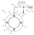
上述のように、ハウジング部材18や中空チューブ32,シール筒体36を含んで、管体12,14の接続部位において構成されたシール構造体16には、その使用に際して、更に、外部に給排手段としての圧力流体給排装置37が接続されることとなる。
As described above, the
かかる圧力流体給排装置37は、コンプレッサーやアキュムレータ,調圧機構を組み合わせて構成された、公知の空気圧源38を備えている。この空気圧源38は、予め設定された略一定の圧力空気を、その出力ポートから供給し得るようになっている。そして、この空気圧源38の出力ポートに対して、シール構造体16の給排口金具34が、空気圧管路40によって接続されている。
The pressure fluid supply /
また、空気圧管路40上には、電磁切換式の三方切換弁42が配設されており、この三方切換弁42の切換操作や開閉調節操作に従って、中空チューブ32の内部空間(作用流体室)に対して、空気圧源と大気中が選択的に接続されるようになっている。
Further, an electromagnetic switching type three-
更にまた、空気圧管路40上には、三方切換弁42よりも中空チューブ32側に位置して、圧力検出手段としての圧力センサ44が装着されている。この圧力センサ44によって、中空チューブ32の内部空間における空気圧が直接に検出されるようになっている。
Furthermore, a
このような構造とされたシール構造体16においては、例えば、三方切換弁42によって、空気圧源38の出力ポートを中空チューブ32の内部空所に接続して、中空チューブ32の内部空所に所定圧力の空気を充填し、中空チューブ32内が目的とする圧力になったことを圧力センサ44で確認した後、三方切換弁42を遮断して、中空チューブ32の内部空所を密閉状態に保持せしめることが出来る。
In the
これにより、中空チューブ32の内部空所が、所定の正圧に維持されることとなり、この圧力に基づいて、シール筒体36が、管体12,14に対して外周面から押し付けられて、それら両管体12,14の接続部分の端面間の隙間が流体密にシール保持せしめられることとなる。
Thereby, the internal space of the
或いは、例えば、三方切換弁42によって、空気圧源38の出力ポートを中空チューブ32の内部空所に接続した状態を維持せしめつつ、中空チューブ32内の圧力を圧力センサ44で継続的に検出する。そして、この圧力センサ44の検出信号を、コントローラに入力し、コントローラにおいて予め設定した目標圧力値と比較して、圧力センサ44の検出信号が目標圧力値に対して所定の誤差範囲に収まるように、三方切換弁42を切換作動せしめる。これにより、中空チューブ32の内部空所を空気圧源38と大気中とに適宜に切換作動せしめて、中空チューブ32の内部空所の圧力を、継続して、目標圧力値に維持するようにフィードバック制御することも出来る。
Alternatively, for example, the
これにより、中空チューブ32の内部空所が、所定の正圧となるように、一層高度に且つ高い信頼性をもって維持されることとなり、シール筒体36による両管体12,14の接続部分がシール保持されることとなる。
As a result, the internal space of the
或いはその他、適当な間隔で、圧力センサ44の検出値を取り込んで、それを記録しておくようにしても良い。このような記録をとっておくことにより、シール構造体16の経時的な変化や状態を効率的に把握することが可能となる。
Alternatively, the detection value of the
なお、中空チューブ32の膨出/収縮変形に伴って、ハウジング部材18とシール筒体36の間に形成された空間の空気は、例えば、ハウジング部材18の両端部と管体12,14の隙間を通じて、外部空間に対して給排されるようになっている。
It should be noted that the air in the space formed between the
このような本実施形態に従う構造とされた管体接続構造10においては、シール筒体36を管体12,14に対して等しい力で密着させられるため、管体の連結部におけるシール筒体36のシール性能を安定して発揮させることができる。更に、管体12,14の外周面からシール筒体36によって接合部を覆ってシールしているため、高度なシール性能を簡略な構造で実現できる。
In the
また、シール筒体36の全体に対して、周方向の全周に亘って略均一の押圧力が作用し、偏荷重が加わらない。それ故、シール筒体36による管体12,14間のシールが全体に亘って安定して実現され得ることとなり、周上の局部的な短絡(漏れ)や局所的な応力集中による損傷(リーク)が効果的に避けられて、シール筒体36の耐久性能の向上が実現され得る。
In addition, a substantially uniform pressing force acts on the
更に、シール構造体16は、管体12,14に対して外挿して、連結ボルト30によってボルト・ナット構造で継手側取付片22と管体側取付片26とを締結することにより取り付けられており、容易に着脱して管体の接続/分解ができる。それ故、頻繁に管体の分解及び再接続を行う必要がある場合にも好適に採用されて、接続/分解の作業性を向上することができる。
Further, the
更にまた、作用流体室としての中空チューブ32内の圧力を検出し、圧力の変動を検出した場合には、圧力流体給排装置37によって中空チューブ32内の圧力を自動的に略一定に保つようにしたことで、作用流体室としての中空チューブ32内の圧力が下がることによるシール性能の低下を、速やかに検出することが出来、労力や時間をかけることなくリークの防止が図られ得る。
Furthermore, when the pressure in the
また、本実施形態に従う管体接続構造10によれば、管体12,14がシール構造体16を介して固定的に連結される。それ故、管体をボルト等によって別途固定する必要がなく、配管作業の手間を省くことができる。
Moreover, according to the
次に、本発明の別の実施形態を、説明する。なお、以下に説明する各実施形態において、第一の実施形態に係る管体の接続構造と実質的に同様な構造とされた部材および部位に対しては、それぞれ、図中に、第一の実施形態と同一の符号を付すことにより詳細な説明を省略する。 Next, another embodiment of the present invention will be described. In each of the embodiments described below, for the members and parts that are substantially the same as the connection structure of the tubular body according to the first embodiment, Detailed description is omitted by giving the same reference numerals as those in the embodiment.
更に、図5に、本発明の第二の実施形態としての管体接続構造58が示されている。本実施形態の管体接続構造58を構成するシール構造体60は、前記第一の実施形態におけるシール構造体(16)と略同じ形状とされており、内周面に開口する環状凹所20を有している。ただし、この環状凹所20には中空チューブ(32)が配設されていない。
Further, FIG. 5 shows a
すなわち、シール構造体60の環状凹所20の開口部分には、円筒形状の可動蓋部材としての可動蓋62が配設されている。この可動蓋62は、第一の実施形態におけるシール筒体(36)と同様に、弾性変形可能で且つ管体12,14内を流動せしめられる流体に対する不透過性や耐久性などを考慮した材料によって形成されており、環状凹所20の開口部分に配設されている。しかし、シール筒体(36)とは異なり、環状凹所20の開口部を流体密に覆蓋し得るようになっている。これにより、環状凹所20内に作用流体室63が直接に形成されている。
That is, a
例えば、可動蓋62の軸方向両端部分は、シール構造体60に対して直接に接着されていたり、或いは可動蓋62の軸方向両端部に固着した金属リング等をシール構造体60に対して圧入や溶着等で固着することによって、シール構造体60の環状凹所20を流体密に覆蓋する構造で組み付けられていても良い。
For example, both ends of the
ここにおいて、本実施形態では、円筒形状を有する可動蓋62の軸方向両端縁部において、径方向外側へ向かって突出する環状シール片64,64が全周に亘って一体形成されている。これらの各環状シール片64は、図6にも示されているように、突出方向である外周側に向かって次第に薄肉となる断面形状とされている。特に、軸方向外側面は略軸直角方向に広がっているが、軸方向の内側面、即ち軸方向で一対の環状シール片64,64が互いに対向位置する面は、径方向外方に行くに従って互いに離隔する方向(軸方向外方)に向かう傾斜面とされている。
Here, in this embodiment,
そして、好適には、これら一対の環状シール片64,64は、外力が及ぼされていない自由状態下で、軸方向外側の面が、何れも、環状凹所20の内面に対して付勢力をもって押し付けられた状態で、かかる内面に沿って広がっている。
Preferably, the pair of
ここにおいて、作用流体室63に対して圧力流体給排装置37から空気が送り込まれると、作用流体室63内の圧力が上昇して、環状シール片64が圧力によって軸方向外方に広がる方向に変形,変位せしめられる。これにより、環状シール片64,64は、弾性変形して、ハウジング部材18における環状凹所20の開口部の両側壁の内面に対して押し付けられて密着状態とされる。これにより、作用流体室63の流体密性を確保することができるようになっている。
Here, when air is sent from the pressurized fluid supply /
このような構造とされた本実施形態に従う管体接続構造58においては、中空チューブ32を用いることなく簡単な構造によって流体密な作用流体室63を形成することができて、高度なシール性能を確保しつつ、部材点数の削減や製造の容易さを一層有利に実現できる。
In the
以上、本発明の実施形態の幾つかについて説明してきたが、これらはあくまでも例示であって、本発明は、かかる実施形態における具体的な記載によって、何等、限定的に解釈されるものではない。 Although some of the embodiments of the present invention have been described above, these are merely examples, and the present invention should not be construed as being limited to specific descriptions in the embodiments.
例えば、前記第一の実施形態では、作用流体室として中空チューブ32を採用したが、作用流体室として必ずしも中空チューブ32を用いる必要は無く、前記第二の実施形態に示すように、ハウジング部材18とシール筒体36の対向面間の空間を流体密に構成すると共に、圧力流体をかかる空間に充填することにより、作用流体室を形成することも可能である。
For example, in the first embodiment, the
また、前記第一又は第二の実施形態では、圧力流体として空気を採用した例を示したが、圧力流体としては、各種の気体の他、各種液体も採用され得る。なお、圧力流体として液体を選択する場合においては、環境に応じて不凍液等が適宜に採用されて好適に用いられる。
Moreover, although the example which employ | adopted air as a pressure fluid was shown in said 1st or 2nd embodiment, various liquids other than various gases can also be employ | adopted as a pressure fluid. In addition, when selecting a liquid as a pressure fluid, an antifreeze etc. are suitably employ | adopted and used suitably according to an environment.
更に、前記第一の実施形態においては、中空チューブ32を作用空気室として利用すると共に、シール筒体36を中空チューブ32とは別体として設けていたが、図7に示す如き本発明に従う構造とされた管体接続構造66のように、シール構造体68における中空チューブ32の内部空間を作用流体室として利用すると同時に、中空チューブ32の内周面をシール部材として使うことも可能である。
Further, in the first embodiment, while utilizing a
更に、作用流体室として中空チューブ32の内部空間を利用する場合においては、圧力流体の給排による中空チューブ32の変形を阻害する空気ばねの作用が、ハウジング部材18とシール筒体36間の空間において生じることを回避することが望ましく、前記第一又は第二の実施形態においては、ハウジング部材18とシール筒体36及び管体12,14との隙間から空気を排出することにより、空気ばねの作用を回避するものとした。しかしながら、空気ばねの作用を回避するための手段は前記実施形態の物に限定されず、具体的には、例えば、ハウジング部材18に、かかる空気ばねの作用を回避するための空気抜きのための孔を貫設して、より積極的に空気ばねの作用を回避することもできる。
Further, when the internal space of the
また、前記第一又は第二の実施形態において、作用流体室としての中空チューブ32内の圧力変動を検出する圧力センサ44が設けられていたが、このような圧力センサ44はなくてもよい。また、圧力センサ44は、必ずしも圧力流体給排装置37と連動している必要はなく、例えば、検出した圧力をモニターに常時表示したり、異常な圧力変動を検出した際に警報等の報知手段を作動させるようにしても良い。
In the first or second embodiment, the
更に、前記実施形態においては、三方切換弁42が設けられていたが、このような弁機構は、前記実施形態によって何ら限定されないし、弁機構以外の手段によって作用流体室内の圧力を制御することができれば、必ずしも設ける必要は無い。
Further, in the above embodiment, the three-
また、三方切換弁42に替えて、給排口金具34に対して、一方向弁を内蔵せしめると共に、中空チューブ32内の圧力を外部へ逃がすための圧力解放機構を備えることにより、弁機構を実現することもできる。なお、一方向弁と圧力解放機構を備えた給排口金具は、例えば、車両のタイヤなどに用いられる空気給排用のステムによって有利に実現することができる。これにより、簡単な構造で中空チューブ32内の圧力が逃げるのを防ぐことができると共に、着脱自在な給排手段、具体的には、例えば、タイヤの空気圧調整等に用いられるポンプ等を給排口金具34に取り付けて、外部から中空チューブ32内に圧力流体を供給できる一方、圧力開放機構によって中空チューブ32内に充填された圧力流体を外部へ開放することも可能である。
Further, in place of the three-
更にまた、前記第一又は第二の実施形態において、管体12,14及び管体12,14に固着される管体側取付片26は、何れも金属製としており、可鍛鋳鉄,炭素鋼,合金鋼,ステンレス鋼,アルミニウム等が好適に用いられるが、材質は金属でなくてもよく、硬質塩化ビニル製の管体等にも本発明は採用できる。なお、管体側取付片26の固設手段は、管体12,14及び管体側取付片26の材質などに応じて、接着や一体成型等、適宜に選択されるべきである。
Furthermore, in the first or second embodiment, the
更に、シール構造体を構成する各部材の材質に関しても、要求される機能を有するものであれば自由に採用できる。例えば、ハウジング部材18は必ずしも金属である必要はなく、塩化ビニル製等、作用流体室内に生じる圧力や、管体の重量負荷等によって破損しない強度を持つ材料であればよい。
Furthermore, the material of each member constituting the seal structure can be freely adopted as long as it has a required function. For example, the
10 管体接続構造
12 管体
14 管体
16 シール構造体
18 ハウジング部材
20 環状凹所
22 継手側取付片
24 継手側ボルト穴
26 管体側取付片
28 管体側ボルト穴
30 連結ボルト
32 中空チューブ
36 シール筒体
37 圧力流体給排装置
DESCRIPTION OF
Claims (7)
前記二本の管体の前記各一方の開口端部を互いに固定的に連結する連結手段を設ける一方、それら各一方の開口端部の突き合わせ部分の外周面に重ね合わせられるようにして外挿状態で配設される環状のシール部材を設けると共に、該シール部材の外周側を全周に亘って覆う環状のハウジング部材を設けて、該ハウジング部材と該シール部材の間に周方向で実質的に連続した作用流体室を形成し、該作用流体室に対して外部から圧力流体を給排することの出来る給排手段を設けて、該作用流体室に圧力流体を充填せしめて該シール部材に対して外周面から圧力を及ぼすことにより、該シール部材を該二本の管体の該各一方の開口端部の突き合わせ部分に対して外周面から密着させてシールするようにして、更に、該ハウジング部材の軸方向両端部分には、該二本の管体の各開口端部に設けた管体側取付片に対して連結ボルトで着脱可能に固定される継手側取付片を、周上の複数箇所に設けることにより、互いに接続されるそれら二本の管体を該ハウジング部材を利用して相互に連結したことを特徴とする管体の接続構造。 In the connection structure of the tubular body in which each open end of the two tubular bodies is connected in fluid-tight manner to each other in a butted state,
A connecting means for fixedly connecting the one open ends of the two pipes to each other is provided, while being extrapolated so as to be superposed on the outer peripheral surface of the butted portion of the one open end And an annular housing member that covers the outer periphery of the seal member over the entire circumference, and substantially between the housing member and the seal member in the circumferential direction. A continuous working fluid chamber is formed, and a supply / discharge means capable of supplying and discharging the pressure fluid from the outside to the working fluid chamber is provided, and the working fluid chamber is filled with the pressure fluid and the sealing member is By applying pressure from the outer peripheral surface, the sealing member is tightly sealed from the outer peripheral surface to the butted portion of the one open end of the two pipe bodies, and further the housing Both axial directions of the member In part, by the coupling-side mounting piece which is detachably fixed in connection bolt to the tube side attaching piece provided on the open end of the two tubular body, provided at a plurality of locations on the circumference, connection structure of the tubular body, characterized in that interconnected their two of the tube that are connected to each other by using the housing member.
The pipe connection according to any one of claims 1 to 6, wherein in each of the two pipe bodies, each of open end parts connected to each other is in a cut-off state with the shape of the main body part of the pipe body. Construction.
Priority Applications (1)
| Application Number | Priority Date | Filing Date | Title |
|---|---|---|---|
| JP2004160335A JP3921208B2 (en) | 2003-06-02 | 2004-05-28 | Tube connection structure |
Applications Claiming Priority (2)
| Application Number | Priority Date | Filing Date | Title |
|---|---|---|---|
| JP2003193219 | 2003-06-02 | ||
| JP2004160335A JP3921208B2 (en) | 2003-06-02 | 2004-05-28 | Tube connection structure |
Publications (2)
| Publication Number | Publication Date |
|---|---|
| JP2005016722A JP2005016722A (en) | 2005-01-20 |
| JP3921208B2 true JP3921208B2 (en) | 2007-05-30 |
Family
ID=34197099
Family Applications (1)
| Application Number | Title | Priority Date | Filing Date |
|---|---|---|---|
| JP2004160335A Expired - Fee Related JP3921208B2 (en) | 2003-06-02 | 2004-05-28 | Tube connection structure |
Country Status (1)
| Country | Link |
|---|---|
| JP (1) | JP3921208B2 (en) |
Cited By (1)
| Publication number | Priority date | Publication date | Assignee | Title |
|---|---|---|---|---|
| US11549622B2 (en) | 2018-05-21 | 2023-01-10 | Korea Railroad Research Institute | Sealing device for hyper tube |
Families Citing this family (10)
| Publication number | Priority date | Publication date | Assignee | Title |
|---|---|---|---|---|
| JP2007100790A (en) * | 2005-10-03 | 2007-04-19 | Bridgestone Corp | Sealing device |
| JP2009208824A (en) * | 2008-03-05 | 2009-09-17 | Toyo Hightech Kk | Powder and granular material discharging device |
| CH709441A2 (en) * | 2014-03-20 | 2015-09-30 | Theodor Wüst | Push-fit socket. |
| KR101950475B1 (en) | 2017-08-10 | 2019-02-20 | 한국철도기술연구원 | Tube infrastructure under negative pressure |
| CN108443511B (en) * | 2018-05-17 | 2024-11-26 | 苏州宝骅密封科技股份有限公司 | Axial sealing device with adjustable sealing pressure |
| CN108644493A (en) * | 2018-08-06 | 2018-10-12 | 天津长瑞大通流体控制系统有限公司 | The sealing structure and encapsulating method of highly pressurised liquid baffle type pipe connections |
| CN110005822B (en) * | 2018-12-29 | 2021-01-08 | 龙岩市海德馨汽车有限公司 | Control system and control method of inflatable sealing device |
| DE102019116326A1 (en) | 2019-06-14 | 2020-12-17 | Theodor WÜST | Pipe joint applicator and method of making a joint |
| CN110848505B (en) * | 2019-12-20 | 2025-03-14 | 北京吉瑞普管道技术有限公司 | A fire expansion device |
| KR102730143B1 (en) * | 2022-07-12 | 2024-11-13 | 현대건설(주) | Apparatus and method for sealing joint of concrete tube for hyper speed transformation system |
-
2004
- 2004-05-28 JP JP2004160335A patent/JP3921208B2/en not_active Expired - Fee Related
Cited By (1)
| Publication number | Priority date | Publication date | Assignee | Title |
|---|---|---|---|---|
| US11549622B2 (en) | 2018-05-21 | 2023-01-10 | Korea Railroad Research Institute | Sealing device for hyper tube |
Also Published As
| Publication number | Publication date |
|---|---|
| JP2005016722A (en) | 2005-01-20 |
Similar Documents
| Publication | Publication Date | Title |
|---|---|---|
| JP5416769B2 (en) | Extrusion prevention gasket face seal | |
| JP3921208B2 (en) | Tube connection structure | |
| EP2242947B1 (en) | Pipe coupling | |
| WO2013089120A1 (en) | Seal structure for flow-path connection part | |
| KR20100046104A (en) | Loose flange pipe joint | |
| JP3162992U (en) | Fitting gasket | |
| KR102745004B1 (en) | Coffin joint | |
| EP2542818A1 (en) | Pipe sealing tool with external and internal clamp | |
| KR20130105297A (en) | High-pressure tube fittings, seals, and end-face preparation tools | |
| CN109854818B (en) | A sealed pipeline elastic penetration vibration isolation device | |
| JP2013534996A (en) | Clamping ring for welded diaphragm | |
| JP7114111B2 (en) | Enclosure device and mounting method of enclosure device | |
| JP2008032113A (en) | Diaphragm-type valve | |
| JP6964879B2 (en) | Leakage repair structure and leak repair tool | |
| JP5719529B2 (en) | Union joint and seal structure of union joint | |
| JP2008002512A (en) | Fastening member for valve and butterfly valve using it | |
| WO2008062679A1 (en) | Fluid coupling | |
| JP4169832B2 (en) | Tubular repair method and mechanism | |
| JP4149036B2 (en) | Pipe flange leakage repair mechanism | |
| JP3229134U (en) | Metal tube connection structure | |
| JP2008128255A (en) | Fitting for piping | |
| JP2021076128A (en) | Leakage repair device | |
| US20120280495A1 (en) | Ceramic-to-metal flange connection | |
| CN222378524U (en) | Electronic expansion valve | |
| CN217302016U (en) | Pipeline joint |
Legal Events
| Date | Code | Title | Description |
|---|---|---|---|
| A621 | Written request for application examination |
Free format text: JAPANESE INTERMEDIATE CODE: A621 Effective date: 20051207 |
|
| A871 | Explanation of circumstances concerning accelerated examination |
Free format text: JAPANESE INTERMEDIATE CODE: A871 Effective date: 20051207 |
|
| A975 | Report on accelerated examination |
Free format text: JAPANESE INTERMEDIATE CODE: A971005 Effective date: 20051226 |
|
| A131 | Notification of reasons for refusal |
Free format text: JAPANESE INTERMEDIATE CODE: A131 Effective date: 20060117 |
|
| A521 | Written amendment |
Free format text: JAPANESE INTERMEDIATE CODE: A523 Effective date: 20060316 |
|
| A02 | Decision of refusal |
Free format text: JAPANESE INTERMEDIATE CODE: A02 Effective date: 20060606 |
|
| A521 | Written amendment |
Free format text: JAPANESE INTERMEDIATE CODE: A523 Effective date: 20060803 |
|
| A521 | Written amendment |
Free format text: JAPANESE INTERMEDIATE CODE: A523 Effective date: 20060912 |
|
| A911 | Transfer of reconsideration by examiner before appeal (zenchi) |
Free format text: JAPANESE INTERMEDIATE CODE: A911 Effective date: 20060919 |
|
| TRDD | Decision of grant or rejection written | ||
| A01 | Written decision to grant a patent or to grant a registration (utility model) |
Free format text: JAPANESE INTERMEDIATE CODE: A01 Effective date: 20070131 |
|
| A61 | First payment of annual fees (during grant procedure) |
Free format text: JAPANESE INTERMEDIATE CODE: A61 Effective date: 20070216 |
|
| R150 | Certificate of patent or registration of utility model |
Free format text: JAPANESE INTERMEDIATE CODE: R150 |
|
| FPAY | Renewal fee payment (event date is renewal date of database) |
Free format text: PAYMENT UNTIL: 20110223 Year of fee payment: 4 |
|
| FPAY | Renewal fee payment (event date is renewal date of database) |
Free format text: PAYMENT UNTIL: 20120223 Year of fee payment: 5 |
|
| FPAY | Renewal fee payment (event date is renewal date of database) |
Free format text: PAYMENT UNTIL: 20120223 Year of fee payment: 5 |
|
| FPAY | Renewal fee payment (event date is renewal date of database) |
Free format text: PAYMENT UNTIL: 20130223 Year of fee payment: 6 |
|
| FPAY | Renewal fee payment (event date is renewal date of database) |
Free format text: PAYMENT UNTIL: 20140223 Year of fee payment: 7 |
|
| R250 | Receipt of annual fees |
Free format text: JAPANESE INTERMEDIATE CODE: R250 |
|
| LAPS | Cancellation because of no payment of annual fees |