JP3912080B2 - Exhaust heat exchanger - Google Patents
Exhaust heat exchanger Download PDFInfo
- Publication number
- JP3912080B2 JP3912080B2 JP2001350437A JP2001350437A JP3912080B2 JP 3912080 B2 JP3912080 B2 JP 3912080B2 JP 2001350437 A JP2001350437 A JP 2001350437A JP 2001350437 A JP2001350437 A JP 2001350437A JP 3912080 B2 JP3912080 B2 JP 3912080B2
- Authority
- JP
- Japan
- Prior art keywords
- exhaust
- tube
- fin
- flow
- passage
- Prior art date
- Legal status (The legal status is an assumption and is not a legal conclusion. Google has not performed a legal analysis and makes no representation as to the accuracy of the status listed.)
- Expired - Fee Related
Links
Images


Classifications
-
- F—MECHANICAL ENGINEERING; LIGHTING; HEATING; WEAPONS; BLASTING
- F28—HEAT EXCHANGE IN GENERAL
- F28D—HEAT-EXCHANGE APPARATUS, NOT PROVIDED FOR IN ANOTHER SUBCLASS, IN WHICH THE HEAT-EXCHANGE MEDIA DO NOT COME INTO DIRECT CONTACT
- F28D7/00—Heat-exchange apparatus having stationary tubular conduit assemblies for both heat-exchange media, the media being in contact with different sides of a conduit wall
- F28D7/16—Heat-exchange apparatus having stationary tubular conduit assemblies for both heat-exchange media, the media being in contact with different sides of a conduit wall the conduits being arranged in parallel spaced relation
- F28D7/1684—Heat-exchange apparatus having stationary tubular conduit assemblies for both heat-exchange media, the media being in contact with different sides of a conduit wall the conduits being arranged in parallel spaced relation the conduits having a non-circular cross-section
-
- F—MECHANICAL ENGINEERING; LIGHTING; HEATING; WEAPONS; BLASTING
- F02—COMBUSTION ENGINES; HOT-GAS OR COMBUSTION-PRODUCT ENGINE PLANTS
- F02M—SUPPLYING COMBUSTION ENGINES IN GENERAL WITH COMBUSTIBLE MIXTURES OR CONSTITUENTS THEREOF
- F02M26/00—Engine-pertinent apparatus for adding exhaust gases to combustion-air, main fuel or fuel-air mixture, e.g. by exhaust gas recirculation [EGR] systems
- F02M26/13—Arrangement or layout of EGR passages, e.g. in relation to specific engine parts or for incorporation of accessories
- F02M26/22—Arrangement or layout of EGR passages, e.g. in relation to specific engine parts or for incorporation of accessories with coolers in the recirculation passage
- F02M26/29—Constructional details of the coolers, e.g. pipes, plates, ribs, insulation or materials
- F02M26/32—Liquid-cooled heat exchangers
-
- F—MECHANICAL ENGINEERING; LIGHTING; HEATING; WEAPONS; BLASTING
- F28—HEAT EXCHANGE IN GENERAL
- F28D—HEAT-EXCHANGE APPARATUS, NOT PROVIDED FOR IN ANOTHER SUBCLASS, IN WHICH THE HEAT-EXCHANGE MEDIA DO NOT COME INTO DIRECT CONTACT
- F28D7/00—Heat-exchange apparatus having stationary tubular conduit assemblies for both heat-exchange media, the media being in contact with different sides of a conduit wall
- F28D7/16—Heat-exchange apparatus having stationary tubular conduit assemblies for both heat-exchange media, the media being in contact with different sides of a conduit wall the conduits being arranged in parallel spaced relation
-
- F—MECHANICAL ENGINEERING; LIGHTING; HEATING; WEAPONS; BLASTING
- F28—HEAT EXCHANGE IN GENERAL
- F28F—DETAILS OF HEAT-EXCHANGE AND HEAT-TRANSFER APPARATUS, OF GENERAL APPLICATION
- F28F13/00—Arrangements for modifying heat-transfer, e.g. increasing, decreasing
- F28F13/06—Arrangements for modifying heat-transfer, e.g. increasing, decreasing by affecting the pattern of flow of the heat-exchange media
- F28F13/12—Arrangements for modifying heat-transfer, e.g. increasing, decreasing by affecting the pattern of flow of the heat-exchange media by creating turbulence, e.g. by stirring, by increasing the force of circulation
-
- F—MECHANICAL ENGINEERING; LIGHTING; HEATING; WEAPONS; BLASTING
- F28—HEAT EXCHANGE IN GENERAL
- F28F—DETAILS OF HEAT-EXCHANGE AND HEAT-TRANSFER APPARATUS, OF GENERAL APPLICATION
- F28F3/00—Plate-like or laminated elements; Assemblies of plate-like or laminated elements
- F28F3/02—Elements or assemblies thereof with means for increasing heat-transfer area, e.g. with fins, with recesses, with corrugations
- F28F3/025—Elements or assemblies thereof with means for increasing heat-transfer area, e.g. with fins, with recesses, with corrugations the means being corrugated, plate-like elements
- F28F3/027—Elements or assemblies thereof with means for increasing heat-transfer area, e.g. with fins, with recesses, with corrugations the means being corrugated, plate-like elements with openings, e.g. louvered corrugated fins; Assemblies of corrugated strips
-
- F—MECHANICAL ENGINEERING; LIGHTING; HEATING; WEAPONS; BLASTING
- F28—HEAT EXCHANGE IN GENERAL
- F28D—HEAT-EXCHANGE APPARATUS, NOT PROVIDED FOR IN ANOTHER SUBCLASS, IN WHICH THE HEAT-EXCHANGE MEDIA DO NOT COME INTO DIRECT CONTACT
- F28D21/00—Heat-exchange apparatus not covered by any of the groups F28D1/00 - F28D20/00
- F28D21/0001—Recuperative heat exchangers
- F28D21/0003—Recuperative heat exchangers the heat being recuperated from exhaust gases
Landscapes
- Engineering & Computer Science (AREA)
- Mechanical Engineering (AREA)
- General Engineering & Computer Science (AREA)
- Physics & Mathematics (AREA)
- Thermal Sciences (AREA)
- Chemical & Material Sciences (AREA)
- Combustion & Propulsion (AREA)
- Exhaust-Gas Circulating Devices (AREA)
- Heat-Exchange Devices With Radiators And Conduit Assemblies (AREA)
Description
【0001】
【発明の属する技術分野】
本発明は、内燃機関から排出される排気と冷却流体との間で熱交換を行う排気熱交換装置に関するもので、EGR(排気再循環装置)用の排気を冷却するEGRガス熱交換装置(EGRガスクーラ)に適用して有効である。
【0002】
【従来の技術及び発明が解決しようとする課題】
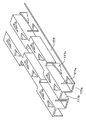
図11は出願人が試作検討しているEGRガスクーラ用のインナーフィンであり、このインナーフィンはEGRガスが流通するチューブ内に配設されてEGRガスと冷却水との熱交換を促進するものである。
【0003】
そして、この試作に係るインナーフィンでは、その一部を切り起こして三角状の突起部、すなわちウィング突起部111cを設けることにより、チューブ内の流通するEGRガスの流れを乱して渦を発生させて、インナーフィンとEGRガスとの熱伝達率の向上を図りながら、インナーフィン近傍のガス流速を高めてインナーフィンに付着したPaticurate Matters(すす)等の未燃焼物質を吹き飛ばしてPMがインナーフィンに堆積していくことを防止している。
【0004】
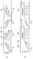
しかし、この試作に係るインナーフィンは、EGRガスの流通方向から見た断面形状が矩形波状となるように形成されているため、チューブ110内のガス通路は、図12に示すように、インナーフィン111により複数の通路に仕切られた状態となる。しかも、突起部111cはインナーフィン111により仕切られた通路の一面側のみに連続的に設けられているので、チューブ110内に流入したEGRガスの多くは、インナーフィン111により仕切られた通路のうち流通抵抗が小さい突起部が設けられていない側(図13の上方側)を流通する。
【0005】
このため、突起部111cに衝突するEGRガスが少なくなるので、チューブ内の流通するEGRガスの流れを十分に乱して渦を発生させることができず、十分な効果、つまり熱伝達率の向上及びPMの堆積防止を得ることができなかった。
【0006】
本発明は、上記点に鑑み、排気熱交換装置において、熱伝達率の向上及びPMの堆積防止を図ることを目的とする。
【0007】
【課題を解決するための手段】
本発明は、上記目的を達成するために、請求項1に記載の発明では、内燃機関から排出される排気と冷却流体との間で熱交換を行う排気熱交換装置であって、排気が流通する排気通路(110a)を構成するチューブ(110)と、チューブ内に配設され、チューブの内壁に接触する第1の平板部(111a)と、チューブ内を複数の通路に仕切る第2の平板部(111b)とを有し、排気の流通方向から見た断面形状が波状となるように形成されたフィン(111)とを備え、フィン(111)には、第1の平板部の一部が通路内方に向けて切り起こされることにより、排気流れに対して傾いた面(S)を有し、面の形状が排気流れ下流側に向かうほど第1の平板部からの突出寸法が大きくなる形状である突起部(111c)が設けられており、突起部は、排気の流通方向で異なる位置に、突出方向が互いに逆向きの関係である第1、第2の突起部が存在するように、排気の流通方向に沿って配置されていることを特徴とする。
【0008】
これにより、排気通路(110a)内のうち突起部(111c)が設けられていない流通抵抗が小さい部位のみに排気が流通するといった現象は発生し難く、排気は突起部(111c)に衝突して蛇行しながら流れるので、排気通路(1110a)全体として観察したとき、排気を突起部(111c)に略均等に衝突させることができる。
【0009】
したがって、確実に排気の流れを乱して渦を発生させることができるので、フィン(111)と排気との熱伝達率の向上を図りながら、フィン(111)及び排気通路(110a)の壁面近傍のガス流速を高めてフィン(111)及び排気通路(110a)の壁面に付着したPM等の未燃焼物質を吹き飛ばしてPMがフィン(111)及び排気通路(110a)の壁面に堆積していくことを防止することができる。
【0012】
請求項1に記載の発明では、突起部(111c)は、排気流れ下流側に向かうほどフィン(111)からの突出寸法が大きくなるように排気流れに対して傾いた面(S)を有している。
【0013】
これにより、排気通路(110a)内を流通する排気は、突起部(111c)に衝突した後、この衝突した突起部(111c)を乗り越えるようにして下流側に流れる。
【0014】
このとき、突起部(111c)のうち排気が衝突する側の面(以下、この面を衝突面と呼ぶ。)における排気圧が、これと反対側の面(以下、この面を背面と呼ぶ。)における排気圧に比べて高くなる。このため、衝突面に衝突した排気の一部が、突起部(111c)を超えて排気圧が低い背面に流れ込むため、突起部(111c)に衝突しないで流通する排気流れを背面に引き込むような連続した縦渦、つまり排気流れから見て、排気流れに対して直交する面内で渦を巻くように見える渦が発生する。
【0015】
したがって、平板部(111a)近傍を流通する排気が、突起部(111c)間に引き込むような連続した縦渦により後押しされるように加速されるので、フィン(111)の壁面近傍を流通する排気が、突起部(111c)を有していない単純な波状のストレートフィンに比べて大きくなる。
【0016】
延いては、排気とフィン(111)との熱伝達率を向上させることができるとともに、フィン(111)の表面に付着したPMを吹き飛ばすことができるので、フィン(111)の目詰まりを防止しつつ、排気熱交換装置の熱交換効率を向上させることができる。
【0017】
請求項3に記載の発明では、内燃機関から排出される排気と冷却流体との間で熱交換を行う排気熱交換装置であって、排気が流通する排気通路(110a)を構成するチューブ(110)と、チューブ内に配設され、チューブの内壁に接触する第1の平板部(111a)と、チューブ内を複数の通路に仕切る第2の平板部(111b)とを有し、排気の流通方向から見た断面形状が波状となるように形成されたフィンとを備え、フィンには、第1の平板部の一部が通路内方に向けて切り起こされることにより、排気流れに対して傾いた面(S)を有し、面の形状が排気流れ下流側に向かうほど第1の平板部からの突出寸法が大きくなる形状であり、かつ、排気流れに沿って千鳥状に並んだフィン側突起部(111c)が設けられ、チューブのフィン側突起部に対向する内壁面には、通路内方に向けて突出するチューブ側突起部(110c)が設けられており、フィン側突起部およびチューブ側突起部は、排気の流通方向に沿って、互いにずらして配置されていることを特徴とする。
【0018】
これにより、請求項1に記載の発明と同様に、排気は突起部(111c)に衝突して排気通路(110a)の長手方向と交差する方向に蛇行しながら排気通路(110a)内を流れるので、確実に排気の流れを乱して渦を発生させることができるので、フィン(111)と排気との熱伝達率の向上を図りながら、フィン(111)近傍のガス流速を高めてフィン(111)に付着したPM等の未燃焼物質を吹き飛ばしてPMがフィン(111)に堆積していくことを防止することができる。
【0020】
請求項5に記載の発明では、排気通路(110a)の長手方向と直交する方向から見て、フィン側突起部(111c)とチューブ側突起部(110c)とが交互に位置していることを特徴とする。
【0021】
これにより、確実にフィン(111)近傍のガス流速を高めてフィン(111)に付着したPM等の未燃焼物質を吹き飛ばしてPMがフィン(111)に堆積していくことを防止することができる。
【0022】
なお、請求項6に記載の発明のごとく、チューブ側突起部(110c)を排気通路(110a)を構成する部材に一体形成してもよい。
【0023】
また、請求項7に記載の発明のごとく、チューブ側突起部(110c)をプレス成形により排気通路(110a)を構成する部材から打ち出して形成してもよい。
【0024】
因みに、上記各手段の括弧内の符号は、後述する実施形態に記載の具体的手段との対応関係を示す一例である。
【0025】
【発明の実施の形態】
(第1実施形態)
本実施形態は、本発明に係る排気熱交換装置をディーゼル式のエンジン用EGRガス冷却装置に適用したものであり、図1は本実施形態に係るEGRガス冷却装置(以下、ガスクーラと呼ぶ。)100を用いたEGR(排気再循環装置)の模式図である。
【0026】
そして、排気再循環管210はエンジン200から排出される排気の一部をエンジン200の吸気側に還流させる配管である。
【0027】
EGRバルブ220は排気再循環管210の排気流れ途中に配設されて、エンジン200の稼働状態に応じてEGRガス量を調節する周知のものであり、ガスクーラ100は、エンジン200の排気側とEGRバルブ220との間に配設されてEGRガスとエンジンの冷却水との間で熱交換を行いEGRガスを冷却する。
【0028】
次に、ガスクーラ100の構造について述べる。
【0029】
図2はガスクーラの外観図(一部断面図)であり、チューブ110はEGRガスが流通する排気通路110aを構成する扁平状の管であり、このチューブ110は、図3に示すように、所定形状にプレス成形された2枚のプレート110bをろう付け接合することにより形成されている。
【0030】
また、チューブ110内、つまり排気通路110a内には、EGRガスと冷却水との熱交換を促進するインナーフィン111が配設されており、このインナーフィン111は、図4に示すように、EGRガスの流通方向に帯状に延びて互いに交差する2種類の平板部111a、111bを有し、EGRガスの流通方向から見た断面形状が矩形波状となるように形成されている。
【0031】
そして、インナーフィン111のうちチューブ110、つまりプレート110bの内壁に接触する部位である平板部111aには、その一部を切り起こすことにより、EGRガス流れ下流側に向かうほどインナーフィン111の平板部111aからの突出寸法が大きくなるようにEGRガス流れに対して傾いた三角状の面Sを有する突起部、すなわちウィング111cが設けられている。
【0032】
このとき、ウィング111cは、EGRガスの流通方向に対して直交する第1の向き(図4の紙面下側から上側に向かう向き)に突出した第1のウィング111cと、EGRガスの流通方向に対して直交する方向であって前記第1の向きと異なる向き(図4の紙面上側から下側に向かう向き)に突出した第2のウィング111cとが存在するように、インナーフィン111によって仕切られた各排気通路110aに沿って、三角状の面Sが千鳥状に変化するように設けられている。
【0033】
具体的には、EGRガス流れに対する面Sの傾斜方向が異なる2枚のウィング111cをEGRガス流れに沿って並べるとともに、この2枚のウィング111cのみを有する複数枚のインナーフィン111を、EGRガス流れに沿って交互に配置方向(上下方向)を反転させながらチューブ110内に配設することにより、上記したウィング111cの配置構造を実現している。
【0034】
因みに、インナーフィン111及びチューブ110は耐食性に優れた金属(本実施形態では、ステンレス)にプレス加工を施すことにより成形されており、インナーフィン111及びチューブ110はろう付けにより一体接合されている。
【0035】
また、図2中、ケーシング120は、複数本のチューブ110をその短径方向(紙面上下方向)に積層して接合した熱交換コア113を収納するとともに、熱交換コア113周りに冷却水が流通する冷却水通路121を形成する角パイプ状に形成されたものであり、このケーシング120は、耐食性に優れた金属(本実施形態では、ステンレス)製である。
【0036】
そして、ケーシング120の長手方向一端側(紙面右側)の開口部には、各チューブ110にEGRガスを分配供給するタンク部122aを形成するとともに、EGRガス配管(図示せず。)を接続するためのジョイント部122がろう付けされ、一方、長手方向他端側(紙面左側)の開口部には、熱交換を終えたEGRガスを各チューブ110から集合回収するタンク部123a形成するとともに、EGRガス配管(図示せず。)を接続するためのジョイント部123がろう付けされている。
【0037】
なお、コアプレート124はチューブ110を保持するとともに、冷却水通路121とタンク部122a、123aとを仕切るものであり、このコアプレート124及びジョイント部122、123も耐食性に優れた金属(本実施形態では、ステンレス)製である。
【0038】
また、ケーシング120のうちEGRガスの流入側には、チューブ110の長径方向側から冷却水を冷却水通路121内に導入する流入口125が設けられ、ケーシング120のうちEGRガスの流出側には、チューブ110の短径方向側から熱交換を終えた冷却水を排出する流出口126が設けられている。
【0039】
なお、本実施形態では、ケーシング120内におけるEGRガスも流通の向きと冷却水の流通の向きとを同一の向きとし、かつ、図2に示すように、チューブ110の外壁側にチューブ110の長径方向に延びる突起部110dを設けて、冷却水通路121のうち流入口125近傍を比較的に小さな空間に仕切り、EGRガス入口近傍における冷却水の流速を増大させる増速手段を構成しているとともに、チューブ110間の隙間寸法を確保する位置決め手段を構成している。
【0040】
因みに、図5中、突起部110eはチューブ110間の隙間寸法を確保しチューブ110とインナーフィン111とを確実にろう付けさせるためのものであり、図2中、補強リブ120eはケーシング120の補強用のものである。
【0041】
次に、本実施形態の特徴を述べる。
【0042】
図6は本実施形態に係るガスクーラ100のうちインナーフィン111にて仕切られた排気通路110a内のEGRガス流れを示す模式図であり、図6から明らかなように、本実施形態では、EGRガスの流通方向に対して直交する第1の向きに突出した第1のウィング111cと、EGRガスの流通方向に対して直交する方向であって前記第1の向きと異なる向きに突出した第2のウィング111cとを有しているので、巨視的に見て、EGRガスはウィング111cに衝突して排気通路110aの長手方向Doと直交する方向D1に蛇行しながら排気通路110a内を流れる。
【0043】
したがって、排気通路110a内のうちウィング111cが設けられていない流通抵抗が小さい部位のみにEGRガスが流通するといった現象は発生し難く、前述のごとく、EGRガスはウィング111cに衝突して蛇行しながら流れるので、チューブ110全体として観察したとき、EGRガスをウィング111cに略均等に衝突させることができる。
【0044】
延いては、確実にEGRガスの流れを乱して渦を発生させることができるので、インナーフィン111とEGRガスとの熱伝達率の向上を図りながら、インナーフィン111及びチューブ110の壁面近傍のガス流速を高めてインナーフィン111及びチューブ110の壁面に付着したPM等の未燃焼物質を吹き飛ばしてPMがインナーフィン111及びチューブ110の壁面に堆積していくことを防止することができる。
【0045】
(第2実施形態)
第1実施形態では、2枚のウィング111cのみを有する複数枚のインナーフィン111を、EGRガス流れに沿って交互に配置方向(上下方向)を反転させながらチューブ110内に配設することにより、上記したウィング111cの配置構造を実現したが、本実施形態は、図7に示すように、平板部111b、つまりインナーフィン111のうちチューブ110の短径方向と略平行な部位が千鳥状に配置されたオフセット型のインナーフィンに対して、EGRガスの流通方向に対して直交する第1の向きに突出した第1のウィング111cと、EGRガスの流通方向に対して直交する方向であって前記第1の向きと異なる向きに突出した第2のウィング111cとが存在するようにしたものである。
【0046】
そして、本実施形態では、1枚のインナーフィン111にてインナーインナーフィンを構成することができるので、ガスクーラ100の製造工数を低減することができる。
【0047】
(第3実施形態)
本実施形態は、排気通路110aと冷却水通路121とを区画して排気通路110aを構成するプレート110bに、図8に示すように、プレート110bの一部をプレス成形にて排気通路110a内側に打ち出して突起部110cを設けたものである。
【0048】
そして、これら突起部110cは、図9(a)に示すように、排気通路110aのうちウィング111cと対向する壁面において、排気流れに対して傾いた状態で排気流れに沿って千鳥状に複数個並んでいるとともに、図9(b)に示すように、排気通路110aの長手方向と直交する方向から見て、ウィング111cと突起部110cとが交互に位置するようになっている。因みに、図10は本実施形態に係るチューブ110の外観二面図である。
【0049】
これにより、第1実施形態と同様に、EGRガスはウィング111c及び突起部110cに衝突して排気通路110aの長手方向と直交する方向に蛇行しながら排気通路110a内を流れる。
【0050】
したがって、排気通路110a内のうちウィング111cや突起部110cが設けられていない流通抵抗が小さい部位のみにEGRガスが流通するといった現象は発生し難く、EGRガスはウィング111cに衝突して蛇行しながら流れるので、チューブ110全体として観察したとき、EGRガスをウィング111cに略均等に衝突させることができる。
【0051】
延いては、確実にEGRガスの流れを乱して渦を発生させることができるので、インナーフィン111とEGRガスとの熱伝達率の向上を図りながら、インナーフィン111及びチューブ110の壁面近傍のガス流速を高めてインナーフィン111及びチューブ110の壁面に付着したPM等の未燃焼物質を吹き飛ばしてPMがインナーフィン111及びチューブ110の壁面に堆積していくことを防止することができる。
【0052】
なお、本実施形態では、ウィング111cとEGRガスの流線とのなす角θ1と突起部110cとEGRガスの流線とのなす角θ2を等しくしたが、本実施形態はこれに限定されるものではない。
【0053】
また、本実施形態では、突起部110cの打ち出し寸法をウィング111cの最大突出寸法より小さくしたが、本実施形態はこれに限定されるものではない。
【0054】
(その他の実施形態)
上述の実施形態では、ウィング111cを三角状としたが、本発明はこれに限定されるものではなく、矩形状や半球(ドーム)状等のその他形状であってもよい。
【0055】
また、上述の実施形態では、ガスクーラ100に本発明に係る排気熱交換装置を適用したが、マフラー内に配設されて排気の熱エネルギを回収する熱交換器等のその他の熱交換器にも適用してもよい。
【0056】
また、上述実施形態では、インナーフィン111の一部を切り起こすことにより、ウィング111cを形成したが、本発明はこれに限定されるものではなく、インナーフィン111と別体の板状部材にウィング111cを形成し、このウィング111cが形成された板状部材をろう付け等の接合手段によりインナーフィン111に接合してウィング111cを形成してもよい。
【図面の簡単な説明】
【図1】本発明の第1実施形態に係るガスクーラを用いたEGRガス冷却装置の模式図である。
【図2】本発明の第1実施形態に係るガスクーラの外観図である。
【図3】本発明の第1実施形態に係るガスクーラのチューブの断面図である。
【図4】本発明の第1実施形態に係るガスクーラのインナーインナーフィンの斜視図である。
【図5】本発明の第1実施形態に係るガスクーラのチューブの半断面図である。
【図6】本発明の第1実施形態に係るガスクーラの特徴を説明するための説明図である。
【図7】本発明の第2実施形態に係るガスクーラのインナーインナーフィンの斜視図である。
【図8】本発明の第3実施形態に係るガスクーラのチューブの断面図である。
【図9】(a)は本発明の第3実施形態に係るガスクーラの特徴を説明するための説明図であり、(b)は(a)の上面図である。
【図10】本発明の第3実施形態に係るチューブ110の外観二面図である。
【図11】試作検討に係るガスクーラのインナーインナーフィンの斜視図である。
【図12】試作検討に係るガスクーラのチューブの断面図である。
【図13】試作検討に係るガスクーラの特徴を説明するための説明図である。
【符号の説明】
111…インナーインナーフィン、111c…ウィング(突起部)。[0001]
BACKGROUND OF THE INVENTION
The present invention relates to an exhaust heat exchange device that exchanges heat between exhaust gas discharged from an internal combustion engine and a cooling fluid, and an EGR gas heat exchange device (EGR) that cools exhaust gas for an EGR (exhaust gas recirculation device). It is effective when applied to a gas cooler.
[0002]
[Prior art and problems to be solved by the invention]
FIG. 11 shows an inner fin for an EGR gas cooler that the applicant has been experimentally examining. This inner fin is arranged in a tube through which the EGR gas flows and promotes heat exchange between the EGR gas and cooling water. is there.
[0003]
In the inner fin according to this prototype, a part of the inner fin is cut and raised to provide a triangular protrusion, that is, a
[0004]
However, since the inner fin according to this prototype is formed so that the cross-sectional shape viewed from the flow direction of the EGR gas has a rectangular wave shape, the gas passage in the
[0005]
For this reason, since the EGR gas that collides with the
[0006]
In view of the above points, an object of the present invention is to improve heat transfer coefficient and prevent PM accumulation in an exhaust heat exchanger.
[0007]
[Means for Solving the Problems]
In order to achieve the above object, the present invention provides an exhaust heat exchange device for exchanging heat between exhaust gas discharged from an internal combustion engine and a cooling fluid. a tube constituting the exhaust passage (110a) to (110), disposed within the tube, a first flat portion contacting the inner wall of the tube and (111a), a second flat plate which partitions the inside tube into a plurality of passages And a fin (111) formed so that a cross-sectional shape viewed from the flow direction of the exhaust has a wave shape, and the fin (111) includes a part of the first flat plate portion. Has a surface (S) inclined with respect to the exhaust flow, and the projecting dimension from the first flat plate portion increases as the shape of the surface moves toward the downstream side of the exhaust flow. Protrusions (111c) that are shaped Ri, protrusions at different positions in the flow direction of the exhaust, first, as the second protrusion is present protruding direction are opposite of each other, are arranged along the flow direction of the exhaust It is characterized by that.
[0008]
As a result, it is difficult for the phenomenon that the exhaust gas circulates only in the portion of the exhaust passage (110a) where the projection portion (111c) is not provided and the flow resistance is small, and the exhaust collides with the projection portion (111c). Since it flows while meandering, the exhaust can collide with the protrusion (111c) substantially evenly when observed as the whole exhaust passage (1110a).
[0009]
Therefore, since the exhaust flow can be reliably disturbed to generate vortices, the heat transfer coefficient between the fin (111) and the exhaust is improved, and the vicinity of the wall surface of the fin (111) and the exhaust passage (110a). To increase the gas flow rate and blow off unburned substances such as PM adhering to the wall surfaces of the fin (111) and the exhaust passage (110a) to deposit PM on the wall surface of the fin (111) and the exhaust passage (110a). Can be prevented.
[0012]
In the first aspect of the present invention, the protrusion (111c) has a surface (S) that is inclined with respect to the exhaust flow so that the protrusion dimension from the fin (111) increases toward the exhaust flow downstream side. It is .
[0013]
As a result, the exhaust gas flowing through the exhaust passage (110a) collides with the projection (111c) and then flows downstream so as to get over the collided projection (111c).
[0014]
At this time, the exhaust pressure on the surface of the protrusion (111c) on which the exhaust collides (hereinafter, this surface is referred to as a collision surface) is the opposite surface (hereinafter, this surface is referred to as the back surface). ) Higher than the exhaust pressure in For this reason, a part of the exhaust gas colliding with the collision surface flows into the back surface where the exhaust pressure is low beyond the projection portion (111c), so that the exhaust flow flowing without colliding with the projection portion (111c) is drawn into the back surface. A continuous vertical vortex, that is, a vortex that appears to vortex in a plane perpendicular to the exhaust flow when viewed from the exhaust flow, is generated.
[0015]
Therefore, since the exhaust gas flowing in the vicinity of the flat plate portion (111a) is accelerated so as to be boosted by the continuous vertical vortex that is drawn between the protrusions (111c), the exhaust gas flowing in the vicinity of the wall surface of the fin (111). However, it becomes larger than a simple wavy straight fin that does not have the protrusion (111c).
[0016]
As a result, the heat transfer coefficient between the exhaust and the fin (111) can be improved, and the PM adhering to the surface of the fin (111) can be blown away, thereby preventing clogging of the fin (111). Meanwhile, the heat exchange efficiency of the exhaust heat exchange device can be improved.
[0017]
The invention according to claim 3 is an exhaust heat exchange device for exchanging heat between the exhaust discharged from the internal combustion engine and the cooling fluid, and a tube (110 ) constituting the exhaust passage (110a) through which the exhaust flows. ) and is disposed within the tube, a first plate portion which contacts the inner wall of the tube and (111a), a second plate portion which partitions the inside tube into a plurality of passages and (111b), the flow of the exhaust And a fin formed so that the cross-sectional shape viewed from the direction is wavy, and the fin has a part of the first flat plate portion cut and raised toward the inside of the passage to prevent the exhaust flow. has a plane inclined (S), a projecting dimension becomes large shape from the first plate portion as the shape of the surface is directed to the exhaust gas flow downstream side, and arranged in a zigzag form along the exhaust gas flow fin side protrusions (111c) is provided, the tube A tube-side protrusion (110c) that protrudes toward the inside of the passage is provided on the inner wall surface facing the fin-side protrusion, and the fin-side protrusion and the tube-side protrusion are arranged in the exhaust flow direction. And are arranged so as to be shifted from each other .
[0018]
As a result, the exhaust gas collides with the protrusion (111c) and flows in the exhaust passage (110a) while meandering in the direction intersecting with the longitudinal direction of the exhaust passage (110a). Since the exhaust flow can be reliably disturbed to generate vortices, the gas flow rate in the vicinity of the fin (111) is increased to improve the heat transfer coefficient between the fin (111) and the exhaust, thereby improving the fin (111). It is possible to prevent PM from accumulating on the fin (111) by blowing off unburned substances such as PM adhering to the fin (111).
[0020]
The invention according to claim 5, when viewed from the direction perpendicular to the longitudinal direction of the exhaust passage (110a), that the fin-side projections (111c) and the tube-side projection and (110c) are located alternately Features.
[0021]
Thereby, it is possible to reliably increase the gas flow rate in the vicinity of the fin (111) and blow off unburned substances such as PM adhering to the fin (111) to prevent PM from being deposited on the fin (111). .
[0022]
Incidentally, as in the invention described in claim 6, it may be integrally formed on the member constituting the exhaust passage (110 a) tube-side protruding portion (110c).
[0023]
Also, as in the invention described in claim 7, it may be formed launch of a member constituting the exhaust passage (110 a) tube-side protruding portion (110c) by press molding.
[0024]
Incidentally, the reference numerals in parentheses of each means described above are an example showing the correspondence with the specific means described in the embodiments described later.
[0025]
DETAILED DESCRIPTION OF THE INVENTION
(First embodiment)
In the present embodiment, the exhaust heat exchanger according to the present invention is applied to an EGR gas cooling device for a diesel engine, and FIG. 1 shows an EGR gas cooling device (hereinafter referred to as a gas cooler) according to the present embodiment. 1 is a schematic diagram of an EGR (exhaust gas recirculation device) using 100. FIG.
[0026]
The exhaust
[0027]
The
[0028]
Next, the structure of the
[0029]
FIG. 2 is an external view (partially sectional view) of the gas cooler, and the
[0030]
Further, in the
[0031]
And the
[0032]
At this time, the
[0033]
Specifically, two
[0034]
Incidentally, the
[0035]
In FIG. 2, the
[0036]
A
[0037]
The
[0038]
Further, an
[0039]
In the present embodiment, the direction of the EGR gas in the
[0040]
Incidentally, in FIG. 5, the
[0041]
Next, features of the present embodiment will be described.
[0042]
FIG. 6 is a schematic diagram showing an EGR gas flow in the
[0043]
Therefore, the phenomenon that the EGR gas flows only in a portion where the
[0044]
As a result, the flow of the EGR gas can be reliably disturbed to generate vortices, so that the heat transfer coefficient between the
[0045]
(Second Embodiment)
In the first embodiment, by disposing a plurality of
[0046]
And in this embodiment, since the inner inner fin can be comprised with the one
[0047]
(Third embodiment)
In this embodiment, the
[0048]
Then, as shown in FIG. 9A, a plurality of these projecting
[0049]
Thus, as in the first embodiment, the EGR gas collides with the
[0050]
Therefore, the phenomenon that EGR gas circulates only in the portion of the
[0051]
As a result, the flow of the EGR gas can be reliably disturbed to generate vortices, so that the heat transfer coefficient between the
[0052]
In the present embodiment, the angle θ1 formed by the
[0053]
In this embodiment, the projecting dimension of the
[0054]
(Other embodiments)
In the above-described embodiment, the
[0055]
In the above-described embodiment, the exhaust heat exchanger according to the present invention is applied to the
[0056]
Further, in the above-described embodiment, the
[Brief description of the drawings]
FIG. 1 is a schematic diagram of an EGR gas cooling apparatus using a gas cooler according to a first embodiment of the present invention.
FIG. 2 is an external view of a gas cooler according to the first embodiment of the present invention.
FIG. 3 is a sectional view of the tube of the gas cooler according to the first embodiment of the present invention.
FIG. 4 is a perspective view of an inner inner fin of the gas cooler according to the first embodiment of the present invention.
FIG. 5 is a half sectional view of the tube of the gas cooler according to the first embodiment of the present invention.
FIG. 6 is an explanatory diagram for explaining the characteristics of the gas cooler according to the first embodiment of the present invention.
FIG. 7 is a perspective view of an inner inner fin of a gas cooler according to a second embodiment of the present invention.
FIG. 8 is a sectional view of a tube of a gas cooler according to a third embodiment of the present invention.
FIG. 9A is an explanatory view for explaining the characteristics of a gas cooler according to a third embodiment of the present invention, and FIG. 9B is a top view of FIG. 9A.
FIG. 10 is a two-sided external view of a
FIG. 11 is a perspective view of an inner inner fin of a gas cooler according to a prototype study.
FIG. 12 is a cross-sectional view of a gas cooler tube according to a prototype study.
FIG. 13 is an explanatory diagram for explaining the characteristics of the gas cooler according to the trial examination.
[Explanation of symbols]
111 ... Inner inner fin, 111c ... Wing (projection).
Claims (7)
排気が流通する排気通路(110a)を構成するチューブ(110)と、
前記チューブ内に配設され、前記チューブの内壁に接触する第1の平板部(111a)と、前記チューブ内を複数の通路に仕切る第2の平板部(111b)とを有し、排気の流通方向から見た断面形状が波状となるように形成されたフィン(111)とを備え、
前記フィン(111)には、前記第1の平板部の一部が前記通路内方に向けて切り起こされることにより、排気流れに対して傾いた面(S)を有し、前記面の形状が排気流れ下流側に向かうほど前記第1の平板部からの突出寸法が大きくなる形状である突起部(111c)が設けられており、
前記突起部は、排気の流通方向で異なる位置に、突出方向が互いに逆向きの関係である第1、第2の突起部が存在するように、排気の流通方向に沿って配置されていることを特徴とする排気熱交換装置。An exhaust heat exchange device for exchanging heat between exhaust gas discharged from an internal combustion engine and a cooling fluid,
A tube (110) constituting an exhaust passage (110a) through which exhaust flows,
Disposed within said tube has a first flat portion contacting the inner wall of the tube and (111a), a second plate portion which partitions the inside of the tube into a plurality of passages and (111b), the flow of the exhaust A fin (111) formed so that a cross-sectional shape viewed from the direction is wavy,
The fin (111) has a surface (S) inclined with respect to the exhaust flow by part of the first flat plate portion being cut and raised toward the inside of the passage, and the shape of the surface Is provided with a protrusion (111c) having a shape in which the protrusion dimension from the first flat plate portion increases toward the exhaust flow downstream side,
The protrusions are arranged along the exhaust flow direction so that there are first and second protrusions whose protrusion directions are opposite to each other at different positions in the exhaust flow direction . Exhaust heat exchange device characterized by.
排気が流通する排気通路(110a)を構成するチューブ(110)と、
前記チューブ内に配設され、前記チューブの内壁に接触する第1の平板部(111a)と、前記チューブ内を複数の通路に仕切る第2の平板部(111b)とを有し、排気の流通方向から見た断面形状が波状となるように形成されたフィンとを備え、
前記フィン(111)には、前記第1の平板部の一部が前記通路内方に向けて切り起こされることにより、排気流れに対して傾いた面(S)を有し、前記面の形状が排気流れ下流側に向かうほど前記第1の平板部からの突出寸法が大きくなる形状であり、かつ、排気流れに沿って千鳥状に並んだフィン側突起部(111c)が設けられ、
前記チューブのフィン側突起部に対向する内壁面には、前記通路内方に向けて突出するチューブ側突起部(110c)が設けられており、
前記フィン側突起部およびチューブ側突起部は、排気の流通方向に沿って、互いにずらして配置されていることを特徴とする排気熱交換装置。An exhaust heat exchange device for exchanging heat between exhaust gas discharged from an internal combustion engine and a cooling fluid,
A tube (110) constituting an exhaust passage (110a) through which exhaust flows,
A first flat plate portion (111a) disposed in the tube and in contact with the inner wall of the tube, and a second flat plate portion (111b) for partitioning the inside of the tube into a plurality of passages, and circulation of exhaust gas With fins formed so that the cross-sectional shape seen from the direction is wavy,
The fin (111) has a surface (S) inclined with respect to the exhaust flow by part of the first flat plate portion being cut and raised toward the inside of the passage, and the shape of the surface Is provided with fin-side projections (111c) arranged in a staggered manner along the exhaust flow, with the projecting dimension from the first flat plate portion increasing toward the downstream side of the exhaust flow.
An inner wall surface facing the fin-side protrusion of the tube is provided with a tube-side protrusion (110c) protruding toward the inside of the passage,
The exhaust heat exchanger according to claim 1, wherein the fin-side protrusion and the tube-side protrusion are arranged so as to be shifted from each other along a flow direction of the exhaust.
Priority Applications (4)
| Application Number | Priority Date | Filing Date | Title |
|---|---|---|---|
| JP2001350437A JP3912080B2 (en) | 2001-07-25 | 2001-11-15 | Exhaust heat exchanger |
| EP09008132.4A EP2096294B1 (en) | 2001-07-25 | 2002-07-25 | Exhaust gas heat exchanger |
| PCT/JP2002/007566 WO2003010481A1 (en) | 2001-07-25 | 2002-07-25 | Exhaust gas heat exchanger |
| EP20020751694 EP1411315B1 (en) | 2001-07-25 | 2002-07-25 | Exhaust gas heat exchanger |
Applications Claiming Priority (3)
| Application Number | Priority Date | Filing Date | Title |
|---|---|---|---|
| JP2001224651 | 2001-07-25 | ||
| JP2001-224651 | 2001-07-25 | ||
| JP2001350437A JP3912080B2 (en) | 2001-07-25 | 2001-11-15 | Exhaust heat exchanger |
Publications (2)
| Publication Number | Publication Date |
|---|---|
| JP2003106785A JP2003106785A (en) | 2003-04-09 |
| JP3912080B2 true JP3912080B2 (en) | 2007-05-09 |
Family
ID=26619245
Family Applications (1)
| Application Number | Title | Priority Date | Filing Date |
|---|---|---|---|
| JP2001350437A Expired - Fee Related JP3912080B2 (en) | 2001-07-25 | 2001-11-15 | Exhaust heat exchanger |
Country Status (3)
| Country | Link |
|---|---|
| EP (2) | EP2096294B1 (en) |
| JP (1) | JP3912080B2 (en) |
| WO (1) | WO2003010481A1 (en) |
Families Citing this family (33)
| Publication number | Priority date | Publication date | Assignee | Title |
|---|---|---|---|---|
| DE10214467A1 (en) | 2002-03-30 | 2003-10-09 | Modine Mfg Co | Exhaust gas heat exchanger for motor vehicles |
| JP3879614B2 (en) * | 2002-07-25 | 2007-02-14 | 株式会社デンソー | Heat exchanger |
| JP4148080B2 (en) * | 2003-09-17 | 2008-09-10 | 株式会社デンソー | Heat exchanger |
| DE10359806A1 (en) * | 2003-12-19 | 2005-07-14 | Modine Manufacturing Co., Racine | Heat exchanger with flat tubes and flat heat exchanger tube |
| DE102004026797A1 (en) * | 2004-06-02 | 2005-12-22 | Daimlerchrysler Ag | Internal combustion engine with exhaust aftertreatment system and a method for controlling the exhaust gas temperature |
| US20070000652A1 (en) * | 2005-06-30 | 2007-01-04 | Ayres Steven M | Heat exchanger with dimpled tube surfaces |
| JP4756585B2 (en) * | 2005-09-09 | 2011-08-24 | 臼井国際産業株式会社 | Heat exchanger tube for heat exchanger |
| US8967235B2 (en) | 2005-10-26 | 2015-03-03 | Behr Gmbh & Co. Kg | Heat exchanger, method for the production of a heat exchanger |
| DE102005053924B4 (en) | 2005-11-11 | 2016-03-31 | Modine Manufacturing Co. | Intercooler in plate construction |
| DE102005055481A1 (en) | 2005-11-18 | 2007-05-24 | Behr Gmbh & Co. Kg | Heat exchanger for an internal combustion engine |
| US8424592B2 (en) | 2007-01-23 | 2013-04-23 | Modine Manufacturing Company | Heat exchanger having convoluted fin end and method of assembling the same |
| US20090250201A1 (en) | 2008-04-02 | 2009-10-08 | Grippe Frank M | Heat exchanger having a contoured insert and method of assembling the same |
| JP2008275183A (en) * | 2007-04-25 | 2008-11-13 | Ihi Corp | Heat exchanger, manufacturing method of heat exchanger and egr system |
| JP5107603B2 (en) * | 2007-04-26 | 2012-12-26 | 株式会社ティラド | Heat exchanger |
| JP4569621B2 (en) | 2007-11-30 | 2010-10-27 | トヨタ自動車株式会社 | Intake mixed gas introduction device |
| JP4683111B2 (en) * | 2008-10-17 | 2011-05-11 | 株式会社デンソー | Exhaust heat exchanger |
| JP5533715B2 (en) | 2010-04-09 | 2014-06-25 | 株式会社デンソー | Exhaust heat exchanger |
| CN102853707B (en) * | 2011-06-30 | 2015-12-02 | 杭州三花研究院有限公司 | A kind of heat exchanger plate and Double-flow-channel heat exchanger |
| JP5768795B2 (en) * | 2011-10-18 | 2015-08-26 | カルソニックカンセイ株式会社 | Exhaust heat exchanger |
| JP5887115B2 (en) * | 2011-11-30 | 2016-03-16 | 東京ラヂエーター製造株式会社 | Inner fin |
| JP5904108B2 (en) | 2011-12-19 | 2016-04-13 | 株式会社デンソー | Exhaust heat exchanger |
| JP5915187B2 (en) * | 2012-01-10 | 2016-05-11 | マツダ株式会社 | Heat exchanger |
| EP2638961A1 (en) * | 2012-03-14 | 2013-09-18 | Alfa Laval Corporate AB | Residence time plate |
| DE202013011854U1 (en) * | 2012-11-26 | 2014-08-12 | Ti Automotive Engineering Centre (Heidelberg) Gmbh | Internal heat exchanger for an air conditioner |
| JP6203080B2 (en) * | 2013-04-23 | 2017-09-27 | カルソニックカンセイ株式会社 | Heat exchanger |
| JP6094534B2 (en) * | 2014-06-10 | 2017-03-15 | トヨタ自動車株式会社 | EGR passage |
| JP6474023B2 (en) * | 2014-09-26 | 2019-02-27 | Toto株式会社 | Solid oxide fuel cell device |
| JP6382696B2 (en) * | 2014-11-20 | 2018-08-29 | カルソニックカンセイ株式会社 | Heat exchanger |
| JP6327271B2 (en) * | 2015-04-17 | 2018-05-23 | 株式会社デンソー | Heat exchanger |
| US11262142B2 (en) | 2016-04-26 | 2022-03-01 | Northrop Grumman Systems Corporation | Heat exchangers, weld configurations for heat exchangers and related systems and methods |
| ES2679868B1 (en) * | 2017-02-16 | 2019-06-21 | Valeo Termico Sa | HEAT EXCHANGER FOR GASES, ESPECIALLY FOR AN ENGINE EXHAUST GAS, AND MANUFACTURING METHOD OF SUCH EXCHANGER |
| US11454448B2 (en) | 2017-11-27 | 2022-09-27 | Dana Canada Corporation | Enhanced heat transfer surface |
| JP6550177B1 (en) * | 2018-07-20 | 2019-07-24 | カルソニックカンセイ株式会社 | Heat exchanger |
Family Cites Families (17)
| Publication number | Priority date | Publication date | Assignee | Title |
|---|---|---|---|---|
| US3363682A (en) * | 1964-07-09 | 1968-01-16 | Int Combustion Holdings Ltd | Heat exchangers having vortex producing vanes |
| JPS5827337Y2 (en) * | 1976-10-30 | 1983-06-14 | 東芝熱器具株式会社 | Heat exchanger |
| JPS60139182U (en) * | 1984-02-23 | 1985-09-14 | 三菱自動車工業株式会社 | heat exchange equipment |
| JPH0249512Y2 (en) * | 1985-02-15 | 1990-12-26 | ||
| JPS6239183U (en) * | 1985-08-29 | 1987-03-09 | ||
| DE3739619A1 (en) * | 1987-11-23 | 1988-04-07 | Martin Prof Dr Ing Fiebig | Funnel vortex generators and heat exchange (transfer) surfaces for heat exchangers |
| JPH01151082U (en) * | 1988-04-06 | 1989-10-18 | ||
| US4984626A (en) * | 1989-11-24 | 1991-01-15 | Carrier Corporation | Embossed vortex generator enhanced plate fin |
| US5107922A (en) * | 1991-03-01 | 1992-04-28 | Long Manufacturing Ltd. | Optimized offset strip fin for use in contact heat exchangers |
| DE9406197U1 (en) * | 1994-04-14 | 1994-06-16 | Behr Gmbh & Co | Heat exchanger for cooling exhaust gas from a motor vehicle engine |
| JP3403544B2 (en) * | 1995-03-31 | 2003-05-06 | 昭和電工株式会社 | Heat exchanger |
| DE19654363B4 (en) * | 1996-12-24 | 2007-09-27 | Behr Gmbh & Co. Kg | Exhaust gas heat exchanger for an internal combustion engine |
| DE19654367A1 (en) * | 1996-12-24 | 1998-06-25 | Behr Gmbh & Co | Method for attaching tabs and / or protrusions to a sheet and sheet with tabs and / or devices and rectangular tube made of sheet |
| JP3678262B2 (en) * | 1997-10-06 | 2005-08-03 | 株式会社ノーリツ | Fin pipe turbulence generator |
| DE19833338A1 (en) * | 1998-07-24 | 2000-01-27 | Modine Mfg Co | Heat exchangers, in particular exhaust gas heat exchangers |
| JP2000161888A (en) * | 1998-12-01 | 2000-06-16 | Sanden Corp | Heat exchanger |
| DE60000493T2 (en) * | 1999-07-30 | 2003-02-20 | Denso Corp., Kariya | Exhaust gas heat exchanger with gas guide segments arranged at an angle |
-
2001
- 2001-11-15 JP JP2001350437A patent/JP3912080B2/en not_active Expired - Fee Related
-
2002
- 2002-07-25 EP EP09008132.4A patent/EP2096294B1/en not_active Expired - Lifetime
- 2002-07-25 EP EP20020751694 patent/EP1411315B1/en not_active Expired - Lifetime
- 2002-07-25 WO PCT/JP2002/007566 patent/WO2003010481A1/en active Application Filing
Also Published As
| Publication number | Publication date |
|---|---|
| EP1411315B1 (en) | 2015-04-22 |
| JP2003106785A (en) | 2003-04-09 |
| EP2096294B1 (en) | 2015-07-08 |
| WO2003010481A1 (en) | 2003-02-06 |
| EP2096294A3 (en) | 2009-11-04 |
| EP2096294A2 (en) | 2009-09-02 |
| EP1411315A4 (en) | 2009-10-28 |
| EP1411315A1 (en) | 2004-04-21 |
Similar Documents
| Publication | Publication Date | Title |
|---|---|---|
| JP3912080B2 (en) | Exhaust heat exchanger | |
| US6820682B2 (en) | Heat exchanger | |
| US6318455B1 (en) | Heat exchanger | |
| US8069905B2 (en) | EGR gas cooling device | |
| JP4683111B2 (en) | Exhaust heat exchanger | |
| EP1520144B1 (en) | Stacked plate heat exchanger | |
| JP3729136B2 (en) | Exhaust heat exchanger | |
| JP4143966B2 (en) | Flat tube for EGR cooler | |
| EP1505360A1 (en) | Heat transfer pipe and heat exchange incorporating such heat transfer pipe | |
| KR20060101481A (en) | Heat exchanger having a flow path of the heat exchanger and the flow path | |
| EP3436761B1 (en) | Heat exchanger utilized as an egr cooler in a gas recirculation system | |
| JP2007500836A (en) | Heat exchanger and manufacturing method thereof | |
| JP4069570B2 (en) | Exhaust heat exchanger | |
| JP3744432B2 (en) | Exhaust heat exchanger | |
| JP2003279293A (en) | Exhaust heat exchanger | |
| JP3985509B2 (en) | Exhaust heat exchanger | |
| JP2001174169A (en) | Heat exchanger | |
| JP3879614B2 (en) | Heat exchanger | |
| CN112368535B (en) | Heat exchanger | |
| JP4622150B2 (en) | Heat exchanger | |
| JP2003185374A (en) | Tube for heat exchanger with optimized plate | |
| JP3446427B2 (en) | Heat exchanger | |
| JP2001041109A (en) | Exhaust heat exchanger | |
| JP4035651B2 (en) | Exhaust heat exchanger | |
| JP2003227695A (en) | Exhaust heat exchanger |
Legal Events
| Date | Code | Title | Description |
|---|---|---|---|
| A621 | Written request for application examination |
Free format text: JAPANESE INTERMEDIATE CODE: A621 Effective date: 20040107 |
|
| A131 | Notification of reasons for refusal |
Free format text: JAPANESE INTERMEDIATE CODE: A131 Effective date: 20061003 |
|
| A521 | Written amendment |
Free format text: JAPANESE INTERMEDIATE CODE: A523 Effective date: 20061204 |
|
| TRDD | Decision of grant or rejection written | ||
| A01 | Written decision to grant a patent or to grant a registration (utility model) |
Free format text: JAPANESE INTERMEDIATE CODE: A01 Effective date: 20070109 |
|
| A61 | First payment of annual fees (during grant procedure) |
Free format text: JAPANESE INTERMEDIATE CODE: A61 Effective date: 20070122 |
|
| R150 | Certificate of patent or registration of utility model |
Free format text: JAPANESE INTERMEDIATE CODE: R150 Ref document number: 3912080 Country of ref document: JP Free format text: JAPANESE INTERMEDIATE CODE: R150 |
|
| FPAY | Renewal fee payment (event date is renewal date of database) |
Free format text: PAYMENT UNTIL: 20110209 Year of fee payment: 4 |
|
| FPAY | Renewal fee payment (event date is renewal date of database) |
Free format text: PAYMENT UNTIL: 20120209 Year of fee payment: 5 |
|
| FPAY | Renewal fee payment (event date is renewal date of database) |
Free format text: PAYMENT UNTIL: 20130209 Year of fee payment: 6 |
|
| FPAY | Renewal fee payment (event date is renewal date of database) |
Free format text: PAYMENT UNTIL: 20140209 Year of fee payment: 7 |
|
| R250 | Receipt of annual fees |
Free format text: JAPANESE INTERMEDIATE CODE: R250 |
|
| R250 | Receipt of annual fees |
Free format text: JAPANESE INTERMEDIATE CODE: R250 |
|
| S802 | Written request for registration of partial abandonment of right |
Free format text: JAPANESE INTERMEDIATE CODE: R311802 |
|
| R350 | Written notification of registration of transfer |
Free format text: JAPANESE INTERMEDIATE CODE: R350 |
|
| R250 | Receipt of annual fees |
Free format text: JAPANESE INTERMEDIATE CODE: R250 |
|
| R250 | Receipt of annual fees |
Free format text: JAPANESE INTERMEDIATE CODE: R250 |
|
| R250 | Receipt of annual fees |
Free format text: JAPANESE INTERMEDIATE CODE: R250 |
|
| R250 | Receipt of annual fees |
Free format text: JAPANESE INTERMEDIATE CODE: R250 |
|
| LAPS | Cancellation because of no payment of annual fees |