JP3905149B2 - Computer system for quality control correlation - Google Patents
Computer system for quality control correlation Download PDFInfo
- Publication number
- JP3905149B2 JP3905149B2 JP14208496A JP14208496A JP3905149B2 JP 3905149 B2 JP3905149 B2 JP 3905149B2 JP 14208496 A JP14208496 A JP 14208496A JP 14208496 A JP14208496 A JP 14208496A JP 3905149 B2 JP3905149 B2 JP 3905149B2
- Authority
- JP
- Japan
- Prior art keywords
- sterilization
- data
- lot
- lens
- line
- Prior art date
- Legal status (The legal status is an assumption and is not a legal conclusion. Google has not performed a legal analysis and makes no representation as to the accuracy of the status listed.)
- Expired - Lifetime
Links
- 238000003908 quality control method Methods 0.000 title claims description 27
- 238000004659 sterilization and disinfection Methods 0.000 claims description 306
- 230000001954 sterilising effect Effects 0.000 claims description 292
- 238000012545 processing Methods 0.000 claims description 106
- 238000004519 manufacturing process Methods 0.000 claims description 80
- 238000004806 packaging method and process Methods 0.000 claims description 26
- 238000003326 Quality management system Methods 0.000 claims description 3
- 238000000034 method Methods 0.000 description 128
- 230000008569 process Effects 0.000 description 82
- 230000006854 communication Effects 0.000 description 47
- 238000004891 communication Methods 0.000 description 45
- 238000004422 calculation algorithm Methods 0.000 description 39
- 238000012544 monitoring process Methods 0.000 description 33
- 238000009516 primary packaging Methods 0.000 description 16
- 238000010586 diagram Methods 0.000 description 15
- 238000009517 secondary packaging Methods 0.000 description 14
- 230000009471 action Effects 0.000 description 11
- 239000011888 foil Substances 0.000 description 11
- 238000010438 heat treatment Methods 0.000 description 11
- 238000003860 storage Methods 0.000 description 10
- 238000004458 analytical method Methods 0.000 description 8
- 238000001816 cooling Methods 0.000 description 7
- 238000007639 printing Methods 0.000 description 7
- 230000006378 damage Effects 0.000 description 6
- 238000013479 data entry Methods 0.000 description 6
- 238000004886 process control Methods 0.000 description 6
- 241000219289 Silene Species 0.000 description 5
- 238000012512 characterization method Methods 0.000 description 5
- 238000011156 evaluation Methods 0.000 description 4
- 238000007689 inspection Methods 0.000 description 4
- 230000007774 longterm Effects 0.000 description 4
- 238000000465 moulding Methods 0.000 description 4
- 238000004364 calculation method Methods 0.000 description 3
- 230000001276 controlling effect Effects 0.000 description 3
- 238000011049 filling Methods 0.000 description 3
- 238000006703 hydration reaction Methods 0.000 description 3
- 238000011068 loading method Methods 0.000 description 3
- 239000000178 monomer Substances 0.000 description 3
- 238000000926 separation method Methods 0.000 description 3
- 238000012546 transfer Methods 0.000 description 3
- 238000005303 weighing Methods 0.000 description 3
- 230000008901 benefit Effects 0.000 description 2
- 230000008859 change Effects 0.000 description 2
- 238000004590 computer program Methods 0.000 description 2
- 238000012790 confirmation Methods 0.000 description 2
- 238000001723 curing Methods 0.000 description 2
- 238000013500 data storage Methods 0.000 description 2
- 230000007547 defect Effects 0.000 description 2
- 238000001514 detection method Methods 0.000 description 2
- 238000007667 floating Methods 0.000 description 2
- 230000036571 hydration Effects 0.000 description 2
- 238000001746 injection moulding Methods 0.000 description 2
- 238000000275 quality assurance Methods 0.000 description 2
- 238000007789 sealing Methods 0.000 description 2
- 239000000243 solution Substances 0.000 description 2
- 230000000007 visual effect Effects 0.000 description 2
- 238000011179 visual inspection Methods 0.000 description 2
- 241000196324 Embryophyta Species 0.000 description 1
- 238000003848 UV Light-Curing Methods 0.000 description 1
- 230000002159 abnormal effect Effects 0.000 description 1
- 206010000210 abortion Diseases 0.000 description 1
- 239000007864 aqueous solution Substances 0.000 description 1
- 230000007175 bidirectional communication Effects 0.000 description 1
- 238000007664 blowing Methods 0.000 description 1
- 238000010924 continuous production Methods 0.000 description 1
- 239000000498 cooling water Substances 0.000 description 1
- 238000007405 data analysis Methods 0.000 description 1
- 238000013480 data collection Methods 0.000 description 1
- 230000002950 deficient Effects 0.000 description 1
- 239000000645 desinfectant Substances 0.000 description 1
- 239000006185 dispersion Substances 0.000 description 1
- 239000003814 drug Substances 0.000 description 1
- 229940079593 drug Drugs 0.000 description 1
- 230000000694 effects Effects 0.000 description 1
- 239000003292 glue Substances 0.000 description 1
- PCHJSUWPFVWCPO-UHFFFAOYSA-N gold Chemical compound [Au] PCHJSUWPFVWCPO-UHFFFAOYSA-N 0.000 description 1
- 239000010931 gold Substances 0.000 description 1
- 229910052737 gold Inorganic materials 0.000 description 1
- 239000000017 hydrogel Substances 0.000 description 1
- 230000010354 integration Effects 0.000 description 1
- 238000002955 isolation Methods 0.000 description 1
- 238000002372 labelling Methods 0.000 description 1
- 238000007726 management method Methods 0.000 description 1
- 238000005259 measurement Methods 0.000 description 1
- 230000007246 mechanism Effects 0.000 description 1
- 230000008520 organization Effects 0.000 description 1
- 238000012858 packaging process Methods 0.000 description 1
- 238000012856 packing Methods 0.000 description 1
- 230000001105 regulatory effect Effects 0.000 description 1
- 230000000284 resting effect Effects 0.000 description 1
- XLYOFNOQVPJJNP-UHFFFAOYSA-N water Substances O XLYOFNOQVPJJNP-UHFFFAOYSA-N 0.000 description 1
Images


Landscapes
- Eyeglasses (AREA)
- Apparatus For Disinfection Or Sterilisation (AREA)
Description
【0001】
【発明の属する技術分野】
本発明は一般には接眼コンタクトレンズ生産用製造施設のためのコンピュータシステムに係り、特にコンタクトレンズ組立施設、具体的には、コンタクトレンズ殺菌工程を調査し最適化することを目標とするコンタクトレンズ組立施設においてコンタクトレンズ製造に使用される生産ラインをモニターするための管理システムに関する。
【0002】
【従来の技術】
ヒドロゲルコンタクトレンズの直接成型はラーセン(Larsen)への米国特許4,495,313号、ラーセン他(Larsen et al)への米国特許4,680,336号、ラーセン(Larsen)への米国特許4,565,348号、およびラーセン他(Larsen et al)への米国特許4,640,489号に開示されており、これらの全開示はここ本出願に参考文献として含められている。本質的には、これらの参考文献は裏曲面(上側)と表曲面(下側)の金型部分の間にモノマーを挟み込む自動コンタクトレンズ生産工程を開示している。モノマーはレンズを形成するように重合され、金型部分から取り外され、さらに消費者向けに処理包装される。
【0003】
コンタクトレンズの製造には条件と工程とが緊密に制御されていることが必要で、それらの多くはコンピュータおよびその他の制御機器でモニターされる。たとえば、コンタクトレンズ製造中に発生する処理条件や制御データの形式の大量の情報が品質管理と規制承認目的に収集されるかもしれない。しかしこれには生産されるレンズごとに膨大な量のデータの取得が必要な上、オペレータ、エンジニア、管理者等がかれらの職分を正しく行えるように適した使い方ができるように取得したデータを処理する手段が必要である。
【0004】
従って、コンタクトレンズ製造施設の処理部門においてコンタクトレンズ生産の各種の観点を制御する複数の製造工程制御装置から工程制御データが自動的に取得でき、かつリアルタイム表示と達成目的のためのデータが自動的に処理できる品質管理システムを提供することが必要になる。特に、カートン詰めではなく、個々に包装され、カートン詰めにする前に行われるコンタクトレンズの殺菌処理を制御する殺菌制御装置から造られたデータを自動的に取得できる品質管理システムが必要である。
【0005】
加えて、殺菌消毒器制御装置からの殺菌作業の成功不成功表示、ロット数、および殺菌作業番号を含む殺菌消毒器作業状態記録を引き続き生産するためコンタクトレンズ殺菌工程制御データを自動的に収集できる品質管理システムを提供することは非常に望ましいだろう。これらのファイルはオフラインデータベース記憶領域に記憶したり、また長期にわたる殺菌能力の傾向を分析したりするために検索されるかも知れない。さらに、本出願に記述してある発明過程に従って、これらのファイルは米連邦食品医薬品局(FDA)の記録保管条件に準拠するに適した記録を自動的に作成されるように処理されるかも知れないし、また殺菌消毒器を再証明するためにも役立つ。
【0006】
【発明が解決しようとする課題】
本発明の目的はコンタクトレンズの生産を制御する複数の製造工程制御装置から工程制御データを自動的に取得し、リアルタイム表示とオフライン分析のために自動的にデータ処理を行うことができるようなコンタクトレンズ製造施設のための品質管理システムを提供することである。
【0007】
本発明の別の目的は個々のコンタクトレンズ包装を先ず透明なプラスチック(ブリスター)に包装した後、カートン詰めする前に殺菌するための殺菌処理を実施するコンタクトレンズ製造施設の品質管理システムを提供することである。
【0008】
本発明のさらなる目的は個々のコンタクトレンズ包装をブリスターに第一次の包装後、カートン詰めする前に殺菌するための殺菌制御装置により制御される殺菌機器を含むコンタクトレンズ製造施設の品質管理システムを提供することである。
【0009】
本発明のさらに別の目的は殺菌制御装置から殺菌処理制御データを収集し、殺菌消毒器制御装置からの殺菌作業の成功不成功表示、ロット数、および殺菌作業番号を含む殺菌消毒器作業状態記録を引き続き生産する品質管理システムを提供することである。
【0010】
さらなる本発明の別の目的は個々のコンタクトレンズを包んだ殺菌済みのブリスター包装をカートンに二次包装するための機器を含むコンタクトレンズ製造施設の品質管理システムを提供することである。
【0011】
本発明のさらなる目的は製作済みの全てのコンタクトレンズ包装用ロット番号識別を含むラベル情報を自動的に印刷し相互に関係付ける手段を併合する品質管理システムを提供することである。
【0012】
【課題を解決するための手段】
上記の諸目的は製造された複数のコンタクトレンズを殺菌するための自動化された殺菌ステーション、および殺菌後、前記レンズを包装するための包装ステーションを含む複数のコンタクトレンズ処理ステーションを有するコンタクトレンズを製作する自動化された生産ラインのための品質管理システムにおいて達成され、その品質管理システムは
(a)製造前に少なくとも1バッチのコンタクトレンズを形成するレンズロットに関連したロット数とレンズ度数を含むコンタクトレンズデータを受け取る第一の手段と、
(b)それぞれが処理ステーションで複数の処理制御機器を調整する1個以上の処理ステーションを制御する複数の処理制御装置と、
(c)レンズロットで形成した複数のレンズが複数の処理ステーションから自動殺菌ステーション及び包装ステーションへ移送されるときの移動を追跡する手段と、
(d)殺菌ステーションへ入力されるレンズの個数を表わすデータを受け取り、殺菌ステーションで失ったコンタクトレンズの理由コードと共にレンズロットの各バッチに対する殺菌データを記録する第二の手段と、
(e)所定のレンズロット毎に殺菌チャンバーへ入力したレンズの合計数とロットから殺菌、包装された実際のレンズ個数に関する概略レポートであって、各バッチのコンタクトレンズのロット番号、満了日、度数と殺菌データを含む概略レポートを作成する手段とから成る。
【0013】
本発明のさらなる利便と利点は、本発明の好ましい実施例を指定し図示する添付の図面を参照して以下の詳細な説明により明らかとなろう。
【0014】
【発明の実施の形態】
本発明のコンタクトレンズを生産する自動化生産ライン用品質管理システムの前述の諸目的と利益は、類似の要素がいくつかの観点にわたって同等の参照番号により指示されている添付図面と共に、発明のいくつかの好ましい実施例の以下の詳細な記述に関して当業者には容易に理解されるであろう。
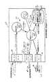
図1は、全体の略図で参照番号10は殺菌およびコンタクトレンズ包装の第二回包装を受動的にモニターするための殺菌モニターシステムを図示している。詳細に以下に説明するように、本発明の殺菌モニターシステム10は特に処理殺菌シリアルデータに処理するように形成されており、殺菌経過報告を生成する。
【0015】
図1に示すように、殺菌監視システム10は殺菌制御機器25を有する殺菌チャンバー15から構成され、殺菌チャンバー15は好ましい実施例ではPLCまたは殺菌処理を制御し、殺菌処理データ16およびフォーマット化されたアスキーキャラクターとしてアラームデータ(アラーム条件が存在する場合)を専用プリンター17へ連続して送る専用処理制御装置であり、殺菌処理データ16およびアラームデータは、制御するインターセプティング殺菌モニターノード20は言うまでもなくデータライン16aと既存のコンタクトレンズ生産ライン監視品質管理システム100に接続されるデータライン16bとを経由して専用プリンター17へ連続して送られる。以下に詳述するように、殺菌モニターノード20はアスキー殺菌データを処理し、図23に部分的に示し詳細は以下に述べる殺菌遂行レポートを第二プリンター18で自動的に作成する。既存のコンタクトレンズ生産ライン監視品質管理システム100は、上記の本発明と同じ譲受人に譲渡された発明の名称「品質管理の相関性のためのコンピュータプログラム」の米国係属特許出願08/257,800号に開示されており、その仕様と開示は参考として本出願に含めてある。上記の米国係属特許出願08/257,800号に記述してあるように、既存の監視システムは、各種の製造工程を制御、モニターする複数のプログラム制御可能およびプログラム制御不可能な制御機器から処理制御データを自動的に取得し、そのデータをリアルタイム標示、オフライン技術解析、および品質保証目的のため自動的に処理する。
【0016】
図2は殺菌モニターノード20と殺菌制御装置25に接続される既存の監視システム100のハードウエアー構成を図示しており、この接続は殺菌モニターノードと二つのオペレータターミナル29a,29b(好ましくはダイナターム(Dynaterm)社製)と既存のモニターシステム100との間の通信を支援するアークネットハブ(ARCNET HUB)ネットワーク機器99a,99bを経由して行われている。好ましくは、殺菌モニターノード20は殺菌モニター処理を実行するための以下のモジュールを有する33MHzのインテル486コンピュータシステムを含むこと、すなわち以下のモジュールとは、殺菌通信モジュールと処理50、殺菌サーバーモジュールと処理60、タイムサーバー70、およびファイルサーバー80である。これらのモジュールはそれぞれ以下に詳述している。
【0017】
手短に言えば、監視システム100は、殺菌監視ノードと、上記の本発明と同じ譲受人に譲渡された発明の名称「品質管理の相関性のためのコンピュータプログラム」の米国係属特許出願08/257,654号およびその仕様と開示は参考として本出願に含めてある同特許に開示されているような、各種のコンタクトレンズ製造処理を制御する少なくとも7台のプログラム制御可能なロジック制御装置とから制御パラメータデータを得る。これらの製造処理は以下の事柄を含む。即ち、PLC31による制御で、射出成型した表曲面レンズ金型のキャリアパレットへの移動、PLC32による制御で、射出成型した裏曲面レンズ金型のキャリアパレットへの移動、PLC33による制御で、モノマー充填およびコンタクトレンズ金型組立操作、PLC34による制御で、前養生、UV養生、およびレンズ金型分離、PLC35による制御で、成型されたコンタクトレンズを含む前曲面金型半分をコンタクトレンズの水和のための水和チャンバーへの移動、PLC36による制御で、自動レンズ検査ステーションに組み込まれた自動視覚システムにより決定されるように合格不合格結果から成るコンタクトレンズ検査データの作成を含む後水和操作、およびPLC37による制御で、回転インデックス(包装)ダイヤル(図示されず)について発生する水溶液の交換、塩分充填、包装箔ヒートシール等の処理を含むレンズ包装処理の一次コンタクトレンズ包装とレンズ包装取りまとめの局面。八番目のPLCは多分二次包装の様々な局面の制御の提供になり、二次包装には殺菌チャンバーから二次包装領域への包装の移送が含まれ、そこでは本発明と同じ譲受人に譲渡された発明の名称「殺菌および二次包装のための機器と方法」の米国係属特許出願08/257,788号に記述され、その開示は参考として本出願に組み込まれているように、ブリスター包装媒体にラベルが貼付されブリスター包装媒体は二次包装カートンに密封される。二次包装は、手短に言うと、バーコード化されたロット番号を印刷しカートンに張り付け、度数と使用期限をカートンに印刷し、ブリスター包装をカートンに挿入しカートンのフラップをのり付け密封し、ロット番号の確認、度数と使用期限の確認、カートンの計量、カートンの箱詰め密封箱へのラベル貼付、そしてパレットへの箱の積載完了とパレットラベルの貼付の段階を含む。
【0018】
好ましい実施例では、各PLC31−38はTIシステム545(TexasInstruments)で、バックプレーンを横切るかまたはシリアルリンク(図示されず)によりそれぞれのPLCと通信するためTI386ATM コプロセッサーを含んでいるかも知れない。各PLCがデータブロックを記憶し更新するためにそれ自身記憶装置と番地指定機能を有していることは分かっている。
図2に示すように、他のプログラム制御可能機器制御装置、たとえばユーシン社(Yushin Corp.)製の制御装置はコンタクトレンズ製作ラインに配備され、それぞれ6秒毎に8個の割合で表曲面レンズ金型を製作する表曲面成型機39a、同じ割合で裏曲面レンズ金型を製作する裏曲面成型機39b、および製造されたコンタクトレンズを検査し包装するコンタクトレンズ包装を製作する一次包装機39cを制御する。もう一つの機器制御装置39dは一次包装以前にコンタクトレンズを自動的に検査する視覚システム(図示されず)を制御する。
【0019】
さらにまた、図2では、既存の監視制御システム(制御システム)100は5種類の処理ノードを含み、そのうちデータ取得ノード205は通信線41およびタイウエイ(Tiway)アダプターカード42により上記の8個のプログラム制御可能ロジック制御装置(PLCs)の各々と通信し、また3個の成型機および視覚検査機の機器制御装置と、専用非同期シリアルライン43a,b,c,およびdによりこれらの機械を接続している8−チャネルシリアルカード44により通信し;リレーショナルデータベースノード210はリレーショナルデータベースソフトウエアーを動かし、製作記録と長期のデータの沿革から成るオフラインデータ記憶装置のために提供されている少なくとも3個の200MBハードディスクを含み;分析および経路指定ノード220は、生データのデータ収集と処理を8個のPLCから始めるために使用されるソフトウエアーの大部分を含み、かつ「リアルタイムデータベース」を維持する。分析および経路指定ノード220は以下のようなモジュールから構成される。即ち、ユーザが定義した論理的なグループまたはデータセット内にデータを記憶し、データセット上に統計と(オプションの)アラームを作成でき、そして統計的制御や他の表示装置を支援する統計サーバー225;PLC、成型機、および視覚検査機からの全てのデータ取得を調整するポーラー226、統計サーバーに対するコンパニオンモジュールであり、かつ統計サーバーに能動的表示装置を支援するために必要な統計的機能を実施させるC−言語制御サーバー228、および、定義した条件に従って動かされる作業セル警報、警告、および例外事項を扱い維持する警報制御サーバー229である。
【0020】
監視制御システム100は、さらにロット情報エントリーおよびロット変更を支援し、かつ以下に述べるようにコンタクトレンズロット追跡再調停を実施するために、モジュール90を含む生産ラインのオペレータにグラフや表示を提供する、4個乃至それ以上の同一に形状化されたオペレータステーション230と、データがライン上になくなった後、即ち、ラインの所定の作業が終わった後のリレーショナルデータベースノードに収集されたデータの分析を提供するオフライン分析ノード240を含む。図2に示すように、アークネットインターフェースカード201,211,221,231,および241のそれぞれに提供されアークネットハブ99aを経由して各種のノード間の通信を支援する。好ましい実施例において、上記のサーバーの全てはマサチューセッツ州リンカーン市にあるファーステックインテグレーション(FASTech Integration)社製の標準セル作業ソフトウエアーである。
【0021】
図2に関して上に述べたように、既存の監視制御装置100用の3種類の入力ソース、即ち、8個のPLCと、射出成型制御装置39a−dと、視覚検査および一次包装機とがあり、さらに殺菌モニターノード20からのデータがある。監視制御システム100が8個のPLCと視覚検査および一次包装機のおのおのから読むイベントブロックとデータブロックの構造は、上記米係属特許出願08/257,800号に詳細に述べられている。加えて、すでに確認済みの米係属特許出願に詳述されているように、生産記録と長期のデータ履歴を記憶するために使われるリレーショナルデータベースが創られる。既存の監視制御システム100はこのデータベースに対するオンラインおよびオフラインアクセスを提供し、処理パラメータ対コンタクトレンズ検査結果の分散図、パレット位置毎の欠陥のヒストグラム、機械によるアラームカウントと期間の頭頂図、積算検査結果の時間プロット、シングルトレンドとしての時間に対してプロットされた測定され計算されたパラメータに限定されないが、これらを含んだ有益なグラフを生成するための機構を含み、これらのグラフで固定時間スケールのトレンド(trend fixed time scale)が利用でき、分,時間,日,週にわたるデータを示すことができる。
【0022】
〔殺菌モニターノード〕
図3の詳細なハードウエアー構成に示すように、殺菌モニターノード20はアークネットインターフェースカード21により既存の監視システム100とつながっており、既存の監視システムとの通信を提供する。8−チャネルシリアルカード22は殺菌制御装置25とメイン殺菌データライン出力から分かれた専用非同期シリアルライン16bからシリアルデータを受け取る(図2)。シリアルポート19はノード20に設けられ、殺菌処理データの完了ラインの通信を行い、殺菌機器の作業が完全か不完全か、データが完全か不完全かあるいは殺菌機器の作業は成功だったかそうでなかったかを示すメッセージを受け取り、そして殺菌機器の作業、エラーログ、およびフェーズファイルレポート作成に関してレポートプリンター18に対するエラーログ情報とフェーズファイル情報を送る。
【0023】
以下に詳細に述べる殺菌モニター処理10は、二個の機能モジュール;殺菌通信モジュール50(「steri comm server 」)と殺菌サーバーモジュール60(「steri server 」)とから構成されている。手短に言うと、殺菌通信モジュール50は殺菌制御装置が生成した文字を8−チャネルシリアルカード22を介して受け取るよう機能する。殺菌サーバーモジュール60は入力の全てを処理し、いろいろのユーザに対するレポートを作成する。たとえば、図3に示すように、殺菌サーバー60は情報を処理、シリアルポート19を介して印刷用殺菌作業レポートを作成し、加えて、殺菌作業レポートファイル、四つの主な殺菌フェーズ(加熱負荷、露出負荷、冷却負荷、およびサイクル完了)に関する殺菌機器フェーズ情報を含む殺菌機器フェーズレポートファイル、および長期磁気ディスク記憶装置23専用のエラー情報のエラーログファイルを作成する。好ましくは、磁気ディスク記憶装置はどんな容量にも簡単に対応でき、少なくとも324MBの容量を持ち、どんなデータ記憶媒体からできていてもよい。後のオフライン分析のためにただちに作用し、処理され、記憶されることが必要なアラームまたは処理データポイントは、全てアークネットインターフェースカード21とアークネットハブ99a(図1)を経由して既存の監視制御装置100へ送られる。殺菌モニター処理10とそこにある殺菌装置処理モジュール50、60の詳細は以下に述べる。
【0024】
〔殺菌制御装置〕
図4は殺菌モニターノード20の内部状態を示す状態略図を図示する。アラームエラーまたは通信タイムアウトエラーの全てを除いて、正常な殺菌作業は、個々に一次(ブリスター)包装されたコンタクトレンズを約1から14,000個の範囲の量から成るバッチが殺菌チャンバーに搭載された後、上記の発明の名称「殺菌および二次包装のための装置と方法」の米係属特許出願08/257,788号に述べてある方法で始まる。
【0025】
図4に示してあるように、正常な殺菌作業は次の5個の引き続いた状態またはフェーズから構成されている、即ち、開始フェーズ161、加熱負荷フェーズ162、露出フェーズ163、冷却負荷フェーズ164、およびサイクル完了フェーズ165である。
【0026】
ノード20が殺菌作業開始状態160、即ち制御装置、殺菌チャンバー、および処理機器を含む殺菌処理ハードウエアーが始動されて動作開始状態になった後、殺菌装置の殺菌チャンバーの温度が処理設定点まで上昇する非常に短い期間、開始フェーズ状態161に移る。加熱負荷フェーズ162の期間に、殺菌チャンバーは、最適圧力状態下で約122.5℃の最大作動温度に到達する。好ましい作動条件では、加熱負荷フェーズ162の期間は約5.5分である。露出フェーズ期間163中に、図4に示すように、一群のレンズは約31分間殺菌状態にさらされる。冷却負荷フェーズ164期間に図4に示すように、温度と圧力が共に下げられることで一群のレンズは約10分間冷やされる。冷却負荷フェーズの後、殺菌装置はサイクル完了フェーズ165に入り、そこでは殺菌処理が正常な条件下で一分以内に殺菌処理を終え、信号167が発せられて殺菌ノードは代替あるいは待機状態159になる。このフェーズの後、今殺菌されたばかりのレンズは殺菌チャンバーから出る位置に置かれ、菌チャンバーは次の一群のコンタクトレンズが殺菌される前に無負荷あるいは休止状態159に置かれる。
【0027】
図4に示され、以下に詳述されるように、異常なイベント(通信タイムアウト168)が開始サイクル、加熱負荷、露出、冷却負荷、およびサイクル完了フェーズの何れかの機関中に発生した場合、そのフェーズは図4、および、それぞれのライン160a,162a,163a,164a,および165aに示されているように中断され、通信タイムアウトの発生、即ち、殺菌ノードはある指定の期間中、好ましい実施例で言えば60秒毎に約1ライン分のデータの割合で、どんなデータも取得しない。タイムアウトを起こしたイベントが修正された場合、信号169が発せられ、殺菌装置モニターノード20は再び殺菌制御装置25からのデータを処理できる。殺菌制御装置25は、タイムアウト状態の期間中はデータのやりとりを行っていたのであるから、以下に述べるアルゴリズム中に作られたロジック信号161b,162b,163b,164b,および165bを介して、殺菌装置モニターノード20に適当な殺菌装置フェーズにおいて殺菌モニター処理を再開させる。
【0028】
〔殺菌モニター処理〕
図1および図3に示されているように、殺菌制御装置25は殺菌装置モニターノード20と一方通行の通信を、RS232シリアルインターフェースのアスキーデータストリームを介して行い、殺菌装置モニターノード20は、アークネットハブ99aを介して既存の監視システム100と双方向の通信を行う。好ましい実施例において、上記の殺菌フェーズの各々の期間中に、殺菌制御装置25は1ラインの殺菌処理読み取りを、好ましくは毎分1回の頻度で送り出す。以下に詳述するようにアラーム条件が存在している場合は、殺菌制御装置25は2秒に1回の頻度で1ライン分のデータを生産し同報通信を行う。
【0029】
図1と図3に関しては、一般に殺菌装置モニター処理を制御するための殺菌装置モニターノード20システムからの、およびそれへのデータの流れを図示する。上記のように、アルゴリズムは殺菌モニターノード20処理モジュールの各々、即ち、殺菌通信サーバー50および殺菌サーバー60により実行され、殺菌装置からの全てのデータ情報出力の受動モニターが可能になり、かつ既存の監視システム100のデータ取得および解析ノードへのデータの通信が可能になる。殺菌制御装置25から生成された全ての情報はデータ取得のため殺菌モニターノード20の殺菌通信サーバー50へ連続して入力される。特に、殺菌制御装置25は殺菌処理の各フェーズの期間に連続データの完全ラインを殺菌通信サーバー50への同報通信を行う。データの各ラインは12の殺菌処理可変データ形式、アラーム条件を記述したアラーム情報データ、またはテキスト形式の多数の文字から構成される。殺菌サーバー60は殺菌通信サーバー50により取得した入力データを処理するデータ処理機能を組み込んで、以下に詳述するように殺菌作業ファイルとレポート75、フェーズファイルとレポート85、エラーログファイル95等を作成する。
【0030】
加えて、以下に詳述するように、次の付加情報、即ち、既存の監視システム100の統計サーバー225から入力されるロット番号情報、および連続通信タイムアウトを検出するために殺菌ノード20のタイムサーバー70により周期的に作成される時間間隔ウエークアップデータは、殺菌サーバーモジュール60へ入力される。殺菌サーバープロセッサー60は、特にリアルタイムの生の殺菌処理測定データは言うまでもなく上記のデータを処理し、以下のものを生成する、即ち、統計サーバー225(図1)による記憶と引き続く報告用の殺菌作業番号、アラーム制御サーバー229(図1)へ入力するためのアラームメッセージ、ハードディスクファイル23(図3)に記憶するための殺菌処理の特定フェーズ毎の情報を含んだ殺菌フェーズファイルデータ、以下にに詳述する殺菌作業レポートを引き続き作成するために磁気ハードディスク記憶装置23へ入力される殺菌作業レポートファイル情報、および既存の監視制御システム100(図1)の制御サーバー228へ入力される殺菌パラメータ値情報である。上記の殺菌データ処理機能の各々は以下に詳述する。
【0031】
〔殺菌通信処理〕
セル作業システムは、データを受け取ったとき殺菌通信サーバー50を実行するように構成される。図5(a)と図5(b)殺菌通信データ取得処理50を図示している。セル作業殺菌通信サーバー50の最初のステップは、ステップ110として示してあるように、シリアルポートハードウエアーを初期化することである。次に、ステップ113でシリアルポートが通信用に開かれ入力データバッファー(図示されず)がフラッシュされる。次に、ステップ115では、「ライン取得」機能は殺菌制御装置から1ライン分のシリアルデータを一度に1文字取得するために、無限ループにより呼び出される。特に、図5(b)に示してあるように、最初のステップ124で現在の文字カウントが0に初期化される。次のステップ126で文字カウントが入力バッファー(図示されず)のサイズと比較される。文字カウントが入力バッファーのサイズより大きい場合は、エラーメッセージがステップ127で印刷され、文字処理のために戻されない(ステップ128)。文字カウントが入力バッファーのサイズより小さい限り、段階131と133が実行され、それぞれ次の文字が検索され(ステップ131)、文字がファイル文字の最後であるかどうかを確認するためにその文字がファイル文字と比較される(ステップ133)。その文字がファイル文字の最後でなければ、その文字はステップ135で入力バッファーにセイブされ、文字カウントはステップ138で増加し、その文字がステップ140でライン文字の最後であったかどうかの確認がおこなわれる。その文字がライン文字の最後であれば、処理は入力ライン(ステップ141)の文字数を戻し、そのラインのデータは殺菌サーバーのメイルボックス、即ち図5(a)に示されるようにステップ155でバッファー位置へ送られる。現在の文字がファイル文字の最後であると決まれば、これは重大なエラーが発生したことを示している。これはシリアルラインが断線して再び接続されたときに発生するかも知れない。それゆえに、ステップ133で現在の文字がファイル文字の最後であると決まった場合、図5(b)のステップで直列機器は閉じ、再開し、そして初期化される。ステップ145において、シリアルポートが開いたときエラーが発生したかどうかについての決定が行われる。エラーが発生していない場合、文字は処理のために戻されない(ステップ146)。エラーが発生している場合、エラーメッセージがステップ149で印刷され殺菌通信処理60はステップ152でアボートする。
【0032】
〔殺菌サーバー処理〕
図6は、エレメント250として示されている殺菌サーバーQNXメイルボックスシステムから構成される殺菌サーバー処理60の主な機能ブロックを図示する。QNXメイルボックスシステムは、ノードのための第一次的メッセージ経路指定エンジンで、殺菌ノード20における各サーバーはコマンドまたはデータメッセージを受け入れて送るメイルボックスを有する。メッセージのソースにより、殺菌サーバー処理60は図6に示され、かつ以下にさらに詳しく説明する三つの機能の「コマンド開始機能」(startCmdFunc)260、「メイルボックスからの殺菌データ取得機能」(getSteriDataFromMbx )260、および「コマンド呼び起こし機能」(wakeUpCmdFunc )280の何れかを実行する。
【0033】
セル作業システムは、それが開始されると、殺菌サーバー処理60開始のコマンドを受け取るとコマンド開始機能260を実行するように構成される。この機能は、殺菌サーバー60とそこの内部変数が初期化され全てのQNX通信メイルボックス(図示されず)が立ち上げられることを確認する。加えて、エントリーエラーログファイル95(図3)に置かれてシステムが開始し、所定の時刻にタイムサーバー70からの今後のウエークアップメッセージが要求されていることを示す。
【0034】
セルワークシステムは、殺菌通信処理50からの完全ラインのデータから成るメッセージが殺菌サーバーメイルボックスに現われるときは、いつでも「メイルボックスからの殺菌データ取得機能」(getSteriDataFromMbx )機能ブロック270の呼び出しが実行されるように構成される。「メイルボックスからの殺菌データ取得機能」(getSteriDataFromMbx )機能ブロック270は、メイルボックスからのメッセージをローカル殺菌サーバー入力バッファー(図示されず)にコピーし、そのメッセージの処理を開始するように働く。加えて、正しいメッセージラインの終りが存在するかどうかを決めるためのチェックが行われる。「メイルボックスからの殺菌データ取得機能」(getSteriDataFromMbx )機能ブロック270は、正しいメッセージラインの終りが存在する場合のみ、殺菌モニターから送られた殺菌データ情報ラインの性質を決めるために「ライン特徴付け」(characterizeLine)アルゴリズム300を呼び出す。以下に述べるように、殺菌データ情報ラインの性質を決めること、およびこのデータの処理には、以下の機能の1乃至は2個が含まれる。即ち、ブロック440として示されている「テキスト評価ライン」(evalTextline)、ブロック405として示されている「処理データライン(processDataLine )、ブロック500として示されている「処理アラームライン」(processAlarmLine)、ブロック320として示されている「オープン殺菌作業レポート」(openSteriRunReport)、およびブロック550として示されている「更新アラーム状態」(updateAlarmStatus) である。
【0035】
図7に示されているように、「ライン特徴付け」(characterizeLine)アルゴリズム300の最初のステップ302は、起こり得る通信タイムアウトの検出に役立てるために現在の時刻を記録することである。次のステップ304はラインのデータを送り、1つのラインのデータとしてラインの特徴づけと抵触できた殺菌モニターにより送られた見せかけのプリンター制御文字を取り除く。次に、ステップ306で、そのラインに何か印刷可能な文字が存在したかどうか、また殺菌装置作業レポートファイル85が開いていたかどうかが決定される。そのラインに印刷可能な文字が存在し、殺菌装置作業レポートファイルが開かれていなかった場合、「オープン殺菌作業レポート」(openSteriRunReport)("steri run report")ファイルアルゴリズムがステップ320で実行される。殺菌装置作業レポートを開く手順は図20に示されており、冗長チェックとして最初のステップ322で殺菌装置作業レポートファイル85がすでに開いているかどうかが決定される。殺菌装置作業レポートファイルが開かれている場合、処理は「ライン特徴付け」(characterizeLine)処理のステップ308へ戻る(図7)。ファイルが開かれていない場合、ステップ330で殺菌装置作業レポートファイルが開く前に以下に示すステップが実施される。即ち、先ずステップ324で、殺菌装置の各フェーズの各変数に対する最少、最大値が初期化される。それから、ステップ326では、以下に詳細に述べるフェーズ期間を後で計算するために、フェーズ毎に退避した開始と終了時刻が初期化される。次にステップ328で、初期作業レポートファイルが示されているように現在の日時、「date time RPT 」から構成されるデフォルト名で立ち上げられる。ステップ330では、作業レポートファイルが開かれる。レポートファイルを開くとエラーが発生することがステップ332で確認された場合、ステップ334では、好ましい実施例では再試行ファイルが立ち上げられ15分毎に開かれ、そしてステップ336でエラーはログレポートファイルに記録される。段階332ではレポートファイルを開いたときエラーが発生しなかった場合、以前に入ったロット番号を統計サーバーからこの処理へ送るように要求され、この処理はライン特徴付けアルゴリズムへ戻る(図7)。
【0036】
殺菌装置作業レポートファイルが図7ですでに開かれている場合、通信タイムアウト検出はステップ308で可能である。そのアルゴリズムはその場合、ステップ310においてラインは次の形式の時間記号で始まる。
hh:mm:ss(hours,minutes,seconds)
【0037】
そのラインがそのような時間記号で始まった場合、processDataLine アルゴリズムは、ステップ405で実施されデータラインが殺菌装置フェーズデータの12個の変数を含んだ処理変数データを含むことを示している。さもなければ、ステップ312で、アラーム条件が存在するかどうかについての決定が行われる。アラーム条件が存在する場合、preoessAlarmLineアルゴリズムはアラームデータを処理し既存の監視システム100のアラーム制御サーバーを更新するため、ステップ500で実施される。データラインが本質的にテキストどおりであれば、evalTextLineアルゴリズムがテキストデータを処理するために実施される。入力ラインの処理が完了しているときは常にupdateAlarmStatus 処理がステップ550で呼び出され、アラーム状態が変更したかどうかをチェックする。
【0038】
図8はデータラインからの殺菌フェーズデータの12個の変数を処理するためのprocessDataLine アルゴリズム405を示す。ステップ407でラインから残っている他の全ての文字を取り去った後、データラインはステップ409で殺菌作業レポートへ加えられる。次に、getDataLinetime アルゴリズムはステップ410で実施され、5個の殺菌フェーズの各々に対して前回の殺菌フェーズのフェーズ停止時刻に加えて現在の動作フェーズの開始時刻が適当なフェーズファイルに記録されていることを確認する。次にステップ412で現在のデータラインの12個の処理可変値が隔離されテキストとして保管される。それから、convertAndDoMinMaxアルゴリズムが殺菌処理読み取りの各々をテキスト形式から浮動少数点形式へ変換し、現在の殺菌フェーズに対して12個変数の各々に対する最大最小値を更新するためステップ420で呼び出される。ステップ425で、フェーズファイルの変数を更新する時機かどうかを決定する。更新しない場合は、処理はステップ427で示したようにcharacterizeLineアルゴリズムへ戻る。変数を更新する時機ならば、ステップ430でメッセージは定式化され既存の監視制御システム100の制御サーバー228へ送られ、12個の浮動処理変数が表示、傾向分析、および上記の米国係属特許出願08/257,800に詳しく述べているような方法で技術データベースに含めることに利用できるようにする。それからステップ435で現在の殺菌装置フェーズが加熱負荷、露出、サイクル完了、または冷却負荷フェーズにあるかどうかが決定される。殺菌装置がこれらの3つのフェーズの1つにある場合、makePhaseFileEntry処理がステップ440で呼び出される。殺菌装置がこれらの3つのフェーズの1つにない場合、処理は呼び出しcharacterizeLineアルゴリズム280へ戻る。
【0039】
図9に示すように、makePhaseFileEntry処理440は処理データラインアルゴリズム405から呼び出され、エントリー用処理変数情報を対応フェーズファイルのラインとして書式化する。好ましい実施例においては、4個の主な殺菌フェーズの各々に対してディスク上に1つの別々のフェーズファイルがある。新しいエントリーが作られると、それは適当なフェーズファイルの最後に次のように加えられる。即ち、先ずステップ445において処理データが殺菌装置の動作の最初から得られたものかどうかが決められる。そうでない場合は、その処理はステップ445でprocessDataLine アルゴリズムへ戻る。現在のフェーズが、開始サイクルが始まった場合、以下の情報はライン形式で収集される。即ち、ステップ448において現在のロット番号、ステップ451において殺菌装置の作業番号、ステップ452において日付、ステップ454において時間、ステップ456においてアラーム条件は現在存在するかどうかを伝える表示、およびステップ458においては現在の殺菌装置の作業に対する現在の12個の処理値である。最後に、ステップ460においてはそのライン全体が現在のフェーズファイルへ書き込まれる。
【0040】
図32は、殺菌フェーズ情報を記憶するための上記のフェーズファイル876のエントリーを示す。図32の表における各行はフェーズファイルにおける1エントリーを表わす。ロット番号は監視制御装置のオペレータステーション230(図1)のオペレータにより入力され、「モード」エントリーは殺菌制御装置がその時点でアラームを表示したかどうかを指示する単一文字である。
【0041】
図7に示してあるように、処理がcharacterizeLineアルゴリズムへ戻ったとき、もし殺菌制御装置から得たデータがアラームデータでも処理変数データでもない場合、evalTextLineがステップ450で呼び出されテキストラインを処理する。
【0042】
図10と図11は、入力データラインからのテキストデータを処理するためのevaluateTextline処理450を示す。評価テキストライン処理の最初のステップ461では残っているプリンター制御文字の全てをラインから取り除き、ステップ462ではラインを殺菌作業レポートへ加える。ステップ463ではテキストが殺菌装置の動作の開始を指示しているかどうかを決定する。もし指示していることがわかれば、StartOfRunEvent 手順がステップ465で呼び出され、図12に示すように以下のステップを実行する。即ち、先ずステップ467でエラーログ95(図3)へのエントリーが行われて殺菌装置の動作が始まったことを示す。それからステップ468では、フラッグが設定されて現在の動作が最初(殺菌装置動作の開始)から始まったことを示し、そしてステップ469で現状は動作状態の開始であることを示す。次に図12のステップ470で殺菌装置現状は動作開始であり、次のデータラインを特徴づけるために処理が戻るというメッセージが既存の監視システムの制御サーバーへ送られる(図7)。
【0043】
図10において、テキストが殺菌装置動作の開始をステップ463で示していなかった場合、ステップ464でテキストが開始フェーズの始まりを指示するかどうかの決定が行われる。テキストが殺菌装置動作の開始フェーズを示した場合、doStartPhaseEvent 手順がステップ465で呼び出され現状は殺菌開始フェーズであるというフラッグを設定し、次のデータラインを特徴づけるために処理が戻る前に現状は殺菌装置開始フェーズ状態であるというメッセージを既存の監視システムの制御サーバーへ送る(ステップ550、図7)。
【0044】
テキストが殺菌装置動作の開始フェーズをステップ464で示さなかった場合、ステップ471でテキストが殺菌装置加熱負荷フェーズの始まりを指示するかどうかの決定がなされる。テキストが殺菌装置加熱負荷フェーズの始まりを示した場合、doHeatLoadPhaseEvent手順がステップ472で呼び出され、現状は殺菌加熱負荷フェーズの始まりであるというフラッグを設定し、殺菌装置の現状は加熱負荷フェーズであるというメッセージを既存の監視システムの制御サーバーへ送る。加えて、HeatLoadフェーズファイルがそこへデータを書き込むために、開かれ、手順は次のデータラインを特徴づけるために戻る。
【0045】
ステップ471でテキストが加熱負荷フェーズの始まりを指示しなかった場合、ステップ473でテキストが殺菌装置露出フェーズの始まりを指示するかどうかの決定が行われる。テキストが殺菌装置露出フェーズの始まりを指示した場合、doExposurePhaseEvent手順がステップ474で呼び出され、現状は殺菌装置露出フェーズの始まりであるというフラッグを設定し、現状は殺菌装置露出フェーズであるというメッセージを既存の監視システムの制御サーバーへ送る。加えて、次のデータラインを特徴づけるために処理が戻る前に、加熱負荷フェーズファイルは閉ざされ、露出フェーズファイルがそこへデータを書き込むために開かれる。
【0046】
テキストが殺菌装置露出フェーズの始まりをステップ473で指示しなかった場合、ステップ475でテキストが殺菌装置サイクル完了フェーズの始まりを指示するかどうかの決定が行われる。テキストが殺菌装置サイクル完了フェーズの始まりを指示する場合は、doCycComplPhaseEvent手順がステップ478で呼び出され、現状は殺菌装置サイクル完了フェーズであるというフラッグを設定し、現在の殺菌装置の状態が加熱負荷フェーズであるというメッセージを既存の監視システムの制御サーバーへ送る。加えて、次のデータラインを特徴づけるために、処理が戻る前に、冷却負荷フェーズファイルは閉ざされサイクル完了フェーズファイルがそこへデータを書き込むために開かれる。それから、次のデータラインを特徴付けるために処理は図7のステップ550へ戻る。
【0047】
テキストがステップ477で殺菌サイクル完了フェーズの始まりを指示しなかった場合、ステップ479でテキストが殺菌装置動作の終わりを指示するかどうかの決定が行われる。もしテキストが殺菌装置動作の終わりを指示する場合は、doEndOfRunEvent 手順がステップ480で呼び出され、図13に示してあるように以下のステップを実行する。先ず、図13のステップ481で殺菌作業が終わったというエントリーがエラーログに作られる。それから、ステップ482で現状は殺菌装置動作を示すフラッグが設定される。次に図13のステップ483でサイクル完了フェーズファイルは閉ざされる。ステップ484では、最も最近のデータラインの時刻がサイクル完了フェーズの停止時刻として保管される。ステップ485では、finishSteriRunReport手順が呼び出され、以下に詳細に述べるように殺菌作業レポートを作成する。doEndOfRunCleanupsd として示される他の手順がステップ486で実行され、テキストライン処理を終了し以下に詳細に述べるように殺菌作業レポートを印刷する。最後に、ステップ487では、次の殺菌作業が何時始まるか分からないので、通信タイムアウト検出ができない。
【0048】
図10に戻って、もしテキストがステップ479で殺菌装置の動作の終わりを指示しなかった場合、図11のステップ488で現在のテキストラインが日付を指示するかどうかが決められる。もし現在のテキストラインが日付を指示する場合は、日はステップ489で保管され、処理は戻りテキストラインの手順を評価する。もし現在のラインが日を指示しない場合は、ステップ490で現在のテキストラインがサイクルカウントを含むかどうかを決める。現在のテキストラインがサイクルカウントを含まない場合は、カウントはステップ491で保管され、殺菌作業番号を作り、殺菌番号を既存の監視システムの制御サーバーへ送るためにmakeSteriRunNumber手順がステップ492で呼び出される。好ましい実施例では、殺菌作業番号が、日,殺菌番号,および殺菌装置サイクルカウントの組み合わせとしてまとめられ、YP1NNNNの形を取る。ここでYはその年の最後の数字、P1は生産ラインの殺菌装置番号、そしてNNNNは殺菌装置のサイクルカウントである。殺菌作業番号が得られたら、処理はライン特徴付けアルゴリズムへ戻る。
【0049】
現在のラインがサイクルカウントを含まない場合は、ステップ494として示されるようにラインについては何も行われないで、処理は呼び出しライン特徴付けアルゴリズムへ戻る(ステップ550、図7)。
【0050】
図14はシリアルデータラインからのアラームデータを処理するためのprocessAlarmLineアルゴリズム500を示す。ステップ502においてラインから他に残っているプリンター制御文字を全て取り除いた後、既知のアラームフレーズのリストをステップ505で探し既知のアラーム条件が存在するかどうかを指示する。以下の表1と表2は各種のアラームフレーズとアラームコードデータを示す。
殺菌制御装置からのアラームテキスト アラームコード
クリーン蒸気低 1
冷却水低 2
圧縮空気低 3
サイクル打切り 4
ドア閉まらず 5
ドア密封せず 6
ファン故障 7
高温 8
高水位 9
低温 10
圧力超過 11
プラント蒸気低 12
プワー不良 13
圧力センサーエラー 14
PT隔離 15
SAM故障 16
蒸気故障 17
温度センサーエラー 18
圧力下 19
未知アラーム:このコードは認識されて 999
いないアラームテキストがある場合
に使用する。
殺菌モニターサーバーが検出した条件 アラームコード
殺菌制御装置の通信タイムアウト 01
【0051】
アラーム条件が未知の場合、すなわち、ステップ507で相手がアラームデータフレーズとアラームデータフレーズテーブルの間に見つからない場合、未知のアラームが受信されたこと、能動アラーム条件が記録されることがステップ508で既存の監視システムのアラーム制御サーバーに伝えられる。そして処理はステップ515に進みアラームラインを殺菌作業レポートへ加える。既知のアラーム条件が存在する場合、すなわちステップ507で相手がアラームデータフレーズとアラームデータフレーズテーブルの間に見つかる場合、ステップ508でアラームがうまく動作するかどうかを示す。指示計がアラームがうまく動作することを示した場合、それがステップ511で記録され、ステップ515でアラームラインは殺菌作業レポートへ加えられる。指示計がアラームがうまく動作することを示さない場合は、ステップ513でアラーム条件が発生したことを既存の監視システムのアラーム制御サーバーへ伝え、能動アラーム条件が存在することが記録される。最後に、ステップ515でアラームラインが殺菌作業レポートへ加えられ、処理は呼び出しcharacterizeLineアルゴリズムへ戻る。
【0052】
上記のように、characterizeLineアルゴリズムを示す図7の観点から、ラインが特徴付けられ、処理変数データ、アラームデータ、またはテキスト形式のデータ情報が処理された後、アラーム状態はupdateAlarmStatus 処理をステップ550で呼び出すことにより更新される。図15はupdateAlarmStatus 機能を詳しく図示する。ステップ552として示される最初のステップは、もし何かアラームを指示している場合、殺菌器制御装置から支給されるパラメータが現在活動状態にあり、かつ上記のように2秒毎にデータラインを送りつつあることを決める。その場合、ステップ554でアラームをクリアーするに十分な時間があるかどうかあるいは現在活動中のアラームを強制的にクリアーすべきかどうかを決める。もしアラームをクリアーするのに十分な時間が経過していない場合、即ち最後の殺菌器データエントリーとその前のデータエントリーの間のアラーム条件を強制的にクリアーすべきであることを指示している時間が2秒である場合、ステップ556で現在の殺菌器のアラーム状態が設定され、殺菌アラームは活動していないことを指示する。アラームをクリアーする十分な時間がある場合、即ち最後の殺菌器データエントリーとその前のデータエントリーの間のアラーム条件を強制的にクリアーすべきでないことを指示している時間が2秒以上ある場合、ステップ559で通信タイムアウトアラームが活動しているかどうか、および最近のデータが入力されているかどうかが決定される。上記のように、データが1分以上の間隔で受け取られた場合、たとえばシリアルデータラインが一時的に切り離された場合、通信タイムアウトが発生する。通信タイムアウトアラームが活動しておりかつ最近のデータが入力されている場合は、ステップ561で現在の通信アラーム状態は強制的に通信アラームは活動していないことを指示し、そのような指示を提供するよう設定される。通信タイムアウトアラームが活動しておらずかつ最近のデータが入力されていない場合、たとえば殺菌作業の終わりである場合は、ステップ563で全てのアラームがクリアーされるかどうかが決められる。全てのアラームが現在クリアーされている場合は、ステップ565でメッセージが既存の監視システムのアラーム制御サーバーへ送られ、全ての殺菌器関連アラームをリセットする。そうでないと、全てのアラームがクリアーされないとプログラムは呼び出しライン特徴付け処理へ戻る。
【0053】
図13へ戻って、ステップ485でfinishSteriRunReport485は殺菌器動作が検出されたとき呼び出される。図16に示されているように、finishSteriRunReport手順の最初のステップ610は現在の動作が最初(殺菌器の動作の開始)から始まったことを示すフラッグが、上記のようにステップ468,図12に関して設定されていたかどうかを決める為にある。サイクルが殺菌作業の最初から始まっていることを示すフラッグが設定されない場合、ステップ612でラインが1つデータが不完全であることを示す殺菌作業レポートへ加えられ、ステップ614でデータが不完全であることを示すエラーログにエントリーが作られる。そして処理はステップ617に対して再開される。サイクルが殺菌作業の最初から始まっていることを示すフラッグが設定されている場合、ステップ611で殺菌作業番号が殺菌作業レポートへ加えられる。次に、ステップ613で4つの主な殺菌フェーズのどれかが現在の動作に欠けている場合は、データが不完全であることを示す殺菌作業レポートへ1ラインが加えられ(ステップ612)、データが不完全であることを示すエラーログに対してエントリーが作られる(ステップ614)。4つの主な殺菌フェーズのどれも現在の動作に欠けていない場合は、ステップ615で、データが完全であることを示す殺菌作業レポートへ1ライン追加される。図16にステップ617で示される次のステップは、殺菌制御装置が図14のステップ511で上に述べたように有効サイクルを指示する成功動作アラームを発したかどうかを決める為にある。有効サイクルを指示する成功動作アラームが殺菌制御装置により作られている場合、ステップ619で動作が成功であったことを示す殺菌作業レポートファイルへ1ライン加えられる。有効サイクルを指示する成功動作アラームが殺菌制御装置により作られていない場合、ステップ621で動作が不成功であったことを示す殺菌作業レポートファイルへ1ライン加えられる。最後に、ステップ630では、主な殺菌フェーズの各々に対する期間を殺菌作業レポートファイルへ加える手順が呼び出され、ステップ640では、主な殺菌フェーズの各々に対する処理変数の最小最大値を殺菌作業レポートファイルへ加える手順が呼び出される。
【0054】
finishSteriRunReport手順のaddDurations手順630は、図18のステップ631として示すように殺菌作業レポートのフェーズ期間ヘッダーラインを加えることにより始まる。次に、ステップ632に示してあるように、ポインターが4つの主なフェーズの最初に設定される。次のステップはフェーズ期間の印刷を指示する。即ち、ステップ633ではフェーズ期間に対するラベルが得られ、ステップ634ではopenSteriRunReportアルゴリズムのステップ326で得られた保存済みのフェーズ開始および終了時刻を使ってフェーズ期間が計算される(図20)。次に、ステップ635で4つの主な殺菌器フェーズの全てに対するフェーズ期間値が処理されたかどうかについての決定がされる。4つの主な殺菌器フェーズの全てに対するフェーズ期間値が処理された場合は、ステップ636で4つの主な殺菌器フェーズの各々に対する計算済みのフェーズ期間を持った結果ラインが殺菌作業レポートファイルへ加えられ、プログラムはfinishSteriRunReport手順のステップ640へ戻る(図16)。4つの主な殺菌器フェーズの全てに対するフェーズ期間値が処理されていない場合は、ステップ633とステップ634が図18のステップ638で示されているようにポインターで指定された各成功フェーズに対して繰り返される。
【0055】
finishSteriRunReport手順で呼び出されたaddMinMax 手順図19のステップ641として示されたように、最小/最大ヘッダーラインを殺菌作業レポートファイルへ加えることで開始する。次に、ステップ642に示されているように、12個の変数名をふくむラインが動作レポートファイルへ加えられる。それから、ポインターがステップ643aで示されているように、4つの主なフェーズの最初に設定される。各フェーズ毎に、最小と最大読みだしのそれぞれに対して1つずつのラインがファイルへ加えられる。次のステップは最小最大読みだしの印刷を指示する。即ち、ステップ644ではフェーズの最小値に対するラベルはファイルの最初のラインの始まりに加えられ、ステップ645ではこのフェーズの変数の12個の最小値を含むラインが加えられ、ステップ646では最小値の結果ラインス殺菌作業レポートファイルへ加えられ、ステップ647ではフェーズの最大値に対するラベルがファイルの第二ラインの最初に加えられ、ステップ648ではこのフェーズの変数の12個の最大値を含むラインが加えられ、ステップ649では最大値の結果ラインが殺菌作業レポートファイルへ加えられる。次に、ステップ650では、殺菌器の全ての4つの主なフェーズに対する最小最大値が殺菌作業レポートファイルへ加えられているかどうかが決められる。殺菌器の全ての4つの主なフェーズに対する最小最大値が印刷されている場合は、処理は殺菌器フェーズ期間の印刷のためのdoEndofRunEvent 手順のステップ486へ戻る。殺菌器の全ての4つの主なフェーズに対する最小最大値が印刷されるまで、ステップ644からステップ649は、図19のステップ643bに示されているように、ポインターが指定した各フェーズに対して繰り返される。
【0056】
最後に、addDurationsおよびaddMinMax値を実行した後、プログラムはdoEndofRunEvent手順480へ戻り、そこでは図13に示されているようにdoEndOfRunCleanup手順がステップ486で実行される。
【0057】
図17はdoEndofRunCleanup 手順486を図示している。ステップ651が示すように、この手順は図21のステップ660からステップ669について以下に詳細に述べるように、殺菌作業レポートを閉めて印刷するためのcloseAndPrintRunReport手順を実行する。さらに、図17のdoEndOfRunCleanup 手順は、ステップ652で全ての内部変数をno-run-in-progress条件へ初期化し、ステップ653で図15のステップ552からステップ565に関して述べるように更新アラーム状態手順を呼び出し、ステップ654でエラーログを閉め、そして、ステップ655で殺菌装置が現在スタンバイまたは待ち状態にあることを制御サーバーに伝える。最後に、プログラムは図13のdoEndofRunEvent 手順のステップ487へ戻る。
【0058】
図21に示されているように、殺菌作業レポートを閉めて印刷するために、最初のステップ660は動作レポートファイルを閉める。上記のように、殺菌サイクルは不完全であると決定された場合、殺菌作業番号は不完全な動作に対しては得られていないかも知れない。従って、ステップ662では、殺菌作業番号がこの動作に対して得られているかどうかが決められる。殺菌作業番号がこの動作に対して得られている場合は、ステップ665で新しい動作レポート名が好ましくは下線とロット番号を従えた殺菌作業番号から成るように構成される。ステップ667では、動作レポートファイルが新しい構成に新しく命名される。最後に、動作レポートファイルはステップ669で印刷される。殺菌作業番号がこの動作に対して得られていなかった場合は、殺菌作業番号が無く、図20のステップ328に関して上に述べたように、日と時間から構成されるように初期に割り当てられたデフォルトファイル名で動作レポートファイルがステップ669で印刷されることを指示しているエラーログに、ステップ663でエントリーが置かれる。動作レポートファイルがステップ669で印刷された後、処理はdoEndOfRunCleanup 手順486のステップ652へ戻る(図17)。
【0059】
図24に示されているように有効で完全な動作用で、ノード20へ接続したプリンター18で印刷した印刷済みの殺菌作業レポート800は、以下のものから構成される。即ち、ライン810として示されるように、下線とロット番号を従えた殺菌作業番号から構成される更新された殺菌作業レポートファイル名;ライン815として示される見出しデータ、ライン816a、ライン816bをそれぞれ含む殺菌作業が始まる日と時間;殺菌装置、ライン817a、817bをそれぞれ識別する名前と番号;殺菌作業、ライン818を独特な方法で識別するためのサイクルカウンター番号;ライン819として示され、露出タイマーが露出フェーズ期間用目標値を示す12個の殺菌装置処理パラメータ;殺菌器制御装置に制御プログラムを示すプログラム822;および殺菌器制御装置25により既存の監視制御装置100と殺菌モニターノード20へ送られるライン825として示された出力データライン用のコラム見出しを示すプログタイム824である。加えて、データライン825の各々は、見出し(header)に記述される12個の信号の各々に対する読みを従えた動作の開始時間を含む。また、以下のものが提供される、即ちライン812として示された殺菌作業番号;V1−V12とラベルされ毎分一度作られる12個の処理可変データ用の可変データライン;ラベルヘッダーライン830を持ったライン835として示されるように4つの主な殺菌フェーズの期間;ヘッダーライン840を使ってライン845として示されるように、4つの主な殺菌フェーズの各々の期間中に殺菌装置変数毎に観測された最小および最大の読み;ライン850として示されている殺菌作業の成功不成功評価;および全てのデータが4つの殺菌フェーズ、即ち現在の動作に対して受け取られた場合、データが不完全であることを示すライン855である。加えて、オペレータまたはエンジニアが署名するためのライン805が殺菌作業レポート中に提供される。アラーム情報(たとえばファンの故障)も殺菌器制御装置により印刷してもよいし、どんなアラームテキストも単独で1つのライン上に印刷される。殺菌器制御装置はアラームテキストを赤で印刷されるプリンター制御コードでアラームテキストを囲む。
【0060】
図示されないが、専用プリンター17(図1)は図24に示されるレポートと同様の殺菌作業レポートをシリアルデータライン16a経由して殺菌器制御装置から直接印刷する。しかし、専用プリンター17が印刷するレポートは殺菌モニターノードにより作成される殺菌器動作レポートに提供されないようにフェーズ期間と最小/最大値の要約、および成功/不成功指示を持たない。
【0061】
図22は、タイムサーバー70(図3)がウエークアップメッセージを殺菌サーバー処理60へ送るときはいつでも実行可能なソフトウエアー機能であるwakeUpCmdFunc処理280を詳細に図示している。図22に示すように、wakeUpCmdFunc処理の最初のステップ281は、将来指定の時刻に他のウエークアップメッセージを殺菌サーバー60へ送るようタイムサーバーに要請するためにある。これは連続した処理ではなくタイムサーバー70がウエークアップメッセージを殺菌サーバーに送るように要請されなければならないことは分かっている。ステップ283とステップ284として示されている次の2つのステップは通信タイムアウトが発生したかどうかを示す為にある。特に、ステップ283において、殺菌サーバーが初期化されるかどうか、タイムアウト検出機能が可能かどうか、そして活動している通信タイムアウトアラームが現在は存在しないことについての決定が行われる。もしこれらの全ての条件が存在しない場合、処理はステップ285で示されるようにCELLworks システムへ戻る。もしこれらの全ての条件が存在する場合、ステップ284において不適当な量の時間、たとえば1分以上の時間がデータの最後を受け取った以後かかったかどうかを決める。このような条件はシリアルデータラインが一時的に不通になった場合に発生する。最後のデータが受け取られた以後の時間量が過大でない場合(1分を越えない)、処理はステップ285で示すようにCELLworks システムへ戻る。最後のデータが受け取られた以後の時間量が過大である場合、ステップ286で通信タイムアウトアラームが活動していることを示す。そして、ステップ287で通信タイムアウトアラームメッセージが既存の監視システムのアラーム制御サーバーへ送られる。加えて、ステップ288では通信タイムアウトアラームエントリーがエラーログに作られる。次にステップ290でendRunReportForTimeout処理が図23に図示されているように呼び出され、次のように詳細に述べられる、即ち先ず最初に殺菌装置動作レポートファイルが現在開いているかどうかについての決定が行われる。殺菌装置動作レポートファイルが現在開いていない場合は、処理はwakeUpCmdFunc 処理のステップ295へ戻る。殺菌装置動作レポートファイルが現在開いている場合は、ステップ292で通信タイムアウトが発生したことを示し、かつステップ293で現在の殺菌作業用の不完全な動作データがあることを示す動作レポートファイルへラインが加えられる。ステップ294では動作データが不完全で処理が図22のwakeUpCmsFunc 処理のステップ295へ戻るエラーログにエントリーが作られる。ステップ295ではdoEndOfRunCleanup 手順が図17について上に述べられているように呼び出される。最後に通信タイムアウト可能機能はステップ296で機能せず、ステップ297で現在開いているフェーズファイルも処理がwakeUpCmdFunc 処理へ戻る前に閉められる。
【0062】
〔ロット追跡および再調停〕
図2に示されているように、生産されるレンズロット番号と度数を生産ラインに沿った4つのオペレータステーション230のどこにおいてもオペレータが入力する。そうすると、ステーションにあるロットの再調停と追跡アルゴリズム90が実行されロット情報記憶装置用に使用期限、レンズ中心厚さ、および他の変数を計算し推薦する。好ましい実施例では、使用期限は入力したシステム日から数えて16ヶ月であるが、月数は変更してもよく、アルゴリズムは熟練したオペレータなら簡単に修正できる。
【0063】
図25の処理フローチャートに示してあるように、オペレータはステップ671として示されているように先ずオペレータの名前とパスワードを入力するように要請され、入力された名前とパスワードはステップ672でデータ分析ノード(図示されず)にある正規の個人名とパスワードのパスワードファイルにより確認される(図示されず)。レンズロット番号のオペレータエントリー、度数値情報、およびオペレータステーションにある現在の日付情報を使って、ロット追跡および再調停アルゴリズム90が実行される。特にステップ673では入力したレンズロット番号が検索され、レンズロット番号のフォーマットが確認される。ロットが歳入のためか試算のためか(「R/T」)を表す数字を含む確認済みのロット番号からロットが歳入のためか試算のためかについての決定がステップ674で行われる。次にステップ675で入力したレンズ度数値が検索され、度数ファクターの有効性が確認される。度数ファクターの有効であるかどうかの決定はステップ676で行われる。有効な度数ファクターが無ければ、オペレータは度数ファクターを有効にするため新しい度数ファクターを入力する(ステップ675)。度数ファクターが有効な場合は、アルゴリズムはルックアップテーブル(図示されず)を使いステップ677で製品コード(「UPC」)とレンズ中心厚さ情報を決める。ステップ678で示すようにロット番号、度数値情報、ロット使用期限、製品コード、生産ラインの前に、かつ、他のエントリーは製品が一次包装に到着するまでどの操作ステーションでも表示してよいことを理解すべきである。加えて、ロット番号、度数値情報、および他のエントリーはロット製品が一次包装に到着するまで変更してもよい。
【0064】
追跡ロット移動、ロット調停、およびロット交換手順を支援するため、1つのオペレータステーションまたは殺菌装置ノードにおけるダイナターム(DynaTerm)表示ステーション29a,bの何れかで表示装置が利用でき、フォーマット化されたフィールドで記憶済み又は以前に入力したロット番号、製品コード、レンズ度数、レンズ中心厚さ、使用期限、製品が歳入のためか試行のためか、ライン上のロットの現在位置は言うまでもなくこれらの情報の表示をオペレータが請求できるようにする。以下にさらに詳しく説明するように、以前に入力済みの情報を表示することに加え、殺菌ノード20の殺菌サーバー60により提供されたように、殺菌作業番号も表示してもよい。図2に示した各オペレータステーションがオペレータの請求を取得し、フォーマット化したフィールドで情報をオペレータに表示するための専用CELLworks プログラムを有することは理解される。
【0065】
〔ロット追跡〕
上記のように、オペレータはロットをラインの次の部分へつぎつぎと配列することができる。ロットが生産ラインに入ったとき、ロット番号情報を表す6個の変数が既存の監視制御システム100の統計サーバーに記憶される。これらの変数はロット番号、UPC、R/T、度数、厚さ、および使用期限で、図26(a)に示されているようにデータ構造を有する。ロットが置かれている製造区域により、ロット用の各データ構造は「0」または「F」で仕分けられ、それぞれライン以前にあるのか、包装以前のライン(射出成型、レンズの製作、養生、金型外し、等)の前にあるかを示す。ロットが一次包装に入ると、図26(a)のデータ構造は「P」で区分けされそのロットは包装中であることを示す。そのロットのレンズはトレー積載領域、殺菌領域、または二次包装領域にあるとき、統計サーバー225は2つの追加変数を図26(a)のデータ構造に記憶し図26(b)に示すように新しいデータ構造を形成する。これらの変数は入力量と損失量で、ロットの再調停中にシステムへ支給される。ロットが殺菌装置の受け台積載領域に入り始めたら、変数は「L」で仕分けられ、そのロットが殺菌装置に入ったら、そのロットのレンズ「S」で仕分けられる。ロットが二次包装に入ると、6個のロット情報変数は「C」で仕分けられ、カートン詰めを指示する。こうして、本発明の特徴はオペレータが特定のロットの動きを追跡する能力となる。
【0066】
図27のデータフローチャートに示してあるように、たとえばライン上で処理中のロット875をそのロットが移動されるべき生産ライン上の位置880のようなデータを入力することによりロットの移動を要請してよい。次に述べる事柄を処理するmoveLot アルゴリズム680が実行される、即ちロット番号881、製品コード882、度数883、レンズ中心の厚さ884、使用期限885、製品は歳入か試行の何れか886、そしてライン887の特定の場所へ入力したレンズの合計とレンズの損失合計888(以下に述べるように)のようなロット情報データは言うまでもなくオペレータが入力したデータである。
【0067】
図28は生産ラインを通してレンズロットの移動を追跡するためのmoveLot アルゴリズム680を図示する。図28のステップ680として示すように、生産ライン上のレンズロットの原始位置が検索される。次にステップ683では、たとえば、ある問題がラインに存在する場合、レンズロット全体よりもむしろ欠陥バッチを取り去るために予防措置としてロットがエントリー以前に殺菌装置15において分割されることになっているときロット番号が変更されるべきかどうかが決められる。ロット番号が変更されない場合、ステップ685でロット番号、製品コード、度数、レンズ中心厚さ、使用期限、および製品が歳入か試行かといったレンズロットとロット情報データが次のライン位置に移され、ライン上のどの位置でレンズロットが動いたかによりそれぞれ標識「P」「L」「S」または「C」で仕分けられる。ロット番号が変更される場合、ステップ687でレンズロット番号はオペレータにより検出されレンズロット番号のフォーマットはステップ689とステップ690で確認される。入力済みのロット番号が有効でない場合、オペレータはロット番号を有効にするため新しい度数ファクターを入力するようになる(ステップ687)。入力済みのロット番号が有効である場合、アルゴリズムはステップ692で上記の識別ロット情報を更新する。
【0068】
〔ロット再調停〕
製品は製造中に紛失または品質保障のため取り除かれるかも知れないという事実のため、二次包装の前にこの製品および紛失または除去の理由を説明することが必要である。ロット再調停とはこれ以降ゾーン1で示す一次包装作業を離れ、これ以降ゾーン2で示す殺菌作業(殺菌受け台搭載)に入る特定のロットの各レンズ、ロットがこれ以降ゾーン3で示す二次包装(即ち殺菌受け台取り外し、カートン詰め、計量チェック、およびラベル貼付)に利用できるときに説明される処理である。特に、図33に図示されているロット再調停シート890が作成される。そのシートは殺菌装置(ライン891)へ入力されるレンズの数と二次包装に利用できるレンズの数(ライン899)を示し、そして言うまでもなく特定のゾーン毎(ライン892、893、894、および895)に失いあるいは取り除かれたレンズの数に等しい差を確認する。既存の監視制御システム100にある「ロット追跡と再調停」アルゴリズムはデータエントリーとロット再調停のための計算を支援する。
【0069】
図29は、一次包装後殺菌装置15へ入力したレンズの分量の報告を必然的に伴うロット再調停処理の開始を図示する。この量をオペレータターミナル230またはダイナターム(DynaTerm)操作卓29a,b(図2)から入力する前に、ロットが一次包装、即ちブリスターパックに包装され殺菌の準備ができた一次包装を終えたかどうかの決定がステップ704で行われる。もし一次包装が終っていなければ、ロットが一次包装を終えるまで入力量は入力できないと言うエラーメッセージがステップ704で表示される(ゾーン1)。もし一次包装が終っていれば、オペレータはオペレータの頭文字と殺菌の準備ができた実際のレンズの量をステップ705で入力することになる。次にステップ706でロット情報が更新されロット番号で新しい変数、入力量に反映される。
【0070】
殺菌作業に入るレンズの量を表す数が入力されると、殺菌から取り除かれるレンズの数(ゾーン2)と二次包装(ゾーン3)領域は、記録され入力されなければならない。図30に示すように、ステップ710とステップ720でオペレータは失った製品の数、製品が失われた特定のゾーン、製品が失われ取り除かれた理由、そして殺菌作業番号を全てオペレータターミナルまたはダイナターム(DynaTerm)操作卓から入力してもよい。この情報は全て殺菌サーバーから入力される特定のロット番号で参照される。この処理はロットが1ゾーンにある間、何回か繰り返される、たとえばロットがそのゾーンにある間にレンズの紛失が複数回発生する。
【0071】
特に、ステップ710で現在のロット位置のゾーン番号は検索され、ゾーン番号が有効かどうかについての確認はステップ713で行われる。ゾーン番号が有効でない場合、オペレータが正しいゾーン番号を入力することになる。ゾーン番号が有効な場合、ステップ716でどのゾーン番号が入力されたかについての決定がなされる。もし現在のロットがゾーン2または3にある場合、オペレータが殺菌作業番号をステップ720で取り除かれたレンズの数をステップ718で入力することになる。取り除かれたレンズの数を入力すると、ステップ723でオペレータステーションまたはダイナターム(DynaTerm)が理由選択リストを表示し、オペレータが生産からレンズ包装が取り除かれた特別の理由をステップ725で入力する。ロット当り複数の殺菌作業があるかも知れないから、1殺菌作業当りいくつかの理由により失われるかも知れない。理由コードとそれらに対する定義を有するルックアップテーブル(図示されず)がオペレータステーションまたはダイナターム(DynaTerm)操作卓の各々に利用できる。以下の表2はレンズが取り除かれた理由のいくつかについて詳細に述べている。
【0072】
理由コード 定義
01 QAのために除去
02 レンズ分散
03 機械的原因による箔裂け
04 箔裂け箔寸法
05 箔にかかる不良度数
06 箔の使用期限の間違い
07 箔上の印刷不鮮明
08 印刷の不整列
09 箔の不整列
10 不整列な穿孔
11 溶液無し
12 低溶液
13 箔上の不良ロット番号
14 シール不完全
15 穿孔裂け
16 シール/包装の吹き飛び
17 正しい位置にバーコードが印刷されず
18 ブラケットにロット番号無し
19 ロット番号バーコードの数字不良
20 UPCバーコードの数字不良
21 無効バーコード(ロット番号)
22 無効バーコード(UPC)
23 不正チェック数字
24 バーコード上の染み
25 バーコード上の穴
26 低級バーコードスキャン確認
27 過剰のり付け
28 タブシール無し
29 タブ不平行
30 カートンのインクよごれ
31 カートン損傷
32 異物
33 カートン詰め器による計量不良
34 ラベル不整列
35 カートン陰影部分に印刷のずれ
36 不正ケースラベル情報
37 ジャムアレー破壊
38 カートン詰め器のジャムによるカートン破壊
39 コンベヤー移送ジャムによるカートン破壊
40 ベルトアレーへのジャムによる破壊
41 ベルトアレー外のジャムによる破壊
42 箔に印刷の無し
43 穿孔無し箔
44 余分なレンズ
60 理由述べ
【0073】
図30のステップ727で、オペレータステーションに表示されたリストからの選択を行うかどうか、オペレータがレンズ取り除きの新しい理由を入力したかどうかについての決定がされる。表示されたリストからの選択を行う場合は、オペレータはステップ731でオペレータの頭文字を入力することになる。オペレータがレンズ取り除きの新しい理由を入力する場合は、オペレータが入力した最大34文字になるかも知れない記述は、ステップ731で頭文字を書き込む前にステップ729で検索される。次のステップ735では上記の図26(b)に示すように描いたデータ構造を持つロット再調停データが更新される。
【0074】
二次包装が完成した後ロット再調停中に行われる最後の動作は、図31の処理フローチャートに示されるようにロットを閉めることである。図31に示すように、オペレータは先ずステップ742でパスワードファイルにより確認されるステップ740として示されたオペレータの名前とパスワードを入力するように要請される。更新されたロット情報データはステップ745で検索され、ロットが前のゾーンをクリアーしたかどうかの決定がステップ747で行われる。ロットが前のゾーンをクリアーしている場合、エラーがステップ749で報告されロットは閉められない。ロットが前のゾーンをクリアーしている場合はマスターロット(または分割ロット)情報はステップ751でオペレータのエントリーにより得られる。それから、ステップ754でロット再調停計算が失ったまたは取り除かれた合計のレンズに対して行われる。次にステップ756では、失われまたは取り除かれたレンズ包装の合計数が、入力されたそれより多いかどうかの決定が行われる。もし前者の合計数が後者のそれよりも多い場合は、エラーメッセージがステップ758で報告される。もし前者の合計数が後者のそれよりも多くない場合は、失われたあるいは取り除かれた総数が入力された総数の1パーセント以上であるかどうかの決定がステップ759で行われる。もし失われたあるいは取り除かれた総数が入力された総数の1パーセント以下であれば、失われたあるいは取り除かれた総数が入力された総数の1パーセントに等しいかそれ以下かの決定がステップ764で行われる。もし入力されたレンズ包装量が出力された量に等しい場合は、そのロットはステップ768で閉められる。もし失われたあるいは取り除かれた総数が入力された総数の1パーセント以下であれば、1パーセント以下の失った総数がステップ769でオペレータへ報告され、オペレータはステップ771で閉め動作を行うことになる。オペレータはステップ771でマスターロット(または分割ロット)閉めを選んだ場合は、マスターロット(マスターロット)はステップ768で閉められる。それから、ロット再調停報告がステップ775で示しているように記憶と印刷用に作成される。
【0075】
本発明はその好ましい実施例に関して特に示され述べられているが、前述および他の形状の変更と詳細は添付したクレームの範囲のみに制限されるべき本発明の精神と範囲から逸脱するものではなくこの技術に習熟している者に理解され、添付したクレームの範囲のみに制限されるべきである。
【0076】
本発明の具体的な実施態様は以下の通りである。
(A) 複数のコンタクトレンズ処理ステーションを有し、更にコンタクトレンズの製造後に複数のコンタクトレンズを殺菌する自動化殺菌ステーションと殺菌後にコンタクトレンズを包装する包装ステーションとを含む、コンタクトレンズを製造する自動化製造ライン用の品質管理システムにおいて、
(a)コンタクトレンズの製造に先立ち、少なくともコンタクトレンズの1バッチを形成するレンズロット毎の関連するロット番号及びレンズ度数を含んだコンタクトレンズ・データを受領する第一の手段と;
(b)コンタクトレンズを製造する処理ステーションで複数の処理制御器をその各々が制御する、1個以上の処理ステーションを制御する複数の処理制御装置と;
(c)前記複数の処理ステーションから前記自動殺菌ステーション及び前記包装ステーションへのレンズロットにより形成された複数のレンズの移動を追跡する手段と;
(d)前記殺菌ステーションで不合格とされたコンタクトレンズの理由コードと共に前記包装ステーションに入力されるレンズ数を表すデータを受領する手段と;
(e)前記殺菌室に入力された所定のレンズロット毎のレンズ総数と前記ロットから殺菌及び包装されたレンズの実数とについての概略レポートであって、コンタクトレンズの各バッチ毎のロット数及びレンズ度数を含んでいる概略レポートを作成する手段とから成るシステム。
(1)レンズロットは複数のレンズバッチから成り、前記殺菌ステーションは前記1バッチ分のコンタクトレンズを同時に殺菌し、殺菌されたバッチ毎に殺菌サイクル動作番号を作る実施態様(A)に記載の品質管理システム。
(2)前記概略レポートは前記殺菌チャンバーへ入力されたレンズの数を殺菌サイクル動作番号毎に前記バッチから包装されたレンズの数に一致させる実施態様1に記載の品質管理システム。
(3)失われあるいは取り除かれた各レンズは理由コードと関連し、前記概略作成手段は殺菌サイクル動作番号を有するレンズ包装取り除きコードを含む実施態様1に記載の品質管理システム。
(4)所定のレンズ度数に対する厚み仕様と製品コードを自動的に計算する手段を含む実施態様1に記載の品質管理システム。
(5)厚み仕様と製品コードを計算する手段はルックアップテーブルを含む実施態様1に記載の品質管理システム。
【0077】
(6)所定のレンズロットに対する満期日を自動的に計算する手段を含む実施態様1に記載の品質管理システム。
(7)前記処理手段は前記生産ライン上の特定のロットの位置を表示する手段を含む実施態様1に記載の品質管理システム。
(B) レンズロットにより形成された複数のコンタクトレンズを製造する自動化コンタクトレンズ製造ライン用の殺菌データ処理システムであって、前記コンタクトレンズ製造ラインがコンタクトレンズの製造後前記レンズロットを殺菌する自動化殺菌ステーションを有し、前記自動化殺菌ステーションが殺菌処理の1フェーズ以上を制御する殺菌剤処理制御装置を有し、前記処理制御装置が前記各殺菌フェーズの間に殺菌処理データを定期的に生成してなるシステムにおいて、
(a)前記殺菌剤処理制御装置から前記殺菌データを受領する手段と;
(b)前記殺菌データを自動的に分析してテキスト情報及び殺菌剤パラメータにし、更に前記テキスト情報及び殺菌剤パラメータを処理して、前記殺菌済レンズロット毎のロット数に関連する殺菌作業レポートを自動的に作成する手段とから成るシステム。
(8)前記処理制御装置はさらにデータの表示と記憶のため前記殺菌装置パラメータ情報を前記自動化コンタクトレンズ製造ラインのデータ取得装置へ運ぶ実施態様(B)に記載の自動化コンタクトレンズ製造ライン用殺菌データ処理システム。
(9)前記処理制御装置はアラーム条件情報を生成し、さらにデータ表示のため前記アラーム条件情報を前記自動化コンタクトレンズ製造ラインのデータ取得装置へ運ぶ実施態様(B)に記載の自動化コンタクトレンズ製造ライン用殺菌データ処理システム。
(10)前記処理手段はさらに前記テキスト情報に基づいた殺菌動作の成功又は失敗および前記殺菌動作レポートに基づいた指示用殺菌制御パラメータ情報を評価するための手段を含む実施態様(B)に記載の自動化コンタクトレンズ製造ライン用殺菌データ処理システム。
【0078】
(11)前記処理手段はさらに完全な1組のデータが現在の殺菌動作用に得られているかどうかを評価するための手段を含む実施態様(B)に記載の自動化コンタクトレンズ製造ライン用殺菌データ処理システム。
(12)前記テキスト情報は前記殺菌処理の現在の操作フェーズを含む実施態様(B)に記載の自動化コンタクトレンズ製造ライン用殺菌データ処理システム。
(13)前記殺菌パラメータ情報は前記殺菌処理の各操作フェーズ中に前記殺菌処理制御装置により作られる複数の分離された処理値を含む実施態様(B)に記載の自動化コンタクトレンズ製造ライン用殺菌データ処理システム。
(14)前記処理手段はさらに前記フェーズ期間が前記殺菌動作レポートに含まれる前記殺菌動作の前記各操作フェーズ用のフェーズ期間を決定するための手段を含む実施態様(B)に記載の自動化コンタクトレンズ製造ライン用殺菌データ処理システム。
(15)前記処理手段は各前記殺菌フェーズ用の前記分離処理の最小最大値を決定するための手段を含み、前記分離処理値の最小最大は前記殺菌動作レポートに含まれる実施態様(B)に記載の自動化コンタクトレンズ製造ライン用殺菌データ処理システム。
【0079】
(16)前記処理手段はさらに各前記殺菌操作フェーズ用のフェーズファイル情報を記憶するフェーズファイルを作る手段を含む実施態様13に記載の自動化コンタクトレンズ製造ライン用殺菌データ処理システム。
(17)前記殺菌処理制御装置は最初の前指定された時間間隔で殺菌データを生成し、前記殺菌データ処理システムは前記受領手段が前記時間間隔以内に前記殺菌データを前記殺菌器処理制御装置から受領するかどうかを決定する手段をさらに含む実施態様(B)に記載の自動化コンタクトレンズ製造ライン用殺菌データ処理システム。
(18)前記受領手段が前記時間間隔以内に前記殺菌データを前記殺菌器処理制御装置から受領するかどうかを決定する手段は各前記最初の時間間隔中にウエークアップメッセージを作成するためのタイムサーバーを含む実施態様17に記載の自動化コンタクトレンズ製造ライン用殺菌データ処理システム。
(19)前記処理手段は前記殺菌データが各前記最初の時間間隔中に受領されないときに通信タイムアウトアラームメッセージを作成する実施態様18に記載の自動化コンタクトレンズ製造ライン用殺菌データ処理システム。
(20)前記受領手段は通信サーバーである実施態様(B)に記載の自動化コンタクトレンズ製造ライン用殺菌データ処理システム。
【0080】
(21)前記処理手段は殺菌サーバーである実施態様(B)に記載の自動化コンタクトレンズ製造ライン用殺菌データ処理システム。
(22)前記殺菌処理制御装置は第二前指定時間間隔でアラーム条件情報を作成する実施態様9に記載の自動化コンタクトレンズ製造ライン用殺菌データ処理システム。
(C) レンズロットにより形成された複数のコンタクトレンズを製造する自動化コンタクトレンズ製造ラインで生成されたデータを処理する方法であって、前記コンタクトレンズ製造ラインがコンタクトレンズの製造後前記レンズロットを殺菌する自動化殺菌ステーションを有し、前記自動化殺菌ステーションが殺菌処理の1フェーズ以上を制御する殺菌剤処理制御装置を有し、前記処理制御装置が前記各殺菌フェーズの間に殺菌処理データを定期的に生成してなる方法において、
(a)前記殺菌剤処理制御装置から前記殺菌データを受領する段階と;
(b)前記殺菌データを自動的に分析してテキスト情報及び殺菌剤パラメータ情報にする段階と;
(c)更に前記テキスト情報及び殺菌剤パラメータを処理して、前記殺菌済レンズロット毎のロット数に関連する殺菌作業レポートを自動的に作成する段階とから成る方法。
【0081】
【発明の効果】
以上のように、本発明によれば、コンタクトレンズの生産を制御する複数の製造工程制御装置から工程制御データを自動的に取得し、リアルタイム表示とオフライン分析のために自動的にデータ処理を行うことができるようなコンタクトレンズ製造施設のための品質管理システムを提供することができる。
【図面の簡単な説明】
【図1】 本発明の殺菌モニターシステムの全組織図である。
【図2】 本発明の殺菌モニターノード20と殺菌制御装置25に接してしめされた既存の監視制御システム100のハードウエアー構成を示す図である。
【図3】 監視制御装置の殺菌装置モニターノード20の詳細なハードウエアー全体図とそこにおけるデータの流れを示す図である。
【図4】 殺菌制御装置25から受け取るときの殺菌モニターノードの内部状態を示した状態データフローチャートである。
【図5】 (a)は、殺菌通信データ取得処理50の詳細を示す図であり、(b)は、殺菌通信データ取得処理50の詳細を示す図である。
【図6】 殺菌サーバー処理50の主な機能ブロックを示す図である。
【図7】 殺菌制御装置により送られたデータラインの性質を決定するためのcharacterizeLineアルゴリズム300を示す図である。
【図8】 データラインからの殺菌装置フェーズデータの12個の変数を処理するためのprocessDataLine アルゴリズム405を示す図である。
【図9】 対応フェーズファイルにおいてエントリー用処理変数情報をラインとしてフォーマット化するためのmakePhaseFileEntryアルゴリズム440を示す図である。
【図10】 入力データラインからのテキスト形式のデータを処理ためのevaluateTextline処理450を示す図である。
【図11】 入力データラインからのテキスト形式のデータを処理ためのevaluateTextline処理450を示す図である。
【図12】 殺菌装置動作が最初から始まったときに呼び出されるStartOfRunEvent 手順466を示す図である。
【図13】 殺菌装置動作の終わりが検出されているときに呼び出されるdoEndOfRunEvent 手順480を示す図である。
【図14】 入力データラインからのアラームデータを処理するためのprocessAlarmStatusアルゴリズム500を示す図である。
【図15】 ライン評価後毎にアラーム状態を更新するためのupdateAlarmStatus アルゴリズム550を示す図である。
【図16】 殺菌作業レポートを作成するためのfinishSteriRunReport手順485を示す図である。
【図17】 テキストライン処理を終了し殺菌作業レポートを印刷するためのdoEndOfRunCleanup手順486を示す図である。
【図18】 フェーズタイム期間を殺菌作業レポートへ加えるためのaddDurations手順630を示す図である。
【図19】 最小最大フェーズ変数データを殺菌作業レポートへ加えるためのaddMimMax 手順640を示す図である。
【図20】 殺菌作業レポートファイルを開くためのopenSteriRunReport手順を示す図である。
【図21】 殺菌作業レポートファイルを閉めるためのcloseAndPrintRunReport手順を示す図である。
【図22】 CELLworksシステムにより呼び出されるwakeUpCmdFunc処理280を詳細に示す図である。
【図23】 殺菌作業レポートファイルを更新するために呼び出されるendRunReportForTimeout処理290を詳細に示す図である。
【図24】 完全な殺菌作業用に自動的に作成される殺菌作業レポートを詳細に示す図である。
【図25】 コンタクトレンズのロット番号情報エントリー用アルゴリズムを示す図である。
【図26】 (a)は、一次包装の前にロット情報用に統計サーバーに記憶されるデータ構造を詳細に示す図であり、(b)は、一次包装の後にロット情報用に統計サーバーに記憶されるデータ構造を詳細に示す図である。
【図27】 オペレータの要請によりロットを動かすためのデータフローチャートを示す図である。
【図28】 生産ラインを通してレンズロットの動きを追跡するためのmoveLot アルゴリズム680を示す図である。
【図29】 殺菌装置へ入力されたレンズ量の報告を必然的に伴うロット再調停処理の開始を示す図である。
【図30】 二次包装から取り除かれたレンズの数を入力するための手順を示す図である。
【図31】 ロット閉めフローチャートを示す図である。
【図32】 4つの殺菌装置フェーズファイルにおけるテーブル描画フェーズファイルデータエントリーを示す図である。
【図33】 殺菌/二次包装ロット再調停シートを示す図である。[0001]
BACKGROUND OF THE INVENTION
The present invention relates generally to computer systems for manufacturing facilities for eyepiece contact lens production, and more particularly to contact lens assembly facilities, specifically contact lens assembly facilities aimed at investigating and optimizing contact lens sterilization processes. The present invention relates to a management system for monitoring a production line used for manufacturing contact lenses.
[0002]
[Prior art]
Direct molding of hydrogel contact lenses is described in US Pat. No. 4,495,313 to Larsen, US Pat. No. 4,680,336 to Larsen et al, US Pat. No. 565,348 and U.S. Pat. No. 4,640,489 to Larsen et al, the entire disclosures of which are hereby incorporated herein by reference. In essence, these references disclose an automated contact lens production process in which a monomer is sandwiched between the back curved (upper) and front curved (lower) mold parts. The monomer is polymerized to form a lens, removed from the mold part, and further processed and packaged for the consumer.
[0003]
Contact lens manufacturing requires close control of conditions and processes, many of which are monitored by computers and other control equipment. For example, a large amount of information in the form of processing conditions and control data occurring during contact lens manufacture may be collected for quality control and regulatory approval purposes. However, this requires acquisition of enormous amounts of data for each lens produced, and data acquired so that operators, engineers, managers, etc. can use them properly so that they can perform their duties correctly. A means of processing is needed.
[0004]
Therefore, process control data can be automatically acquired from multiple manufacturing process control devices that control various aspects of contact lens production in the processing department of a contact lens manufacturing facility, and real-time display and data for achievement purposes are automatically acquired. It is necessary to provide a quality control system that can be processed easily. In particular, there is a need for a quality control system that can automatically acquire data generated from a sterilization control device that controls the sterilization of contact lenses that are individually packaged and performed prior to cartoning rather than cartoning.
[0005]
In addition, the sterilizer including the success or failure indication of the sterilization operation from the sterilizer controller, the lot number, and the sterilization operation numberworkIt would be highly desirable to provide a quality control system that can automatically collect contact lens sterilization process control data for subsequent production of status records. These files can be stored in an offline database storage area or analyzed for long-term disinfection trendsOrMay be searched to do. In addition, in accordance with the inventive process described in this application, these files may be processed to automatically create records suitable for compliance with the Federal Food and Drug Administration (FDA) record storage requirements. It is also useful for recertifying sterilizers.
[0006]
[Problems to be solved by the invention]
It is an object of the present invention to automatically acquire process control data from a plurality of manufacturing process control devices that control the production of contact lenses, and to automatically perform data processing for real-time display and offline analysis. It is to provide a quality control system for lens manufacturing facilities.
[0007]
Another object of the present invention is to provide a quality control system for a contact lens manufacturing facility in which individual contact lens packages are first packaged in a clear plastic (blister) and then sterilized to sterilize before packing into cartons. That is.
[0008]
A further object of the present invention is to provide a quality management system for a contact lens manufacturing facility including sterilization equipment controlled by a sterilization control device for sterilizing individual contact lens packages in blisters after the primary packaging and before cartoning. Is to provide.
[0009]
Still another object of the present invention is to collect sterilization process control data from a sterilization control device and to include a sterilization operation success / failure indication from the sterilization disinfection device control device, a lot number, and a sterilization operation number.workIt is to provide a quality control system that will continue to produce status records.
[0010]
Yet another object of the present invention is to provide a contact lens manufacturing facility quality control system that includes equipment for secondary packaging of sterilized blister packs enclosing individual contact lenses in a carton.
[0011]
It is a further object of the present invention to provide a quality control system that combines means for automatically printing and correlating label information including all manufactured contact lens packaging lot number identifications.
[0012]
[Means for Solving the Problems]
The above objectives produce a contact lens having a plurality of contact lens processing stations, including an automated sterilization station for sterilizing a plurality of manufactured contact lenses, and a packaging station for packaging the lenses after sterilization. Achieved in a quality control system for automated production lines, which quality control system is
(A) a first means for receiving contact lens data including a lot number and a lens power associated with a lens lot forming at least one batch of contact lenses prior to manufacture;
(B) a plurality of processing control devices for controlling one or more processing stations, each adjusting a plurality of processing control devices at the processing station;
(C) means for tracking movement as a plurality of lenses formed in a lens lot are transferred from a plurality of processing stations to an automatic sterilization station and a packaging station;
(D) a second means for receiving data representative of the number of lenses input to the sterilization station and recording sterilization data for each batch of lens lots along with a contact lens reason code lost at the sterilization station;
(E) A summary report on the total number of lenses entered into the sterilization chamber for each given lens lot and the actual number of lenses sterilized and packaged from the lot, with the contact lens lot number, expiration date, and frequency for each batch And a means for generating a summary report including sterilization data.
[0013]
Further convenience and advantages of the present invention will become apparent from the following detailed description, taken in conjunction with the accompanying drawings, which designate and illustrate preferred embodiments of the invention.
[0014]
DETAILED DESCRIPTION OF THE INVENTION
The foregoing objects and benefits of an automated production line quality control system for producing contact lenses of the present invention include some of the inventions together with the accompanying drawings, in which like elements are indicated by like reference numerals over several aspects. Those skilled in the art will readily appreciate with regard to the following detailed description of the preferred embodiments.
FIG. 1 is an overall schematic, and
[0015]
As shown in FIG. 1, the
[0016]
FIG. 2 illustrates the hardware configuration of an existing
[0017]
Briefly, the
[0018]
In the preferred embodiment, each PLC 31-38 is a TI system 545 (Texas Instruments) and may include a TI 386 ATM coprocessor to communicate with the respective PLC across the backplane or via a serial link (not shown). It has been found that each PLC has its own storage device and addressing function for storing and updating data blocks.
As shown in FIG. 2, other program controllable device control devices, such as a control device made by Yushin Corp., are deployed on the contact lens production line, and each surface lens is in the rate of 8 every 6 seconds. A front surface molding machine 39a for manufacturing a mold, a back surface molding machine 39b for manufacturing a back surface lens mold at the same ratio, and a primary packaging machine 39c for manufacturing a contact lens package for inspecting and packaging the manufactured contact lens. Control. Another device controller 39d controls a vision system (not shown) that automatically inspects the contact lens prior to primary packaging.
[0019]
Furthermore, in FIG. 2, the existing supervisory control system (control system) 100 includes five types of processing nodes, and the data acquisition node 205 includes the above eight programs by the communication line 41 and the tieway adapter card 42. Communicate with each of the controllable logic controllers (PLCs) and connect these machines with three machine and visual machine control devices and dedicated asynchronous serial lines 43a, b, c, and d The
[0020]
The
[0021]
As described above with respect to FIG. 2, there are three types of input sources for the existing supervisory controller 100: eight PLCs, injection molding controllers 39a-d, and visual inspection and primary packaging machines. Further, there is data from the
[0022]
[Sterilization monitor node]
As shown in the detailed hardware configuration of FIG. 3, the
[0023]
The
[0024]
[Sterilization control device]
FIG. 4 illustrates a state diagram illustrating the internal state of the
[0025]
As shown in Figure 4, normal sterilizationWorkIt consists of the following five successive states or phases: a
[0026]
[0027]
As shown in FIG. 4 and described in detail below, if an abnormal event (communication timeout 168) occurs during the engine in any of the start cycle, heating load, exposure, cooling load, and cycle completion phases, The phase is interrupted as shown in FIG. 4 and the respective lines 160a, 162a, 163a, 164a, and 165a and the occurrence of a communication timeout, i.e., the sterilization node is the preferred embodiment for a specified period of time. In other words, no data is acquired at a rate of about one line of data every 60 seconds. If the event that caused the timeout is corrected, a signal 169 is issued and the
[0028]
[Sterilization monitor processing]
As shown in FIGS. 1 and 3, the
[0029]
With respect to FIGS. 1 and 3, the flow of data from and to the
[0030]
In addition, as detailed below, the time information server of the
[0031]
[Sterilization communication processing]
The cell work system is configured to execute the
[0032]
[Sterilization server treatment]
FIG. 6 illustrates the main functional blocks of a
[0033]
The cell work system is configured to execute a
[0034]
Whenever a message consisting of complete line data from the
[0035]
As shown in FIG. 7, the
[0036]
If the sterilizer work report file is already open in FIG. 7, communication timeout detection is possible at step 308. The algorithm then has the line start at
hh: mm: ss (hours, minutes, seconds)
[0037]
If the line begins with such a time symbol, the processDataLine algorithm is implemented at
[0038]
FIG. 8 shows a
[0039]
As shown in FIG. 9, the
[0040]
FIG. 32 shows an entry in the
[0041]
As shown in FIG. 7, when processing returns to the characterize algorithm, if the data obtained from the sterilization controller is not alarm data or process variable data, evalTextLine is called at step 450 to process the text line.
[0042]
10 and 11 illustrate an evaluateTextline process 450 for processing text data from an input data line. In the first step 461 of the evaluation text line process, all remaining printer control characters are removed from the line, and in step 462, the line is added to the sterilization work report. In
[0043]
In FIG. 10, if the text did not indicate the start of sterilizer operation at
[0044]
If the text did not indicate the start phase of sterilizer operation at
[0045]
If the text did not indicate the beginning of the heat load phase at step 471, then a determination is made at
[0046]
If the text did not indicate the start of the sterilizer exposure phase at
[0047]
If the text did not indicate the beginning of the sterilization cycle completion phase at step 477, then a determination is made at
[0048]
Returning to FIG. 10, if the text did not indicate the end of the operation of the sterilizer at
[0049]
If the current line does not contain a cycle count, nothing is done on the line as shown as
[0050]
FIG. 14 shows a
Alarm text from sterilization controller Alarm code
Clean steam low 1
Cooling water low 2
Compressed air low 3
Cycle abort 4
The door does not close 5
Without sealing the door 6
High temperature 8
High water level 9
Overpressure 11
Plant steam low 12
Poor power 13
Pressure sensor error 14
SAM failure 16
Steam failure 17
Temperature sensor error 18
Under pressure 19
Unknown alarm: This code is recognized 999
If there is no alarm text
Used for.
Conditions detected by the sterilization monitor server Alarm code
Communication timeout of sterilization control device 01
[0051]
If the alarm condition is unknown, i.e., if the other party is not found between the alarm data phrase and the alarm data phrase table in
[0052]
As described above, from the point of view of FIG. 7 showing the characterizeLine algorithm, after the line has been characterized and processed variable data, alarm data, or textual data information has been processed, the alarm status calls the updateAlarmStatus process in
[0053]
Returning to FIG. 13, in
[0054]
The
[0055]
addMinMax procedure called in finishSteriRunReport procedure sterilize min / max header line as shown as step 641 in Figure 19workStart by adding to the report file. Next, as shown in step 642, a line containing 12 variable names is added to the action report file. A pointer is then set at the beginning of the four main phases, as indicated by step 643a. One for each minimum and maximum reading for each phaseZTwo lines are added to the file. The next step instructs printing of minimum and maximum readings. That is, in step 644 a label for the phase minimum is added to the beginning of the first line of the file, in step 645 a line containing the 12 minimum values of this phase variable is added, and in
[0056]
Finally, after executing the addDurations and addMinMax values, the program returns to the
[0057]
FIG. 17 illustrates the
[0058]
Sterilization as shown in FIG.workTo close and print the report, the first step 660 closes the motion report file. As mentioned above, if it is determined that the sterilization cycle is incomplete,workA number may not be obtained for incomplete behavior. Therefore, in step 662, sterilizationworkIt is determined whether a number is obtained for this action. SterilizationworkIf a number has been obtained for this action, then in step 665 the new action report name is preferably sterilized with an underscore and lot number.workConsists of numbers. In
[0059]
Printed sterilization printed by printer 18 connected to
[0060]
Although not shown, the dedicated printer 17 (FIG. 1) is sterilized in the same manner as the report shown in FIG.workThe report is printed directly from the sterilizer controller via the serial data line 16a. However, reports printed by the dedicated printer 17 do not have a summary of phase duration and minimum / maximum values and success / failure indications so that they are not provided in the sterilizer operation report generated by the sterilization monitor node.
[0061]
FIG. 22 illustrates that software that can be executed whenever the time server 70 (FIG. 3) sends a wake-up message to the sterilization server process 60.
[0062]
[Lot tracking and reconciliation]
As shown in FIG. 2, the operator enters the lens lot number and frequency to be produced at any of the four
[0063]
As shown in the process flow chart of FIG. 25, the operator is first requested to enter the operator's name and password, as shown as
[0064]
To support tracking lot movement, lot reconciliation, and lot change procedures, a display device is available in either an operator station or a DynaTerm display station 29a, b at the sterilizer node, and a formatted field. Stored in or previously entered lot number, product code, lens power, lens center thickness,Expiration dateWhether the product is for revenue or trial, the operator can request the display of this information, not to mention the current position of the lot on the line. As will be described in more detail below, in addition to displaying previously entered information, as provided by the
[0065]
[Lot Tracking]
As described above, the operator can sequentially arrange the lots to the next part of the line. When the lot enters the production line, six variables representing the lot number information are stored in the statistical server of the existing
[0066]
As shown in the data flow chart of FIG. 27, for example, a
[0067]
FIG. 28 illustrates a
[0068]
[Lot reconciliation]
Due to the fact that the product may be lost during manufacture or removed for quality assurance, it is necessary to explain the reason for this product and loss or removal prior to secondary packaging. Lot reconciliation refers to the secondary lens that will be removed from the primary packaging operation shown in
[0069]
FIG. 29 illustrates the start of a lot reconciliation process that entails reporting the amount of lens input to the
[0070]
SterilizationworkWhen a number representing the amount of lenses entering is entered, the number of lenses removed from sterilization (zone 2) and secondary packaging (zone 3) areas must be recorded and entered. In step 710 and step 720, the operator lost the number of products lost, the specific zone where the product was lost, the reason why the product was lost and removed, and sterilization, as shown in FIG.workAll numbers may be entered from an operator terminal or a DynaTerm console. All this information is referenced by a specific lot number entered from the sterilization server. This process is repeated several times while the lot is in one zone, for example, multiple lens losses occur while the lot is in that zone.
[0071]
In particular, the zone number of the current lot position is retrieved at step 710 and a check is made at
[0072]
Reason code Definition
01 Removed for QA
02 Lens dispersion
03 Foil tearing due to mechanical causes
04 Foil tearing foil dimensions
05 Defect frequency on foil
06 of foilExpiration dateMistakes
07 Unclear print on foil
08 Print misalignment
09 Foil misalignment
10 Misaligned perforations
11 No solution
12 Low solution
13 Bad lot number on foil
14 Incomplete seal
15 Perforation tear
16 Blowing off seal / packaging
17 Barcode is not printed at the correct position
18 No lot number on bracket
19 Bad number in lot number barcode
20 Bad number of UPC barcode
21 Invalid barcode (lot number)
22 Invalid barcode (UPC)
23 Fraud check number
24 Stain on barcode
25 Hole on barcode
26 Low-level barcode scan confirmation
27 Excess paste
28 No tab seal
29 Tab non-parallel
30 Cartons of ink
31 carton damage
32 Foreign objects
33 Weighing failure due to carton stuffer
34 Label misalignment
35 Print misalignment in carton shade
36 Unauthorized case label information
37 Jam Array Destruction
38 Carton destruction by carton jam
39 Carton destruction by conveyor transfer jam
40 Destruction by jam to belt array
41 Destruction caused by jam outside the belt array
42 No printing on foil
43 Unperforated foil
44 extra lenses
60 Reasons
[0073]
In
[0074]
The final action performed during lot reconciliation after the secondary packaging is complete is to close the lot as shown in the process flow chart of FIG. As shown in FIG. 31, the operator is first requested to enter the operator's name and password, shown as
[0075]
While the invention has been particularly shown and described with reference to preferred embodiments thereof, the foregoing and other form changes and details do not depart from the spirit and scope of the invention which should be limited only by the scope of the appended claims. It should be understood by those skilled in the art and limited only to the scope of the appended claims.
[0076]
Specific embodiments of the present invention are as follows.
(A) An automated manufacturing line for producing contact lenses, comprising a plurality of contact lens processing stations, and further comprising an automated sterilization station for sterilizing the plurality of contact lenses after manufacture of the contact lenses and a packaging station for packaging the contact lenses after sterilization. In the quality management system,
(A) a first means for receiving contact lens data including at least the associated lot number and lens power for each lens lot forming a batch of contact lenses prior to manufacture of the contact lens;
(B) a plurality of processing controllers for controlling one or more processing stations, each of which controls a plurality of processing controllers at a processing station for manufacturing contact lenses;
(C) means for tracking movement of a plurality of lenses formed by a lens lot from the plurality of processing stations to the automatic sterilization station and the packaging station;
(D) means for receiving data representing the number of lenses input to the packaging station along with a reason code for a contact lens rejected at the sterilization station;
(E) A summary report on the total number of lenses for each predetermined lens lot input to the sterilization chamber and the actual number of lenses sterilized and packaged from the lot, and the lot number and lenses for each batch of contact lenses A system comprising a means for generating a summary report including the frequency.
(1) A lens lot consists of a plurality of lens batches, and the sterilization station sterilizes the contact lenses for one batch at the same time, and creates a sterilization cycle operation number for each sterilized batch.Embodiment (A)As described in the quality control system.
(2) The quality control system according to
(3) The quality control system according to
(4) The quality control system according to
(5) The quality control system according to
[0077]
(6) The quality control system according to the first embodiment, including means for automatically calculating an expiration date for a predetermined lens lot.
(7) The quality control system according to
(B) A sterilization data processing system for an automated contact lens production line for producing a plurality of contact lenses formed by a lens lot, wherein the contact lens production line sterilizes the lens lot after production of the contact lens. A sterilization treatment control device that controls one or more phases of sterilization treatment, and the treatment control device periodically generates sterilization treatment data during each sterilization phase. In the system
(A) means for receiving the sterilization data from the sterilizer treatment control device;
(B) automatically analyzing the sterilization data into text information and sterilant parameters, further processing the text information and sterilant parameters, and providing a sterilization work report relating to the number of lots for each sterilized lens lot. A system that consists of automatically creating means.
(8) The sterilization data for the automated contact lens production line according to the embodiment (B), wherein the processing control device further carries the sterilization device parameter information to the data acquisition device of the automated contact lens production line for displaying and storing data. Processing system.
(9) The automated contact lens production line according to the embodiment (B), wherein the processing control device generates alarm condition information and further conveys the alarm condition information to a data acquisition device of the automated contact lens production line for data display. Sterilization data processing system.
(10) The processing means is further based on the text information.ZBased on the success or failure of the sterilization operation and the sterilization operation reportZAn automated contact lens production line sterilization data processing system according to embodiment (B), including means for evaluating the indicated sterilization control parameter information.
[0078]
(11) The processing means further includes means for evaluating whether a complete set of data has been obtained for the current sterilization operation.Embodiment (B)Sterilization data processing system for automated contact lens production line described in 1.
(12) The text information includes a current operation phase of the sterilization process.Embodiment (B)Sterilization data processing system for automated contact lens production line described in 1.
(13) The sterilization parameter information includes a plurality of separated process values created by the sterilization process control device during each operation phase of the sterilization process.Embodiment (B)Sterilization data processing system for automated contact lens production line described in 1.
(14) The processing means further includes means for determining a phase period for each operation phase of the sterilization operation whose phase period is included in the sterilization operation report.Embodiment (B)Sterilization data processing system for automated contact lens production line described in 1.
(15) The processing means includes means for determining a minimum and maximum value of the separation process for each of the sterilization phases, and the minimum and maximum of the separation process values are included in the sterilization operation report.Embodiment (B)Sterilization data processing system for automated contact lens production line described in 1.
[0079]
(16) The sterilization data processing system for an automated contact lens production line according to embodiment 13, wherein the processing means further includes means for creating a phase file for storing phase file information for each sterilization operation phase.
(17) The sterilization processing control device generates sterilization data at a first pre-specified time interval, and the sterilization data processing system allows the receiving means to send the sterilization data from the sterilizer processing control device within the time interval. Further includes means for deciding whether to receiveEmbodiment (B)Sterilization data processing system for automated contact lens production line described in 1.
(18) The means for determining whether the receiving means receives the sterilization data from the sterilizer processing controller within the time interval is a time server for generating a wake-up message during each of the first time intervals Embodiment 18. A sterilization data processing system for an automated contact lens production line according to embodiment 17 comprising:
19. The sterilization data processing system for an automated contact lens production line according to embodiment 18, wherein the processing means creates a communication timeout alarm message when the sterilization data is not received during each of the first time intervals.
(20) The receiving means is a communication serverEmbodiment (B)Sterilization data processing system for automated contact lens production line described in 1.
[0080]
(21) The processing means is a sterilization serverEmbodiment (B)Sterilization data processing system for automated contact lens production line described in 1.
(22) The sterilization data processing system for an automated contact lens production line according to the ninth embodiment, wherein the sterilization processing control device creates alarm condition information at a second previous designated time interval.
(C) A method for processing data generated in an automated contact lens production line for producing a plurality of contact lenses formed by a lens lot, wherein the contact lens production line sterilizes the lens lot after production of the contact lens A sterilization treatment control device that controls one or more phases of sterilization treatment, and the treatment control device periodically generates sterilization treatment data during each sterilization phase. In the method
(A) receiving the sterilization data from the sterilizer treatment control device;
(B) automatically analyzing the sterilization data into text information and disinfectant parameter information;
(C) further processing the text information and sterilant parameters to automatically create a sterilization work report related to the number of lots for each sterilized lens lot.
[0081]
【The invention's effect】
As described above, according to the present invention, process control data is automatically acquired from a plurality of manufacturing process control devices that control the production of contact lenses, and data processing is automatically performed for real-time display and offline analysis. A quality control system for a contact lens manufacturing facility can be provided.
[Brief description of the drawings]
FIG. 1 is an overall organization chart of a sterilization monitor system of the present invention.
FIG. 2 is a diagram showing a hardware configuration of an existing
FIG. 3 is a detailed hardware overall view of a sterilization
4 is a state data flowchart showing an internal state of the sterilization monitor node when received from the
5A is a diagram showing details of the sterilization communication
6 is a diagram showing main functional blocks of a
FIG. 7 shows a characterize
FIG. 8 shows a
FIG. 9 is a diagram showing a
FIG. 10 shows an evaluateTextline process 450 for processing textual data from an input data line.
FIG. 11 is a diagram showing an evaluateTextline process 450 for processing text data from an input data line.
FIG. 12 shows a
FIG. 13 shows a
FIG. 14 shows a
FIG. 15 is a diagram illustrating an
FIG. 16 SterilizationworkFIG. 11 illustrates a
[FIG. 17] Text line processing is finished and sterilized.workFIG. 8 shows a
[Figure 18] Sterilize phase time periodworkFIG. 6 shows an
FIG. 19 Sterilizes min / max phase variable dataworkFIG. 6 shows an addMimMax procedure 640 for adding to a report.
FIG. 20 SterilizationworkIt is a figure which shows the openSteriRunReport procedure for opening a report file.
FIG. 21 SterilizationworkIt is a figure which shows the closeAndPrintRunReport procedure for closing a report file.
FIG. 22 is a diagram showing in detail a
FIG. 23 SterilizationworkIt is a figure which shows the
FIG. 24 Complete sterilizationworkSterilized automatically created forworkIt is a figure which shows a report in detail.
FIG. 25 is a diagram showing an algorithm for contact lens lot number information entry.
FIG. 26A is a diagram showing in detail the data structure stored in the statistical server for lot information before primary packaging; FIG. 26B is the statistical server for lot information after primary packaging; It is a figure which shows the data structure memorize | stored in detail.
FIG. 27 is a diagram showing a data flowchart for moving a lot at the request of an operator.
FIG. 28 illustrates a
FIG. 29 is a diagram showing the start of lot reconciliation processing that necessarily involves reporting the lens amount input to the sterilization apparatus.
FIG. 30 is a diagram showing a procedure for inputting the number of lenses removed from the secondary package.
FIG. 31 is a view showing a lot closing flowchart.
FIG. 32 is a diagram showing table drawing phase file data entries in four sterilizer phase files.
FIG. 33 is a view showing a sterilization / secondary packaging lot readjustment sheet.
Claims (1)
(a)コンタクトレンズの製造に先立ち、少なくともコンタクトレンズの1バッチを形成するレンズロット毎の対応するロット番号及びレンズ度数を含んだコンタクトレンズ・データを受領する第一の手段と、
(b)1つ以上の処理ステーションを制御する複数の処理制御装置であって、前記処理制御装置のそれぞれはコンタクトレンズを製造するための前記処理ステーションで複数の処理制御器を制御する、複数の処理制御装置と、
(c)レンズロットにより規定された複数のレンズの移動を前記複数の処理ステーションから前記自動殺菌ステーション及び前記包装ステーションまで追跡する移動追跡手段と、
(d)前記殺菌ステーションで失われたコンタクトレンズの理由コードと共に前記包装ステーションに入力されるレンズの数を表すデータを受領するデータ受領手段と、
(e)前記殺菌ステーションに入力された所定のレンズロット毎のレンズ総数と前記ロットから殺菌及び包装されたレンズの実数とについての概要レポートであって、コンタクトレンズの各バッチのロット番号及びレンズ度数データを含む概要レポートを作成する概要レポート作成手段と、を具備する品質管理システム。A quality control system for an automated manufacturing line for manufacturing contact lenses, comprising a plurality of contact lenses, including an automated sterilization station for sterilizing a plurality of contact lenses after manufacturing the contact lenses, and a packaging station for packaging the contact lenses after sterilization A quality control system comprising a processing station,
(A) a first means for receiving contact lens data including a corresponding lot number and lens power for each lens lot forming a batch of contact lenses prior to manufacture of the contact lens;
(B) a plurality of processing control devices for controlling one or more processing stations, each of the processing control devices controlling a plurality of processing controllers at the processing station for manufacturing contact lenses; A processing control device;
(C) movement tracking means for tracking movement of a plurality of lenses defined by a lens lot from the plurality of processing stations to the automatic sterilization station and the packaging station;
(D) data receiving means for receiving data representing the number of lenses input to the packaging station along with the reason code of the contact lens lost at the sterilization station;
(E) a summary report about the total number of lenses for each given lens lot input to the sterilization station and the actual number of lenses sterilized and packaged from the lot, the lot number and lens power of each batch of contact lenses A quality management system comprising: a summary report creating means for creating a summary report including data.
Priority Applications (1)
| Application Number | Priority Date | Filing Date | Title |
|---|---|---|---|
| JP14208496A JP3905149B2 (en) | 1996-04-30 | 1996-04-30 | Computer system for quality control correlation |
Applications Claiming Priority (1)
| Application Number | Priority Date | Filing Date | Title |
|---|---|---|---|
| JP14208496A JP3905149B2 (en) | 1996-04-30 | 1996-04-30 | Computer system for quality control correlation |
Related Child Applications (1)
| Application Number | Title | Priority Date | Filing Date |
|---|---|---|---|
| JP2006231048A Division JP2006338047A (en) | 2006-08-28 | 2006-08-28 | Computer system for quality control correlation |
Publications (2)
| Publication Number | Publication Date |
|---|---|
| JPH09294804A JPH09294804A (en) | 1997-11-18 |
| JP3905149B2 true JP3905149B2 (en) | 2007-04-18 |
Family
ID=15307065
Family Applications (1)
| Application Number | Title | Priority Date | Filing Date |
|---|---|---|---|
| JP14208496A Expired - Lifetime JP3905149B2 (en) | 1996-04-30 | 1996-04-30 | Computer system for quality control correlation |
Country Status (1)
| Country | Link |
|---|---|
| JP (1) | JP3905149B2 (en) |
Families Citing this family (5)
| Publication number | Priority date | Publication date | Assignee | Title |
|---|---|---|---|---|
| US6485979B1 (en) * | 1999-08-05 | 2002-11-26 | 3M Innovative Properties Company | Electronic system for tracking and monitoring articles to be sterilized and associated method |
| JP2002225825A (en) * | 2001-02-02 | 2002-08-14 | Toyo Jidoki Co Ltd | Manufacturing method and manufacturing system for packaging products |
| US7270790B2 (en) * | 2002-04-11 | 2007-09-18 | Baxter International Inc. | Sterilizer monitoring and controlling system and method |
| CN105682693B (en) * | 2013-10-03 | 2019-08-27 | 洁定灭菌器公司 | Apparatus and method for washing, disinfecting and/or sterilizing |
| JP6570150B2 (en) * | 2018-05-31 | 2019-09-04 | ゲティンゲ ステラリゼイション アクチボラゲット | Device for cleaning, disinfecting, drying and / or sterilizing |
-
1996
- 1996-04-30 JP JP14208496A patent/JP3905149B2/en not_active Expired - Lifetime
Also Published As
| Publication number | Publication date |
|---|---|
| JPH09294804A (en) | 1997-11-18 |
Similar Documents
| Publication | Publication Date | Title |
|---|---|---|
| US5696686A (en) | Computer system for quality control correlations | |
| EP0686900B1 (en) | Computer program for quality control | |
| US6522939B1 (en) | Computer system for quality control correlation | |
| EP0686901B1 (en) | Production line tracking and quality control system | |
| JPH1170445A (en) | Manufacturing process change controller and manufacturing process change controlling method | |
| US20070094303A1 (en) | System for management of processed instruments | |
| JPH07192059A (en) | Recording system of information on production line and recording method of information on production line | |
| JP3905149B2 (en) | Computer system for quality control correlation | |
| CN112884212A (en) | Cigarette single gram weight deviation analysis and prediction method | |
| JP2006338047A (en) | Computer system for quality control correlation | |
| US7079911B2 (en) | Method and system for automatically isolating suspect items in a manufacturing or assembly environment | |
| US20080000074A1 (en) | Computer automated tag test system | |
| CN111242550B (en) | Nuclear power station spare part packaging method, system and storage medium | |
| CN100465975C (en) | Method and system for recording data monitored during the manufacture of molded lenses | |
| WO2006071389A1 (en) | Verification system | |
| CN201653516U (en) | Cigarette box weight automatic monitoring equipment | |
| CN120878130A (en) | Traceability management system suitable for regional disinfection supply center and operation method thereof | |
| CN112418679A (en) | Order production management system for contact lenses | |
| CN101718978A (en) | Automatic monitoring equipment and monitoring method of cigarette carton weight | |
| CN119132545A (en) | An equipment management system for a disinfection supply center | |
| TWM665345U (en) | Medical Equipment Management System | |
| CN115565652A (en) | A chemical indicator-based sterilization management method and system for reusable medical device packages | |
| CN114305864A (en) | Self-adaptive wound surface monitoring and repairing system | |
| CN121500832A (en) | A comprehensive automated control system for the entire process of computer motherboard manufacturing | |
| Leavy et al. | A Risk Matrix Approach for Media Simulation Trials |
Legal Events
| Date | Code | Title | Description |
|---|---|---|---|
| A977 | Report on retrieval |
Free format text: JAPANESE INTERMEDIATE CODE: A971007 Effective date: 20050308 |
|
| A131 | Notification of reasons for refusal |
Free format text: JAPANESE INTERMEDIATE CODE: A131 Effective date: 20050315 |
|
| A601 | Written request for extension of time |
Free format text: JAPANESE INTERMEDIATE CODE: A601 Effective date: 20050615 |
|
| A602 | Written permission of extension of time |
Free format text: JAPANESE INTERMEDIATE CODE: A602 Effective date: 20050621 |
|
| A521 | Written amendment |
Free format text: JAPANESE INTERMEDIATE CODE: A523 Effective date: 20050913 |
|
| A131 | Notification of reasons for refusal |
Free format text: JAPANESE INTERMEDIATE CODE: A131 Effective date: 20051025 |
|
| A601 | Written request for extension of time |
Free format text: JAPANESE INTERMEDIATE CODE: A601 Effective date: 20060125 |
|
| A602 | Written permission of extension of time |
Free format text: JAPANESE INTERMEDIATE CODE: A602 Effective date: 20060130 |
|
| A521 | Written amendment |
Free format text: JAPANESE INTERMEDIATE CODE: A523 Effective date: 20060425 |
|
| A02 | Decision of refusal |
Free format text: JAPANESE INTERMEDIATE CODE: A02 Effective date: 20060530 |
|
| A521 | Written amendment |
Free format text: JAPANESE INTERMEDIATE CODE: A523 Effective date: 20060828 |
|
| A521 | Written amendment |
Free format text: JAPANESE INTERMEDIATE CODE: A523 Effective date: 20061106 |
|
| A911 | Transfer of reconsideration by examiner before appeal (zenchi) |
Free format text: JAPANESE INTERMEDIATE CODE: A911 Effective date: 20061115 |
|
| TRDD | Decision of grant or rejection written | ||
| A01 | Written decision to grant a patent or to grant a registration (utility model) |
Free format text: JAPANESE INTERMEDIATE CODE: A01 Effective date: 20061212 |
|
| A61 | First payment of annual fees (during grant procedure) |
Free format text: JAPANESE INTERMEDIATE CODE: A61 Effective date: 20070111 |
|
| R150 | Certificate of patent or registration of utility model |
Free format text: JAPANESE INTERMEDIATE CODE: R150 |
|
| R154 | Certificate of patent or utility model (reissue) |
Free format text: JAPANESE INTERMEDIATE CODE: R154 |
|
| FPAY | Renewal fee payment (event date is renewal date of database) |
Free format text: PAYMENT UNTIL: 20110119 Year of fee payment: 4 |
|
| FPAY | Renewal fee payment (event date is renewal date of database) |
Free format text: PAYMENT UNTIL: 20110119 Year of fee payment: 4 |
|
| FPAY | Renewal fee payment (event date is renewal date of database) |
Free format text: PAYMENT UNTIL: 20120119 Year of fee payment: 5 |
|
| FPAY | Renewal fee payment (event date is renewal date of database) |
Free format text: PAYMENT UNTIL: 20130119 Year of fee payment: 6 |
|
| FPAY | Renewal fee payment (event date is renewal date of database) |
Free format text: PAYMENT UNTIL: 20130119 Year of fee payment: 6 |
|
| R250 | Receipt of annual fees |
Free format text: JAPANESE INTERMEDIATE CODE: R250 |
|
| R250 | Receipt of annual fees |
Free format text: JAPANESE INTERMEDIATE CODE: R250 |
|
| R250 | Receipt of annual fees |
Free format text: JAPANESE INTERMEDIATE CODE: R250 |
|
| EXPY | Cancellation because of completion of term |