JP3904086B2 - Mobile communication terminal - Google Patents
Mobile communication terminal Download PDFInfo
- Publication number
- JP3904086B2 JP3904086B2 JP2004039977A JP2004039977A JP3904086B2 JP 3904086 B2 JP3904086 B2 JP 3904086B2 JP 2004039977 A JP2004039977 A JP 2004039977A JP 2004039977 A JP2004039977 A JP 2004039977A JP 3904086 B2 JP3904086 B2 JP 3904086B2
- Authority
- JP
- Japan
- Prior art keywords
- sound
- output
- input
- processing unit
- communication terminal
- Prior art date
- Legal status (The legal status is an assumption and is not a legal conclusion. Google has not performed a legal analysis and makes no representation as to the accuracy of the status listed.)
- Expired - Fee Related
Links
Images


Classifications
-
- H—ELECTRICITY
- H04—ELECTRIC COMMUNICATION TECHNIQUE
- H04M—TELEPHONIC COMMUNICATION
- H04M1/00—Substation equipment, e.g. for use by subscribers
- H04M1/60—Substation equipment, e.g. for use by subscribers including speech amplifiers
- H04M1/6033—Substation equipment, e.g. for use by subscribers including speech amplifiers for providing handsfree use or a loudspeaker mode in telephone sets
- H04M1/6041—Portable telephones adapted for handsfree use
- H04M1/605—Portable telephones adapted for handsfree use involving control of the receiver volume to provide a dual operational mode at close or far distance from the user
-
- H—ELECTRICITY
- H04—ELECTRIC COMMUNICATION TECHNIQUE
- H04M—TELEPHONIC COMMUNICATION
- H04M1/00—Substation equipment, e.g. for use by subscribers
- H04M1/02—Constructional features of telephone sets
- H04M1/0202—Portable telephone sets, e.g. cordless phones, mobile phones or bar type handsets
- H04M1/0206—Portable telephones comprising a plurality of mechanically joined movable body parts, e.g. hinged housings
- H04M1/0208—Portable telephones comprising a plurality of mechanically joined movable body parts, e.g. hinged housings characterized by the relative motions of the body parts
- H04M1/0214—Foldable telephones, i.e. with body parts pivoting to an open position around an axis parallel to the plane they define in closed position
-
- H—ELECTRICITY
- H04—ELECTRIC COMMUNICATION TECHNIQUE
- H04M—TELEPHONIC COMMUNICATION
- H04M1/00—Substation equipment, e.g. for use by subscribers
- H04M1/02—Constructional features of telephone sets
- H04M1/0202—Portable telephone sets, e.g. cordless phones, mobile phones or bar type handsets
- H04M1/0206—Portable telephones comprising a plurality of mechanically joined movable body parts, e.g. hinged housings
- H04M1/0208—Portable telephones comprising a plurality of mechanically joined movable body parts, e.g. hinged housings characterized by the relative motions of the body parts
- H04M1/0225—Rotatable telephones, i.e. the body parts pivoting to an open position around an axis perpendicular to the plane they define in closed position
-
- H—ELECTRICITY
- H04—ELECTRIC COMMUNICATION TECHNIQUE
- H04M—TELEPHONIC COMMUNICATION
- H04M1/00—Substation equipment, e.g. for use by subscribers
- H04M1/02—Constructional features of telephone sets
- H04M1/0202—Portable telephone sets, e.g. cordless phones, mobile phones or bar type handsets
- H04M1/0206—Portable telephones comprising a plurality of mechanically joined movable body parts, e.g. hinged housings
- H04M1/0241—Portable telephones comprising a plurality of mechanically joined movable body parts, e.g. hinged housings using relative motion of the body parts to change the operational status of the telephone set, e.g. switching on/off, answering incoming call
- H04M1/0245—Portable telephones comprising a plurality of mechanically joined movable body parts, e.g. hinged housings using relative motion of the body parts to change the operational status of the telephone set, e.g. switching on/off, answering incoming call using open/close detection
-
- H—ELECTRICITY
- H04—ELECTRIC COMMUNICATION TECHNIQUE
- H04M—TELEPHONIC COMMUNICATION
- H04M1/00—Substation equipment, e.g. for use by subscribers
- H04M1/72—Mobile telephones; Cordless telephones, i.e. devices for establishing wireless links to base stations without route selection
- H04M1/724—User interfaces specially adapted for cordless or mobile telephones
- H04M1/72403—User interfaces specially adapted for cordless or mobile telephones with means for local support of applications that increase the functionality
- H04M1/72442—User interfaces specially adapted for cordless or mobile telephones with means for local support of applications that increase the functionality for playing music files
Landscapes
- Engineering & Computer Science (AREA)
- Signal Processing (AREA)
- Human Computer Interaction (AREA)
- Computer Networks & Wireless Communication (AREA)
- Telephone Set Structure (AREA)
- Telephone Function (AREA)
- Mobile Radio Communication Systems (AREA)
Description
本発明は、携帯電話機あるいはスケジュール管理端末のような携帯通信端末に関し、特に、複数の音響入出力デバイスを具備する携帯通信端末に関する。 The present invention relates to a mobile communication terminal such as a mobile phone or a schedule management terminal, and particularly to a mobile communication terminal including a plurality of acoustic input / output devices.
従来、携帯通信端末に複数のスピーカを設けることにより、出力音響の品質向上を図る技術が存在する。この種の技術として、例えば、後述の特許文献1に記載のものがある。特許文献1に係る手法は、携帯端末に少なくとも2つのスピーカを備え、各スピーカによる再生音響が互いに補助し合うように、これらのスピーカを同時に稼動させるというものである。
ところで、昨今の携帯電話機にあっては、一般的な通話機能の他に、動画像の録画・再生及び送受信機能、あるいは動画像を再生しつつ通話を可能とする所謂テレビ電話機能等、複数の通信機能を有するものが普及している。このような携帯電話機を利用する際は、一般的な通話時は端末を耳に接触させるのに対し、テレビ電話の利用時にはユーザが端末に対向して通話するというように、通信機能に応じてユーザの利用形態が異なる。 By the way, in recent mobile phones, in addition to a general call function, there are a plurality of functions such as a video recording / playback and transmission / reception function, or a so-called videophone function that enables a call while reproducing a video. Those having a communication function are widespread. When using such a cellular phone, the terminal is brought into contact with the ear during a general call, whereas the user calls the terminal opposite to the terminal when using a videophone, depending on the communication function. User usage is different.
しかしながら、端末を耳にあてる一般的な通話時は、テレビ電話時に比べて小さな音響出力でも対処できることから、複数のスピーカを全て稼動させる従来の上記手法では、かえって無駄な電力が消費されるおそれがある。また、テレビ電話時や動画像の録画時には、明瞭な音響再生を行うために、より多くの音響を捕捉することが望まれる。 However, during a general call using the terminal as an ear, it is possible to deal with a smaller sound output than during a videophone call. Therefore, in the conventional method in which a plurality of speakers are all operated, there is a possibility that wasteful power may be consumed. is there. In addition, it is desired to capture more sound in order to perform clear sound reproduction during videophone calls and video recording.
本発明は、上記課題に鑑みてなされたものであり、多様な通信機能のそれぞれに適した音響処理を円滑に実行し得る携帯通信端末を提供することを目的とする。 The present invention has been made in view of the above problems, and an object of the present invention is to provide a mobile communication terminal that can smoothly execute acoustic processing suitable for each of various communication functions.
本発明に係る携帯通信端末は、音響の入出力を行う音響入出力部と、入出力される音響に関連した通信処理を行う通信処理部と、音響の入出力動作を規定する動作パラメータ値を設定する音響処理部とを備え、前記音響入出力部は複数のマイクロホンを有し、前記音響処理部は、出力すべき音響の音量に関する動作パラメータ値を通信処理に応じて変化させ、且つ、前記複数のマイクロホンから入力される音響の音量を比較し、最も小さい音量となるマイクロホンに対し稼動停止の動作パラメータ値を設定する。 The mobile communication terminal according to the present invention includes an acoustic input / output unit that performs input / output of sound, a communication processing unit that performs communication processing related to input / output sound, and an operation parameter value that defines an input / output operation of sound. A sound processing unit to be set, the sound input / output unit includes a plurality of microphones, the sound processing unit changes an operation parameter value related to a sound volume to be output according to a communication process , and The sound volume input from a plurality of microphones is compared, and an operation parameter value for stopping operation is set for the microphone having the lowest volume.
本発明に係る携帯通信端末によれば、音響の入出力デバイスに対し、端末にて実行する通信処理に応じて動作制御を行うことから、当該通信処理に適した音響システムを提供することができる。 According to the mobile communication terminal according to the present invention, the sound input / output device is subjected to operation control according to the communication process executed by the terminal, so that an acoustic system suitable for the communication process can be provided. .
[実施例1]
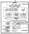
以下、本発明の実施例について図面を用いて詳細に説明する。図1は、本発明の携帯通信端末の実施例の構成を示すブロック図である。実施例の携帯通信端末である携帯電話機101は、図1に示すように、複数の音響入力手段及び複数の音響出力手段を有する音響入出力部10と、音声のみの一般的な通話、テレビ電話による通話、動画像の録画・再生及び音声・音楽の再生等の通信処理を選択的に実行する通信処理部20と、通信処理部20での通信処理に応じて音響入出力部10に動作指示を与える音響処理部50とを備える。
[Example 1]
Hereinafter, embodiments of the present invention will be described in detail with reference to the drawings. FIG. 1 is a block diagram showing a configuration of an embodiment of a mobile communication terminal of the present invention. As shown in FIG. 1, a
音響入出力部10は、音響出力手段となるスピーカであるSPK11及びSPK駆動部12と、同じく音響出力手段であって受話機能を果たすレシーバであるREC13及びREC駆動部14と、それぞれが音声入力手段となるマイクロホンであるMIC15a及びMIC15bと、これらのMIC15a及び15bに対し後述の入出力切り換えを行うための入出力スイッチ16a及び入出力スイッチ16bと、各MIC15a及び15bにより入力される音響を検出するMIC入力検出部17とを有する。
The sound input / output unit 10 includes SPK11 and SPK drive unit 12 which are speakers serving as sound output means, and REC 13 and REC drive unit 14 which are also sound output means and perform a reception function, and each of which is a sound input means.
通信処理部20は、携帯電話機101の無線信号を送受信するための送受信ANT(アンテナ)21と、無線信号の変復調を行う携帯電話用無線部22と、携帯電話の信号処理を行うシステム処理部23と、CPU24と、操作入力部であるキー25と、キー25の入力を検出するキー検出部26と、表示機能を果たすLCD27及びLCD駆動部28と、プログラムを格納するROM29と、データを格納するRAM30とを有する。
The communication processing unit 20 includes a transmission / reception ANT (antenna) 21 for transmitting / receiving a radio signal of the
本実施例のMIC15a及びMIC15bは、音響入力手段としての機能を果たす他に、SPK11のような音響出力手段としての機能も果たす。具体的には、携帯電話機101による通話や録画のような通信処理に応じて、各MIC15a及び15bをマイクロホン又はスピーカとして稼動させる。この制御は、音響処理部50が、SPK駆動部12及びMIC入力検出部17に動作指示を与え、これにより入出力スイッチ16a及び16bが音響信号の接続切り換えを行うことにより実現される。このように、本来は音響入力手段となる各MIC15a及び15bを、音響出力手段としても機能させることにより、スピーカデバイスの追加配置が不要となり、携帯電話機101における設計スペースの有効利用を図ることができる。
The
上述した各MIC15a及び15bのように、音響の入力および出力機能を果たし得るデバイスとしては、例えば、マイクロホンの一種であるダイナミックマイクロホンを用いることができる。ダイナミックマイクロホンは、従来知られているように、磁石の磁場の中に、音響板に接続されたコイルが配置されており、音響板の振動がコイルに伝達して磁場が変動することにより、コイルに入力信号の電流が流れるという仕組みを持つ。
As each of the
一方、従来のスピーカには、上記ダイナミックマイクロホンと同様な構成を持つものが存在し、このスピーカの場合、コイルに電流を流すことによる磁場の発生により、コイルに接続された音響板が振動して音が外部出力される。よって、ダイナミックマイクロホンに対する動作指示を制御することにより、このマイクロホンが音響の選択的な入出力を実現する。なお、このような手法は、例えば、無線機のスピーカマイクなどに適用されることが一般的に知られており、本実施例では、この手法を携帯電話機101のMIC15a及びMIC15bに利用する。
On the other hand, some conventional speakers have the same configuration as that of the dynamic microphone. In this speaker, the acoustic plate connected to the coil vibrates due to the generation of a magnetic field caused by passing a current through the coil. Sound is output externally. Therefore, by controlling the operation instruction to the dynamic microphone, this microphone realizes selective input / output of sound. In addition, it is generally known that such a method is applied to, for example, a speaker microphone of a wireless device. In this embodiment, this method is used for the
図2に、実施例の携帯電話機101の外観を概略的に示す。図2の(a)に示すように、携帯電話機101は、REC13及びLCD27を有する筐体上部101aと、キー25を有する筐体下部101bとがヒンジ機構101cにより接続された折りたたみ型の電話機であり、筐体下部101bには、上記説明したMIC15a及びMIC15bが設けられている。また、同図の(b)に示すように、筐体上部101aの表面、すなわちLCD27の面と背向する面には、SPK11が設けられている。
FIG. 2 schematically shows the appearance of the
実施例の携帯電話機101の動作手順を図3のフローチャートに沿って説明する。携帯電話機101が起動すると(ステップS1)、音響処理部50は、音響入出力部10に対する初期化処理として、SPK駆動部12、MIC入力検出部17、入出力スイッチ16a及び16bに、各MIC15a及び15bをマイク動作モード、SPK11をモノラルスピーカ(Left+Right)動作モードを設定する(ステップS2)。また、図3には示さないが、このときREC13がレシーバ動作モードに設定されている。
The operation procedure of the
マイク動作モードでは、各MIC15a及び15bが稼動するとき、これらに、音響の外部入力を行うための動作パラメータが設定される。レシーバ動作モードでの稼動時は、ユーザがREC13を耳に接触させる受話操作に適した音量で音声出力するための動作パラメータが設定される。スピーカ動作モードでの稼動時は、テレビ電話時のようにユーザが携帯電話機101と対向して利用するのに適した音量で音声出力するためのパラメータが設定される。このスピーカ動作モードでは、上記のレシーバ動作モードに比べ、より大きく明瞭な音声出力を求められることから、より大きな出力ゲインを設定すると共に、周波数特性の低周波数帯域を高く設定する。
In the microphone operation mode, when each of the
上記の初期化処理が完了すると、通信処理部20のCPU24は、携帯電話機101の動作状態を監視し、状態に応じて、音響処理部50に対し音響入出力部10の動作モードを指定する(ステップS3)。
When the initialization process is completed, the
例えば、ユーザが携帯電話機101にて一般的な通話、すなわち音声のみによる通話を開始するとき(ステップS3a)、CPU24は、MIC15a及びMIC15bのいずれか一方をマイク動作モードにて稼動させると共に、他方のマイクおよびSPK11をOFFモード、すなわち稼動を停止するよう音響処理部50に指定する(ステップS4)。一般的な通話時は、各MIC15a及び15bがユーザの口元に接近しており、発声を捕捉し易いことから、いずれか一方のマイクロホンを稼動させ、他方を停止させる。これにより、電力の消耗を抑制することができる。
For example, when the user starts a general call using the
また、テレビ電話による通話開始時には(ステップS3b)、MIC15aをステレオ(Left)マイク動作モードにて稼動させると共に、MIC15bをステレオ(Right)マイク動作モードにて稼動させ、SPK11をスピーカ動作モードにて稼動させる(ステップS5)。このとき、各MIC15a及び15bに対しては、ステレオ音響入力のための動作パラメータが設定される。これにより、携帯電話機101は、両MIC15a及び15bより多くの音声の捕捉が可能となると共に、臨場感のある音声データを取得することができる。
At the start of a videophone call (step S3b), the MIC 15a is operated in a stereo left microphone operation mode, the MIC 15b is operated in a stereo right microphone operation mode, and the SPK 11 is operated in a speaker operation mode. (Step S5). At this time, operation parameters for stereo sound input are set for each of the
動画像の録画開始時は(ステップS3c)、MIC15aをステレオ(Left)マイク動作モード、MIC15bをステレオ(Right)マイク動作モードに設定することにより、上述と同様なステレオ音響入力を行い、また、録画時においては音響の外部出力は不要であることから、SPK11をOFFモードに設定する(ステップS6)。
When recording a moving image (step S3c), the
また、動画像の再生時、あるいは既に録音された音声や配信された音楽の再生時は(ステップS3d、S3e)、MIC15aをステレオ(Left)スピーカ動作モード、MIC15bをステレオ(Right)スピーカ動作モード、そしてSPK11をモノラル(Left+Right)スピーカ動作モードに設定する(ステップS7)。この設定により、各MIC15a及び15bは、本来の音響入力手段として動作することに代えて、SPK11と共に音響を外部出力する手段として動作する。
When playing back a moving image, or when playing back already recorded audio or distributed music (steps S3d and S3e), the
各MIC15a及び15bの動作の切り換えは、上記説明したように、入出力スイッチ16a及び16bにより、各MIC15a及び15bの接続をMIC入力検出部17からSPK駆動部12に切り換えることにより実行される。上記設定により、SPK11からの音響出力に加え、両MIC15a及び15bによるステレオ音響出力が実行されることから、臨場感のある音声や音楽をユーザに提供することができる。このようにして、各MIC15a及び15bを活用することにより、いわゆるマルチスピーカシステムを構築することができる。
As described above, the operation of each
CPU24は、上述の何れかの通信処理が終了する毎に(ステップS8:Yes)、再び状態を監視すべくステップS3に戻る。
The
[実施例2]
上記説明した実施例1では、一般的な通話時に(ステップS3a)、各MIC15a及び15bのいずれか一方をOFFモードに設定したが(ステップS4)、OFFモードに設定すべきマイクロホンを所定条件に基づき決定するようにしてもよい。その手順を図4のフローチャートに沿って説明する。なお、図4において、実施例1に係る図3の符号と同一の符号を付された手順は、実施例1のそれと同様であり、ここでは説明を省略する。
[Example 2]
In the first embodiment described above, either one of the
図4に示すように、携帯電話機101は、起動時(ステップS21)の初期化処理として、MIC15a及びMIC15bをOFFモードとする(ステップS22)。そして、通話開始時(ステップS3a)、まず双方のMIC15a及び15bをマイク動作モードに設定する(ステップS23)。
As shown in FIG. 4, the
次いで、ユーザが通話を開始したとき(ステップS3a)、音響処理部50が、MIC入力検出部17により検出された各MIC15a及び15bの入力レベルを比較し、その結果、MIC15aの入力レベルが他方のMIC15bのそれよりも大きい場合(ステップS24:Yes)、MIC15bの稼動を停止させるべく、これをOFFモードに設定し、MIC15aのほうをマイク動作モードにて稼動させる(ステップS25)。また、MIC15aの入力レベルのほうが小さい場合は(ステップS24:No)、このMIC15aにOFFモードを設定し、MIC15bのほうをマイク動作モードにて稼動させる(ステップS26)。なお、図示のように、テレビ電話時(ステップS3b)においても、上記の手順と同様にして、一方のマイクロホンを停止させるようにすることができる(ステップS27〜30)。
Next, when the user starts a call (step S3a), the
実施例2の手順によれば、携帯電話機101の消費電力を抑制できると共に、より良好な音声入力を実現するマイクロホンを自動的に選択することができる。
According to the procedure of the second embodiment, the power consumption of the
[実施例3]
図5は、実施例3の携帯電話機103の構成を示すブロック図である。携帯電話機103は、図1に沿って説明した携帯電話機101と同様な折りたたみ型の端末であり、携帯電話機101の構成に加え、音響入力手段としてのマイクロホンであるMIC15cと、筐体の開閉状態を検出する開閉検出部31とを備える。開閉検出部31としては、例えば、一般的な折りたたみ型の携帯電話機において、折りたたみ内側のヒンジ機構付近に設けられる圧力センサを用いることができる。
[Example 3]
FIG. 5 is a block diagram illustrating a configuration of the
図6に、携帯電話機103の外観を概略的に示す。携帯電話機103は、同図(a)に示すように、筐体上部103aの表面にMIC15a及びMIC15bとSPK11とが設けられ、また、筐体下部103bにおけるキー25の面にMIC15cが設けられている。同図(b)に、携帯電話機103の筐体が閉じられた状態、すなわち筐体下部103bのキー25の面に対し筐体上部103aを重ね合わせた状態を示す。
FIG. 6 schematically shows the appearance of the
携帯電話機103の動作手順を図7のフローチャートに沿って説明する。なお、図7において、実施例1に係る図3の符号と同一の符号を付された手順は、実施例1のそれと同様であり、ここでは説明を省略する。携帯電話機103は、起動時(ステップS31)の初期化処理において、MIC15a及びMIC15bをOFFモードとすると共に、MIC15cをMIC動作モードに設定する(ステップS32)。
The operation procedure of the
次いで、通話開始時(ステップS3a)、CPU24は、開閉検出部31により携帯電話機103筐体の開閉状態を確認し、その結果、筐体が開いた状態、すなわち図6(a)に示すような状態にある場合(ステップS33:No)、その旨を音響処理部50に通知する。音響処理部50は、図6(a)の状態での通話に不要となる各MIC15a及び15bと、SPK11とをOFFモードに設定すると共に、図示の状態において通話時の送話手段となるMIC15cをMIC動作モードにて稼動させる(ステップS34)。
Next, at the start of a call (step S3a), the
通話時に、筐体が折りたたみ状態、すなわち図6(b)に示す状態にある場合(ステップS33:Yes)、音響処理部50は、図示の状態での通話を可能とすべく、筐体上部103aの表面にあるMIC15a及びMIC15bを送話手段としてMIC動作モードにて稼動させ、SPK11を受話手段としてレシーバ動作モードにて稼動させる。そして、図示の状態では利用不可となるMIC15cをOFFモードに設定する(ステップS35)。
If the case is in a folded state, that is, in the state shown in FIG. 6B during a call (step S33: Yes), the
また、テレビ電話開始時は(ステップS3b)、図6(b)のような折りたたみ状態にある場合(ステップS36:Yes)、各MIC15a及び15bをMIC動作モードにて稼動させ、SPK11をモノラル(Left+Right)スピーカ動作モードにて稼動させ、MIC15cをOFFモードに設定する。テレビ電話時に携帯電話機103の筐体が開いている状態であれば(ステップS36:No)、各MIC15a及び15bをOFFモードに設定し、MIC15cをMIC動作モードにて稼動させると共に、SPK11をモノラル(Left+Right)スピーカ動作モードにて稼動させる。
At the start of the videophone (step S3b), when in the folded state as shown in FIG. 6B (step S36: Yes), the
よって、携帯電話機103によれば、筐体の開閉状態に応じて、一般的な通話またはテレビ電話による通話に適した音響の入出力機能を提供することができる。
Therefore, according to the
また、動画像の録画時(ステップS3c)、動画像の再生時(ステップS3d)及び音声・音楽再生時(ステップS3e)は、それぞれにおいてMIC15cをOFFモードに設定し、図3に示す実施例1のステップS6及びS7と同様な設定を行う(ステップS39、S40)。
Further, at the time of recording a moving image (step S3c), at the time of reproducing a moving image (step S3d), and at the time of sound / music reproduction (step S3e), the
[実施例4]
図8は、実施例4の携帯電話機104の構成を示すブロック図である。携帯電話機104の音響入出力部10は、音響出力手段として、SPK11と、REC13a及びREC13bとを備え、また、各REC13a及び13bに対し、上記説明したレシーバ動作モードまたはスピーカ動作モードを切り換え設定するための信号源スイッチ18a及び信号源スイッチ18bを備える。
[Example 4]
FIG. 8 is a block diagram illustrating a configuration of the
信号源スイッチ18aは、例えばREC13aが、レシーバ動作モードにて稼動するとき、このREC13aをREC駆動部14に接続し、また、後述の所定の通信処理においてスピーカ動作モードに設定されるとき、このREC13aをSPK駆動部12に接続する。
For example, when the
図9に、携帯電話機104の外観を概略的に示す。携帯電話機104は、筐体上部104aと筐体下部104bとが回転軸機構104cにより接続されたロータリー型の携帯電話機であり、図9に示すように、筐体上部104aのLCD27近傍にREC13a及びREC13bが設けられ、筐体下部104bのキー25近傍にMIC15が設けられている。また、筐体下部104bの先端面にSPK11が設けられている。
FIG. 9 schematically shows the appearance of the
携帯電話機104の動作手順を図10のフローチャートに沿って説明する。携帯電話機104は、起動時(ステップS41)の初期化処理として、REC13a及びREC13bをレシーバ動作モードに設定し、SPK11をモノラル(Left+Right)スピーカ動作モードに設定する(ステップS42)。
The operation procedure of the
携帯電話機104における一般的な通話時は(ステップS3a)、ユーザが携帯電話機104を耳に接触させて利用することから、REC13a及びREC13bの何れか一方をレシーバ動作モードにて稼動させ、他方のレシーバ及びSPK11をOFFにする(ステップS43)。図示の例では、REC13aを稼動させ、他方のREC13bをOFFにしている。
During a general call on the mobile phone 104 (step S3a), since the user uses the
また、テレビ電話による通話時は(ステップS3b)、REC13aをステレオ(Left)スピーカ動作モードにて稼動させ、REC13bをステレオ(Right)スピーカ動作モードにて稼動させ、SPK11をモノラル(Left+Right)スピーカ動作モードにて稼動させる(ステップS44)。これにより、テレビ電話時において、3つの音響出力手段を用いた臨場感のある音声を提供することができる。
During a videophone call (step S3b), the
動画像の録画時は(ステップS3c)、音響の外部出力が不要となることから、音響出力手段であるREC13a、REC13b、及びSPK11のすべてをOFFモードに設定する(ステップS45)。また、動画像の再生時(ステップS3d)及び音声・音楽の再生時(ステップS3e)は、テレビ電話時の上記ステップS44と同様に、REC13a及び13bによるステレオ音響出力と、SPK11によるモノラル出力を行う(ステップS46)。
When recording a moving image (step S3c), since no external sound output is required, all of the sound output means REC13a, REC13b, and SPK11 are set to the OFF mode (step S45). Also, during the playback of moving images (step S3d) and the playback of voice / music (step S3e), the stereo sound output by the
なお、実施例4の上記説明では、携帯電話機104として図9に示すようなロータリー型の端末を用いたが、図8の構成を成すものであれば、折りたたみ型の端末に上記手順を適用することができる。
In the above description of the fourth embodiment, a rotary type terminal as shown in FIG. 9 is used as the
[実施例5]
本発明においては、上記携帯電話機104のようなロータリー型の端末における通話時及びテレビ電話時の音響出力を、筐体の開閉状態に応じて制御することができる。その手法を実施例5として以下に説明する。
[Example 5]
In the present invention, sound output at the time of a telephone call and a videophone call on a rotary terminal such as the
実施例5の携帯電話機105の外観を図11に概略的に示す。ロータリー型の端末である携帯電話機105は、図11(a)に示すように、筐体上部105aの先端付近にREC13aが設けられ、このREC13aからLCD27を挟んで回転軸機構105c近傍にREC13bが設けられている。なお、他の音響出力手段であるSPK11の配置は、図9に示す携帯電話機104と同様である。
The appearance of the
また、携帯電話機105が閉じられた状態、すなわち回転軸機構105cにより筐体上部105aを旋回させ、これを筐体下部105bに重ね合わせた状態を同図(b)に示す。この図から分かるように、携帯電話機105は、筐体が閉じられた状態にあっても、筐体下部105bのMIC15が露出するように形成されている。これにより、図11(a)のような携帯電話機105が開いた状態、あるいは同図(b)のように閉じた状態のいずれであっても、MIC15を音響入力手段として共用することができる。
Further, FIG. 5B shows a state in which the
携帯電話機105は、筐体の開閉状態を図8に示す開閉検出部31により検出する。この開閉検出部31としては、例えば、実施例3にて説明した圧力センサを用い、これを筐体上部105aの表面の先端付近、すなわち、LCD27の面と背向する面の先端付近に設けることにより、図11(b)の状態を筐体の閉じた状態として検出することができる。
The
携帯電話機105の動作手順を図12のフローチャートに沿って説明する。なお、動画像の録画時(ステップS3c)、動画像の再生時(ステップS3d)及び音声・音楽の再生時(ステップS3e)における手順は、図10に沿って説明した実施例4のものと同様であり、ここでは説明を省略する。
The operation procedure of the
携帯電話機105は、起動時(ステップS51)の初期化処理において、REC13a及びREC13bをOFFにし、SPK11をモノラル(Left+Right)スピーカ動作モードに設定する(ステップS52)。
In the initialization process at the time of activation (step S51), the
一般的な通話時(ステップS3a)、CPU24は、開閉検出部31により筐体の開閉状態を確認し、その結果を音響処理部50へ通知する。具体的には、例えば図11(b)のような回転収納状態、すなわち筐体が閉じた状態にある場合(ステップS53:Yes)、回転軸機構104c近傍のREC13bを送話手段として利用すべく、これをレシーバ動作モードにて稼動させ、他方のREC13a及びSPK11をOFFにする(ステップS54)。
During a general call (step S <b> 3 a), the
また、図11(a)のように筐体が開いた状態にある場合は(ステップS53:No)、REC13aを送話手段として利用するために、これをレシーバ動作モードにて稼動させ、他方のREC13bとSPK11とをOFFにする(ステップS55)。
Further, when the housing is in the open state as shown in FIG. 11A (step S53: No), in order to use the
テレビ電話にて通話の際は(ステップS3b)、筐体が開いた状態(ステップS56:Yes)または閉じた状態(ステップS56:No)において、REC13aをステレオ(Left)スピーカ動作モードにて稼動させ、REC13bをステレオ(Right)スピーカ動作モードにて稼動させ、SPK11をモノラル(Left+Right)スピーカ動作モードにて稼動させる。なお、筐体の開閉状態に応じて、REC13aおよびREC13bのステレオ出力の(Left)および(Right)を反転させてもよい。
During a videophone call (step S3b), the
101〜105 携帯電話機
10 音響入出力部
11:SPK、12:SPK駆動部、13:REC、14:REC駆動部、15:MIC、16:入出力スイッチ、17:MIC入力検出部、18:信号源スイッチ
20 通信処理部
21:送受信アンテナ、22:携帯電話用無線部、23:システム処理部、24:CPU、25:キー、26:キー検出部、27:LCD、28:LCD駆動部、29:ROM、30:RAM、31:開閉検出部
50 音響処理部
101-105 cellular phone 10 sound input / output unit 11: SPK, 12: SPK drive unit, 13: REC, 14: REC drive unit, 15: MIC, 16: input / output switch, 17: MIC input detection unit, 18: signal Source switch 20 Communication processing unit 21: Transmission / reception antenna, 22: Mobile phone radio unit, 23: System processing unit, 24: CPU, 25: Key, 26: Key detection unit, 27: LCD, 28: LCD drive unit, 29 : ROM, 30: RAM, 31: Opening /
Claims (7)
前記音響入出力部は複数のマイクロホンを有し、
前記音響処理部は、出力すべき音響の音量に関する動作パラメータ値を通信処理に応じて変化させ、且つ、前記複数のマイクロホンから入力される音響の音量を比較し、最も小さい音量となるマイクロホンに対し稼動停止の動作パラメータ値を設定することを特徴とする携帯通信端末。 A sound input / output unit that performs sound input / output; a communication processing unit that performs communication processing related to input / output sound; and an acoustic processing unit that sets operation parameter values that define the sound input / output operation;
The acoustic input / output unit has a plurality of microphones,
The sound processing unit changes an operation parameter value related to a sound volume to be output according to communication processing, compares sound volumes input from the plurality of microphones, and determines a minimum sound volume for the microphone. A mobile communication terminal characterized in that an operation parameter value for operation stop is set .
前記通信処理部は、筐体の閉じた状態において通信処理を実行することを特徴とする請求項5記載の携帯通信端末。 The acoustic input / output unit includes a speaker and the plurality of microphones on a surface exposed when the casing is closed by a hinge mechanism,
The portable communication terminal according to claim 5 , wherein the communication processing unit executes communication processing in a state where the housing is closed.
Priority Applications (4)
| Application Number | Priority Date | Filing Date | Title |
|---|---|---|---|
| JP2004039977A JP3904086B2 (en) | 2004-02-17 | 2004-02-17 | Mobile communication terminal |
| EP05090031A EP1564971A1 (en) | 2004-02-17 | 2005-02-16 | Portable communication terminal |
| US11/058,273 US7433704B2 (en) | 2004-02-17 | 2005-02-16 | Portable communication terminal |
| CN2005100640850A CN1658621A (en) | 2004-02-17 | 2005-02-16 | Portable communication terminal |
Applications Claiming Priority (1)
| Application Number | Priority Date | Filing Date | Title |
|---|---|---|---|
| JP2004039977A JP3904086B2 (en) | 2004-02-17 | 2004-02-17 | Mobile communication terminal |
Publications (2)
| Publication Number | Publication Date |
|---|---|
| JP2005236385A JP2005236385A (en) | 2005-09-02 |
| JP3904086B2 true JP3904086B2 (en) | 2007-04-11 |
Family
ID=34697986
Family Applications (1)
| Application Number | Title | Priority Date | Filing Date |
|---|---|---|---|
| JP2004039977A Expired - Fee Related JP3904086B2 (en) | 2004-02-17 | 2004-02-17 | Mobile communication terminal |
Country Status (4)
| Country | Link |
|---|---|
| US (1) | US7433704B2 (en) |
| EP (1) | EP1564971A1 (en) |
| JP (1) | JP3904086B2 (en) |
| CN (1) | CN1658621A (en) |
Families Citing this family (9)
| Publication number | Priority date | Publication date | Assignee | Title |
|---|---|---|---|---|
| JP5117032B2 (en) * | 2005-11-07 | 2013-01-09 | エルジー電子株式會社 | Mobile terminal and mode switching method thereof |
| KR101218677B1 (en) * | 2005-11-07 | 2013-01-18 | 엘지전자 주식회사 | Mobile terminal and its mode switching method |
| KR100810354B1 (en) * | 2006-01-10 | 2008-03-04 | 삼성전자주식회사 | Mobile phone with game |
| DE102006033000B4 (en) * | 2006-07-17 | 2012-05-31 | Hewlett-Packard Development Co., L.P. | Mobile phone with sensor-controlled speaker and microphone activation |
| JP4379505B2 (en) * | 2007-08-23 | 2009-12-09 | 株式会社カシオ日立モバイルコミュニケーションズ | Mobile terminal device |
| JP5247384B2 (en) * | 2008-11-28 | 2013-07-24 | キヤノン株式会社 | Imaging apparatus, information processing method, program, and storage medium |
| CN103517187B (en) * | 2012-06-29 | 2015-09-23 | 联想(北京)有限公司 | A kind of method and electronic equipment controlling voice output |
| US10356229B2 (en) * | 2015-12-31 | 2019-07-16 | Shenzhen Royole Technologies Co., Ltd. | Flexible wearable device |
| US10356517B2 (en) * | 2016-08-08 | 2019-07-16 | Marshall Electronics, Inc. | Blended passive microphone |
Family Cites Families (47)
| Publication number | Priority date | Publication date | Assignee | Title |
|---|---|---|---|---|
| JPS57210752A (en) | 1981-06-22 | 1982-12-24 | Nippon Telegr & Teleph Corp <Ntt> | Telephone set |
| US4792986A (en) * | 1985-12-11 | 1988-12-20 | General Electric Company | Portable radio system with externally programmable universal device connector |
| JPH01268242A (en) | 1988-04-19 | 1989-10-25 | Nec Corp | Radio telephony set |
| JPH0591583A (en) | 1991-09-30 | 1993-04-09 | Toshiba Corp | Earphone |
| US5224151A (en) * | 1992-04-01 | 1993-06-29 | At&T Bell Laboratories | Automatic handset-speakephone switching arrangement for portable communication device |
| US5673325A (en) * | 1992-10-29 | 1997-09-30 | Andrea Electronics Corporation | Noise cancellation apparatus |
| FI111896B (en) | 1995-11-24 | 2003-09-30 | Nokia Corp | Function to facilitate double-acting communication device operation, and double-acting communication device |
| DE19638114A1 (en) * | 1996-09-18 | 1998-04-02 | Siemens Ag | Method for setting terminal-specific parameters of a communication terminal |
| JP3209150B2 (en) | 1997-08-12 | 2001-09-17 | 日本電気株式会社 | Foldable portable wireless communication device |
| JPH1168685A (en) * | 1997-08-21 | 1999-03-09 | Sony Corp | Method and equipment for radio information communication |
| JP3130851B2 (en) * | 1997-12-09 | 2001-01-31 | 埼玉日本電気株式会社 | Foldable mobile phone |
| JP2908421B1 (en) | 1998-04-02 | 1999-06-21 | 静岡日本電気株式会社 | Mobile phone equipment |
| JP3042681B2 (en) * | 1998-04-15 | 2000-05-15 | 怡利電子工業股▲ひん▼有限公司 | A handset that does not need to be gripped by a mobile phone combined with the speaker of a car audio system |
| GB2372666B (en) | 1998-05-08 | 2002-11-27 | Orange Personal Comm Serv Ltd | Mobile communications |
| JP2000184086A (en) * | 1998-12-21 | 2000-06-30 | Sharp Corp | Information communication terminal equipment and recording medium for control program therefor |
| US6349225B1 (en) * | 1999-04-01 | 2002-02-19 | Ericsson Inc. | Hearing protection for a wireless communications device |
| US6360203B1 (en) * | 1999-05-24 | 2002-03-19 | Db Systems, Inc. | System and method for dynamic voice-discriminating noise filtering in aircraft |
| US7260231B1 (en) * | 1999-05-26 | 2007-08-21 | Donald Scott Wedge | Multi-channel audio panel |
| FR2794588B1 (en) * | 1999-06-03 | 2002-11-15 | Jacques Lewiner | COMBINED LOCAL TELEPHONY AND ALARM SYSTEM |
| US6751446B1 (en) * | 1999-06-30 | 2004-06-15 | Lg Electronics Inc. | Mobile telephony station with speaker phone function |
| US7031474B1 (en) * | 1999-10-04 | 2006-04-18 | Srs Labs, Inc. | Acoustic correction apparatus |
| GB2355128B (en) * | 1999-10-08 | 2003-04-09 | Nokia Mobile Phones Ltd | Portable electronics device |
| US6549630B1 (en) * | 2000-02-04 | 2003-04-15 | Plantronics, Inc. | Signal expander with discrimination between close and distant acoustic source |
| GB2359177A (en) | 2000-02-08 | 2001-08-15 | Nokia Corp | Orientation sensitive display and selection mechanism |
| US6774578B2 (en) * | 2000-09-19 | 2004-08-10 | Semiconductor Energy Laboratory Co., Ltd. | Self light emitting device and method of driving thereof |
| JP4716238B2 (en) | 2000-09-27 | 2011-07-06 | 日本電気株式会社 | Sound reproduction system and method for portable terminal device |
| JP3542955B2 (en) | 2000-10-11 | 2004-07-14 | 埼玉日本電気株式会社 | Mobile phone |
| JP3929704B2 (en) | 2001-01-12 | 2007-06-13 | 富士フイルム株式会社 | Imaging device with communication function |
| JP2002281135A (en) * | 2001-03-21 | 2002-09-27 | Nec Viewtechnology Ltd | Portable telephone |
| US7492909B2 (en) * | 2001-04-05 | 2009-02-17 | Motorola, Inc. | Method for acoustic transducer calibration |
| US20030114206A1 (en) * | 2001-08-24 | 2003-06-19 | United Parcel Service Of America, Inc. | Portable data acquisition and management system and associated device and method |
| EP1316814A1 (en) * | 2001-11-30 | 2003-06-04 | Cross Point RFAPP B.V. i.o. | Tracing of transponder-tagged objects |
| JP4298948B2 (en) | 2001-12-27 | 2009-07-22 | 日東精工株式会社 | Internal thread forming scrap adsorbing tapping screw |
| KR100605885B1 (en) * | 2001-12-29 | 2006-08-01 | 삼성전자주식회사 | Sound signal output device and method of mobile communication terminal |
| KR100453042B1 (en) | 2002-02-18 | 2004-10-15 | 삼성전자주식회사 | A portable telephone, control method, and recording medium therefor |
| ATE459191T1 (en) * | 2002-04-09 | 2010-03-15 | Palm Inc | MOBILE COMMUNICATION TERMINAL WITH HANDSFREE OPERATION |
| AU2003227210A1 (en) * | 2002-04-30 | 2003-11-17 | Ntt Data Corporation | Mobile terminal server |
| AU2003244104A1 (en) * | 2002-06-07 | 2003-12-22 | Matsushita Electric Industrial Co., Ltd. | Collapsible mobile telephone |
| JP3921138B2 (en) | 2002-06-26 | 2007-05-30 | 京セラ株式会社 | Portable information terminal device |
| KR100696439B1 (en) * | 2002-07-02 | 2007-03-19 | 노키아 코포레이션 | Method and mobile communication device for handling data records by speech recognition |
| ATE322791T1 (en) | 2002-07-17 | 2006-04-15 | Sony Ericsson Mobile Comm Ab | MOBILE TELECOMMUNICATION TERMINAL WITH ACOUSTIC SHOCK PROTECTION |
| JP4080395B2 (en) * | 2002-08-02 | 2008-04-23 | シャープ株式会社 | Portable information processing device |
| US6819946B2 (en) * | 2002-10-04 | 2004-11-16 | Sony Ericsson Mobile Communications Ab | Apparatus and method for controlling source of sound emitted from a mobile terminal |
| US7200411B2 (en) * | 2003-01-30 | 2007-04-03 | Matsushita Electric Industrial Co., Ltd. | Portable information terminal and communication system |
| US7249025B2 (en) * | 2003-05-09 | 2007-07-24 | Matsushita Electric Industrial Co., Ltd. | Portable device for enhanced security and accessibility |
| US20050026568A1 (en) * | 2003-08-01 | 2005-02-03 | Hawker Larry E. | System and method of acoustically safe automatic handsfree volume adjustment |
| JP4139786B2 (en) * | 2004-02-17 | 2008-08-27 | シャープ株式会社 | Display device and driving method thereof |
-
2004
- 2004-02-17 JP JP2004039977A patent/JP3904086B2/en not_active Expired - Fee Related
-
2005
- 2005-02-16 CN CN2005100640850A patent/CN1658621A/en active Pending
- 2005-02-16 EP EP05090031A patent/EP1564971A1/en not_active Withdrawn
- 2005-02-16 US US11/058,273 patent/US7433704B2/en not_active Expired - Fee Related
Also Published As
| Publication number | Publication date |
|---|---|
| US20050181820A1 (en) | 2005-08-18 |
| EP1564971A1 (en) | 2005-08-17 |
| JP2005236385A (en) | 2005-09-02 |
| CN1658621A (en) | 2005-08-24 |
| US7433704B2 (en) | 2008-10-07 |
Similar Documents
| Publication | Publication Date | Title |
|---|---|---|
| JP4733121B2 (en) | Method and apparatus for improved mobile station and hearing aid compatibility | |
| KR100818460B1 (en) | Sound outputting apparatus and sound outputting method | |
| JP3542955B2 (en) | Mobile phone | |
| JP2010054731A (en) | Noise suppressing device, mobile phone, noise suppressing method and computer program | |
| JP2003018078A (en) | Radio mobile terminal unit, received call loudspeaking method, and program thereof | |
| JP5533658B2 (en) | Mobile terminal, mobile terminal control method and program | |
| JP3904086B2 (en) | Mobile communication terminal | |
| JP4340885B2 (en) | Foldable mobile phone | |
| WO2001099469A1 (en) | Speech reproduction system, speech signal generator system and calling system | |
| JP2001268187A (en) | Call tone ringing system and method for flip type mobile phone | |
| JP2006042077A (en) | Portable communication terminal and ringtone volume control method for portable communication terminal | |
| JP2003023479A (en) | Portable radio terminal | |
| JP4269020B2 (en) | Mobile communication terminal | |
| WO2009145312A1 (en) | Mobile communication device and communication control method | |
| JP2002223279A (en) | Communication terminal device | |
| JP2004173137A (en) | Folding mobile phone | |
| JP4698349B2 (en) | Portable information terminal and audio output control program | |
| JP4030385B2 (en) | Electronics | |
| US20070165884A1 (en) | Information processing apparatus and sound control method therefor | |
| JP2007267014A (en) | Cellular phone, howling prevention control method, program, and recording medium | |
| KR100965727B1 (en) | Mobile communication terminal having a plurality of microphones | |
| JP2005341329A (en) | Portable telephone terminal and portable telephone system | |
| JP2007006387A (en) | Portable terminal apparatus | |
| KR100787973B1 (en) | Speaker Drive On / Off Control Method in Mobile Communication Terminal | |
| KR20030076041A (en) | Remote controller for portable audio device with a function of hands-free |
Legal Events
| Date | Code | Title | Description |
|---|---|---|---|
| A977 | Report on retrieval |
Free format text: JAPANESE INTERMEDIATE CODE: A971007 Effective date: 20060201 |
|
| A131 | Notification of reasons for refusal |
Free format text: JAPANESE INTERMEDIATE CODE: A131 Effective date: 20060210 |
|
| A521 | Request for written amendment filed |
Free format text: JAPANESE INTERMEDIATE CODE: A523 Effective date: 20060404 |
|
| A131 | Notification of reasons for refusal |
Free format text: JAPANESE INTERMEDIATE CODE: A131 Effective date: 20060926 |
|
| A521 | Request for written amendment filed |
Free format text: JAPANESE INTERMEDIATE CODE: A523 Effective date: 20061124 |
|
| TRDD | Decision of grant or rejection written | ||
| A01 | Written decision to grant a patent or to grant a registration (utility model) |
Free format text: JAPANESE INTERMEDIATE CODE: A01 Effective date: 20061220 |
|
| A61 | First payment of annual fees (during grant procedure) |
Free format text: JAPANESE INTERMEDIATE CODE: A61 Effective date: 20070102 |
|
| R150 | Certificate of patent or registration of utility model |
Free format text: JAPANESE INTERMEDIATE CODE: R150 |
|
| FPAY | Renewal fee payment (event date is renewal date of database) |
Free format text: PAYMENT UNTIL: 20110119 Year of fee payment: 4 |
|
| FPAY | Renewal fee payment (event date is renewal date of database) |
Free format text: PAYMENT UNTIL: 20110119 Year of fee payment: 4 |
|
| FPAY | Renewal fee payment (event date is renewal date of database) |
Free format text: PAYMENT UNTIL: 20120119 Year of fee payment: 5 |
|
| FPAY | Renewal fee payment (event date is renewal date of database) |
Free format text: PAYMENT UNTIL: 20130119 Year of fee payment: 6 |
|
| R250 | Receipt of annual fees |
Free format text: JAPANESE INTERMEDIATE CODE: R250 |
|
| LAPS | Cancellation because of no payment of annual fees |