JP3897197B2 - Blow-by gas reduction structure for outboard engine - Google Patents
Blow-by gas reduction structure for outboard engine Download PDFInfo
- Publication number
- JP3897197B2 JP3897197B2 JP26811597A JP26811597A JP3897197B2 JP 3897197 B2 JP3897197 B2 JP 3897197B2 JP 26811597 A JP26811597 A JP 26811597A JP 26811597 A JP26811597 A JP 26811597A JP 3897197 B2 JP3897197 B2 JP 3897197B2
- Authority
- JP
- Japan
- Prior art keywords
- blow
- intake
- engine
- cylinder
- surge tank
- Prior art date
- Legal status (The legal status is an assumption and is not a legal conclusion. Google has not performed a legal analysis and makes no representation as to the accuracy of the status listed.)
- Expired - Lifetime
Links
- 238000002485 combustion reaction Methods 0.000 description 3
- 238000005192 partition Methods 0.000 description 3
- 239000000446 fuel Substances 0.000 description 2
- 230000005484 gravity Effects 0.000 description 2
- 238000011144 upstream manufacturing Methods 0.000 description 2
- 230000005540 biological transmission Effects 0.000 description 1
- 230000000694 effects Effects 0.000 description 1
- 238000000034 method Methods 0.000 description 1
- 238000000465 moulding Methods 0.000 description 1
- 238000005086 pumping Methods 0.000 description 1
- 239000007858 starting material Substances 0.000 description 1
- 229920003002 synthetic resin Polymers 0.000 description 1
- 239000000057 synthetic resin Substances 0.000 description 1
- 239000002699 waste material Substances 0.000 description 1
Images


Classifications
-
- F—MECHANICAL ENGINEERING; LIGHTING; HEATING; WEAPONS; BLASTING
- F01—MACHINES OR ENGINES IN GENERAL; ENGINE PLANTS IN GENERAL; STEAM ENGINES
- F01M—LUBRICATING OF MACHINES OR ENGINES IN GENERAL; LUBRICATING INTERNAL COMBUSTION ENGINES; CRANKCASE VENTILATING
- F01M13/00—Crankcase ventilating or breathing
- F01M13/04—Crankcase ventilating or breathing having means for purifying air before leaving crankcase, e.g. removing oil
-
- F—MECHANICAL ENGINEERING; LIGHTING; HEATING; WEAPONS; BLASTING
- F02—COMBUSTION ENGINES; HOT-GAS OR COMBUSTION-PRODUCT ENGINE PLANTS
- F02B—INTERNAL-COMBUSTION PISTON ENGINES; COMBUSTION ENGINES IN GENERAL
- F02B61/00—Adaptations of engines for driving vehicles or for driving propellers; Combinations of engines with gearing
- F02B61/04—Adaptations of engines for driving vehicles or for driving propellers; Combinations of engines with gearing for driving propellers
- F02B61/045—Adaptations of engines for driving vehicles or for driving propellers; Combinations of engines with gearing for driving propellers for marine engines
-
- F—MECHANICAL ENGINEERING; LIGHTING; HEATING; WEAPONS; BLASTING
- F02—COMBUSTION ENGINES; HOT-GAS OR COMBUSTION-PRODUCT ENGINE PLANTS
- F02B—INTERNAL-COMBUSTION PISTON ENGINES; COMBUSTION ENGINES IN GENERAL
- F02B75/00—Other engines
- F02B75/16—Engines characterised by number of cylinders, e.g. single-cylinder engines
- F02B75/18—Multi-cylinder engines
- F02B75/20—Multi-cylinder engines with cylinders all in one line
-
- F—MECHANICAL ENGINEERING; LIGHTING; HEATING; WEAPONS; BLASTING
- F02—COMBUSTION ENGINES; HOT-GAS OR COMBUSTION-PRODUCT ENGINE PLANTS
- F02B—INTERNAL-COMBUSTION PISTON ENGINES; COMBUSTION ENGINES IN GENERAL
- F02B75/00—Other engines
- F02B75/02—Engines characterised by their cycles, e.g. six-stroke
- F02B2075/022—Engines characterised by their cycles, e.g. six-stroke having less than six strokes per cycle
- F02B2075/027—Engines characterised by their cycles, e.g. six-stroke having less than six strokes per cycle four
-
- F—MECHANICAL ENGINEERING; LIGHTING; HEATING; WEAPONS; BLASTING
- F02—COMBUSTION ENGINES; HOT-GAS OR COMBUSTION-PRODUCT ENGINE PLANTS
- F02B—INTERNAL-COMBUSTION PISTON ENGINES; COMBUSTION ENGINES IN GENERAL
- F02B75/00—Other engines
- F02B75/16—Engines characterised by number of cylinders, e.g. single-cylinder engines
- F02B75/18—Multi-cylinder engines
- F02B2075/1804—Number of cylinders
- F02B2075/1816—Number of cylinders four
-
- F—MECHANICAL ENGINEERING; LIGHTING; HEATING; WEAPONS; BLASTING
- F02—COMBUSTION ENGINES; HOT-GAS OR COMBUSTION-PRODUCT ENGINE PLANTS
- F02B—INTERNAL-COMBUSTION PISTON ENGINES; COMBUSTION ENGINES IN GENERAL
- F02B2275/00—Other engines, components or details, not provided for in other groups of this subclass
- F02B2275/18—DOHC [Double overhead camshaft]
Landscapes
- Engineering & Computer Science (AREA)
- Mechanical Engineering (AREA)
- General Engineering & Computer Science (AREA)
- Chemical & Material Sciences (AREA)
- Combustion & Propulsion (AREA)
- Ocean & Marine Engineering (AREA)
- Lubrication Details And Ventilation Of Internal Combustion Engines (AREA)
- Cylinder Crankcases Of Internal Combustion Engines (AREA)
Description
【0001】
【発明の属する技術分野】
本発明は、小型船舶の船外機に搭載されている多気筒エンジンに関し、特に、そのような船外機用エンジンにおいてブローバイガスを吸気通路に戻すためのブローバイガス還元構造に関する。
【0002】
【従来の技術】
小型船舶の船外機に搭載されている多気筒エンジンについては、通常、クランクケース側が前となりシリンダヘッド側が後となるように、各気筒のシリンダの軸線方向を機体の前後方向とし、各気筒に共通するクランク軸を機体の上下方向として、エンジン本体の各気筒を縦方向に配列させた縦置きの状態で、船外機上部のトップカウリング内に設置されており、エンジン本体の前部側方に配置された縦長のサージタンクからは、上下方向に間隔を置いて配置された各気筒の吸気管が、その途中にキャブレターが設置されるように、エンジン本体後部のシリンダヘッドに向かってそれぞれ略水平方向に延ばされている。
【0003】
そのような船外機用エンジンでは、従来、エンジン本体の前部側方(クランクケースの側方)にサージタンクが配置されている関係上、カム室に連通するブローバイ室からブローバイガスを吸気通路に戻すためのブローバイホースは、その配管が遠回りなものとなって長くならないように、エンジン本体とキャブレターの間を抜けるようにエンジンの吸気側を通って、上下方向に間隔を置いて配置された吸気管の間の部分で、後方からサージタンクに接続されている。
【0004】
【発明が解決しようとする課題】
ところで、上記のような従来の船外機用エンジンでは、ブローバイホースが、上下方向に間隔を置いて配置された各吸気管の何れかの近くで、吸気の流れと対向するような方向でサージタンクに後方から接続されていることにより、ブローバイホースからサージタンクに戻されたブローバイガスが各気筒の吸気管に分配されにくいようなものとなっている。
【0005】
本発明は、上記のような問題の解消を課題とするものであり、具体的には、船外機用エンジンのブローバイガス還元構造について、ブローバイホースの配管を遠回りで長くするようなことなく、ブローバイホースからサージタンクに戻されたブローバイガスが各気筒の吸気管に対して分配されやすいようにするものである。
【0006】
【課題を解決するための手段】
本発明は、上記のような課題を解決するために、上記の請求項1に記載したように、クランク軸線が機体の上下方向となりシリンダ軸線が機体の前後方向となるように各気筒を縦方向に配列したエンジン本体に対し、その前方に配置された縦長のサージタンクから、上下方向に間隔を置いて配置された各気筒の吸気管が、エンジン本体後部のシリンダヘッドに向かってそれぞれ延ばされているような船外機用のエンジンにおいて、ブローバイガスを吸気通路に戻すためのブローバイホースが、エンジン本体後部のカム室の排気側に設けられたブローバイ室から、各吸気管とは反対側の排気側を通って、サージタンクの吸気口近傍に接続されていることを特徴とするものである。
【0007】
また、上記の請求項1に記載された船外機用エンジンのブローバイガス還元構造において、上記の請求項2に記載したように、サージタンクの側方に開口された縦長の吸気口の上端部に、上方からブローバイホースが接続されていることを特徴とするものである。
【0008】
さらに、上記の請求項1又は2に記載された船外機用エンジンのブローバイガス還元構造において、上記の請求項3に記載したように、エンジン本体のシリンダブロックとシリンダヘッドに対して、その吸気側にブローバイガス通路が形成されていることを特徴とするものである。
【0009】
【発明の実施の形態】
以下、本発明の船外機用エンジンのブローバイガス還元構造の実施形態について図面に基づいて説明する。
【0010】
図1は、本発明のブローバイガス還元構造を備えたエンジンが搭載されている船外機を示すもので、船外機1には、トップカウリング2とアッパーケース3とロアーケース4を連結した機体のハウジングに対して、アッパーカウル2aとボトムカウル2bとエアダクトカバー2cとからなるトップカウリング2内に、クランク軸6の軸線が機体の上下方向となるように、縦方向に各気筒が配列された多気筒のエンジン5が設置されている。
【0011】
そして、エンジン5のクランク軸6の下端に連結されたドライブシャフト7が、上下方向にアッパーケース3内を通ってロアーケース4にまで延び、ベベルギアによるシフト機構8を介して、スクリュー回転軸9と連係されていることで、ロアーケース4の下部後側に装着されたスクリュー10がエンジン5の駆動によって回転するように構成されている。
【0012】
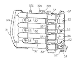
図2〜図7は、上記のような船外機1のトップカウリング2内に設置されているエンジン5を示すもので、図2は、左側方から見たものであり、図3は、右側方から見たものであり、図4は、前方から見たものであり、図5は、後方から一部を切り欠いて見たものであり、図6は、シリンダ軸心に沿ったエンジン本体の横断面と吸気通路の横断面について上方から見たものであり、図7は、シリンダ隔壁に沿ったエンジン本体の横断面と吸気通路の横断面について上方から見たものである。
【0013】
エンジン5は、縦方向に各気筒が配列されている4サイクル4気筒エンジンであって、ヘッドカバー11とシリンダヘッド12とシリンダブロック13とクランクケース14を順次船体の前後方向に沿って一体的に連結することでその本体部分が構成されており、クランクケース14が前側となりヘッドカバー11が後側となるように配置されている。
【0014】
シリンダヘッド12の左側には、上下方向に間隔をおいて重なるように各気筒の吸気ポート15がそれぞれ形成され、シリンダヘッド12の右側には、上下方向に間隔をおいて重なるように各気筒の排気ポート16がそれぞれ形成されていて、各吸気ポート15に対して吸気バルブ17が、また、各排気ポートに対して排気バルブ18がそれぞれ設置されている。
【0015】
そして、各気筒の吸気バルブ17と排気バルブ18をそれぞれ駆動するための吸気側カム軸19と排気側カム軸20が、ヘッドカバー11で覆われたカム室21内で、シリンダヘッド12とカムキャップ22により挟持された状態で、回転軸線方向が上下方向となるようにそれぞれ軸支されていて、各カム軸19,20の上端部には、カムプーリー23,24がそれぞれ固定されている。
【0016】
シリンダブロック13とクランクケース14によって画成されているクランク室25には、各気筒に共通するクランク軸6が、回転軸線方向が上下方向となるように軸支されており、クランク軸6の上端部にはフライホイール26が固定されていて、クランク軸6のフライホイール26よりも下方に固定されたタイミングプーリー27と各カムプーリー23,24とに渡って、クランク軸6の回転を各カム軸19,20に伝動させるためのタイミングベルト28が掛け渡されている。
【0017】
なお、タイミングベルト28に対しては、図示していないが、常にタイミングベルト28を内側に押圧する方向に付勢することでその弛みを防ぐためのテンショナーが設置されており、フライホイール26や各カムプーリー23,24やタイミングベルト28などを上方から覆うように、トップカウリング2の内側に更にカバー部材29が設けられている。
【0018】
エンジン本体のクランクケース14よりも前方には、吸気通路の空気導入部となるサージタンク31が設置されており、縦長に形成されたサージタンク31には、サージタンク31の底部よりも若干上方の位置で右側方に縦長の吸気口31aが開口されていて、サージタンク31の後部左側からは、エンジン本体の左側を通り、シリンダヘッド12の左側面に開口された各吸気ポート15に向かって、上下方向に間隔を置いて横方向に並列して配置された4本の吸気管32が、上方から見て重なるようにそれぞれ略水平方向に延ばされている。
【0019】
サージタンク31から延びる各吸気管32の吸気下流側の端部は、それぞれキャブレター33の吸気上流側に接続されており、各キャブレター33の吸気下流側は、キャブレター33から吸気ポート15に至る曲がった短い4本の吸気管を上下方向に間隔を置いて並列的に連結したインテークマニホールド34により、シリンダヘッド12の各吸気ポート15とそれぞれ接続されていて、それにより、サージタンク31の吸気口31aから吸気管32,キャブレター33,インテークマニホールド34を通って吸気ポート15から燃焼室35に至る各気筒の吸気通路が形成されている。
【0020】
サージタンク31と各吸気管32の部分は、本実施形態では、図8に示すように、サージタンク31から各吸気管32の一部(上流部分)までが、吸気通路の中心線(上方から見た幅方向の中心線)に沿って左右に分割された状態となるように、合成樹脂により二つの部材をそれぞれ別個に一体成形してから、それらの部材同士を合わせて結合することにより形成されているもので、サージタンク31の底部と最下位置の吸気管32の底部とは、図9に示すように、ドレーン孔を有することなく滑らかに続くように形成されていて、一方の部材で一体成形された円筒部となっている各吸気管32の下流部分は、その端部で上下方向に間隔をおいて一体的に連結されている。
【0021】
上記のように一体的に結合されたサージタンク31と各吸気管32に対して、図9に示すように、更に各キャブレター33とインテークマニホールド34を一体的に連結することで、サージタンク31からインテークマニホールド34までの各気筒の吸気通路は一つのユニットとして予め一体的に組付けられ、そのようなユニットがエンジン本体の左側面に取り付けられることとなる。
【0022】
その際のユニットの取り付け手順については、先ず、最上位置の吸気管32に一体成形されたハンガー部分32aによってユニットを吊り下げた状態で移動させてエンジン本体に近接させ、次いで、インテークマニホールド34の基部の上端付近と下端付近の各位置に固定された位置決め用のピン51(および、それに対応してシリンダヘッド12の各位置に形成されたピン孔と)によりエンジン本体に対して位置決めしてから、更に、インテークマニホールド34の基部に位置する取付部でボルト52により、また、サージタンク31の近傍で各吸気管32の間に位置する取付部でボルト53により、それぞれエンジン本体に対して固着することとなる。
【0023】
なお、図8および図9に示すように、最上位置の吸気管32には、ハンガー部分32a以外にも、コード案内用の孔部を設けたコード案内部分32b,32cがそれぞれ一体的に形成されており、ハンガー部分32aは、ユニット全体の重心位置の上方近傍に位置し、一方のコード案内部分32bと一体化されていて、ユニットをエンジン本体に取り付けた後には、ハンガー部分32a自体もコードの案内部として使用できるものとなっている。
【0024】
一方、シリンダヘッド12の右側には、各気筒の燃焼室35にそれぞれ一端が開口するように、各気筒の排気ポート16が上下方向で間隔を置いてそれぞれ形成されており、各排気ポート16の他端の開口部に対して、それらを一本に集合させてエンジン本体の下方に排気ガスを排出するための排気通路36が、各シリンダ孔37の右側でシリンダブロック13に一体的に形成されていて、シリンダブロック13内で上下方向に延びる排気通路36は、その下端がエキゾーストガイド41の排気通路に接続されている。
【0025】
また、排気通路36とは反対側のエンジン本体左側(吸気側)には、上下方向で隣合う各気筒の隔壁の位置において、図7に示すように、シリンダブロック13からシリンダヘッド12に渡って、クランク室25とカム室21を連通するようにブローバイガス通路38,39が形成されている。
【0026】
そして、ヘッドカバー11の排気側でカム室21と連通するように設けられたブローバイ室42からは、ブローバイガスを吸気通路に戻すためのブローバイホース43が、エンジン本体の右側でタイミングベルト28の外側に沿うようにサージタンク31に向かって延ばされ、ブローバイホース43の末端は、サージタンク31の側方に開口された縦長の吸気口31aの上端部に上方から接続されている。
【0027】
それにより、燃焼室35からクランク室25側に漏れたブローバイガスは、エンジン本体のシリンダブロック13とシリンダヘッド12の吸気側にそれぞれ形成されたブローバイガス通路38,39を通り、カム室21内を吸気側から排気側に流れてから、ブローバイ室42からブローバイホース43を通ってサージタンク31の吸気口31aの上端部に上方から戻されることとなる。
【0028】
なお、エンジン5には、吸気側のヘッドカバー11の部分に、各キャブレター33に対して燃料を圧送するための2個の燃料ポンプ44が上下方向に並設されており、クランクケース14の前面に、その前側(サージタンク31との間)をカバー部材45で覆った状態で、コントロールユニット46やレクチファイヤーレギュレーター47が設置されており、吸気管32やキャブレター33が設置された側とは反対側(右側面)に、スターターモーター48やオイルフィルター49が設置されている。
【0029】
ところで、上記のような船外機用エンジン5におけるブローバイガス還元構造については、既に述べたように、エンジン本体の吸気側に形成されたブローバイガス通路38,39を通ってカム室21に送られたブローバイガスが、エンジン本体のクランクケース14よりも前方に設置された縦長のサージタンク31に対して、カム室21の排気側に設けられたブローバイ室42から、ブローバイホース43により、タイミングベルト28の外側に沿うようにエンジン本体の右側(排気側)を通って、サージタンク31の側方に開口された縦長の吸気口31aの上端部に上方から送り込まれるようなものとなっている。
【0030】
上記のようなブローバイガス還元構造を備えた本実施形態の船外機用エンジン5によれば、クランク室25内のブローバイガスは、エンジン本体の吸気側に形成されたブローバイガス通路38,39を通ってカム室21の吸気側に入り、更に、カム室21内を吸気側から排気側に流れてから、排気側でブローバイ室42に流れ込むことから、吸気側にブローバイホース43が配管されている場合と比べて、カム室21内を流れる分だけエンジン本体内でのブローバイガスの流路が長くなっており、それによって、ブローバイガスの中に混入しているオイルを分離し易いものとなっている。
【0031】
また、カム室21の排気側に設けられたブローバイ室42から、クランクケース14よりも前方に設置されたサージタンク31に対して、吸気管32やキャブレター33が設置されている側とは反対側の排気側で、タイミングベルト28の外側に沿うようにブローバイホース43を通していることで、ブローバイ室42からサージタンク31までのブローバイホース43の配管が、遠回りして長くなるようなことなく、無駄のない短いものとなっている。
【0032】
そして、ブローバイホース43がサージタンク31の吸気口31aの近傍に接続されていることで、吸気口31aから吸い込まれた吸気の流れに乗って、ブローバイガスが各吸気管32に分配され、特に、本実施形態では、サージタンク31の側方に開口された縦長の吸気口31aに対して、その上端部に上方からブローバイホース43が接続されていることで、ブローバイホース43からのブローバイガスの流出方向とブローバイガス自体の重力とにより、ブローバイガスが下方の吸気管32にまで効果的に分配されることとなる。
【0033】
【発明の効果】
以上説明したような本発明の船外機用エンジンのブローバイガス還元構造によれば、ブローバイホースの配管を、遠回りして長くなるようなことなく、無駄のない短いものとして、しかも、ブローバイホースを通してサージタンクに戻すブローバイガスを各気筒の吸気管に対して効果的に分配することができる。
【図面の簡単な説明】
【図1】本発明のブローバイガス還元構造を備えたエンジンが搭載されている船外機の概略を示す左側から見た側面図。
【図2】図1に示した船外機のトップカウリング内に収納されているエンジンを示す左側から見た側面図。
【図3】図2に示したエンジンの右側から見た側面図。
【図4】図2に示したエンジンの前方から見た前面図。
【図5】図2に示したエンジンの後方から見た一部切り欠き後面図。
【図6】図2に示したエンジンのシリンダ軸心に沿ったエンジン本体の横断面と吸気通路の横断面を示す部分断面上面図。
【図7】図2に示したエンジンのシリンダ隔壁に沿ったエンジン本体の横断面と吸気通路の横断面を示す部分断面上面図。
【図8】図2に示したエンジンに取り付けられる吸気通路のユニットを示す一部切欠き上面図。
【図9】図8に示した吸気通路のユニットの一部切欠き側面図。
【符号の説明】
1 船外機
5 エンジン
6 クランク軸
11 ヘッドカバー(エンジン本体)
12 シリンダヘッド(エンジン本体)
13 シリンダブロック(エンジン本体)
14 クランクケース(エンジン本体)
21 カム室
31 サージタンク
31a 吸気口
32 吸気管
38 ブローバイガス通路(シリンダブロックの)
39 ブローバイガス通路(シリンダヘッドの)
42 ブローバイ室
43 ブローバイホース[0001]
BACKGROUND OF THE INVENTION
The present invention relates to a multi-cylinder engine mounted on an outboard motor of a small boat, and more particularly to a blow-by gas reduction structure for returning blow-by gas to an intake passage in such an outboard motor engine.
[0002]
[Prior art]
For multi-cylinder engines mounted on outboard motors of small vessels, the cylinder axial direction of each cylinder is usually the front-and-rear direction of the fuselage so that the crankcase side is the front and the cylinder head side is the rear. It is installed in the top cowling at the top of the outboard motor with the common crankshaft in the vertical direction of the fuselage and the cylinders of the engine main body arranged vertically. From the vertically long surge tank, the intake pipes of the cylinders arranged at intervals in the up-down direction are approximately directed toward the cylinder head at the rear of the engine body so that the carburetor is installed in the middle. It is extended horizontally.
[0003]
In such an engine for an outboard motor, conventionally, a surge tank is disposed on the front side of the engine body (side of the crankcase), so that the blow-by gas is drawn into the intake passage from the blow-by chamber communicating with the cam chamber. The blow-by hoses for returning to the engine were placed at intervals in the vertical direction through the intake side of the engine so that the piping would not be long due to a detour and passed between the engine body and the carburetor. The part between the intake pipes is connected to the surge tank from the rear.
[0004]
[Problems to be solved by the invention]
By the way, in the conventional engine for an outboard motor as described above, the blow-by hose is surged in a direction so as to face the flow of intake air near any one of the intake pipes spaced apart in the vertical direction. By being connected to the tank from behind, the blow-by gas returned from the blow-by hose to the surge tank is difficult to be distributed to the intake pipe of each cylinder.
[0005]
The present invention is intended to solve the above problems, and specifically, for the blow-by gas reduction structure of the engine for an outboard motor, without increasing the length of the piping of the blow-by hose, The blow-by gas returned from the blow-by hose to the surge tank is easily distributed to the intake pipe of each cylinder.
[0006]
[Means for Solving the Problems]
In order to solve the above-described problems, the present invention is configured so that each cylinder is longitudinally arranged so that the crank axis is in the vertical direction of the fuselage and the cylinder axis is in the longitudinal direction of the fuselage. The intake pipes of the cylinders arranged at intervals in the vertical direction are extended toward the cylinder head at the rear of the engine body from the vertically long surge tank arranged in front of the engine body arranged in In an engine for an outboard motor, a blow-by hose for returning blow-by gas to the intake passage is provided on the opposite side of each intake pipe from the blow-by chamber provided on the exhaust side of the cam chamber at the rear of the engine body. It is characterized by being connected to the vicinity of the intake port of the surge tank through the exhaust side.
[0007]
Further, in the blow-by gas reduction structure for an outboard engine described in claim 1, as described in
[0008]
Furthermore, in the blow-by gas reduction structure for an outboard engine described in
[0009]
DETAILED DESCRIPTION OF THE INVENTION
Embodiments of the blow-by gas reduction structure for an outboard motor engine of the present invention will be described below with reference to the drawings.
[0010]
FIG. 1 shows an outboard motor equipped with an engine having a blow-by gas reduction structure according to the present invention. The outboard motor 1 is connected to a top cowling 2, an
[0011]
A drive shaft 7 connected to the lower end of the
[0012]
2 to 7 show the
[0013]
The
[0014]
An
[0015]
The
[0016]
In the
[0017]
Although not shown in the figure for the
[0018]
In front of the
[0019]
The end of each
[0020]
In this embodiment, as shown in FIG. 8, the portion of the
[0021]
As shown in FIG. 9, the
[0022]
As for the procedure for attaching the unit at that time, first, the unit is moved in a suspended state by a
[0023]
As shown in FIGS. 8 and 9, the
[0024]
On the other hand, on the right side of the
[0025]
Further, on the left side (intake side) of the engine body opposite to the
[0026]
A blow-by
[0027]
As a result, blow-by gas leaked from the
[0028]
In the
[0029]
By the way, as described above, the blow-by gas reduction structure in the
[0030]
According to the
[0031]
Further, from the blow-
[0032]
The blow-by
[0033]
【The invention's effect】
According to the blow-by gas reduction structure for an outboard engine of the present invention as described above, the piping of the blow-by hose can be made short without waste, without being wasteful, and through the blow-by hose. The blow-by gas returned to the surge tank can be effectively distributed to the intake pipe of each cylinder.
[Brief description of the drawings]
FIG. 1 is a side view showing an outline of an outboard motor on which an engine having a blow-by gas reduction structure of the present invention is mounted, as viewed from the left side.
FIG. 2 is a side view showing the engine housed in the top cowling of the outboard motor shown in FIG. 1 as viewed from the left side.
FIG. 3 is a side view of the engine shown in FIG. 2 as viewed from the right side.
4 is a front view of the engine shown in FIG. 2 as viewed from the front. FIG.
5 is a partially cutaway rear view seen from the rear of the engine shown in FIG. 2. FIG.
6 is a partial cross-sectional top view showing the cross section of the engine body and the cross section of the intake passage along the cylinder axis of the engine shown in FIG. 2;
7 is a partial cross-sectional top view showing the cross section of the engine body and the cross section of the intake passage along the cylinder partition wall of the engine shown in FIG. 2;
8 is a partially cutaway top view showing a unit of an intake passage attached to the engine shown in FIG. 2. FIG.
9 is a partially cutaway side view of the unit of the intake passage shown in FIG. 8. FIG.
[Explanation of symbols]
1
12 Cylinder head (engine body)
13 Cylinder block (engine body)
14 Crankcase (engine body)
21
39 Blow-by gas passage (for cylinder head)
42 Blow-by
Claims (3)
Priority Applications (2)
| Application Number | Priority Date | Filing Date | Title |
|---|---|---|---|
| JP26811597A JP3897197B2 (en) | 1997-09-12 | 1997-09-12 | Blow-by gas reduction structure for outboard engine |
| US09/140,153 US5899197A (en) | 1997-09-12 | 1998-08-26 | Crankcase ventillation for outboard motor |
Applications Claiming Priority (1)
| Application Number | Priority Date | Filing Date | Title |
|---|---|---|---|
| JP26811597A JP3897197B2 (en) | 1997-09-12 | 1997-09-12 | Blow-by gas reduction structure for outboard engine |
Publications (2)
| Publication Number | Publication Date |
|---|---|
| JPH1181971A JPH1181971A (en) | 1999-03-26 |
| JP3897197B2 true JP3897197B2 (en) | 2007-03-22 |
Family
ID=17454103
Family Applications (1)
| Application Number | Title | Priority Date | Filing Date |
|---|---|---|---|
| JP26811597A Expired - Lifetime JP3897197B2 (en) | 1997-09-12 | 1997-09-12 | Blow-by gas reduction structure for outboard engine |
Country Status (2)
| Country | Link |
|---|---|
| US (1) | US5899197A (en) |
| JP (1) | JP3897197B2 (en) |
Families Citing this family (21)
| Publication number | Priority date | Publication date | Assignee | Title |
|---|---|---|---|---|
| JP3900389B2 (en) * | 1997-09-12 | 2007-04-04 | ヤマハマリン株式会社 | Intake passage mounting structure for outboard engine |
| JP3969549B2 (en) * | 1997-09-12 | 2007-09-05 | ヤマハマリン株式会社 | Intake passage structure for outboard engine |
| AUPP191698A0 (en) * | 1998-02-20 | 1998-03-12 | Orbital Engine Company (Australia) Proprietary Limited | Treatment of engine blow-by gases |
| JP3963292B2 (en) * | 1998-04-24 | 2007-08-22 | ヤマハマリン株式会社 | Outboard engine |
| JP2000073734A (en) | 1998-08-26 | 2000-03-07 | Sanshin Ind Co Ltd | Four-cycle engine |
| JP4107455B2 (en) | 1998-12-25 | 2008-06-25 | ヤマハマリン株式会社 | Multi-cylinder engine for outboard motor |
| JP2000310118A (en) * | 1999-04-27 | 2000-11-07 | Sanshin Ind Co Ltd | Silencer device for outboard motor |
| JP2001065412A (en) | 1999-08-26 | 2001-03-16 | Sanshin Ind Co Ltd | Engine |
| JP2001107740A (en) | 1999-10-04 | 2001-04-17 | Sanshin Ind Co Ltd | Four-cycle engine |
| JP2001173455A (en) * | 1999-12-20 | 2001-06-26 | Sanshin Ind Co Ltd | Four-cycle engine |
| US6295963B1 (en) * | 2000-10-09 | 2001-10-02 | Brunswick Corporation | Four cycle engine for a marine propulsion system |
| US6739313B2 (en) | 2000-10-11 | 2004-05-25 | Yamaha Marine Kabushiki Kaisha | Air induction system for multi-cylinder engine |
| JP4391003B2 (en) | 2000-11-07 | 2009-12-24 | ヤマハ発動機株式会社 | Outboard motor |
| JP4259744B2 (en) | 2000-11-27 | 2009-04-30 | ヤマハ発動機株式会社 | Fuel supply system for 4-cycle engine for outboard motor |
| US6915771B2 (en) | 2001-02-07 | 2005-07-12 | Yamaha Marine Kabushiki Kaisha | Battery cable layout for outboard motor |
| US6453892B1 (en) * | 2001-10-11 | 2002-09-24 | Dana Corporation | Constrained layer damped steel baffle |
| USD512074S1 (en) * | 2004-01-27 | 2005-11-29 | Lee Frederick Bender | Auto intake plenum |
| USD533189S1 (en) | 2005-04-11 | 2006-12-05 | C & L Performance, Inc. | Inlet pipe |
| JP4679557B2 (en) * | 2007-09-10 | 2011-04-27 | 本田技研工業株式会社 | Internal combustion engine with intake parts |
| EP2072796B1 (en) | 2007-09-10 | 2012-09-19 | Honda Motor Co., Ltd. | Air cleaner device for internal combustion engine and internal combustion engine |
| DE102016008299B4 (en) * | 2016-07-06 | 2020-12-31 | Neander Motors Ag | Oil separator for an internal combustion engine |
Family Cites Families (3)
| Publication number | Priority date | Publication date | Assignee | Title |
|---|---|---|---|---|
| EP0458341A1 (en) * | 1990-05-24 | 1991-11-27 | Mazda Motor Corporation | Cylinder head structure of DOHC engine |
| JP3450026B2 (en) * | 1993-04-15 | 2003-09-22 | ヤマハマリン株式会社 | Ship propulsion |
| GB9501713D0 (en) * | 1995-01-28 | 1995-03-15 | Rover Group | A breather system for an internal combustion engine |
-
1997
- 1997-09-12 JP JP26811597A patent/JP3897197B2/en not_active Expired - Lifetime
-
1998
- 1998-08-26 US US09/140,153 patent/US5899197A/en not_active Expired - Lifetime
Also Published As
| Publication number | Publication date |
|---|---|
| JPH1181971A (en) | 1999-03-26 |
| US5899197A (en) | 1999-05-04 |
Similar Documents
| Publication | Publication Date | Title |
|---|---|---|
| JP3897197B2 (en) | Blow-by gas reduction structure for outboard engine | |
| JP3608637B2 (en) | Outboard motor | |
| JP3969549B2 (en) | Intake passage structure for outboard engine | |
| JP3879943B2 (en) | Outboard motor | |
| JP2001098950A (en) | Outboard engine | |
| JP4583339B2 (en) | Vertical internal combustion engine having a belt-type transmission mechanism | |
| JP3184360B2 (en) | Breather structure of outboard motor | |
| JP3900389B2 (en) | Intake passage mounting structure for outboard engine | |
| JP2001107740A (en) | Four-cycle engine | |
| JP3971842B2 (en) | Outboard motor | |
| JPH10238325A (en) | Oil pump structure for engine for outboard motor | |
| JPH1162545A (en) | Blow-by gas reducing device of double overhead-camshaft type engine for outboard motor | |
| JP2000310118A (en) | Silencer device for outboard motor | |
| US6516768B1 (en) | Four-cycle engine | |
| JP2001115851A (en) | Outboard motor | |
| JP3690869B2 (en) | Air passage structure of outboard motor | |
| JP3963084B2 (en) | 4-cycle engine for outboard motor | |
| JP4007463B2 (en) | Intake passage structure for outboard engine | |
| JP4583337B2 (en) | Vertical internal combustion engine having a belt-type transmission mechanism | |
| JP2001082124A (en) | Outboard motor | |
| JP3023815B2 (en) | 4-cycle engine intake system | |
| JP3854230B2 (en) | Intake device for outboard engine | |
| US7263958B2 (en) | Valve drive mechanism in an internal combustion engine | |
| JP3800444B2 (en) | Outboard motor | |
| JP4161774B2 (en) | Camshaft support structure in a 4-cycle engine |
Legal Events
| Date | Code | Title | Description |
|---|---|---|---|
| A621 | Written request for application examination |
Free format text: JAPANESE INTERMEDIATE CODE: A621 Effective date: 20040906 |
|
| A977 | Report on retrieval |
Free format text: JAPANESE INTERMEDIATE CODE: A971007 Effective date: 20061127 |
|
| TRDD | Decision of grant or rejection written | ||
| A01 | Written decision to grant a patent or to grant a registration (utility model) |
Free format text: JAPANESE INTERMEDIATE CODE: A01 Effective date: 20061214 |
|
| A61 | First payment of annual fees (during grant procedure) |
Free format text: JAPANESE INTERMEDIATE CODE: A61 Effective date: 20061214 |
|
| R150 | Certificate of patent or registration of utility model |
Free format text: JAPANESE INTERMEDIATE CODE: R150 |
|
| FPAY | Renewal fee payment (event date is renewal date of database) |
Free format text: PAYMENT UNTIL: 20100105 Year of fee payment: 3 |
|
| S111 | Request for change of ownership or part of ownership |
Free format text: JAPANESE INTERMEDIATE CODE: R313111 |
|
| FPAY | Renewal fee payment (event date is renewal date of database) |
Free format text: PAYMENT UNTIL: 20100105 Year of fee payment: 3 |
|
| R371 | Transfer withdrawn |
Free format text: JAPANESE INTERMEDIATE CODE: R371 |
|
| S111 | Request for change of ownership or part of ownership |
Free format text: JAPANESE INTERMEDIATE CODE: R313111 |
|
| FPAY | Renewal fee payment (event date is renewal date of database) |
Free format text: PAYMENT UNTIL: 20100105 Year of fee payment: 3 |
|
| R350 | Written notification of registration of transfer |
Free format text: JAPANESE INTERMEDIATE CODE: R350 |
|
| FPAY | Renewal fee payment (event date is renewal date of database) |
Free format text: PAYMENT UNTIL: 20100105 Year of fee payment: 3 |
|
| FPAY | Renewal fee payment (event date is renewal date of database) |
Free format text: PAYMENT UNTIL: 20110105 Year of fee payment: 4 |
|
| FPAY | Renewal fee payment (event date is renewal date of database) |
Free format text: PAYMENT UNTIL: 20120105 Year of fee payment: 5 |
|
| FPAY | Renewal fee payment (event date is renewal date of database) |
Free format text: PAYMENT UNTIL: 20130105 Year of fee payment: 6 |
|
| FPAY | Renewal fee payment (event date is renewal date of database) |
Free format text: PAYMENT UNTIL: 20130105 Year of fee payment: 6 |
|
| R250 | Receipt of annual fees |
Free format text: JAPANESE INTERMEDIATE CODE: R250 |
|
| R250 | Receipt of annual fees |
Free format text: JAPANESE INTERMEDIATE CODE: R250 |
|
| R250 | Receipt of annual fees |
Free format text: JAPANESE INTERMEDIATE CODE: R250 |
|
| R250 | Receipt of annual fees |
Free format text: JAPANESE INTERMEDIATE CODE: R250 |
|
| EXPY | Cancellation because of completion of term |