JP3891335B2 - Navigation device - Google Patents
Navigation device Download PDFInfo
- Publication number
- JP3891335B2 JP3891335B2 JP2001334814A JP2001334814A JP3891335B2 JP 3891335 B2 JP3891335 B2 JP 3891335B2 JP 2001334814 A JP2001334814 A JP 2001334814A JP 2001334814 A JP2001334814 A JP 2001334814A JP 3891335 B2 JP3891335 B2 JP 3891335B2
- Authority
- JP
- Japan
- Prior art keywords
- mobile
- communication
- information
- wireless communication
- displayed
- Prior art date
- Legal status (The legal status is an assumption and is not a legal conclusion. Google has not performed a legal analysis and makes no representation as to the accuracy of the status listed.)
- Expired - Fee Related
Links
- 238000004891 communication Methods 0.000 claims description 226
- 230000002093 peripheral effect Effects 0.000 claims description 10
- 238000000034 method Methods 0.000 description 48
- 230000005540 biological transmission Effects 0.000 description 17
- 238000004364 calculation method Methods 0.000 description 15
- 238000010586 diagram Methods 0.000 description 8
- 230000000694 effects Effects 0.000 description 8
- 230000006870 function Effects 0.000 description 5
- 230000005236 sound signal Effects 0.000 description 5
- 238000010295 mobile communication Methods 0.000 description 4
- 238000006243 chemical reaction Methods 0.000 description 2
- 230000009365 direct transmission Effects 0.000 description 2
- 238000012905 input function Methods 0.000 description 2
- 238000006424 Flood reaction Methods 0.000 description 1
- 230000001174 ascending effect Effects 0.000 description 1
- 238000010276 construction Methods 0.000 description 1
- 238000001514 detection method Methods 0.000 description 1
- 239000011159 matrix material Substances 0.000 description 1
- 206010037844 rash Diseases 0.000 description 1
- 230000008054 signal transmission Effects 0.000 description 1
Images


Landscapes
- Traffic Control Systems (AREA)
- Position Fixing By Use Of Radio Waves (AREA)
- Instructional Devices (AREA)
- Navigation (AREA)
- User Interface Of Digital Computer (AREA)
Description
【0001】
【発明の属する技術分野】
本発明は、複数個の移動体間で無線通信により位置情報の交換を行うためのナビゲーション装置に関する。
【0002】
【従来の技術】
GPSによる位置検出技術を利用したナビゲーション装置を用いて、自動車等の移動体に対して目的地までの経路誘導を行うことが広く行われている。近年、このようなナビゲーション装置と通信装置とを接続した移動体通信装置をそれぞれ搭載した複数の移動体間において、互いの位置情報やメッセージ等を交換し、表示する手法が提案されている。
【0003】
特に、地震、風水害、火山噴火等の災害救助活動の際には、災害現場で救助にあたる作業者は、他の作業者と連携を図るために、各作業者の位置情報を互いに正確に把握する必要がある。また、近年、政府や地方自治体の災害救助活動以外に、NGO(非政府組織)やNPO(非営利組織)によるボランティア活動が重要視されつつあり、こうした災害救助活動にも各作業者の位置情報を正確に、且つ、迅速に知り得る通信手段の構築が求められている。
【0004】
例えば、特開平10−62190号では、複数の移動体がグループで移動するとき、互いの位置を相互に確認したい場合や、移動体がはぐれてしまった場合等のように、自位置情報のみならず、予め定めた特定の移動体についても位置情報を得ることができる無線ナビゲーション装置が開示されている。
【0005】
【発明が解決しようとする課題】
特開平10−62190号で開示される無線ナビゲーション装置では、他移動体との無線通信により得られた受信データに基づいて通信可能な移動体をサーチし、サーチ結果をメモリーに記憶し、通信時にはメモリーから読み出した通信可能な移動体名を表示部に表示して、表示部の表示に基づいて通信相手を選択するというものである。しかしながら、このような無線ナビゲーション装置では、表示部には通信可能な移動体のリストだけが表示されるものであり、移動体の位置や進行方向が直感的に分かり難く、位置等の情報を視覚的に正確で、且つ、迅速に把握することができないという問題があった。さらには、表示部には、無線通信可能な相手移動体だけが表示されるため、通信可能な範囲外に位置する他の移動体の位置情報等の把握が不可能であった。
【0006】
そこで、本発明の目的は、地図上に移動体の位置等を示すアイコン、絵文字、シンボル等の標識を表示して、直感的に移動体の位置等の情報の把握を容易にするナビゲーション装置を提供することにある。また、本発明の他の目的は、そのアイコン等に触れるだけで、選択的に相手移動体を呼び出して通信することを可能とするナビゲーション装置を提供することにある。また、本発明のさらなる目的は、通信可能範囲外の移動体の位置等の情報を、他の周辺移動体を中継して入手することで、全ての移動体間の情報交換を可能とするナビゲーション装置を提供することにある。
【0007】
【課題を解決するための手段】
請求項1記載の発明は、複数の移動体間において、無線通信により情報交換を行う機能を有するナビゲーション装置において、地図画面上に無線通信可能な他移動体を識別可能な標識を用いて表示し、前記地図画面上で通信を希望とする他移動体に対応する標識を選択することで、該他移動体との通信を可能とし、タッチパネルを備え、該タッチパネル上で、通信を希望する他移動体の標識に対応する位置を指触することで、該他移動体を選択し通信可能とすると共に、前記標識のうち少なくとも二つの標識が重なって前記地図画面上に表示された場合、重畳箇所付近を指触することで、前記二つの標識が視覚的に識別可能なように自動的に地図縮尺を変化させることを特徴とする。
【0008】
請求項2記載の発明は、複数の移動体間において、無線通信により情報交換を行う機能を有するナビゲーション装置において、地図画面上に無線通信可能な他移動体を識別可能な標識を用いて表示し、前記地図画面上で通信を希望とする他移動体に対応する標識を選択することで、該他移動体との通信を可能とし、タッチパネルを備え、該タッチパネル上で、通信を希望する他移動体の標識に対応する位置を指触することで、該他移動体を選択し通信可能とすると共に、前記標識のうち少なくとも二つの標識が重なって地図画面上に表示された場合、重畳箇所付近を指触することで、前記地図画面上に前記重なり標識により各々表される移動体の移動体情報がリストとして表示され、さらに、該リスト中の所望の移動体を指触することで、該移動体を選択し、通信可能とすることを特徴とする。
請求項3記載の発明は、請求項1又は2記載の発明において、前記標識はアイコンであることを特徴とする。
【0009】
請求項4記載の発明は、請求項1又は2記載の発明において、各移動体は無線通信により位置情報を含むステータス情報を相互に交換しており、他の移動体から受信した位置情報を含むステータス情報に基づいて、該他移動体を前記識別可能な標識を用いて前記地図画面上に表示することを特徴とする。
【0010】
請求項5記載の発明は、請求項4記載の発明において、前記ステータス情報は、前記他移動体の位置情報に加えて、前記他移動体の移動方向、移動速度および識別情報を含むことを特徴とする。
【0011】
請求項6記載の発明は、請求項5記載の発明において、前記ステータス情報に含まれる識別情報に基づいて、前記他移動体の固有名称が、前記標識と共に前記地図画面上に表示されることを特徴とする。
【0012】
請求項7記載の発明は、請求項5記載の発明において、前記ステータス情報に含まれる移動方向は、該移動方向に応じて向きが可変な矢印を用いて前記地図画面上に表示されることを特徴とする。
【0013】
請求項8記載の発明は、請求項5記載の発明において、前記ステータス情報に含まれる移動速度は、該移動速度に応じて長さが可変な矢印を用いて前記地図画面上に表示されることを特徴とする。
【0017】
請求項9記載の発明は、請求項4記載の発明において、各移動体は、該移動体のステータス情報を、他の移動体から受信したステータス情報と合わせて送信することを特徴とする。
【0018】
請求項10記載の発明は、請求項1又は2記載の発明において、通信不能範囲に位置する移動体との通信を希望する場合には、該移動体との通信状態に応じて、該移動体への通信を中継し得る周辺移動体を探索し、中継動作が可能な周辺移動体が探索された場合に、該周辺移動体を介して前記移動体へ通信を行うことを特徴とする。
【0019】
請求項11記載の発明は、請求項1又は2記載の発明において、前記移動体間における通信は、通信方式としてTDMA方式を用いて行われることを特徴とする。
【0020】
【発明の実施の形態】
以下、本発明の実施形態を添付図面を参照して説明する。
【0021】
図1は本実施形態の移動体間通信装置を備え、各移動体(二輪車、自動車等)に搭載された車載システム1と、各車載システム1と有線もしくは無線で通信可能に接続された外部通信機器(携帯電話、公衆電話網等のネットワーク、ヘッドセットシステム、他の移動体に搭載された車載システム等)との接続関係を示したブロック図である。
【0022】
図1において、車載システム1は、GPSアンテナからの受信信号に基づいて通常のナビゲーション動作を行うナビゲーション装置2と、外部通信機器と無線通信を行うための第一無線通信装置3,第二無線通信装置4および外部通信機器と有線通信を行うための有線通信装置5とを有している。
また、図中、▲1▼は各移動体に搭載された車載システム1間の第二無線通信装置4を介した無線通信による接続を示し、▲2▼は車載システム1と携帯電話との無線通信による接続を示し、▲3▼は携帯電話と車載システム1との有線通信による接続を示し、▲4▼は携帯電話と公衆電話網との基地局を介した無線通信による接続を示し、▲5▼は車載システム1に備えられた有線通信装置5と公衆電話網等のネットワークとの有線通信による接続を示し、▲6▼は車載システムとヘッドセットシステムとの第一無線通信装置3、6を介した無線通信による接続を示している。ヘッドセットシステムは、移動体の利用者が、移動体から所定距離以内離れたときに、移動体に搭載された車載システム1との無線通信を介して外部と通信するためのものである。
【0023】
車載システムと公衆電話網等との接続により、離れた本部との連絡や、現場の状況を文字・画像等により遠隔地に伝送することが可能となる。その実現方法は二つあり、一つは有線通信装置を利用する方法と、もう一つは携帯電話を利用する方法である。
【0024】
有線通信装置5を利用した接続(▲5▼)では、図1の有線通信装置は通信制御装置(後述)により制御され、車載システムを公衆電話網に接続することを可能とする。有線通信装置5と通信制御装置は、統合していわゆるモデムと呼ばれるものであり、本発明の対象ではないが、災害時通信システムの構成要素である。公衆電話網との接続は、公衆電話の接続コネクタを介して行われる。
【0025】
図1の携帯電話を利用した接続(▲4▼)では、携帯電話と車載システムを有線もしくは無線により接続(▲2▼、▲3▼)し、さらに、携帯電話から公衆電話網への接続により実現される。
【0026】
図2は、ヘッドセットシステムの詳細な構成を示したものである。
【0027】
図2で示されているように、ヘッドセットシステムは、それ自体GPSアンテナと、GPS受信機を備えたものであり、特に、車載システム1の第一無線通信装置3と同様な構成を有する無線通信装置6,I/F部及びカメラ、マイク、ヘッドフォンを一体化した携帯用の音声画像通信セット(ヘッドセット部)とからなる。I/F部は、無線通信装置6で受信された信号のうち、オーディオ信号をヘッドフォンに出力し、利用者への告知情報を表示装置へ出力し、カメラで撮影された映像信号をデジタル信号に変換し、無線通信装置6に送る。また、表示/入力装置は、簡易な表示及び制御情報の入力を可能とする。ヘッドセット部は、利用者が頭部等に装着して携帯し、音声情報の送受信及び画像情報の送信のためのHMI(人・機械間操作インターフェース)を形成する。
【0028】
ヘッドセット部はGPS信号の受信を行うGPSアンテナと、静止画像や動画像を捕捉するカメラと、音声信号を捕捉するマイクと、音声信号の出力を行うヘッドフォンとからなる。また、I/F部は、ヘッドセット部と無線通信装置6との間のインターフェースの役割をする。ヘッドセット部のマイク及びカメラで捕捉された音声信号及び映像信号は、I/F部のA/D(アナログ/デジタル変換部)でデジタル信号に変換され、無線通信装置6に送られる。
【0029】
GPSアンテナで受信されたGPS信号は、GPS受信機で復調され、利用者の位置情報がデジタル信号として無線通信装置6に送られる。
【0030】
無線通信装置6で受信された音声信号は、I/F部のD/A(デジタル/アナログ変換部)でアナログ信号に変換され、ヘッドセット部のヘッドフォンに送られる。I/F部の表示/入力装置は、ヘッドセット部だけでは困難な、通信相手先を設定するような利用者の入力機能、他の作業者の状態(後述するステータス情報)の表示機能、自局ステータス情報(通常/非常など)を設定するような利用者の入力機能等を有する。
【0031】
第一無線通信装置3と第二無線通信装置4とは異なるものが利用される。なぜならば、第一無線通信装置の役割は、一つの車載システムと一つのヘッドセットシステムとの間の通信を行うのみ(つまり、1:1通信)であり、他の車載システムや他のヘッドセットシステムとの通信は不要だからである。
【0032】
ヘッドセットシステムに第二無線通信装置4を利用した場合、第二無線通信装置4は第一無線通信装置3に比べて到達距離を長くする必要があるため、必然的に第二無線通信装置4の送信電力は第一無線通信装置3に比べて大きくなり、大きなバッテリー容量が必要となり、重量が増大し、携帯に不便となるデメリットがある。
【0033】
ヘッドセットシステムは、車載システムから近い距離で利用されるため、第一無線通信装置3の送信電力を小さく抑えることが可能で、バッテリー重量を軽減できるメリットを有する。
【0034】
本実施形態においては、第一無線通信装置3の具体的な構成は本実施形態の対象としないので説明を省略する。以下では、車載システムにおける第二無線通信装置4との連携について説明する。
【0035】
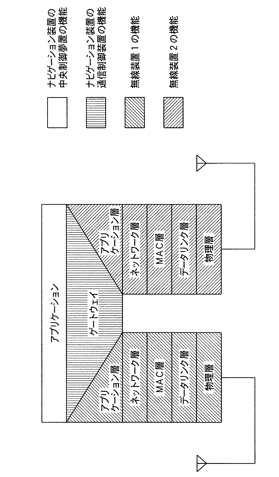
図3は第一無線通信装置3と第二無線通信装置4の層(レイヤ)構造を示す。二つの無線通信装置はゲートウェイにより接続される。ゲートウェイ機能は、ナビゲーション装置の通信制御装置が担うが、どの部分が担うかは特に本実施形態では本質的ではない。また、図3で示される以外に、ネットワーク層で両無線通信装置を接続するルータ機能を用いても良い。
図4は、本実施態様の車載システム1に搭載されるナビゲーション装置2の構成を示したブロック図である。
【0036】
ナビゲーション装置2は、GPSアンテナを介して衛星からのGPS信号を受信するGPS受信装置7と、GPS受信装置7からの信号と、ジャイロ8からの信号と、さらに移動体の車速信号とに基づいて移動体の位置、進行方位等を演算する位置演算装置9とを有する位置標定装置10を備えている。また、ナビゲーション装置2は、キーボード・スイッチ群11、オーディオ入力装置12等を介してナビゲーション動作および通信動作に必要な情報を利用者が入力する入力装置13と、位置標定装置10からの出力信号と、入力装置13からの入力情報と、後述する第一および第二通信制御装置14、15からの通信信号とを入力し、所定の処理を施す中央制御装置16と、中央制御装置16からの処理信号に基づいて画像表示装置17上に画像を表示させたり、オーディオ出力装置18から音声等を出力させる出力装置19とを備えている。
【0037】
中央制御装置16は、位置標定装置10の出力信号と、入力装置13を介して入力された入力情報に所定の処理を施した後、第一通信制御装置14および第二通信制御装置15を介して、第一無線通信装置3,第二無線通信装置4および有線通信装置5へ出力する。これらの通信装置に入力された処理信号は無線もしくは有線により外部通信機器へ送信される。
【0038】
さて、本発明の実施形態は、特に車載システム間の通信方式(▲1▼)にその特徴がある。
【0039】
本実施形態では、各移動体(車載システム)間の通信は、図1で示される第二無線通信装置4により行われている。この第二無線通信装置4とナビゲーション装置とにより各移動体間での位置情報等の情報交換が可能となる。以下、ナビゲーション装置2と第二無線通信装置4とを組み合わせた構成を、移動体間通信装置と称する。
【0040】
以下、移動体間通信装置(第二無線通信装置4)による移動体(車載システム)間の通信について説明する。なお、以下の説明で「移動局」とは、第二無線通信装置4を利用して無線通信を行う車載システムを意味する。また、前述したように、移動体間通信により各移動局間で送受信される情報とは、ナビゲーション装置により得られた各移動局の位置情報等ばかりでなく、利用者が入力装置等により入力した入力情報も含まれている。入力情報は、メッセージ等のテキスト情報、画像音声情報等任意の通信情報を含む。
【0041】
本実施態様では、移動体間の通信は、通信方式としてTDMA(時間分割型多重接続)を用いて行われる。これは、最小数の通信装置(受信装置)を用いて複数の他移動体(車載システム)からの信号を正確に受信するにはTDMA方式が最適であるからである。また、TDMA方式以外の通信方式、例えばCDMA(符号分割型多重接続)方式等を用いるか、又はこれらの通信方式とTDMA方式を組み合わせて利用してもよい。
【0042】
さて、通信方式としてTDMA方式を用いた場合、各第二無線通信装置4への通信スロットの割当が重要となる。ここで、複数個の第二無線通信装置4が互いに信号の送受信を行う場合、各第二無線通信装置4が同時に信号を送信したのでは、信号同士の干渉が生じてしまい、受信側で正確な信号を受信できなくなる。従って、所定の時間周期を適当な数に等分して、各等分された時間間隔を各第二無線通信装置4の信号送信に割り当てることが必要になる。各第二無線通信装置4に割り当てられたこの時間間隔を通信スロットという。各第二無線通信装置4は、割り当てられた時間間隔毎に必要な情報(パケット)を送信することになる。
【0043】
基地局を利用した無線通信方式では、このような通信スロットは基地局により自動的に割り当てられるので、各第二無線通信装置4は何ら通信スロットを気にせずに情報を送信することができるが、基地局を有さない自立系の通信方式を採用した本実施形態では、以下の方法で通信スロットの割り当てが行われる。
【0044】
まず、各第二無線通信装置4には、通信スロットを規定するための認識番号(ID)が予め割り当てられている。このID値に応じて(例えば番号の小さな順に)、各第二無線通信装置4は予めスケジュールされた通信スロットでステータス情報(後述)の送信を行う。スケジュールの方法としては、GPS受信装置7で生成された時間基準による正確な時計を用いることで行われる。例えば車載システムの総台数が10台で、各第二無線通信装置4が使用する最大のパケット長を80msとした場合は、1秒間を10分割し、毎秒の0.1秒時にIDが0001番の第二無線通信装置4が通信スロットを利用してパケットを送信し、毎秒の0.2秒時にIDが0002番の第二無線通信装置4が通信スロットを利用してパケットを送信する。以下同様に、0010番の第二無線通信装置4のパケット送信が終了した後、次の0.1秒時に0001番のIDを持つ第二無線通信装置4によるパケット送信が繰り返し行われる。
【0045】
ここで、GPS信号が受信困難となり、自局の通信スロットが分からなくなった場合は、通信状態にある他の第二無線通信装置4の送信信号を受信してそのID値を読み取り、自局が送信すべき直前の通信スロットによる送信が完了した時点を基準にして送信を行うか、または、このID値に基づいて自局が送信すべき通信スロットの位置(時間)を算出してパケット送信する。
【0046】
複数の車載システム間の通信を成立させるためには、通信を行う車載システム間の無線通信そのものが可能でなければならない。災害救助活動やNGO,NPO等のボランティア活動では、各移動局(車載システム)は必ずしも無線通信可能な位置範囲にいるわけではなく、通信を希望する相手先の移動局(以下、目標移動局と称する)との無線通信を行うことができない場合が多々生じる。
【0047】
このような場合に、本実施形態では、無線通信可能な周辺移動局(車載システム)を中継して、通信接続を希望とするが、実際上通信不可能な目標移動局(車載システム)への通信を実現することができる。周辺移動局には当該移動局との無線接続状態の良いものや悪いものも存在する。このような周辺移動局の中で最適で、最小数の中継移動局を探し出し、これらの中継移動局を介して目標移動局へ情報を送信すれば、無線通信接続が不可能な目標移動局へ必要な情報を正確に、且つ効率的に送信することが可能となる。以下、このような目的を果たすための通信方式について説明する。
【0048】
本実施形態では、各移動局(車載システム)の第二無線通信装置4からはステータス情報(後述)が常時(例えば、割り当てられた固有の通信スロットの周期で)で送信されている。この送信は、特定の第二無線通信装置4宛にではなく一斉同報形式で行われている。すなわち、各第二無線通信装置4からは、他の全ての第二無線通信装置4宛へステータス情報が常時送信されている。各第二無線通信装置4は、他の第二無線通信装置4からのステータス情報を含む信号を受信し、中央制御装置16で、ID毎にその受信品位を記録・比較して、内部の受信品位テーブルを逐次更新する。この受信品位テーブルは目標移動局との通信接続が可能かどうかを判断したり、目標移動局との通信が不可能な場合には、最適な中継移動局を探索するのに利用される。
【0049】
ここで音声情報や画像情報等の、ステータス情報以外に送信すべきイベント(特定の移動局へ送信すべき希望情報)が車載システムに発生した場合は、受信品位テーブルを参照し、パケットのヘッダーに、宛先ID(目標移動局ID)、中継移動局ID(必要な場合)を書き込んで、希望情報とともにパケットとして送信する。中継移動局IDの決定方法については後述する。
また、ステータス情報以外の希望情報を含んだパケットを受信した場合は、その車載システムは、前述の宛先ID、中継移動局IDを読み取り、宛先IDが自分のIDに一致する場合は情報を格納・処理し、中継移動局IDが自分のIDに一致する場合は自ら中継動作を行う。ここで、中継動作とは、最終の宛先ID又は次の中継ID宛に希望情報(宛先ID,他中継IDを含む)をステータス情報と共に送信することを意味する。
【0050】
ステータス情報とは、複数の移動局(車載システム)の第二無線通信装置4間の通信を成立させるための必須情報であり、自局IDと、他局の受信品位情報と、車載システムの動作に必要な、車載システム間で交換すべき情報、すなわち、自局の位置情報、移動速度、移動方向などの情報と、走行中/停車中、乗車中/降車中、通常/非常などの情報とから成る。
【0051】
次に中継移動局IDの決定方法について説明する。
【0052】
中継を行う場合、確実に中継可能な移動局を選定することと、目標移動局への情報到達までに要する遅延時間を最小にするため、中継回数を最小限に抑えることが要求される。
【0053】
本発明においては、他の移動局から常時送信されるパケット(ステータス情報)を受信した際の受信品位を用いて、中継移動局を探索する。今、移動局の総台数(車載システムの総台数)がA,B,C,D,Eの5台であったとする。各移動局の相互位置関係(距離関係)、ビルなどによる遮蔽状態等により、必ず全ての直接通信が成立するわけではない。そこで中継が必要となる。
【0054】
前述したように、ステータス情報には、他の移動局からの信号がどの程度の品位で受信されたかの情報が含まれている。したがって、孤立した移動局が無い限りにおいては、有限回数のステータス情報の受信によって、全ての移動局が他の全ての移動局をどの程度の品位で受信しているかが分かることになる。受信品位は、受信品位のレベルを表した受信品位値として受信品位テーブルに書き込まれ、全ての車載システムで保管・更新される。受信品位としては、受信信号強度、信号対雑音比、受信誤り率、又はこれらを複合した値が用い得る。
【0055】
図5は5台の移動局(A,B,C,D,E)間の通信状態を示したものであり、通信状況に応じて、通信が「良好」、「可能」、「困難」、「不可能」な状態で示されている。
【0056】
いま、ある移動局が目標移動局へ希望情報を送信する際に行う、希望情報の送信プロセスについて図6のフローチャートを用いて説明する。
【0057】
図6は希望情報の送信を希望する移動局は、まず、受信したステータス情報に基づいて作成した受信品位テーブルを参照し(S1)、相手先(目標移動局)と直接通信可能かどうかを判断する(S2)。直接通信可能な場合は、中継移動局IDをヘッダーに書き込まず(中継の指示を出さず)、宛先IDをパケットのヘッダーに書き込み情報を送信する(S3)。一方、直接通信不可能と判断される場合は、中継回数の上限を設定し(S4)、中継移動局の決定プロセスに入る(S5)。中継移動局の決定プロセスにて中継移動局が決定されたならば(通信経路の決定)、宛先IDと中継移動局IDとをヘッダーに書き込んで希望情報を送信する(S6)。一方、中継移動局が決定されない場合は、ステップS1に戻り、新たに受信したステータス情報に基づいて作成された受信品位テーブルを参照し、以後ステップS2からステップS5を繰り返す。
【0058】
いま、図5において、中継回数の上限を2回と定めた上で、A局からB局への通信を行う場合を例として、中継移動局決定プロセスについて説明する。
【0059】
ここで、受信品位値をαn、中継回数をr、αnの最大値をMとして、標価値Γを式(1)で表し、Γが最大のものを通信経路として選択する。
【0060】
【数1】
【0061】
【表1】
【0062】
中継無し(r=0)
A→B:0/5=0 (2)
中継1回(r=1)
A→C→B:(5×3)/25=0.6 (3)
A→D→B:(0×3)/25=0 (4)
A→E→B:(3×2)/25=0.24 (5)
中継2回(r=2)
A→C→D→B:(5×1×3)/125=0.12 (6)
A→C→E→B:(5×1×2)/125=0.08 (7)
A→D→C→B:(0×1×3)/125=0 (8)
A→D→E→B:(0×4×2)/125=0 (9)
A→E→C→B:(3×1×3)/125=0.072 (10)
A→E→D→B:(3×4×3)/125=0.288 (11)
この場合は式(3)のΓ=0.6が最大であり、A→C→Bを通信経路として選択することとなる。
【0063】
なお、特定の一つの相手先に対する通信経路候補数Csは、移動局の局数をNとした場合、式(12)で表され、全ての相手先に対しての通信経路候補数Caは、式(13)で表される。
【0064】
【数2】
【数3】
(1)Γの計算で、αnに一つでもある値以下(例えば、0,1)が含まれていたら、計算を中止する。
【0066】
例えば式(2)から式(11)の計算において、ゼロが一つでも含まれていたら計算を中止することにした場合、式(2)、式(8)、式(9)にゼロが含まれているため、3つのΓの計算に対しては、少なくとも除算を行う必要は無くなる。また、同様に1以下が一つでも含まれていたら計算を中止することにした場合、更に式(6)、式(7)、式(10)が該当するため、合計6つのΓの計算に対して負荷の軽減が図れる。
(2)中間計算値を保存して後の計算で再利用する。
【0067】
例えば、図5において、中継回数を3回(R=3)とすると、A→C→D→E→Bという通信経路が候補の一つになるが、これは、式(6)の結果A→C→DにD→E→Bの新しい計算を付加することで達成できる。
【0068】
本実施態様において、他の通信経路の決定方法としては、ステータス情報に含まれる移動局の位置情報を利用する方法がある。
【0069】
前述したように、ステータス情報として各移動局は自局の位置情報を常時送信している。各移動局は、受信した他の移動局からのステータス情報に含まれる位置情報もステータス情報に含めて送信するようにしておけば、有限回数の受信によって、全ての移動局の位置情報を知ることができる。
【0070】
全ての移動局の位置情報から、移動局間の距離を計算することができる。一般的に、距離が遠ければ通信は困難になり、近ければ通信は容易になるから、距離に応じて表1のようなテーブルを作成することが可能である。そのようにして生成された表(距離テーブル)を同様に用いて通信経路を決定することが出来る。この距離テーブルでは、各移動体間の距離が前述の受信品位値に対応するものであり、移動体間の距離の値に応じて所定のレベルが付されることになる。
【0071】
本実施形態の、更に他の通信経路の決定方法は、中継回数を1回に制限した上で、式(1)のような乗算・除算を行わず、数値の比較によって行うものである。
【0072】
式(1)を用いる場合、各移動局は他局の送信信号を受信して受信品位を記録し、更に他局の送信するステータス情報を受信して、それに含まれる他局での受信品位情報を記録することで初めて表1が完成する。詳しく述べると、例えば、移動局Aが移動局B〜Eを受信して得られる受信品位情報は、表1のAの1列である。次にB局が送信するステータス情報からBの1列が得られ、同様にCからEの列が得られる。完成した表1を、移動局Aは送信するステータス情報に含めて送信する。即ち、移動局の総数がN台とすると、送信する受信品位情報はN×Nのマトリックスとなる。これを全ての移動局が送信するのであるから、全ての受信品位情報の情報量は、N×N×N=N3個となる。
【0073】
これは、中継回数に制限を設けず、あらゆる通信経路の可能性を探索する場合には必要な情報であるが、例えばN=128の場合は2,097,152個の情報量となり、全情報に占めるステータス情報が莫大となり、結果として音声やデータなど、利用者が送信したい情報量を圧迫することになる。更には、式(13)のような計算を必要とし、前記(1)、(2)のような工夫を施したとしても、計算量が膨大になることは避けられない。
【0074】
そこで、以下のようにして通信経路の決定方法を簡略化し、計算量の圧縮とステータス情報の削減が可能である。
中継回数を1回に限定する。
式(1)を用いず、数値の大小比較で通信経路を決定する。
【0075】
(イ)の方法について説明する。
【0076】
まず、各移動局は、前記したと同じように、他局の受信品位テーブルを作成する。例えば移動局Aにとっては、表1のA列の受信品位情報を取得する。また、同時にその情報をすべての他局宛に送信する。一方、移動局Aは他局が同様に送信した受信品位情報を受信する。つまり、表1のB列〜E列の情報を取得する。
【0077】
次に、希望情報の通信経路の決定は以下のように行われる。
【0078】
移動局Aが移動局B宛に送信する場合を例に取ると、先ず移動局B宛に直接送信する可能性を探索する。これには、表1のA列のB行の受信品位値を参照する。この値が予め決めておいたスレッショルド値以上であれば、「直接送信が可能」と判断して送信を行う。例えばスレッショルド値が2以上であるとすると、表2の例では、受信品位値がゼロであるため、「直接送信は不可能」で、「中継を利用する」と判断する。次に、他の移動局が送信するステータス情報に含まれる受信品位情報を参照する。この場合、移動局Bと移動局Dは受信不能であるため、ステータス情報も受信できないが、移動局Cと移動局Eは受信可能であるため、最終的に表2の受信品位テーブルが得られる。
【0079】
【表2】
【0080】
この例では、偶然に式(1)による決定と結果が一致したが、実際には一致しないことの方が多い。即ち、最適通信経路を選択することはできない。また、中継回数は1回に限定されるため、経路が見つからない確率が増大する。しかし、決定のプロセスは極めて簡略であり、掛算・除算も不要であるため、計算量が少なくて済む。また、一つの局が送信する受信品位値情報はN、全移動局が送信する情報量はN2であり、前記の方法に比べると共に1/Nになり、利用者が送信したい情報量を圧迫することも無いという利点を有する。
【0081】
以上の中継経路決定プロセスにより中継移動局が決定されたならば、移動局Aは、例えば、中継IDを移動局CのIDに設定し、宛先IDを移動局BのIDに設定し、それぞれパケットのヘッダーに書き込んで、希望情報とともに送信する。この情報を含んだパケットを受信した移動局Cは、中継ID、宛先IDを読み取る。この場合、宛先IDは自分のIDに一致しないが、中継IDが自分のIDに一致するので中継動作を行う。上述の場合、移動局Cは宛先IDを移動局BのIDに設定して、パケットのヘッダーに書き込み、受信した希望情報と共に他の移動局宛送信する。また、移動局Aからの情報を受信した移動局Eは、宛先ID、中継IDともに自分のIDではないので中継動作は行わない。移動局Cから送信された情報を受信した移動局Bは、宛先IDが自らのIDと一致すると判断して、希望情報を格納・処理する。
【0082】
上述した例では、中継移動局となる移動局Cは、宛先IDおよび他の中継IDを新たにパケットに書き込むとしているが、移動局Aから送信された情報には既にこれらの情報が書き込まれているので、これらの情報をそのまま希望情報と共に他の移動局(他の中継移動局、目標移動局)へ送信しても良い。
【0083】
以上の希望情報の送信プロセスにより、最適で最小の中継移動局を探索することができ、これにより希望情報を正確に、且つ確実に目標移動局に送信することが可能となる。
【0084】
図7は、他の移動体からの受信ステータス情報に従って、図4で示されるナビゲーション装置2の画像表示装置17上に表示される、通信相手先(例えば、災害活動中の仲間等)の情報の一例である。なお、図4に図示していないが、ナビゲーション装置2はCD−ROM等を記憶媒体とする記憶装置を備えており、記憶装置と中央制御装置16との間でデータの授受が行われている。
【0085】
本実施形態で利用される画像表示装置は、画面上に触れることで画面上の情報の選択、設定等を行うことができるタッチパネルであることが好ましいが、例えば、手動の切替操作により表示情報を選択、設定するボタン、レバー型の切換スイッチ等の入力装置を用いても良い。
【0086】
図7で示される画像表示装置17の画面では、ナビゲーション装置により得られた自移動体の位置、進行方向、進行速度等の情報と、他移動体からのステータス情報により得られた他移動体の位置、進行方向、進行速度、ID(図7では、「自車」、「田中」等の名前)等の情報が地図に重ねて表示されている。これらの情報は、アイコン等を用いて画面上に表示される。表示アイコンは、ステータス情報により色や輝度を変えたり(例えば、通常状態は点滅なし、非常状態は点滅あり、乗車中は赤のように表示する)、あるいは形状を変えて(例えば、丸印等)も良いし、移動体の特徴を表すように適当にアイコンの形を変えたものでも良い。また、アイコンに隣接して当該移動体の固有名称を表示する。さらに、アイコンに隣接して、当該移動体の移動方向を示す矢印(必ずしも矢印には限定されないが、方向が容易に認識できる形であれば良い)を表示する。さらに、当該矢印の長さを当該移動体の移動速度に応じて変化させる。矢印が見えない場合は、停止中であることを表す。
【0087】
前述したように、画面はタッチパネルが好ましく、この場合、利用者が画面に触れると、中央制御装置16は画面上の位置を識別できる。そして、接触位置に最も近いアイコンに相当する移動体(車載システム)を通信の相手先(目標移動体)として認識する。
【0088】
目標移動体が通信可能範囲以外に位置して画面上に表示されないことも考えられるが、この場合は、各移動体が、他の全ての移動体の位置情報等もステータス情報に含めて送信するようにしておけば、有限回数の受信によって全ての移動体の位置情報等を知ることができるので、このような目標移動体も画面上に表示することができる。
【0089】
また、利用者が特定の相手先(目標移動体)とのみ通信(音声通信等の希望情報の送信)を行いたい場合は、利用者は相手先のアイコンを押すことで相手先を選択することができる(例えば、アイコンを押すことで自動的に相手先と無線通信が可能となったり、相手先へ携帯電話を自動接続することができる)。この際、相手先(目標移動体)との直接通信が不可能な場合は、上述した中継経路決定プロセスにて中継移動体を探索し、これらの中継移動体を介して目標移動体へ情報の送信を行うことができる。この時、目標移動体も当該移動体との通信が不可能であることから、中継経路決定プロセスが行なわれ、当該移動体に中継移動体を介して情報を送信することができるので、互いに通信不可能状態にある移動体間で情報の交換(通信)を行うことができる。
【0090】
ここで、複数個の相手先アイコン(情報)が画面上に重なって表示されている場合は、画面を押すと、アイコンが十分に離れる程度に地図の縮尺を自動的に変えるか、又は、画面にメニューが現れ、複数の相手先がリスト表示されるように構成することもできる(すなわち、表示情報を識別しやすくする)。利用者はそれらのアイコンもしくはリストの中から希望する相手先を選択することで、相手先と通信を行うことができる
また、利用者が、画面表示された相手先アイコンを短い時間間隔で二度押しするか、または、長い時間押し続けると、通信相手先の選択ではなく、相手先のステータス情報の詳細が画面上にリスト表示されるようにしてもよい。この時、一定時間後にステータス情報が画面より消え、元の画面にもとるようにあらかじめ設定されていても良い。さらに、複数個のアイコンが重なって表示されている場合は、前述したような方法で表示情報を識別しやすくする。
【0091】
図8は、ある移動体が画面上に表示された他の移動体(目標移動体)に通信を行う際のプロセスを示したフローチャートである。
【0092】
まず、当該移動体は、目標移動体からのステータス情報を受信し(S10)、画面上に目標移動体のアイコン等を描画する(S11)。この場合、目標移動体との直接通信が不可能であっても、通信可能な他の周辺移動体が少なくともひとつ存在すれば、その周辺移動体のステータス情報に目標移動体のステータス情報が含まれている可能性があるので、この情報に基づいて目標移動体の位置情報等の情報を画面に表示することになる。目標移動体のアイコン等が画面に表示されている状態で、利用者が画面にタッチしたかどうかが判断される(S12)。画面にタッチしたと判断されない場合は、最初の処理にもどる。一方、画面にタッチしたと判断される場合は、対応する目標移動体を選択し(S13)、呼び出し処理を行う(S14)。この呼び出しにより目標移動体との通信が成立した場合は、必要な情報を通信することになる。この場合も、必要に応じて中継経路決定プロセスが行われる。
【0093】
上述の実施形態では、通信方式として、特にTDMA(時間分割型多重接続)方式を用いた場合について説明したが、本実施形態の通信方式はTDMA方式に限定されるものではなく、他の通信形態、例えば、CDMA,FDMA等の通信方式を用いるか、これらの通信方式を組み合わせて用いて本発明の効果が得られることはいうまでもない。
【0094】
【発明の効果】
上述したように、本発明によれば、他移動体との無線通信により得られるステータス情報に基づいて、画面上にアイコン等を用いて他移動体の位置情報等の情報を二次元的に表示することができるので、利用者は正確に、且つ、迅速に他移動体の位置等の情報を認識することができる。また、目標移動体が通信範囲外に位置する場合には、周辺移動体の中継動作を利用して目標移動体のステータス情報を得ることができるので、このような目標移動体の位置等の情報も画面上に表示することができる。さらに、目標移動体に対して希望情報を送信したい場合にも、周辺移動局の中継動作を利用して情報を送信することができるので、実質的に通信不可能な状態にある移動体間でステータス情報並びに希望情報の交換が可能となる。
【図面の簡単な説明】
【図1】本発明による移動体間通信の全体の構成を示す図である。
【図2】移動体間通信で利用されるヘッドセットシステムの構成を示す図である。
【図3】本発明の車載システムに備えられている第一無線通信装置と第二無線通信装置の層構造を示す図である。
【図4】本発明の車載システムに備えられているナビゲーション装置を示す図である。
【図5】移動体の相互位置関係による通信品位を示した図である。
【図6】各移動体が行う情報送信プロセスを示したフローチャートである。
【図7】本発明の画像表示装置の画面(タッチパネル)に表示される情報の一例を示した図である。
【図8】タッチパネルを利用して他の移動体を選択する場合のプロセスを示したフローチャートである。
【符号の説明】
1 車載システム
2 ナビゲーションシステム
3 第一無線通信装置
4 第二無線通信装置
5 有線通信装置
6 無線通信装置
10 位置標定装置
13 入力装置
14 第一通信制御装置
15 第二通信装置
16 中央制御装置
19 出力装置[0001]
BACKGROUND OF THE INVENTION
The present invention relates to a navigation device for exchanging position information by wireless communication between a plurality of mobile objects.
[0002]
[Prior art]
It is widely performed to guide a route to a destination for a moving body such as an automobile by using a navigation device that uses a position detection technique by GPS. In recent years, there has been proposed a method of exchanging and displaying mutual position information, messages, and the like between a plurality of mobile units each equipped with a mobile communication device in which such a navigation device and a communication device are connected.
[0003]
In particular, during disaster relief activities such as earthquakes, storms and floods, and volcanic eruptions, workers who are rescued at the disaster site accurately grasp each worker's location information in order to cooperate with other workers. There is a need. In recent years, volunteer activities by NGOs (Non-Governmental Organizations) and NPOs (Non-Profit Organizations) have become more important than disaster relief activities by governments and local governments. Therefore, there is a demand for the construction of a communication means that can accurately and quickly know the above.
[0004]
For example, in Japanese Patent Application Laid-Open No. 10-62190, when a plurality of moving objects move in a group, if they want to confirm each other's positions with each other, or if the moving objects have come apart, In addition, a wireless navigation device capable of obtaining position information for a predetermined specific moving body is disclosed.
[0005]
[Problems to be solved by the invention]
In the wireless navigation device disclosed in Japanese Patent Application Laid-Open No. 10-62190, a mobile object that can be communicated is searched based on reception data obtained by wireless communication with another mobile object, and the search result is stored in a memory. The name of the movable body that can be communicated read from the memory is displayed on the display unit, and the communication partner is selected based on the display on the display unit. However, in such a wireless navigation device, only a list of movable bodies that can be communicated is displayed on the display unit, and it is difficult to intuitively understand the position and traveling direction of the movable body. There is a problem that it is accurate and cannot be grasped quickly. Furthermore, since only the other mobile body capable of wireless communication is displayed on the display unit, it is impossible to grasp the position information of other mobile bodies located outside the communicable range.
[0006]
Accordingly, an object of the present invention is to provide a navigation device that displays signs such as icons, pictograms, symbols, etc. indicating the position of a moving body on a map, and makes it easy to grasp information such as the position of the moving body intuitively. It is to provide. Another object of the present invention is to provide a navigation device that can selectively call and communicate with a partner mobile body simply by touching the icon or the like. A further object of the present invention is to provide information such as the position of a mobile body outside the communicable range by relaying other peripheral mobile bodies so that information can be exchanged between all mobile bodies. To provide an apparatus.
[0007]
[Means for Solving the Problems]
In the navigation device having a function of exchanging information by wireless communication among a plurality of mobile objects, the invention according to claim 1 displays on a map screen using a sign that can identify other mobile objects capable of wireless communication. By selecting a sign corresponding to another mobile body that wishes to communicate on the map screen, communication with the other mobile body is possible.And touching a position on the touch panel corresponding to the sign of the other mobile object that is desired to communicate, thereby selecting the other mobile object and enabling communication, and at least two of the signs. When two signs overlap and are displayed on the map screen, the map scale is automatically changed so that the two signs can be visually discerned by touching the vicinity of the overlapping position.It is characterized by that.
[0008]
The invention according to claim 2In a navigation apparatus having a function of exchanging information by wireless communication between a plurality of mobile bodies, other mobile bodies capable of wireless communication are displayed on a map screen using a sign that can be identified, and communication is performed on the map screen. By selecting a sign corresponding to the desired other moving object, communication with the other moving object is enabled, and a touch panel is provided, and a position corresponding to the sign of the other moving object desired to communicate on the touch panel is determined. By touching, the other mobile object can be selected and communicated, and when at least two of the signs are displayed on the map screen in a superimposed manner, The moving body information of each moving body represented by the overlap sign is displayed as a list on the map screen. Further, by touching the desired moving body in the list, the moving body can be selected and communicated. Characterized by a.
The invention described in claim 3Claim1 or 2In the described invention, the sign is an icon.
[0009]
Claim4The described invention is claimed.1 or 2In the described invention, each mobile unit exchanges status information including position information by wireless communication, and the other mobile unit is identified based on status information including position information received from another mobile unit. Displaying on the map screen using possible signs.
[0010]
Claim5The described invention is claimed.4In the described invention, the status information includes a moving direction, a moving speed, and identification information of the other moving body in addition to the position information of the other moving body.
[0011]
Claim6The described invention is claimed.5In the described invention, the unique name of the other moving body is displayed on the map screen together with the sign based on the identification information included in the status information.
[0012]
Claim7The described invention is claimed.5In the described invention, the moving direction included in the status information is displayed on the map screen using an arrow whose direction is variable according to the moving direction.
[0013]
Claim8The described invention is claimed.5In the described invention, the moving speed included in the status information is displayed on the map screen using an arrow whose length is variable according to the moving speed.
[0017]
Claim9The described invention is claimed.4In the described invention, each mobile unit transmits the status information of the mobile unit together with the status information received from another mobile unit.
[0018]
Claim10The described invention is claimed.1 or 2In the described invention, when communication with a mobile body located in the incommunicable range is desired, a peripheral mobile body that can relay communication to the mobile body is searched according to the communication state with the mobile body. When a peripheral mobile body capable of relay operation is searched, communication is performed to the mobile body via the peripheral mobile body.
[0019]
Claim11The described invention is claimed.1 or 2In the described invention, the communication between the mobile bodies is performed using a TDMA system as a communication system.
[0020]
DETAILED DESCRIPTION OF THE INVENTION
Embodiments of the present invention will be described below with reference to the accompanying drawings.
[0021]
FIG. 1 includes an in-vehicle communication apparatus according to the present embodiment, and an in-vehicle system 1 mounted on each mobile object (two-wheeled vehicle, automobile, etc.) and external communication connected to each in-vehicle system 1 so as to be communicable by wire or wirelessly. It is the block diagram which showed the connection relationship with apparatuses (Networks, such as a mobile telephone and a public telephone network, a headset system, the vehicle-mounted system mounted in the other mobile body).
[0022]
In FIG. 1, an in-vehicle system 1 includes a
In the figure, (1) indicates connection by wireless communication via the second wireless communication device 4 between the in-vehicle systems 1 mounted on each mobile body, and (2) indicates wireless communication between the in-vehicle system 1 and the mobile phone. (3) indicates connection by wired communication between the mobile phone and the in-vehicle system 1, (4) indicates connection by wireless communication between the mobile phone and the public telephone network via the base station, 5 ▼ indicates connection by wired communication between the
[0023]
The connection between the in-vehicle system and the public telephone network makes it possible to communicate with a remote headquarters and transmit the situation at the site to a remote location using characters, images, and the like. There are two implementation methods, one is a method using a wired communication device, and the other is a method using a mobile phone.
[0024]
In the connection (5) using the wired
[0025]
In the connection using the mobile phone in FIG. 1 (4), the mobile phone and the in-vehicle system are connected by wire or wireless (2) and (3), and further, by connecting from the mobile phone to the public telephone network. Realized.
[0026]
FIG. 2 shows a detailed configuration of the headset system.
[0027]
As shown in FIG. 2, the headset system itself includes a GPS antenna and a GPS receiver, and in particular, a wireless system having a configuration similar to that of the first wireless communication device 3 of the in-vehicle system 1. The
[0028]
The headset unit includes a GPS antenna that receives GPS signals, a camera that captures still images and moving images, a microphone that captures audio signals, and headphones that output audio signals. Further, the I / F unit serves as an interface between the headset unit and the
[0029]
The GPS signal received by the GPS antenna is demodulated by the GPS receiver, and the position information of the user is sent to the
[0030]
The audio signal received by the
[0031]
Different devices are used for the first wireless communication device 3 and the second wireless communication device 4. This is because the role of the first wireless communication device is only to perform communication between one in-vehicle system and one headset system (that is, 1: 1 communication), and other in-vehicle systems and other headsets. This is because communication with the system is unnecessary.
[0032]
When the second wireless communication device 4 is used in the headset system, the second wireless communication device 4 inevitably has a longer reach than the first wireless communication device 3, and therefore the second wireless communication device 4 inevitably. The transmission power is larger than that of the first wireless communication device 3 and requires a large battery capacity, which increases the weight and is inconvenient to carry.
[0033]
Since the headset system is used at a short distance from the in-vehicle system, the transmission power of the first wireless communication device 3 can be kept small, and the battery weight can be reduced.
[0034]
In the present embodiment, the specific configuration of the first wireless communication device 3 is not the subject of the present embodiment, and thus the description thereof is omitted. Hereinafter, cooperation with the second wireless communication device 4 in the in-vehicle system will be described.
[0035]
FIG. 3 shows a layer structure of the first wireless communication device 3 and the second wireless communication device 4. The two wireless communication devices are connected by a gateway. The gateway function is performed by the communication control device of the navigation device, but it is not essential in this embodiment which portion is responsible. In addition to the one shown in FIG. 3, a router function for connecting both wireless communication devices in the network layer may be used.
FIG. 4 is a block diagram showing a configuration of the
[0036]
The
[0037]
The
[0038]
The embodiment of the present invention is particularly characterized in a communication method (1) between in-vehicle systems.
[0039]
In the present embodiment, communication between each mobile unit (on-vehicle system) is performed by the second wireless communication device 4 shown in FIG. The second wireless communication device 4 and the navigation device can exchange information such as position information between the moving bodies. Hereinafter, a configuration in which the
[0040]
Hereinafter, communication between mobile bodies (vehicle-mounted systems) by the mobile-to-mobile communication apparatus (second wireless communication apparatus 4) will be described. In the following description, “mobile station” means an in-vehicle system that performs wireless communication using the second wireless communication device 4. In addition, as described above, the information transmitted and received between the mobile stations by the inter-mobile communication is not only the position information of each mobile station obtained by the navigation device, but also the user inputs with the input device or the like Input information is also included. The input information includes text information such as a message and arbitrary communication information such as image and sound information.
[0041]
In this embodiment, communication between mobile units is performed using TDMA (Time Division Multiple Access) as a communication method. This is because the TDMA method is optimal for accurately receiving signals from a plurality of other mobile units (vehicle-mounted systems) using the minimum number of communication devices (reception devices). Further, a communication method other than the TDMA method, for example, a CDMA (Code Division Multiple Access) method or the like may be used, or these communication methods and the TDMA method may be used in combination.
[0042]
When the TDMA method is used as the communication method, the allocation of communication slots to the respective second wireless communication devices 4 is important. Here, when a plurality of second wireless communication devices 4 transmit / receive signals to / from each other, if each second wireless communication device 4 transmits signals at the same time, interference between the signals occurs, and the receiving side accurately Cannot receive correct signals. Accordingly, it is necessary to equally divide the predetermined time period into an appropriate number and assign each equally divided time interval to the signal transmission of each second wireless communication device 4. This time interval assigned to each second wireless communication device 4 is called a communication slot. Each second wireless communication device 4 transmits necessary information (packets) at every allocated time interval.
[0043]
In a wireless communication system using a base station, such communication slots are automatically assigned by the base station, so that each second wireless communication device 4 can transmit information without worrying about any communication slots. In this embodiment that employs an independent communication system that does not have a base station, communication slots are allocated by the following method.
[0044]
First, an identification number (ID) for defining a communication slot is assigned to each second wireless communication device 4 in advance. In accordance with this ID value (for example, in ascending order of numbers), each second wireless communication device 4 transmits status information (described later) in a communication slot scheduled in advance. As a schedule method, an accurate clock based on a time reference generated by the GPS receiver 7 is used. For example, if the total number of in-vehicle systems is 10 and the maximum packet length used by each second wireless communication device 4 is 80 ms, 1 second is divided into 10 and the ID is 0001 at 0.1 seconds per second. The second wireless communication device 4 transmits a packet using a communication slot, and the second wireless communication device 4 having an ID of 0002 transmits a packet using the communication slot at 0.2 seconds per second. Similarly, after the packet transmission of the second wireless communication apparatus 4 of 0010 is completed, the packet transmission by the second wireless communication apparatus 4 having the ID of 0001 is repeated at the next 0.1 second.
[0045]
Here, when it becomes difficult to receive the GPS signal and the communication slot of the own station becomes unknown, the transmission signal of the other second wireless communication device 4 in the communication state is received and the ID value is read. Transmission is performed based on the time when transmission by the communication slot immediately before transmission is completed, or the position (time) of the communication slot to be transmitted by the own station is calculated based on this ID value and packet transmission is performed. .
[0046]
In order to establish communication between a plurality of in-vehicle systems, wireless communication between the in-vehicle systems that perform communication must be possible. In disaster relief activities and volunteer activities such as NGOs and NPOs, each mobile station (on-vehicle system) is not necessarily in the range where wireless communication is possible. In many cases, wireless communication cannot be performed.
[0047]
In such a case, in the present embodiment, a peripheral mobile station (in-vehicle system) capable of wireless communication is relayed and a communication connection is desired, but the target mobile station (in-vehicle system) that is actually incapable of communication is desired. Communication can be realized. Some peripheral mobile stations have good or bad wireless connection with the mobile station. Finding the minimum number of relay mobile stations that are optimal among such peripheral mobile stations, and transmitting information to the target mobile station via these relay mobile stations, to the target mobile station where wireless communication connection is impossible Necessary information can be transmitted accurately and efficiently. Hereinafter, a communication method for achieving such an object will be described.
[0048]
In the present embodiment, status information (described later) is transmitted from the second wireless communication device 4 of each mobile station (in-vehicle system) at all times (for example, in the period of the assigned unique communication slot). This transmission is performed in a broadcast format, not to a specific second wireless communication device 4. That is, status information is constantly transmitted from each second wireless communication device 4 to all other second wireless communication devices 4. Each second wireless communication device 4 receives a signal including status information from the other second wireless communication device 4, and the
[0049]
If an event that should be transmitted in addition to status information such as audio information or image information (desired information to be transmitted to a specific mobile station) occurs in the in-vehicle system, the reception quality table is referenced and the packet header is The destination ID (target mobile station ID) and relay mobile station ID (if necessary) are written and transmitted as a packet together with the desired information. A method for determining the relay mobile station ID will be described later.
In addition, when a packet including desired information other than status information is received, the in-vehicle system reads the destination ID and relay mobile station ID described above, and stores the information when the destination ID matches its own ID. If the relay mobile station ID matches the own ID, the relay operation is performed by itself. Here, the relay operation means that desired information (including destination ID and other relay ID) is transmitted to the final destination ID or the next relay ID together with the status information.
[0050]
The status information is essential information for establishing communication between the second wireless communication devices 4 of a plurality of mobile stations (in-vehicle systems). The local station ID, the received quality information of other stations, and the operation of the in-vehicle system Information that needs to be exchanged between in-vehicle systems, i.e., information on the location of the station, movement speed, direction of movement, etc., and information on running / stopping, getting on / off, normal / emergency, etc. Consists of.
[0051]
Next, a method for determining the relay mobile station ID will be described.
[0052]
When relaying, it is required to select a mobile station that can be relayed reliably and to minimize the number of relays in order to minimize the delay time required to reach the target mobile station.
[0053]
In the present invention, a relay mobile station is searched using the reception quality when a packet (status information) constantly transmitted from another mobile station is received. Assume that the total number of mobile stations (total number of in-vehicle systems) is five, A, B, C, D, and E. Not all direct communication is always established due to the mutual positional relationship (distance relationship) of each mobile station and the shielding state by a building or the like. Therefore, relaying is necessary.
[0054]
As described above, the status information includes information on the quality of signals received from other mobile stations. Therefore, as long as there is no isolated mobile station, it is possible to know to what extent all mobile stations are receiving all other mobile stations by receiving a limited number of status information. The received quality is written in the received quality table as a received quality value representing the level of received quality, and is stored and updated in all in-vehicle systems. As the reception quality, a received signal strength, a signal-to-noise ratio, a reception error rate, or a value obtained by combining these can be used.
[0055]
FIG. 5 shows a communication state between five mobile stations (A, B, C, D, E). Depending on the communication state, communication is “good”, “possible”, “difficult” Shown in "impossible" state.
[0056]
Now, a transmission process of desired information performed when a certain mobile station transmits desired information to the target mobile station will be described with reference to the flowchart of FIG.
[0057]
In FIG. 6, a mobile station that wishes to transmit desired information first refers to a reception quality table created based on the received status information (S1), and determines whether it can communicate directly with the other party (target mobile station). (S2). If direct communication is possible, the relay mobile station ID is not written in the header (the relay instruction is not issued), and the destination ID is written in the packet header (S3). On the other hand, if it is determined that direct communication is not possible, an upper limit of the number of relays is set (S4), and a relay mobile station determination process is entered (S5). If the relay mobile station is determined in the relay mobile station determination process (communication path determination), the destination information and the relay mobile station ID are written in the header and the desired information is transmitted (S6). On the other hand, if the relay mobile station is not determined, the process returns to step S1, refers to the reception quality table created based on the newly received status information, and thereafter repeats steps S2 to S5.
[0058]
Now, referring to FIG. 5, the relay mobile station determination process will be described by taking as an example a case where communication from the A station to the B station is performed after the upper limit of the number of relays is set to two.
[0059]
Here, α n is the reception quality value, r is the number of relays, M is the maximum value of α n, and the standard value Γ is expressed by equation (1), and the one with the maximum Γ is selected as the communication path.
[0060]
[Expression 1]
[0061]
[Table 1]
[0062]
No relay (r = 0)
A → B: 0/5 = 0 (2)
1 relay (r = 1)
A → C → B: (5 × 3) /25=0.6 (3)
A → D → B: (0 × 3) / 25 = 0 (4)
A → E → B: (3 × 2) /25=0.24 (5)
2 relays (r = 2)
A → C → D → B: (5 × 1 × 3) /125=0.12 (6)
A → C → E → B: (5 × 1 × 2) /125=0.08 (7)
A → D → C → B: (0 × 1 × 3) / 125 = 0 (8)
A → D → E → B: (0 × 4 × 2) / 125 = 0 (9)
A → E → C → B: (3 × 1 × 3) /125=0.072 (10)
A → E → D → B: (3 × 4 × 3) /125=0.288 (11)
In this case, Γ = 0.6 in Equation (3) is the maximum, and A → C → B is selected as the communication path.
[0063]
Note that the communication path candidate number Cs for one specific destination is expressed by Expression (12), where N is the number of mobile stations, and the number of communication path candidates Ca for all destinations is: It is represented by Formula (13).
[0064]
[Expression 2]
[Equation 3]
(1) In the calculation of Γ, if αn includes at least one value (for example, 0, 1), the calculation is stopped.
[0066]
For example, in the calculation of Equation (2) to Equation (11), if even one zero is included, if the calculation is stopped, then Equation (2), Equation (8), and Equation (9) contain zero. Therefore, at least the division is not necessary for the calculation of the three Γ. Similarly, if it is decided to stop the calculation if even one or less is included, the following equations (6), (7), and (10) are applicable. On the other hand, the load can be reduced.
(2) Save intermediate calculation values and reuse them in later calculations.
[0067]
For example, in FIG. 5, if the number of relays is 3 (R = 3), a communication path of A → C → D → E → B becomes one of the candidates. This can be achieved by adding a new calculation of D → E → B to C → D.
[0068]
In this embodiment, as another method for determining a communication path, there is a method of using location information of a mobile station included in status information.
[0069]
As described above, each mobile station constantly transmits its own location information as status information. Each mobile station knows the location information of all mobile stations by receiving a finite number of times if the status information included in the status information from other mobile stations is also sent in the status information. Can do.
[0070]
The distance between the mobile stations can be calculated from the position information of all the mobile stations. In general, communication is difficult if the distance is long, and communication is easy if the distance is close. Therefore, a table as shown in Table 1 can be created according to the distance. The communication path can be determined using the table (distance table) generated in this manner in the same manner. In this distance table, the distance between the moving bodies corresponds to the above-described reception quality value, and a predetermined level is given according to the value of the distance between the moving bodies.
[0071]
Still another communication path determination method of the present embodiment is performed by comparing the numerical values without limiting the number of relays to one and performing the multiplication / division as in Expression (1).
[0072]
When using the formula (1), each mobile station receives the transmission signal of the other station, records the reception quality, further receives the status information transmitted by the other station, and receives the reception quality information at the other station included therein. Table 1 is completed for the first time by recording. More specifically, for example, the reception quality information obtained by the mobile station A receiving the mobile stations B to E is one column of A in Table 1. Next, one column of B is obtained from the status information transmitted by the station B, and similarly, columns C to E are obtained. The mobile station A transmits the completed table 1 in the status information to be transmitted. That is, if the total number of mobile stations is N, the received quality information to be transmitted is an N × N matrix. Since all mobile stations transmit this, the amount of information of all received quality information is N × N × N = NThreeIt becomes a piece.
[0073]
This is necessary information when searching for the possibility of any communication path without limiting the number of relays. For example, when N = 128, the amount of information is 2,097,152, and all information As a result, the amount of information that the user wants to transmit, such as voice and data, is reduced. Furthermore, even if calculations such as the equation (13) are required and the devices such as the above (1) and (2) are applied, it is inevitable that the calculation amount becomes enormous.
[0074]
Therefore, the method for determining the communication path can be simplified as follows, and the amount of calculation can be reduced and the status information can be reduced.
Limit the number of relays to one.
The communication path is determined by comparing the numerical values without using Equation (1).
[0075]
The method (A) will be described.
[0076]
First, each mobile station creates a reception quality table of other stations in the same manner as described above. For example, for mobile station A, the reception quality information in column A of Table 1 is acquired. At the same time, the information is transmitted to all other stations. On the other hand, the mobile station A receives the reception quality information transmitted in the same manner by other stations. That is, information on columns B to E in Table 1 is acquired.
[0077]
Next, the communication path for the desired information is determined as follows.
[0078]
Taking the case where the mobile station A transmits to the mobile station B as an example, first, the possibility of transmitting directly to the mobile station B is searched. For this, reference is made to the reception quality value in the B row of the A column in Table 1. If this value is equal to or greater than a predetermined threshold value, it is determined that “direct transmission is possible” and transmission is performed. For example, if the threshold value is 2 or more, in the example of Table 2, since the reception quality value is zero, it is determined that “direct transmission is not possible” and “use relay”. Next, the reception quality information included in the status information transmitted by another mobile station is referred to. In this case, since the mobile station B and the mobile station D cannot receive the status information, the status information cannot be received. However, since the mobile station C and the mobile station E can receive, the reception quality table shown in Table 2 is finally obtained. .
[0079]
[Table 2]
[0080]
In this example, the decision by the formula (1) coincides with the result by chance, but it does not actually coincide. That is, the optimal communication path cannot be selected. Further, since the number of relays is limited to one, the probability that a route is not found increases. However, the determination process is extremely simple and does not require multiplication and division, so the amount of calculation is small. Also, N is the received quality value information transmitted by one station, and N is the amount of information transmitted by all mobile stations.2Compared with the above method, the ratio becomes 1 / N, and there is an advantage that the amount of information that the user wants to transmit is not compressed.
[0081]
If the relay mobile station is determined by the above-described relay route determination process, the mobile station A sets, for example, the relay ID as the ID of the mobile station C, sets the destination ID as the ID of the mobile station B, and each packet And send it with the desired information. The mobile station C that has received the packet including this information reads the relay ID and the destination ID. In this case, the destination ID does not match the own ID, but the relay operation is performed because the relay ID matches the own ID. In the case described above, the mobile station C sets the destination ID as the ID of the mobile station B, writes it in the header of the packet, and transmits it to other mobile stations together with the received desired information. Further, the mobile station E that has received the information from the mobile station A does not perform the relay operation because neither the destination ID nor the relay ID is its own ID. The mobile station B that has received the information transmitted from the mobile station C determines that the destination ID matches its own ID, and stores and processes the desired information.
[0082]
In the above-described example, the mobile station C serving as the relay mobile station writes the destination ID and another relay ID in the packet, but these information is already written in the information transmitted from the mobile station A. Therefore, these pieces of information may be transmitted to other mobile stations (other relay mobile stations and target mobile stations) together with the desired information.
[0083]
With the above-described transmission process of desired information, the optimum and minimum relay mobile station can be searched, and it becomes possible to transmit the desired information to the target mobile station accurately and reliably.
[0084]
FIG. 7 shows information on the communication partner (for example, a friend who is in a disaster activity) displayed on the
[0085]
The image display device used in the present embodiment is preferably a touch panel that can select and set information on the screen by touching the screen. For example, the display information is displayed by a manual switching operation. You may use input devices, such as a button to select and set, and a lever type changeover switch.
[0086]
In the screen of the
[0087]
As described above, the screen is preferably a touch panel. In this case, when the user touches the screen, the
[0088]
It is possible that the target mobile unit is not displayed on the screen because it is located outside the communicable range. In this case, each mobile unit also transmits the status information of all other mobile units, including the status information. By doing so, the position information and the like of all the moving bodies can be known by receiving a finite number of times, and thus such target moving bodies can also be displayed on the screen.
[0089]
If the user wants to communicate only with a specific destination (target mobile unit) (send desired information such as voice communication), the user must select the destination by pressing the destination icon. (For example, by pressing an icon, wireless communication with the other party can be automatically established, or a mobile phone can be automatically connected to the other party). At this time, if direct communication with the other party (target mobile unit) is impossible, the relay mobile unit is searched for in the relay route determination process described above, and information is transferred to the target mobile unit via these relay mobile units. You can send. At this time, since the target mobile unit cannot communicate with the mobile unit, a relay route determination process is performed and information can be transmitted to the mobile unit via the relay mobile unit. Information can be exchanged (communication) between mobile units in an impossible state.
[0090]
Here, if multiple destination icons (information) are displayed on the screen, the map scale is automatically changed to the extent that the icons are sufficiently separated when the screen is pressed, or the screen It is also possible to configure the menu so that a plurality of destinations are displayed in a list (that is, display information can be easily identified). The user can communicate with the other party by selecting the desired party from the icon or list.
If the user presses the partner icon displayed on the screen twice at short time intervals or keeps pressing it for a long time, the details of the status information of the partner are displayed on the screen instead of selecting the communication partner. May be displayed in a list. At this time, it may be set in advance so that the status information disappears from the screen after a certain time and takes the original screen. Furthermore, when a plurality of icons are displayed in an overlapping manner, the display information can be easily identified by the method described above.
[0091]
FIG. 8 is a flowchart showing a process when a certain moving body communicates with another moving body (target moving body) displayed on the screen.
[0092]
First, the mobile body receives status information from the target mobile body (S10), and draws an icon of the target mobile body on the screen (S11). In this case, even if direct communication with the target mobile unit is impossible, if at least one other peripheral mobile unit capable of communication exists, the status information of the target mobile unit includes the status information of the target mobile unit. Therefore, based on this information, information such as the position information of the target moving body is displayed on the screen. It is determined whether or not the user has touched the screen in a state where the target moving object icon or the like is displayed on the screen (S12). If it is not determined that the screen has been touched, the process returns to the first process. On the other hand, if it is determined that the screen is touched, the corresponding target moving body is selected (S13), and the calling process is performed (S14). When communication with the target mobile body is established by this call, necessary information is communicated. Also in this case, a relay route determination process is performed as necessary.
[0093]
In the above-described embodiment, the case where the TDMA (Time Division Multiple Access) method is used as the communication method has been described. However, the communication method of the present embodiment is not limited to the TDMA method, and other communication modes are used. Needless to say, for example, the effects of the present invention can be obtained by using a communication system such as CDMA or FDMA, or by combining these communication systems.
[0094]
【The invention's effect】
As described above, according to the present invention, based on status information obtained by wireless communication with another mobile body, information such as position information of the other mobile body is two-dimensionally displayed on the screen using an icon or the like. Therefore, the user can accurately and quickly recognize information such as the position of another moving body. In addition, when the target mobile body is located outside the communication range, the status information of the target mobile body can be obtained using the relay operation of the peripheral mobile bodies, so information such as the position of the target mobile body Can also be displayed on the screen. Furthermore, even when it is desired to transmit desired information to the target mobile body, information can be transmitted using the relay operation of the surrounding mobile stations, so between mobile bodies that are substantially incapable of communication. Status information and desired information can be exchanged.
[Brief description of the drawings]
FIG. 1 is a diagram showing the overall configuration of communication between mobile units according to the present invention.
FIG. 2 is a diagram showing a configuration of a headset system used in communication between mobile units.
FIG. 3 is a diagram showing a layer structure of a first wireless communication device and a second wireless communication device provided in the in-vehicle system of the present invention.
FIG. 4 is a diagram showing a navigation device provided in the in-vehicle system of the present invention.
FIG. 5 is a diagram showing communication quality based on the mutual positional relationship of mobile objects.
FIG. 6 is a flowchart showing an information transmission process performed by each mobile unit.
FIG. 7 is a diagram showing an example of information displayed on a screen (touch panel) of the image display device of the present invention.
FIG. 8 is a flowchart showing a process for selecting another moving object using a touch panel.
[Explanation of symbols]
1 In-vehicle system
2 Navigation system
3 First wireless communication device
4 Second wireless communication device
5 Wired communication devices
6 Wireless communication devices
10 Positioning device
13 Input device
14 First communication control device
15 Second communication device
16 Central control unit
19 Output device
Claims (11)
地図画面上に無線通信可能な他移動体を識別可能な標識を用いて表示し、前記地図画面上で通信を希望とする他移動体に対応する標識を選択することで、該他移動体との通信を可能とし、
タッチパネルを備え、該タッチパネル上で、通信を希望する他移動体の標識に対応する位置を指触することで、該他移動体を選択し通信可能とすると共に、
前記標識のうち少なくとも二つの標識が重なって前記地図画面上に表示された場合、重畳箇所付近を指触することで、前記二つの標識が視覚的に識別可能なように自動的に地図縮尺を変化させることを特徴とするナビゲーション装置。In a navigation device having a function of exchanging information by wireless communication between a plurality of mobile bodies,
The other mobile body capable of wireless communication is displayed on the map screen using an identifiable sign, and the sign corresponding to the other mobile body desired to communicate is selected on the map screen, Communication is possible ,
A touch panel is provided, and on the touch panel, by touching a position corresponding to a sign of the other mobile object that desires communication, the other mobile object can be selected and communicated,
When at least two of the signs overlap and are displayed on the map screen, the map scale is automatically adjusted so that the two signs can be visually discerned by touching the vicinity of the overlapping place. A navigation device characterized by changing .
地図画面上に無線通信可能な他移動体を識別可能な標識を用いて表示し、前記地図画面上で通信を希望とする他移動体に対応する標識を選択することで、該他移動体との通信を可能とし、
タッチパネルを備え、該タッチパネル上で、通信を希望する他移動体の標識に対応する位置を指触することで、該他移動体を選択し通信可能とすると共に、
前記標識のうち少なくとも二つの標識が重なって地図画面上に表示された場合、重畳箇所付近を指触することで、前記地図画面上に前記重なり標識により各々表される移動体の移動体情報がリストとして表示され、さらに、該リスト中の所望の移動体を指触することで、該移動体を選択し、通信可能とすることを特徴とするナビゲーション装置。 In a navigation device having a function of exchanging information by wireless communication between a plurality of mobile bodies,
The other mobile body capable of wireless communication is displayed on the map screen using an identifiable sign, and the sign corresponding to the other mobile body desired to communicate is selected on the map screen, Communication is possible ,
A touch panel is provided, and on the touch panel, by touching a position corresponding to a sign of the other mobile object that desires communication, the other mobile object can be selected and communicated,
When at least two signs among the signs are displayed on the map screen in an overlapping manner, the moving body information of the moving bodies represented by the overlapping signs on the map screen can be obtained by touching the vicinity of the overlapping portion. A navigation device that is displayed as a list, and further enables communication by selecting the mobile body by touching a desired mobile body in the list.
Priority Applications (1)
| Application Number | Priority Date | Filing Date | Title |
|---|---|---|---|
| JP2001334814A JP3891335B2 (en) | 2001-10-31 | 2001-10-31 | Navigation device |
Applications Claiming Priority (1)
| Application Number | Priority Date | Filing Date | Title |
|---|---|---|---|
| JP2001334814A JP3891335B2 (en) | 2001-10-31 | 2001-10-31 | Navigation device |
Publications (2)
| Publication Number | Publication Date |
|---|---|
| JP2003139546A JP2003139546A (en) | 2003-05-14 |
| JP3891335B2 true JP3891335B2 (en) | 2007-03-14 |
Family
ID=19149889
Family Applications (1)
| Application Number | Title | Priority Date | Filing Date |
|---|---|---|---|
| JP2001334814A Expired - Fee Related JP3891335B2 (en) | 2001-10-31 | 2001-10-31 | Navigation device |
Country Status (1)
| Country | Link |
|---|---|
| JP (1) | JP3891335B2 (en) |
Families Citing this family (27)
| Publication number | Priority date | Publication date | Assignee | Title |
|---|---|---|---|---|
| JP2005202152A (en) * | 2004-01-15 | 2005-07-28 | Ixi Co Ltd | Information processor, mobile terminal, and program |
| JP4714421B2 (en) * | 2004-03-30 | 2011-06-29 | クラリオン株式会社 | Inter-vehicle wireless communication system |
| JP4500623B2 (en) * | 2004-08-23 | 2010-07-14 | クラリオン株式会社 | Mobile communication system and mobile communication terminal |
| US10645562B2 (en) | 2004-09-21 | 2020-05-05 | Agis Software Development Llc | Method to provide ad hoc and password protected digital and voice networks |
| US7031728B2 (en) * | 2004-09-21 | 2006-04-18 | Beyer Jr Malcolm K | Cellular phone/PDA communication system |
| US8538393B1 (en) | 2004-09-21 | 2013-09-17 | Advanced Ground Information Systems, Inc. | Method to provide ad hoc and password protected digital and voice networks |
| JPWO2006051750A1 (en) | 2004-11-09 | 2008-05-29 | 株式会社セガ | Position display system |
| US7509588B2 (en) | 2005-12-30 | 2009-03-24 | Apple Inc. | Portable electronic device with interface reconfiguration mode |
| US10313505B2 (en) | 2006-09-06 | 2019-06-04 | Apple Inc. | Portable multifunction device, method, and graphical user interface for configuring and displaying widgets |
| JP5003077B2 (en) * | 2006-09-22 | 2012-08-15 | 沖電気工業株式会社 | Inter-vehicle communication device |
| US8519964B2 (en) | 2007-01-07 | 2013-08-27 | Apple Inc. | Portable multifunction device, method, and graphical user interface supporting user navigations of graphical objects on a touch screen display |
| JP2008217309A (en) * | 2007-03-02 | 2008-09-18 | Nec Corp | Flexible network system, and information collection apparatus and method using the same |
| US9772751B2 (en) | 2007-06-29 | 2017-09-26 | Apple Inc. | Using gestures to slide between user interfaces |
| US8619038B2 (en) | 2007-09-04 | 2013-12-31 | Apple Inc. | Editing interface |
| US9619143B2 (en) | 2008-01-06 | 2017-04-11 | Apple Inc. | Device, method, and graphical user interface for viewing application launch icons |
| US11126321B2 (en) | 2007-09-04 | 2021-09-21 | Apple Inc. | Application menu user interface |
| US10788976B2 (en) | 2010-04-07 | 2020-09-29 | Apple Inc. | Device, method, and graphical user interface for managing folders with multiple pages |
| US8458615B2 (en) | 2010-04-07 | 2013-06-04 | Apple Inc. | Device, method, and graphical user interface for managing folders |
| JP5942615B2 (en) | 2011-08-11 | 2016-06-29 | 株式会社Jvcケンウッド | Route guidance device, route guidance method and program |
| JP6031294B2 (en) * | 2012-08-07 | 2016-11-24 | 本田技研工業株式会社 | Vehicle communication device |
| WO2015065402A1 (en) | 2013-10-30 | 2015-05-07 | Bodhi Technology Ventures Llc | Displaying relevant use interface objects |
| JP6687835B2 (en) * | 2016-02-10 | 2020-04-28 | 株式会社Jvcケンウッド | Mobile terminal device and program |
| US12175065B2 (en) | 2016-06-10 | 2024-12-24 | Apple Inc. | Context-specific user interfaces for relocating one or more complications in a watch or clock interface |
| DK201670595A1 (en) | 2016-06-11 | 2018-01-22 | Apple Inc | Configuring context-specific user interfaces |
| US11816325B2 (en) | 2016-06-12 | 2023-11-14 | Apple Inc. | Application shortcuts for carplay |
| CN111207768B (en) * | 2018-11-22 | 2023-03-28 | 腾讯科技(深圳)有限公司 | Information prompting method, device, equipment and storage medium for navigation process |
| US11675476B2 (en) | 2019-05-05 | 2023-06-13 | Apple Inc. | User interfaces for widgets |
Family Cites Families (9)
| Publication number | Priority date | Publication date | Assignee | Title |
|---|---|---|---|---|
| JPH06282796A (en) * | 1993-03-29 | 1994-10-07 | Suzuki Motor Corp | Car navigation device and communication method using the same |
| JPH0712914A (en) * | 1993-06-25 | 1995-01-17 | Casio Comput Co Ltd | Navigation system |
| JP3424328B2 (en) * | 1994-06-21 | 2003-07-07 | 株式会社日立製作所 | Mobile terminal device |
| JPH09113288A (en) * | 1995-10-16 | 1997-05-02 | Matsushita Electric Ind Co Ltd | Travel position display device |
| JP3171145B2 (en) * | 1996-07-31 | 2001-05-28 | アイシン・エィ・ダブリュ株式会社 | Information display device provided with touch panel and storage medium |
| JP3274975B2 (en) * | 1996-08-21 | 2002-04-15 | 株式会社ケンウッド | Car navigation system |
| JP3056104B2 (en) * | 1996-12-26 | 2000-06-26 | 日本電気テレコムシステム株式会社 | Car navigation system |
| JPH1137770A (en) * | 1997-07-15 | 1999-02-12 | Nissan Motor Co Ltd | Navigation device |
| JP3454754B2 (en) * | 1999-06-15 | 2003-10-06 | 松下電器産業株式会社 | Vehicle position information providing system and navigation device |
-
2001
- 2001-10-31 JP JP2001334814A patent/JP3891335B2/en not_active Expired - Fee Related
Also Published As
| Publication number | Publication date |
|---|---|
| JP2003139546A (en) | 2003-05-14 |
Similar Documents
| Publication | Publication Date | Title |
|---|---|---|
| JP3891335B2 (en) | Navigation device | |
| US9702962B2 (en) | Method for providing vehicle information and terminal device applying the same | |
| KR100648610B1 (en) | Mobile unit information sharing system | |
| JP5385378B2 (en) | Mobile communication and position measurement equipment | |
| JPH1094028A (en) | Mobile terminal equipment and mobile communication system | |
| CA2561542A1 (en) | Methods for displaying a route traveled by mobile users in a communication network | |
| US20170228912A1 (en) | Mobile terminal device, method, and storage medium for displaying captured images | |
| JP2001218250A (en) | Position information service system | |
| JP2008182612A (en) | Mobile device | |
| JP4400082B2 (en) | Message exchange system | |
| JP5151799B2 (en) | Disaster report information display device | |
| JP2003143048A (en) | Device and method for mobile communication | |
| JP5183582B2 (en) | Mobile communication system, incoming call notification method in mobile communication system, and radio base station | |
| JP2000242892A (en) | Method, device and system for position notification | |
| JP2008160529A (en) | Portable terminal device, server, and program | |
| JP5212261B2 (en) | Receiving apparatus, program, and receiving method | |
| JP2908406B1 (en) | Wireless telephone system | |
| JP2007151049A (en) | Cellular phone having function of notifying region outside of communication range | |
| KR100702649B1 (en) | Call service system using mobile communication network and method | |
| JP2013164772A (en) | Bus location system, central device and bus location informing program | |
| JP2008033744A (en) | Emergency information display system, in-vehicle device, and wireless communication device | |
| JP2006157772A (en) | Portable wireless terminal | |
| JP2914063B2 (en) | Mobile phone calling device | |
| JPH11337358A (en) | Navigation system | |
| JP2006319821A (en) | Radio base station, management system, and radio communication system |
Legal Events
| Date | Code | Title | Description |
|---|---|---|---|
| A621 | Written request for application examination |
Free format text: JAPANESE INTERMEDIATE CODE: A621 Effective date: 20041025 |
|
| A977 | Report on retrieval |
Free format text: JAPANESE INTERMEDIATE CODE: A971007 Effective date: 20060823 |
|
| A131 | Notification of reasons for refusal |
Free format text: JAPANESE INTERMEDIATE CODE: A131 Effective date: 20060829 |
|
| A521 | Request for written amendment filed |
Free format text: JAPANESE INTERMEDIATE CODE: A523 Effective date: 20061018 |
|
| TRDD | Decision of grant or rejection written | ||
| A01 | Written decision to grant a patent or to grant a registration (utility model) |
Free format text: JAPANESE INTERMEDIATE CODE: A01 Effective date: 20061121 |
|
| A61 | First payment of annual fees (during grant procedure) |
Free format text: JAPANESE INTERMEDIATE CODE: A61 Effective date: 20061129 |
|
| R150 | Certificate of patent or registration of utility model |
Free format text: JAPANESE INTERMEDIATE CODE: R150 |
|
| FPAY | Renewal fee payment (event date is renewal date of database) |
Free format text: PAYMENT UNTIL: 20101215 Year of fee payment: 4 |
|
| FPAY | Renewal fee payment (event date is renewal date of database) |
Free format text: PAYMENT UNTIL: 20111215 Year of fee payment: 5 |
|
| FPAY | Renewal fee payment (event date is renewal date of database) |
Free format text: PAYMENT UNTIL: 20121215 Year of fee payment: 6 |
|
| FPAY | Renewal fee payment (event date is renewal date of database) |
Free format text: PAYMENT UNTIL: 20121215 Year of fee payment: 6 |
|
| FPAY | Renewal fee payment (event date is renewal date of database) |
Free format text: PAYMENT UNTIL: 20131215 Year of fee payment: 7 |
|
| R250 | Receipt of annual fees |
Free format text: JAPANESE INTERMEDIATE CODE: R250 |
|
| R250 | Receipt of annual fees |
Free format text: JAPANESE INTERMEDIATE CODE: R250 |
|
| S533 | Written request for registration of change of name |
Free format text: JAPANESE INTERMEDIATE CODE: R313533 |
|
| R350 | Written notification of registration of transfer |
Free format text: JAPANESE INTERMEDIATE CODE: R350 |
|
| LAPS | Cancellation because of no payment of annual fees |