JP3884321B2 - 3D information acquisition apparatus, projection pattern in 3D information acquisition, and 3D information acquisition method - Google Patents
3D information acquisition apparatus, projection pattern in 3D information acquisition, and 3D information acquisition method Download PDFInfo
- Publication number
- JP3884321B2 JP3884321B2 JP2002128905A JP2002128905A JP3884321B2 JP 3884321 B2 JP3884321 B2 JP 3884321B2 JP 2002128905 A JP2002128905 A JP 2002128905A JP 2002128905 A JP2002128905 A JP 2002128905A JP 3884321 B2 JP3884321 B2 JP 3884321B2
- Authority
- JP
- Japan
- Prior art keywords
- pattern
- dimensional information
- information acquisition
- image
- gradation
- Prior art date
- Legal status (The legal status is an assumption and is not a legal conclusion. Google has not performed a legal analysis and makes no representation as to the accuracy of the status listed.)
- Expired - Fee Related
Links
Images


Classifications
-
- G—PHYSICS
- G06—COMPUTING; CALCULATING OR COUNTING
- G06T—IMAGE DATA PROCESSING OR GENERATION, IN GENERAL
- G06T7/00—Image analysis
- G06T7/50—Depth or shape recovery
- G06T7/521—Depth or shape recovery from laser ranging, e.g. using interferometry; from the projection of structured light
-
- G—PHYSICS
- G01—MEASURING; TESTING
- G01B—MEASURING LENGTH, THICKNESS OR SIMILAR LINEAR DIMENSIONS; MEASURING ANGLES; MEASURING AREAS; MEASURING IRREGULARITIES OF SURFACES OR CONTOURS
- G01B11/00—Measuring arrangements characterised by the use of optical techniques
- G01B11/24—Measuring arrangements characterised by the use of optical techniques for measuring contours or curvatures
- G01B11/25—Measuring arrangements characterised by the use of optical techniques for measuring contours or curvatures by projecting a pattern, e.g. one or more lines, moiré fringes on the object
-
- G—PHYSICS
- G02—OPTICS
- G02B—OPTICAL ELEMENTS, SYSTEMS OR APPARATUS
- G02B7/00—Mountings, adjusting means, or light-tight connections, for optical elements
- G02B7/28—Systems for automatic generation of focusing signals
-
- H—ELECTRICITY
- H04—ELECTRIC COMMUNICATION TECHNIQUE
- H04N—PICTORIAL COMMUNICATION, e.g. TELEVISION
- H04N13/00—Stereoscopic video systems; Multi-view video systems; Details thereof
- H04N13/20—Image signal generators
- H04N13/204—Image signal generators using stereoscopic image cameras
- H04N13/207—Image signal generators using stereoscopic image cameras using a single 2D image sensor
-
- H—ELECTRICITY
- H04—ELECTRIC COMMUNICATION TECHNIQUE
- H04N—PICTORIAL COMMUNICATION, e.g. TELEVISION
- H04N13/00—Stereoscopic video systems; Multi-view video systems; Details thereof
- H04N13/20—Image signal generators
- H04N13/204—Image signal generators using stereoscopic image cameras
- H04N13/239—Image signal generators using stereoscopic image cameras using two 2D image sensors having a relative position equal to or related to the interocular distance
-
- H—ELECTRICITY
- H04—ELECTRIC COMMUNICATION TECHNIQUE
- H04N—PICTORIAL COMMUNICATION, e.g. TELEVISION
- H04N13/00—Stereoscopic video systems; Multi-view video systems; Details thereof
- H04N13/20—Image signal generators
- H04N13/204—Image signal generators using stereoscopic image cameras
- H04N13/254—Image signal generators using stereoscopic image cameras in combination with electromagnetic radiation sources for illuminating objects
-
- H—ELECTRICITY
- H04—ELECTRIC COMMUNICATION TECHNIQUE
- H04N—PICTORIAL COMMUNICATION, e.g. TELEVISION
- H04N13/00—Stereoscopic video systems; Multi-view video systems; Details thereof
- H04N13/20—Image signal generators
- H04N13/257—Colour aspects
-
- H—ELECTRICITY
- H04—ELECTRIC COMMUNICATION TECHNIQUE
- H04N—PICTORIAL COMMUNICATION, e.g. TELEVISION
- H04N5/00—Details of television systems
- H04N5/222—Studio circuitry; Studio devices; Studio equipment
- H04N5/2224—Studio circuitry; Studio devices; Studio equipment related to virtual studio applications
- H04N5/2226—Determination of depth image, e.g. for foreground/background separation
-
- G—PHYSICS
- G06—COMPUTING; CALCULATING OR COUNTING
- G06T—IMAGE DATA PROCESSING OR GENERATION, IN GENERAL
- G06T2207/00—Indexing scheme for image analysis or image enhancement
- G06T2207/10—Image acquisition modality
- G06T2207/10004—Still image; Photographic image
- G06T2207/10012—Stereo images
-
- H—ELECTRICITY
- H04—ELECTRIC COMMUNICATION TECHNIQUE
- H04N—PICTORIAL COMMUNICATION, e.g. TELEVISION
- H04N13/00—Stereoscopic video systems; Multi-view video systems; Details thereof
- H04N13/10—Processing, recording or transmission of stereoscopic or multi-view image signals
- H04N13/189—Recording image signals; Reproducing recorded image signals
-
- H—ELECTRICITY
- H04—ELECTRIC COMMUNICATION TECHNIQUE
- H04N—PICTORIAL COMMUNICATION, e.g. TELEVISION
- H04N13/00—Stereoscopic video systems; Multi-view video systems; Details thereof
- H04N2013/0074—Stereoscopic image analysis
- H04N2013/0081—Depth or disparity estimation from stereoscopic image signals
Landscapes
- Engineering & Computer Science (AREA)
- Physics & Mathematics (AREA)
- Multimedia (AREA)
- Signal Processing (AREA)
- Computer Vision & Pattern Recognition (AREA)
- General Physics & Mathematics (AREA)
- Optics & Photonics (AREA)
- Theoretical Computer Science (AREA)
- Electromagnetism (AREA)
- Length Measuring Devices By Optical Means (AREA)
- Image Processing (AREA)
- Image Analysis (AREA)
Description
【0001】
【発明の属する技術分野】
本発明は、3次元形状を計測するために、被写体にパターンを投影し、受光パターンと投光パターンとの対応を求めることにより、奥行き値を取得可能な3次元情報取得装置、そのような3次元情報取得における投影パターン、及び、3次元情報取得方法に関する。
【0002】
【従来の技術】
従来の3次元物体の形状計測方法には、大きく分けて次の2種類がある。一つは、光の伝播時間の測定による方法であり、もう一つは、三角測量の原理を利用した方法である。前者は、死角がなく、原理的には理想的な方法であるが、現状では、計測時間及び精度に問題があるため、主に後者の三角測量法が利用されている。
【0003】
この三角測量を利用した方法には、能動的な手法であるアクティブ法と、受動的な手法であるパッシブステレオ法とがある。
【0004】
上記パッシブステレオ法は、位置の異なる2台のカメラから得られたステレオの画像間の対応づけを行ない、その対応づけの結果と予め計測されている2台のカメラの位置関係とから三角測量の原理により、被写体までの距離を求める方法である。この方法は、画像間の対応づけの困難さが伴う上、テクスチャの無い物体の形状を求めることができないという欠点を有している。
【0005】
これに対し、三角測量の原理を利用したアクティブ法として、上記2台のカメラの一方を光源に置き換え、物体表面での上記光源の像をもう一方の視点に設定したカメラで観察し、形状計測する光投影法がある。この光投影法は、更に、スポット光投影法、スリット光投影法及びパターン光投影法に分類することができる。
【0006】
上記スポット光投影法では、1回の画像入力で被写体の1点しか計測できない。
【0007】
上記スリット光投影法では、1回の画像入力で物体の1ラインの計測を行なうことができるが、やはり、被写体全域の形状計測を行なうためには、投影光を偏向させながら何度も画像入力を繰り返す必要があり、入力に時間がかかる。
【0008】
上記パターン光投影法は、縞パターンまたは格子パターンのような2次元的なパターンを被写体に投影するもので、パターン投影画像の入力回数が少なくてよいため、計測を短時間で行なうことができるというメリットがある。
【0009】
このパターン光投影法は、空間コード化とも呼ばれ、これは更にパターン形状コード化と階調コード化とに分けられる。
【0010】
前者のパターン形状コード化として、スリットの開口幅の分布によるものと、M系列コードを利用したものとが提案されているが、計測密度及び計測の安定性に問題があり、実用性に乏しいといわれている。
【0011】
一方、後者の階調コード化には、濃淡によるものと色によるものとがある。
【0012】
まず、濃淡によるコード化については、パターンの明暗ピッチを倍々に変えて投影していく2値パターンによる時系列空間コード化法がよく知られている。この方法は、位置ずれやノイズによるコード化誤りを±1に抑えることができるなどの優れた特徴を持っており、N本のスリット光と同じ分解能を得るためには、log2N回の2値パターンを投影すればよい。例えば、128本のスリット画像と同じ分解能を7枚の2値パターンの投影で実現できる。
【0013】
しかしながら、2値パターンによる時系列コード化では、三脚に固定せずに手で持って撮影する場合や、人間や動物などのようにじっと止まっていられない被写体の場合に充分に対処できない。なぜなら、投影回数が多いと手ぶれや被写体のぶれを許容できる時間内に撮影を終えることができないからである。更に、フラッシュの充電時間や発光量の制約もあり、これらを満足できる投影回数では済まないからである。
【0014】
そこで、パターンの投影回数を減らすために、2値パターンを多値パターンにすることが考えられる。これに関しては、例えば、(精密工学会誌 vol.62,No.6,pp.830−834,1996)中で提案されている。そこでは、フラッシュ撮影画像とフラッシュ無し撮影画像の各画素での輝度差を階調数で分割して、作成時の輝度値がどこの区間に収まるかで多階調を判別している。
【0015】
このため、取得画像にガンマ特性などの非線型性がある場合や、反射輝度差が少ない領域においてデコード誤りを起こし易く、通常照明下での安定した測定が困難であった。また、計測結果が物体表面の色などの状態に影響されていた。これらの問題を解決すべく、上記文献中で参照用投影などの提案がされているが、投影回数が増えてしまうなど現実的ではない。このように、輝度の多階調によるコード化は、輝度の変動の影響を受け易いため、適切な閾値を設定することが困難であった。
【0016】
一方、色によるコード化に関しては、例えば、(電子情報通信学会論文誌 vol.J61−D,No.6,pp.411−418,1978)中で提案されている。図9は、R,G,Bの色によってコード化された縞パターンの例である。R,G,Bの間に最小輝度レベルである黒の領域を設けたことによって、光の拡散による混色を軽減することができるように工夫されている。
【0017】
図10を用いて従来の色によるカラーパターン投影法における処理の流れを説明する。
【0018】
まず、図9のようなコード化済みのカラーパターンを被写体に投影し(ステップS101)、この投影パターンを撮影した画像データ(Pr,Pg,Pb)を得る(ステップS102)。
【0019】
続いて、上記画像データより縞構造(Pr,Pg,Pbの極大位置及び極小位置)を検出する(ステップS103)。そして、各縞に対し、Pr,Pg,Pbの中で最大となる成分によって当該縞の射出時の色を特定する(ステップS104)。
【0020】
次に、受光した縞のコード系列(色の並び方)を書き出し(ステップS105)、受光したコード系列の各コード番号とパターン射出時のコード系列のコード番号とを、コード系列内の配列関係も含めてマッチングする(ステップS106)。その結果、パターンの射出位置と反射光の受光位置とを一意的に対応づけることができ、これに三角測量の原理を適用して奥行き値を算出する(ステップS107)。
【0021】
そして、得られた奥行き値と撮影した2次元画像情報とから3次元画像を生成する(ステップS108)。
【0022】
従来の色によるカラーパターン投影法は、以上のような処理を行なっている。
【0023】
【発明が解決しようとする課題】
しかしながら、従来の色によるカラーパターン投影法は、特に濃色系の物体に対しての3次元形状の測定が困難であった。図9を用いて、このことを説明する。
【0024】
例えば、G成分とB成分の反射信号がほとんどゼロに近く、R成分の反射信号が強いような表面反射率特性を持つ物体(つまり、リンゴのような濃い赤の物体)に対しては、R成分の輝度値において、一つの極大の信号が得られるが、G成分とB成分の輝度値は、ほとんどノイズレベルになってしまう。このような状況下では、G成分とB成分の縞構造は抽出することすらできず、ましてや、縞を特定することなどできない。つまり、R,G,Bのうち一つの成分でも、その反射信号がゼロに近いような表面反射率特性を持つ物体に対してはデコードが困難になる。言い換えると、白色系または淡色系の物体表面に対しては、うまくデコードできるが、R,G,B成分の反射信号のうち一つでも、ほとんどゼロに近いノイズレベルの値となるような表面反射率特性を持つ物体に対しては、R,G,Bの組み合わせから求まる、色による判定は困難になってしまう。
【0025】
なお、ここでは、縞パターンの例を挙げて説明したが、格子パターンなどの場合にも同様のことがあてはまる。
【0026】
本発明は、上記の事情に鑑みてなされたもので、白色系や淡色系だけでなく濃色系の物体に対しても、コード化されたパターンの投影像から正しいデコードが可能となるような3次元情報取得装置、3次元情報取得における投影パターン、及び、3次元情報取得方法を提供することを目的とする。
【0027】
【課題を解決するための手段】
上記の目的を達成するために、本発明による3次元情報取得装置は、撮影手段から所定の距離離れた位置から複数の色成分のパターンが重畳された所定の投影パターンが投影された撮影対象を上記撮影手段で撮影し、上記撮影手段で撮影された画像を解析することにより、上記撮影対象の3次元情報を取得する3次元情報取得装置であって、光源からの光によって照明された上記撮影対象を撮影した第1の画像、上記光源を消灯あるいは遮光して上記光源からの光による照明を行なわずに上記撮影対象を撮影した第2の画像、及び上記光源からの光または上記光源と同じ特性を有する他の光源からの光を利用して上記投影パターンが投影された上記撮影対象を撮影した第3の画像を記憶する画像記憶手段と、上記撮影対象に投影される上記投影パターンを予め記憶するパターン記憶手段と、上記画像記憶手段に記憶された上記第1、第2及び第3の画像を利用して上記撮影対象の表面反射率および外光の影響を補正し、上記補正を行なって得られたパターン各部の色または階調(輝度)に基づいて撮影されたパターンの構造を推定するパターン構造推定手段と、上記パターン構造推定手段による上記推定の結果と上記パターン記憶手段に記憶された上記投影パターンとの対応関係を特定し、上記対応関係の特定結果に基づいて上記撮影対象の奥行き値を算出する奥行き算出手段とを備えることを特徴とするものである。
【0028】
また、本発明による3次元情報取得方法は、撮影手段から所定の距離離れた位置から複数の色成分のパターンが重畳された所定の投影パターンが投影された撮影対象を上記撮影手段で撮影し、上記撮影手段で撮影された画像を解析することにより、上記撮影対象の3次元情報を取得する3次元情報取得方法であって、光源からの光によって照明された上記撮影対象を撮影することで第1の画像を得、上記光源を消灯あるいは遮光して上記光源からの光による照明を行なわずに上記撮影対象を撮影することで第2の画像を得、上記光源からの光または上記光源と同じ特性を有する他の光源からの光を利用して上記投影パターンが投影された上記撮影対象を撮影することで第3の画像を得、これら第1、第2及び第3の画像を利用して上記撮影対象の表面反射率および外光の影響を補正し、上記補正を行なって得られたパターン各部の色または階調(輝度)に基づいて撮影されたパターンの構造を推定し、上記推定の結果と上記投影した所定の投影パターンとの対応関係を特定し、上記対応関係の特定結果に基づいて上記撮影対象の奥行き値を算出することを特徴とするものである。
【0029】
即ち、本発明の3次元情報取得装置及び3次元情報取得方法によれば、白色系や淡色系物体測定用である色による特徴と濃色系物体測定用である同一色成分の階調による特徴という2つの異なる特徴を併せ持つ投影パターンを用い、第1の画像(光源点灯)と第2の画像(光源消灯)と第3の画像(パターン投影)とから撮影対象の表面反射率及び外光の影響を補正して、パターン特定を行なった上で、奥行き値を算出するようにしているので、淡色系物体だけでなく濃色系物体においても3次元情報を取得することができる。
【0030】
また、上記の目的を達成するために、本発明による3次元情報取得装置は、撮影手段から所定の距離離れた位置から複数の色成分のパターンが重畳された所定の投影パターンが投影された撮影対象を上記撮影手段で撮影し、上記撮影手段で撮影された画像を解析することにより、上記撮影対象の3次元情報を取得する3次元情報取得装置であって、光源からの光によって照明された上記撮影対象を撮影した第1の画像と、上記光源からの光または上記光源と同じ特性を有する他の光源からの光を利用して上記投影パターンが投影された上記撮影対象を撮影した第2の画像とを記憶する画像記憶手段と、上記撮影対象に投影される上記投影パターンを予め記憶するパターン記憶手段と、上記画像記憶手段に記憶された上記第1及び第2の画像を利用して上記撮影対象の表面反射率の影響を補正し、上記補正を行なって得られたパターン各部の色または階調(輝度)に基づいて撮影されたパターンの構造を推定するパターン構造推定手段と、上記パターン構造推定手段による上記推定の結果と上記パターン記憶手段に記憶された上記投影パターンとの対応関係を特定し、上記対応関係の特定結果を利用して上記撮影対象の奥行き値を算出する奥行き算出手段とを備えることを特徴とするものである。
【0031】
また、本発明による3次元情報取得方法は、撮影手段から所定の距離離れた位置から複数の色成分のパターンが重畳された所定の投影パターンが投影された撮影対象を上記撮影手段で撮影し、上記撮影手段で撮影された画像を解析することにより、上記撮影対象の3次元情報を取得する3次元情報取得方法であって、光源からの光によって照明された上記撮影対象を撮影することで第1の画像を得、上記光源からの光または上記光源と同じ特性を有する他の光源からの光を利用して上記投影パターンが投影された上記撮影対象を撮影することで第2の画像を得、これら第1及び第2の画像を利用して上記撮影対象の表面反射率の影響を補正し、上記補正を行なって得られたパターン各部の色または階調(輝度)に基づいて撮影されたパターンの構造を推定し、上記推定の結果と上記投影した所定の投影パターンとの対応関係を特定し、上記対応関係の特定結果を利用して上記撮影対象の奥行き値を算出することを特徴とするものである。
【0032】
即ち、本発明の3次元情報取得装置及び3次元情報取得方法によれば、白色系や淡色系物体測定用である色による特徴と濃色系物体測定用である同一色成分の階調による特徴という2つの異なる特徴を併せ持つ投影パターンを用い、第1の画像(光源点灯、高速シャッタ)と第2の画像(パターン投影、高速シャッタ)とから撮影対象の表面反射率及び外光の影響を補正して、パターン特定を行なった上で、奥行き値を算出するようにしているので、淡色系物体だけでなく濃色系物体においても3次元情報を取得することができる。
【0033】
更に、上記の目的を達成するために、本発明による3次元情報取得装置は、撮影手段から所定の距離離れた位置から複数の色成分のパターンが重畳された所定の投影パターンが投影された撮影対象を上記撮影手段で撮影し、上記撮影手段で撮影された画像を解析することにより、上記撮影対象の3次元情報を取得する3次元情報取得装置であって、上記投影パターンが投影された上記撮影対象を撮影した画像を記憶する画像記憶手段と、上記撮影対象に投影される上記投影パターンを予め記憶するパターン記憶手段と、上記画像中に含まれるパターンの色により撮影されたパターンの構造を推定する第1の推定方法と、全ての色成分でない一つ以上の色成分の階調(輝度)により上記撮影されたパターンの構造を推定する第2の推定方法とを選択的に実行するパターン構造推定手段と、上記パターン構造推定手段による上記第1または第2の推定方法による推定結果と上記パターン記憶手段に記憶された上記投影パターンとの対応関係を特定し、上記対応関係の特定結果を利用して上記撮影対象の奥行き値を算出する奥行き算出手段とを備えることを特徴とするものである。
【0034】
また、本発明による3次元情報取得方法は、撮影手段から所定の距離離れた位置から複数の色成分のパターンが重畳された所定の投影パターンが投影された撮影対象を上記撮影手段で撮影し、上記撮影手段で撮影された画像を解析することにより、上記撮影対象の3次元情報を取得する3次元情報取得方法であって、上記投影パターンが投影された上記撮影対象を撮影することで画像を得、この画像中に含まれるパターンの色により撮影されたパターン構造を推定する第1の推定方法と、全ての色成分でない一つ以上の色成分の階調(輝度)により上記撮影されたパターンの構造を推定する第2の推定方法とを選択的に実行し、上記第1または第2の推定方法による推定結果と上記投影した所定の投影パターンとの対応関係を特定し、上記対応関係の特定結果を利用して上記撮影対象の奥行き値を算出することを特徴とするものである。
【0035】
即ち、本発明の3次元情報取得装置及び3次元情報取得方法によれば、白色系や淡色系物体測定用である色による特徴と濃色系物体測定用である同一色成分の階調による特徴という2つの異なる特徴を併せ持つ投影パターンを用い、色成分が重畳された色(R,G,B)によりパターン構造を推定する第1の推定方法を実行することで淡色系物体に対処し、色成分毎(Rのみ,Gのみ,Bのみ)にパターン構造を推定する第2の推定方法とを選択的に実行することで濃色系物体に対処することができるので、淡色系物体、濃色系物体の何れにおいても3次元情報を取得することができる。
【0036】
また、上記の目的を達成するために、本発明による3次元情報取得における投影パターンは、撮影対象を撮影した画像を解析して上記撮影対象の3次元情報を取得するに際して、上記撮影対象に投影される投影パターンであって、複数の色成分のパターンが重畳されたものであり、異なる有彩色に着色された複数の領域を含み、上記有彩色の領域は、上記各色成分のパターンの所定の階調(輝度)を有する領域の組み合わせで構成されたものであると共に、一つの色成分のパターンにおける任意の上記領域の階調(輝度)は、他の色成分のパターンにおける上記任意の領域の階調と互いに異なり、これによって上記任意の領域が上記投影パターンの中のどの領域であるかの対応が特定できるように、上記投影パターンが符号化されていることを特徴とするものである。
【0037】
即ち、本発明の3次元情報取得における投影パターンによれば、白色系や淡色系物体測定用である色による特徴と濃色系物体測定用である同一色成分の階調による特徴という2つの異なる特徴を併せ持つので、該投影パターンを用いることで淡色系物体だけでなく濃色系物体においても3次元情報を取得することができるようになる。
【0038】
【発明の実施の形態】
以下、図面を用いて本発明の実施の形態を説明する。
【0039】
[第1の実施の形態]
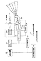
図1は、本発明の第1の実施の形態に係る3次元情報取得装置の適用された3次元形状測定装置1の構成を示す図である。
【0040】
この3次元形状測定装置1は、本発明の第1の実施の形態に係る3次元情報取得装置2と3次元画像生成部3とから構成されている。そして、上記3次元情報取得装置2は、パターンメモリ21、ストロボ22、パターン切り替え部23、撮影部24、画像メモリ25、2次元画像情報生成部26、奥行き算出部27、及び、制御部28より構成されている。
【0041】
ここで、上記パターンメモリ21は、上記パターン記憶手段に相当するもので、被写体(図示せず)に投光する投影パターンのコード系列などを記憶しておくものである。上記ストロボ22は、光を照射するためのものであり、上記パターン切り替え部23は、このストロボ22のストロボ光の強度(光の透過率)を場所によって変調する投影パターンの有無を切り替えるものである。上記撮影部24は、上記撮影手段に相当するものであり、上記被写体からの反射光を集光する集光レンズ241と、この集光レンズ241で集めた光を受光する受光部(撮像素子)242とから構成される。上記画像メモリ25は、上記画像記憶手段に相当するものであり、上記撮影部24で撮影した画像を記憶する。上記2次元画像情報生成部26は、上記パターン構造抽出手段に相当するものであり、上記画像メモリ25に記憶されている画像から2次元画像情報を生成する機能に加えて、上記画像メモリ25に記憶されている画像から撮影されたパターンの構造を推定し、その推定結果を上記画像メモリ25に記憶させる機能も備えている。上記奥行き算出部27は、上記奥行き算出手段に相当するものであり、上記画像メモリ25に記憶されている上記推定結果と上記パターンメモリ21に記憶されている投影パターンとから奥行き値を算出する。そして、上記制御部28は、上記ストロボ22の発光制御、上記パターン切り替え部23の投影パターンの有無の切り替え制御、及び上記受光部242の受光制御、などを行なうものである。
【0042】
なお、上記パターン切り替え部23は、本実施の形態では、透過型の液晶装置により構成しており、上記切り替え制御は、上記制御部28が、上記パターンメモリ21に記憶されている投影パターンに従った像を上記透過型液晶装置に表示する/しない、により行なうようになっている。あるいは、上記パターン切り替え部23は、上記パターンメモリ21に記憶された投影パターンと同様のパターンを構成したフィルムを上記ストロボ22の光路上に機械的に進退させる構造とし、その進退を上記制御部28で制御するようにしても良い。更には、機械的に進退させるのではなく、操作者が人手によりストロボ光路上に進退させるものであっても構わない。この場合には、制御部28は直接パターン切り替え部23を制御しないが、例えば、図示しないインジケータやブザーにより、操作者にそのような進退を指示する、あるいは、逆に、操作者の上記フィルムの進退操作後にその操作終了を当該制御部28に指示するための図示しない操作部の操作を判別するような構成を取ることが好ましい。
【0043】
そして、上記3次元画像生成部3は、上記2次元画像情報生成部26で生成された2次元画像情報と、上記奥行き算出部27で算出された奥行き値とから、3次元画像を生成するものである。
【0044】
次に、このような構成の3次元形状測定装置1の動作について説明する。
予め、上記パターンメモリ21には、投影パターンのコード情報を記憶しておく。そして、まず、上記制御部28は、上記パターンメモリ21より上記パターンコード情報を読み出し、そのパターンコード情報に従ったパターンを上記パターン切り替え部23に表示して、上記ストロボ22を発光させることで、上記パターンコード情報に従ったパターン付きフラッシュ即ち投影パターンを被写体(図示せず)に投光する。このとき、上記被写体からの反射光は、上記集光レンズ241によって集光され、上記受光部242に導かれる。よって、上記制御部28は、上記ストロボ22の発光に同期して上記受光部242を動作させ、この受光部242で得られた画像を上記画像メモリ25に記憶する。
【0045】
次に、制御部28は、上記パターン切り替え部23の上記パターン表示を無くした上で、上記と同様にストロボ22及び受光部242を制御することで、パターン無し且つフラッシュ発光有り撮影を行ない、得られた画像を上記画像メモリ25に記憶する。
【0046】
更に、パターン無し且つフラッシュ無し撮影を行なって、得られた画像を上記画像メモリ25に記憶する。
【0047】
こうして3種類の画像を得た後、上記2次元画像情報生成部26では、上記画像メモリ25に記憶された上記3種類の画像から、撮影されたパーンの構造を表すパターン情報を抽出し、画像メモリ25に書き込む。この抽出方法の詳細については後述する。なお、2次元画像情報生成部26は、上記パターン無しフラッシュ画像を上記画像メモリ25から読み出し、平面的な写真情報(2次元画像情報)をいつでも生成できるようになっている。
【0048】
次に、上記奥行き算出部27において、上記パターンメモリ21に記憶された投影パターンのコード情報と、上記画像メモリ25に書き込まれた上記2次元画像情報生成部26で抽出されたパターン情報とを比較、照合し、投影したパターンと撮影されたパターンとの対応関係を決定する。続いて、反射パターン受光位置と焦点距離の情報とから入射角を算出し、上記投影パターンの射出地点と被写体から反射されたパターンの受光地点との間の距離間隔と光の射出角度の情報とから、三角測量の原理によって奥行き値を算出する。
【0049】
最後に、上記3次元画像生成部3において、上記2次元画像情報生成部26で生成された2次元画像情報と、上記奥行き算出部27で算出された奥行き値とから、3次元画像を生成する。
【0050】
上記投影されるパターンについて、図2を用いて説明する。
図2は、上記パターンメモリ21に記憶されたコード情報に従って被写体に投影されるコード済みのカラーパターン4を示しており、更に、このカラーパターン4の下には、R,G,B成分それぞれの輝度値(階調値)を示してある。なお、この図2の例は縞パターンであるが、格子パターンを用いても構わないことは勿論である。
【0051】
このパターン構造は、R,G,Bの各成分に対して、極大(有彩色)と極小(黒)が交互に配置されており、同図には、パターンの縞を識別するためのコード番号を(1),(2),(3)で表している。ここで、コード番号kが割り当てられている縞のR,G,Bの各成分をそれぞれr[k],g[k],b[k]で表すと、図2の例では、各コード番号のR,G,Bの値を次式のように表現することができる。なお、この値は、R,G,Bをそれぞれ256階調とした場合である。
【0052】
(r[1],g[1],b[1])=(85,170,255)
(r[2],g[2],b[2])=(170,255,85)
(r[3],g[3],b[3])=(255,85,170)
この例は、以下に説明する特徴を持ったコード化パターンになっている。
【0053】
コード番号の並び方を利用して、受光したパターン中の縞を射出時のパターン中の縞に一意的に対応づけることは、従来と同じであるが、本実施の形態では、縞の特徴づけに特長がある。
【0054】
まず、第1の特徴は、同一縞内における異なる成分間の関係、例えば、縞の大小、縞の大きさの比、色相などを用いて縞の特徴づけを行なっているものである。この同一縞内における色による特徴づけは、例えば、以下の関係を用いて縞のコード番号を特定することができるコード化方法である。
【0055】
0≪r[1]≪g[1]≪b[1]
0≪b[2]≪r[2]≪g[2]
0≪g[3]≪b[3]≪r[3]
ここで、記号≪は、ノイズの影響による大小関係の逆転が無いぐらいに右辺が左辺よりも充分大きいということを示している。
【0056】
第2の特徴は、異なる縞間における同一成分の大小関係を用いて縞の特徴づけを行なっているものである。この同一成分の階調(輝度)による特徴づけは、例えば、以下の式の関係を用いて縞のコード番号を特定することができるコード化方法である。
【0057】
0≪r[1]≪r[2]≪r[3]
0≪g[3]≪g[1]≪g[2]
0≪b[2]≪g[3]≪g[1]
これら2つの特徴を一つのパターン中に埋め込んだコード化パターンを用いることが、本実施の形態の特長である。
【0058】
そして、この2重の特徴を埋め込んだコード化パターンを、R,G,Bの3成分を共に反射してくるような白色系や淡色系の被写体に対しては、上記第1の特徴である色による特徴によって、パターン射出時の縞の色(コード番号)を特定し、R,G,Bの1成分または2成分を反射するような濃色系の被写体に対しては、上記第2の特徴である同一成分の階調による特徴によってパターン射出時の縞の色を特定するというふうに使い分ける。
【0059】
なお、R,G,Bの3成分を共に反射してくる白色系や淡色系の被写体に色相などの色による特徴を用いてパターン射出時の縞を特定する方法を採用するメリットは、次のように説明できる。R,G,Bの3成分を色相H、彩度S、明度VからなるHSV空間にマッピングして考える。その変換式として、次の式が知られている。
【0060】
H=arctan{(G−B)/(2R−G−B)}
S={(B−R)2+(R−G)2+(G−B)2}/3
V=R+G+B
仮にR,G,Bの値が、それぞれk倍になったとする。このとき、彩度Sはk2倍、明度Vはk倍になってしまうが、色相Hは不変である。即ち、各成分の輝度値が、局所領域毎にそろって定数倍になる状況を想定すると、色相の判定方法は、その影響を受けないが、輝度の階調による判定方法は、影響が大きい。なお、HSV空間でなく、均等色空間(HCV)に変換してもほぼ同様のことが言える。
【0061】
ところで、縞にコード番号を割り当てた場合に、各縞を縞の並びに対して一意的に特定するために、本実施の形態では、最低階調レベル(最小輝度レベル)である黒縞を挟んで隣り合う有彩色縞のコード番号の並びが、一意的となるようなコード系列(コードの並び)を生成する。
【0062】
例えば、3色の色数(コードの種類)を用いた場合に、黒縞を挟んで隣り合う有彩色縞の(同色を許した)組み合わせを考えると、(1)(2)(2)(3)(1)(3)(3)(2)(1)というコード系列ができる。更に長いコード系列が必要ならば、色数を4乃至5色に増やす、または、2本の縞の組み合わせでなく、3乃至4本の縞の色(コード番号)の組み合わせが一意的となるようなコード系列を採用すればよい。
【0063】
このような2重の特徴を埋め込んだコード化パターンは、従来から知られている縞と縞の間の検出法にも利用することができることは勿論であるが、本実施の形態のような装置と組み合わせる事で、より効果を発揮できるものである。
【0064】
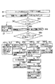
次に、画像処理の流れについて図3を用いて説明する。
まず、コード化済みのカラーパターン4を被写体に投影する(ステップS1)。次に、投影されたパターンを撮影し、その画像データ(Pr,Pg,Pb)を上記画像メモリ25に入力する(ステップS2)。
【0065】
続いて、パターン無しのフラッシュ撮影を行ない、その画像データ(Fr,Fg,Fb)を上記画像メモリ25に入力する(ステップS3)。
【0066】
そして、パターン無しフラッシュ無しの撮影を行ない、その画像データ(Nr,Ng,Nb)を上記画像メモリ25に入力する(ステップS4)。これらステップS1からステップS4までの一連の処理は、一瞬のうちに行なわれ、必要な情報の入力が完了する。
【0067】
この後、上記2次元画像情報生成部26において、上記画像メモリ25に入力した情報からパターンの縞構造を抽出し、各縞に対して当該縞の射出時の色を特定し、デコード処理を実施していくことになるが、それぞれの処理を以下に詳しく説明する。
【0068】
まず、パターン像から、外光や被写体の表面反射率特性の違いによる影響を取り除き、射出時のパターンを推定する処理を施す。ここで、図4を用いて、この処理に必要な関係式を説明する。図4のように、フラッシュの投光強度をL、パターンの透過率をT、被写体の表面反射率をR、外光の強度をSとし、これらを受光した画像の各画素の関数として考える。ここで、上記パターン切り替え部23から射出した光線と上記受光部242に入射する光線が、光の拡散などを無視して1対1の関係で記述できると近似して考えれば、
投影パターン撮影画像の画素強度P=R(TL+S)
フラッシュ撮影画像の画素強度F=R(L+S)
フラッシュ無し撮影画像の画素強度N=RS
と書くことができる。これら3式を連立させてTについて解くと
T=(P−N)/(F−N)
例えば、R,G,Bの3成分に対して画素強度値が得られる場合には、R,G,Bが互いに独立であると近似して考えれば、R,G,Bに対する推定パターン透過率Tr,Tg,Tbは、
Tr=(Pr−Nr)/(Fr−Nr)
Tg=(Pg−Ng)/(Fg−Ng)
Tb=(Pb−Nb)/(Fb−Nb)
という式によって求められる。ただし、ノイズなどの影響に対処するため、分母がゼロに近い場合には、その成分を除いて考える必要がある。
【0069】
ここで図3に戻り、画像処理の流れの説明を再開する。
即ち、ステップS5で、上式の分母、即ち(Fi−Ni)(ここでi=r,g,b)が、予め設定してあるノイズレベル以上であるか否かを判定し、ノイズレベル以上であるならば、その成分の推定パターン透過率Tiを上式を用いて算出する(ステップS6)。これに対して、ノイズレベル未満であれば、その成分の推定パターン透過率を不定とし、以後の処理に影響を与えないような値を入力しておく(ステップS7)。
【0070】
次に、パターンの縞構造(Tiのグラフの極大、極小位置)を検出する(ステップS8)。これには、例えばSobelフィルタなどにより、縞のエッジ部分を抽出し、エッジに挟まれた区間で、Tiの強度が極大となるか、極小となるかを判定する。この縞構造の抽出処理においても投影パターン撮影画像Piでなく、推定パターン透過率Tiを用いているので、外光や被写体の表面反射率特性の違いによる影響を大幅に緩和することができる。
【0071】
続いて、エッジに挟まれた区間に対して、当該縞の射出時の色を特定する処理に移る。
【0072】
即ち、まず、(Fi−Ni)(ここでi=r,g,b)がノイズレベル以上となる成分数を調べる(ステップS9)。
【0073】
ここで、成分数が0であれば、その領域の3次元形状は推定できないことになる(ステップS10)。これは、黒色の被写体の場合である。
【0074】
もし、ノイズレベル以上となる成分数が1であれば、1成分のみ反射する領域において、推定パターン透過率Tiのヒストグラムを作成する(ステップS11)。このヒストグラムに対し、例えば、判別分析の手法により、ヒストグラムをパターン作成時の階調数、例えば本実施の形態では3分割に分割するような閾値を自動的に設定する(ステップS12)。次に、上記ステップS12で設定した閾値を用いて、推定パターン透過率Tiの階調を判定する(ステップS13)。そして、上記判別した推定パターン透過率Tiの階調によって当該縞の射出時の色を特定し、コード番号を推定する(ステップS14)。
【0075】
また、ノイズレベル以上となる成分数が2であれば、その2成分の推定パターン透過率Tiの大きさを比較する(ステップS15)。次に、2成分の推定パターン透過率Tiの和を算出し、2成分を反射する領域における和の値のヒストグラムを作成する(ステップS16)。次に、例えば判別分析の手法により、ヒストグラムを2分割するような閾値を自動的に設定する(ステップS17)。その後、この設定した閾値を用いて、2成分の推定パターン透過率Tiの和の階調を判定する(ステップS18)。そして、2成分の推定パターン透過率Ti間の大小関係及び2成分の推定パターン透過率Tiの和に対する階調値によって、当該縞の射出時の色を特定し、コード番号を推定する(ステップS19)。
【0076】
更に、ノイズレベル以上となる成分数が3であれば、3成分の(255*Ti)の値から色相を算出し(ステップS20)、算出された色相が射出時の色相のどれに最も近いかを判定し、当該縞の射出時の色を特定し、コード番号を推定する(ステップS21)。なお、色相で縞の色を特定する代わりに、例えば、3成分間の比または大小関係を利用してもよい。
【0077】
この手続きを最大視差の区間内の画素に対して行なうことで、コード番号の列が推定され、その推定結果が、この2次元画像情報生成部26で抽出された上記パターン情報として、上記画像メモリ25に書き込まれる。
【0078】
次に、上記奥行き算出部27において、このパターン情報におけるコード番号の列と、上記パターンメモリ21に記憶されているコード系列とを比較、照合する。本実施の形態では、黒縞を挟んで隣り合う有彩色縞の組み合わせが一致しているものを探す。上記推定されたコード番号の列における黒縞を挟んで隣り合う有彩色縞の組み合わせと一致するコード系列が複数ある場合には、例えば、上記推定されたコード番号の列と連続して一致するコード番号との長さが最大のコード系列を信頼性が高いとして選択する。この処理を繰り返すことによって、デコード処理が完了し、投光パターンと受光パターンとの各縞に対して、1対1の対応関係が定まる。最後に、三角測量の原理から被写体の各点での奥行き値が算出される。
【0079】
以上説明したように本実施の形態によれば、濃色系の被写体においても射出時の縞の色を推定可能なパターンを提供しているので、白色系または淡色系だけでなく濃色系の被写体に対してまで3次元形状を取得することができ、被写体の色に関する制約を緩めることができる効果がある。
【0080】
即ち、図9に示したような従来例では、例えば、赤い被写体上に、R成分の強度変化がないパターン領域(GまたはBの強度変化があるパターン領域)が投射された場合に縞と縞の間の変化を検出できず、その部分に対して3次元形状の取得ができないという問題があった。これに対し、本実施の形態によれば、縞と縞の間ではR,G,B全ての成分値が必ず変化しているので、黒以外のどんな被写体にパターンが投影されても、縞と縞の間の変化を必ず検出することができ、3次元形状の取得ができない領域を減らす効果がある。勿論、本実施の形態のようなコード済みのカラーパターン4を用い、従来から知られている縞と縞の間の検出法を適用することによっても、この効果を得ることができるが、本実施の形態のような装置と組み合わせる事で、より効果を発揮できる。
【0081】
また、本実施の形態によれば、蛍光灯または電球など、様々な色の外光の下でも、または、表面反射率特性が異なる種々の被写体に対しても、パターン付きフラッシュ撮影画像、パターン無しフラッシュ撮影画像及びパターン無しフラッシュ無し撮影画像の3種類の画像を用いることによって、パターンの射出時の色をより正確に確定することができ、3次元計測の誤りを少なくできる効果がある。
【0082】
更に、本実施の形態によれば、縞と縞との間ではR,G,B全ての成分値が必ず変化しているので、黒以外のどんな被写体にパターンが投影されても、縞と縞との間の変化を必ず検出することができ、3次元形状の取得ができない領域を減らす効果がある。
【0083】
また、本実施の形態によれば、R,G,B全ての成分値が、極大、極小となる区間または領域を交互に配置しているので、縞と縞との境界で変曲点を許すようなパターン構造に比べて、縞と縞との境界を容易に検出できる効果がある。更に、光の拡散によって縞と縞との境界が消失してしまう危険性を減らす効果もある。
【0084】
[第2の実施の形態]
次に、本発明の第2の実施の形態を説明する。本第2の実施の形態は、方法部分は、上記第1の実施の形態で用いた3次元情報取得方法と同じであるが、装置構成が異なる。
【0085】
即ち、本第2の実施の形態に係る3次元情報取得装置2は、図5に示すように、被写体に投光するパターンを記憶しておくパターンメモリ21、光を照射するためのストロボ22、場所によって光の強度(透過率)を変調するパターンの有無を切り替えるパターン切り替え部23、反射された光を集光する集光レンズ241R及び241L、これら集光レンズ241R及び241Lで集光された光を受光する受光部242R及び5242、撮影された画像を記憶する画像メモリ25R及び25L、これら画像メモリ25R及び25Lに記憶された画像から2次元画像情報を生成する2次元画像情報生成部26、上記画像メモリ25R及び25Lに記憶された画像と上記パターンメモリ21に記憶されたパターンとの対応を決定する対応関係決定部29、該対応関係決定部29で決定された対応関係から三角測量の原理を用いて奥行き値を算出する奥行き算出部27、及び上記ストロボ22、パターン切り替え部23、受光部242R,242Lを制御する制御部28から構成されている。
【0086】
そして、このような3次元情報取得装置2と共に3次元形状測定装置1を構成する3次元画像生成部3は、上記2次元画像情報生成部26に記憶された2次元画像情報と上記奥行き算出部27で算出された奥行き値とから3次元画像を生成するようになっている。
【0087】
次に、このような本第2の実施の形態に係る3次元情報取得装置2の動作について説明する。
【0088】
まず、上記制御部28により上記ストロボ22を発光し、上記パターン切り替え部23で光を変調して被写体(図示せず)にパターンを投影する。この投影像は、2つの異なる位置、例えば上記ストロボ22及びパターン切り替え部23の右と左に配置された集光用レンズ241R及び241Lによって集光される。続いて、集光された光は、それぞれ受光部242R、242Lで受光され、各々、画像メモリ25R、25Lに記憶される。パターン無しフラッシュ撮影画像とパターン無しフラッシュ無し撮影画像についてもそれぞれ同様にして画像メモリ25R、25Lに記憶される。上記第1の実施の形態との違いは、これら3種類の画像が、視点の異なる2個所の画像メモリに書き込まれている点である。
【0089】
そして、上記第1の実施の形態における場合と同様に、上記2次元画像情報生成部26で左右それぞれについて3種類の画像から、射出時の推定パターン情報を算出し、画像メモリ25R及び25Lに書き込む。
【0090】
次に、上記対応関係決定部29において、上記パターンメモリ21に記憶されたパターン情報と上記画像メモリ25Rに書き込んだ右の推定パターン情報、上記パターンメモリ21に記憶されたパターン情報と上記画像メモリ25Lに書き込んだ左の推定パターン情報、上記右の画像メモリ25Rに書き込んだパターン情報と上記左の画像メモリ25Lに書き込んだパターン情報の推定パターン情報、及び上記右の受光部242Rと上記左の受光部242Lとで受光したパターン無しフラッシュ投影画像、の4通りの対応づけが行なわれる。
【0091】
このとき、パッシブステレオ法の場合に問題となるテクスチャの無い領域への対応づけの困難さがかなり軽減されている。
【0092】
更に、上記第1の実施の形態においては、投影したパターンと撮影されたパターンとの対応関係を奥行き値算出の手がかりとしたが、本実施の形態においては、左右のパターン無し画像及びパターン有り画像の対応関係をも利用できるので、より信頼性の高い対応づけを実現できる。
【0093】
以上説明したように本第2の実施の形態によれば、2つ以上の視点に置かれた撮像素子でパターンの投影像を取得し、投影したパターンと撮影されたパターンとの対応づけだけでなく、複数画像間の対応づけも行なうため、より正確な対応づけが可能となり、計測精度と信頼性が向上する効果がある。
【0094】
[第3の実施の形態]
次に、本発明の第3の実施の形態を説明する。
【0095】
本第3の実施の形態の装置構成については、前述の第1の実施の形態あるいは第2の実施の形態のそれと同様である。異なる点は、高速シャッタ(例えば、1/500秒)で撮影することによって外光の影響を抑える点である。これによって、パターン無しフラッシュ無し撮影を省くことが可能になるので、投影パターン撮影とパターン無しフラッシュ撮影との2回で画像の取り込みが完了する。
【0096】
これに伴って、処理の流れが前述の第1の実施の形態等よりも、少し簡素化される。図6を用いて、これを説明する。
【0097】
まず、コード化済みのカラーパターン4を被写体に投影する(ステップS1)。次に、投影されたパターンを撮影し、その画像データ(Pr,Pg,Pb)を上記画像メモリ25に入力する(ステップS2)。
【0098】
続いて、パターン無しのフラッシュ撮影を行ない、その画像データ(Fr,Fg,Fb)を上記画像メモリ25に入力する(ステップS3)。これらステップS1からステップS3までの一連の処理は、一瞬のうちに行なわれ、必要な情報の入力が完了する。
【0099】
この後、上記2次元画像情報生成部26において、上記画像メモリ25に入力した情報からパターンの縞構造を抽出し、各縞に対して当該縞の射出時の色を特定し、デコード処理を実施していくことになるが、それぞれの処理を以下に詳しく説明する。
【0100】
まず、パターン像から、外光や被写体の表面反射率特性の違いによる影響を取り除き、射出時のパターンを推定する処理を施す。ここで、図4を用いて、この処理に必要な関係式を説明する。図4のように、フラッシュの投光強度をL、パターンの透過率をT、被写体の表面反射率をR、外光の強度をSとし、これらを受光した画像の各画素の関数として考える。ここで、上記パターン切り替え部23から射出した光線と上記受光部242に入射する光線が、光の拡散などを無視して1対1の関係で記述できると近似して考えれば、
投影パターン撮影画像の画素強度P=R(TL+S)
フラッシュ撮影画像の画素強度F=R(L+S)
と書くことができる。本第3の実施の形態においては、高速シャッタで撮影するので、Sを近似的に0とみなすことができる。この時、これら2式を連立させTについて解くと
T=P/F
例えば、R,G,Bの3成分に対して画素強度値が得られる場合には、R,G,Bが互いに独立であると近似して考えれば、R,G,Bに対する推定パターン透過率Tr,Tg,Tbは、
Tr=Pr/Fr
Tg=Pg/Fg
Tb=Pb/Fb
という式によって求められる。ただし、ノイズなどの影響に対処するため、分母がゼロに近い場合には、その成分を除いて考える必要がある。
【0101】
そこで図6に戻るが、ステップS31で、上式の分母、即ちFi(ここでi=r,g,b)が、予め設定してあるノイズレベル以上か否かを判定し、そうであれば、その成分の推定パターン透過率Tiを上式を用いて算出する(ステップS32)。これに対して、ノイズレベル未満であれば、その成分の推定パターン透過率を不定とし、以後の処理に影響を与えないような値を入力しておく(ステップS7)。
【0102】
次に、パターンの縞構造(Tiのグラフの極大、極小位置)を検出する(ステップS8)。これには、例えばSobelフィルタなどにより、縞のエッジ部分を抽出し、エッジに挟まれた区間で、Tiの強度が極大となるか、極小となるかを判定する。この縞構造の抽出処理においても投影パターン撮影画像Piでなく、推定パターン透過率Tiを用いているので、外光や被写体の表面反射率特性の違いによる影響を大幅に緩和することができ、縞を安定して抽出することができる。
【0103】
続いて、エッジに挟まれた区間に対して、当該縞の射出時の色を特定する処理に移る。
【0104】
即ち、まず、Fi(ここでi=r,g,b)がノイズレベル以上となる成分数を調べる(ステップS33)。
【0105】
ここで、成分数が0であれば、その領域の3次元形状は推定できないことになる(ステップS10)。これは、黒色の被写体の場合である。
【0106】
もし、ノイズレベル以上となる成分数が1であれば、1成分のみ反射する領域において、推定パターン透過率Tiのヒストグラムを作成する(ステップS11)。このヒストグラムに対し、例えば、判別分析の手法により、ヒストグラムをパターン作成時の階調数に分割するような閾値を自動的に設定する(ステップS12)。次に、上記ステップS12で設定した閾値を用いて、推定パターン透過率Tiの階調を判定する(ステップS13)。そして、上記判別した推定パターン透過率Tiの階調によって当該縞の射出時の色を特定し、コード番号を推定する(ステップS14)。
【0107】
また、ノイズレベル以上となる成分数が2であれば、その2成分の推定パターン透過率Tiの大きさを比較する(ステップS15)。次に、2成分の推定パターン透過率Tiの和を算出し、2成分を反射する領域における和の値のヒストグラムを作成する(ステップS16)。次に、例えば判別分析の手法により、ヒストグラムを2分割するような閾値を自動的に設定する(ステップS17)。その後、この設定した閾値を用いて、2成分の推定パターン透過率Tiの和の階調を判定する(ステップS18)。そして、2成分の推定パターン透過率Ti間の大小関係及び2成分の推定パターン透過率Tiの和に対する階調値によって、当該縞の射出時の色を特定し、コード番号を推定する(ステップS19)。
【0108】
更に、ノイズレベル以上となる成分数が3であれば、3成分の(255*Ti)の値から色相を算出し(ステップS20)、算出された色相が射出時の色相のどれに最も近いかを判定し、当該縞の射出時の色を特定し、コード番号を推定する(ステップS21)。なお、色相で縞の色を特定する代わりに、例えば、3成分間の比または大小関係を利用してもよい。
【0109】
この手続きを最大視差の区間内の画素に対して実施していくことにより、コード番号の列が推定され、その推定結果が、この2次元画像情報生成部26で抽出された上記パターン情報として、上記画像メモリ25に書き込まれる。
【0110】
そして、上記奥行き算出部27での、上記パターン情報におけるコード番号の列と、上記パターンメモリ21に記憶されているコード系列とを照合した後、奥行きを算出するまでの処理は、前述の第1の実施の形態と同じである。
【0111】
[第4の実施の形態]
次に、本発明の第4の実施の形態を説明する。
【0112】
本第4の実施の形態では、装置構成が、前述の第1の実施の形態と少し異なる。
【0113】
即ち、図7に示すように、前述の第1の実施の形態におけるストロボ22及びパターン切り替え部23の代わりに、本第4の実施の形態では、パターン照射用ストロボ22−1と、該パターン照射用ストロボ22−1の前面に配されたフィルム上に設けられた固定のパターン41と、ストロボ22−2とを備えた構成になっている。ここで、前述したような投影パターン撮影の際には上記パターン照射用ストロボ22−1を発光させ、上記パターン無しフラッシュ撮影の際には上記ストロボ22−2を発光させるよう、上記制御部28によって制御されるものである。
【0114】
このような構成の第4の実施の形態では、前述の第1の実施の形態におけるパターン切り替え部223のような可動部がないため、壊れにくい、消費電力が少なくて済む、等のメリットがある。
【0115】
ただし、上記パターン照射用ストロボ22−1による照射条件と上記ストロボ22−2による照射条件とが、ほぼ同一の条件となるようにする必要がある。即ち、発光特性が似たものを互いに近い位置に設置し、フラッシュの照射方向も同じにしておく方が望ましい。
【0116】
尚、処理の流れについては、前述の第1の実施の形態、または、高速シャッタ撮影による上記第3の実施の形態と同様である。
【0117】
[第5の実施の形態]
次に、本発明の第5の実施の形態を説明する。
【0118】
この第5の実施の形態における装置構成については、前述の第1の実施の形態あるいは前述の第2の実施の形態のそれと同様である。異なる点は、高速シャッタで撮影することによって外光の影響を抑える点、及び、例えばリンゴのようにほぼ均一で一様な色をしている被写体を3次元計測の対象物として想定している点である。
【0119】
この場合、パターン無しフラッシュ無し撮影とパターン無しフラッシュ撮影とを省き、投影パターン撮影1回のみで画像の取り込みを完了させる。
【0120】
これに伴って、処理の流れが、前述の第1の実施の形態等よりも、さらに簡素化される。図8を用いて、これを説明する。
【0121】
まず、コード化済みのカラーパターン4を被写体に投影する(ステップS1)。次に、投影されたパターンを撮影し、その画像データ(Pr,Pg,Pb)を上記画像メモリ25に入力する(ステップS2)。
【0122】
この後、上記2次元画像情報生成部26において、上記画像メモリ25に入力した情報からパターンの縞構造を抽出し、各縞に対して当該縞の射出時の色を特定し、デコード処理を実施していくことになるが、それぞれの処理を以下に詳しく説明する。
【0123】
即ち、まず、Pi(ここでi=r,g,b)が、予め設定してあるノイズレベル以上であるか否かを判定し(ステップS51)、ノイズレベル未満であれば、その成分の推定パターン透過率を不定とし、以後の処理に影響を与えないような値を入力しておく(ステップS7)。
【0124】
また、ノイズレベル以上であれば、パターンの縞構造(Piのグラフの極大、極小位置)を検出する(ステップS52)。これには、例えばSobelフィルタなどにより、縞のエッジ部分を抽出し、エッジに挟まれた区間で、Piの強度が極大となるか、極小となるかを判定する。
【0125】
続いて、エッジに挟まれた区間に対して、当該縞の射出時の色を特定する処理に移る。
【0126】
即ち、まず、Pi(ここでi=r,g,b)がノイズレベル以上となる成分数を調べる(ステップS53)。
【0127】
ここで、成分数が0であれば、その領域の3次元形状は推定できないことになる(ステップS10)。これは、黒色の被写体の場合である。
【0128】
もし、ノイズレベル以上となる成分数が1であれば、1成分のみ反射する領域において、推定パターン透過率Piのヒストグラムを作成する(ステップS54)。このヒストグラムに対し、例えば、判別分析の手法により、ヒストグラムをパターン作成時の階調数に分割するような閾値を自動的に設定する(ステップS12)。次に、上記ステップS12で設定した閾値を用いて、推定パターン透過率Piの階調を判定する(ステップS55)。そして、上記判別した推定パターン透過率Piの階調によって当該縞の射出時の色を特定し、コード番号を推定する(ステップS56)。
【0129】
また、ノイズレベル以上となる成分数が2であれば、その2成分の推定パターン透過率Piの大きさを比較する(ステップS57)。次に、2成分の推定パターン透過率Piの和を算出し、2成分を反射する領域における和の値のヒストグラムを作成する(ステップS58)。次に、例えば判別分析の手法により、ヒストグラムを2分割するような閾値を自動的に設定する(ステップS17)。その後、この設定した閾値を用いて、2成分の推定パターン透過率Piの和の階調を判定する(ステップS59)。そして、2成分の推定パターン透過率Pi間の大小関係及び2成分の推定パターン透過率Piの和に対する階調値によって、当該縞の射出時の色を特定し、コード番号を推定する(ステップS60)。
【0130】
更に、ノイズレベル以上となる成分数が3であれば、3成分のPiの値から色相を算出し(ステップS61)、算出された色相が射出時の色相のどれに最も近いかを判定し、当該縞の射出時の色を特定し、コード番号を推定する(ステップS21)。なお、色相で縞の色を特定する代わりに、例えば、3成分間の比または大小関係を利用してもよい。
【0131】
この手続きを最大視差の区間内の画素に対して実施していくことにより、コード番号の列が推定され、その推定結果が、この2次元画像情報生成部26で抽出された上記パターン情報として、上記画像メモリ25に書き込まれる。
【0132】
そしてその後の、上記奥行き算出部27における、このパターン情報におけるコード番号の列と、上記パターンメモリ21に記憶されているコード系列とを照合した後、奥行きを算出するまでの処理は、前述の第1実施の形態と同じである。
【0133】
以上、実施の形態に基づいて本発明を説明したが、本発明は上述した実施の形態に限定されるものではなく、本発明の要旨の範囲内で種々の変形や応用が可能である。
【0134】
ここで、本発明の要旨をまとめると特許請求の範囲に記載したものに加えて以下のようなものを含む。
【0135】
(1) カラーパターンを投影し、この投影像をR,G,B信号のように複数の独立な周波数成分に分けて受光する素子を有する3次元画像取得装置において、
該カラーパターンは、
全信号成分の組み合わせである色によるコード化と、
階調によるコード化と、
が同時に一つのパターン中に備わっていることを特徴とする3次元情報取得装置。
【0136】
(2) 予めコード化済みのパターンをフラッシュ(ストロボ)やプロジェクタなどの照明手段を発光させて被写体に向けて投影し、この投影像をカメラで撮影して得られるパターン付きフラッシュ撮影画像と、
パターン無しでフラッシュ撮影して得られるフラッシュ撮影画像と、
パターン無しフラッシュ無しで撮影して得られるフラッシュ無し撮影画像と、の3タイプの画像を取得し、これら3種類の画像からパターンの縞構造の抽出及び縞のデコードを行なうことを特徴とする3次元情報取得装置。
【0137】
(3) 上記3次元情報取得装置は、予めコード化済みのパターンをフラッシュ(ストロボ)やプロジェクタなどの照明手段を発光させて被写体に向けて投影し、この投影像をカメラで撮影して得られるパターン付きフラッシュ撮影画像と、
パターン無しでフラッシュ撮影して得られるフラッシュ撮影画像と、
パターン無しフラッシュ無しで撮影して得られるフラッシュ無し撮影画像と、の3タイプの画像を取得し、これら3種類の画像からパターンの縞構造の抽出及び縞のデコードを行なうことを特徴とする(1)に記載の3次元情報取得装置。
【0138】
(4) 上記3次元情報取得装置は、
カラーコード化パターンの有無を切り替えるパターン切り替え部と、
上記パターンを投射するための光投射部と、
上記カラーパターンのコードを記憶するパターンメモリと、
被写体から反射された光を受光する受光部と、
上記画像メモリに記憶されたパターンと上記パターンメモリで記憶されたパターンとから被写体の奥行き情報を算出する奥行き算出部と、
上記受光部で受光された情報を記憶する画像メモリと、
上記画像メモリから2次元画像情報を生成する2次元画像情報生成部と、
上記2次元画像情報生成部で生成された2次元画像情報と上記奥行き算出部で算出された奥行き値とから3次元画像を生成する3次元画像生成部と、
を有することを特徴とする(1)に記載の3次元情報取得装置。
【0139】
(5) 上記3次元情報取得装置は、
上記受光部と上記画像メモリとをそれぞれ複数具備し、
これら複数の画像メモリ同士の内容をマッチングし、画像間の対応づけを行なう対応関係決定部と、
上記対応関係決定部で決定された情報を基に上記奥行き算出部で被写体の奥行き値を算出し、上記2次元画像情報生成部で生成された2次元画像情報と上記奥行き算出部で算出された奥行き値とから3次元画像を生成する3次元画像生成部と、
を更に具備することを特徴とする(4)に記載の3次元情報取得装置。
【0140】
(6) カラーパターンを投影し、この投影像をR,G,B信号のように複数の独立な周波数成分に分けて受光し、上記受光した信号をデコードすることで3次元情報を取得する3次元画像取得方法において、
該カラーパターンは、
全ての信号成分値の組み合わせである色によるコード化と、
階調によるコード化と、
が同時に一つのパターン中に備わっていることを特徴とする3次元情報取得方法。
【0141】
(7) 上記3次元情報取得方法は、縞パターンまたは格子パターンのような縞状のパターンであって、縞と縞の間では、上記全ての信号成分値が必ず変化していることを特徴とする(6)に記載の3次元情報取得方法。
【0142】
(8) 上記3次元情報取得方法は、上記全ての信号成分値が、極大または極小となる区間もしくは領域を交互に配置したことを特徴とする(6)に記載の3次元情報取得方法。
【0143】
(9) 上記3次元情報取得方法は、2本以上の色の組み合わせから一意的に縞が特定されることを特徴とする(6)に記載の3次元情報取得方法。
【0144】
(10) 上記3次元情報取得方法は、フラッシュ撮影画像及びフラッシュ無し撮影画像を用いて、利用可能な反射光の成分を判定し、全ての成分が利用可能ならば、色によってコード番号を特定し、全ての成分ではないが一つ以上の成分が利用可能ならば、各成分の階調によってコード番号を特定することを特徴とする(6)に記載の3次元情報取得方法。
【0145】
(11) 上記投影パターンにおける各色成分のパターンは、隣り合う領域が互いに階調(輝度)が異なるように複数の領域が配置されたものであることを特徴とする請求項26乃至28の何れかに記載の3次元情報取得方法。
【0146】
(12) 上記投影パターンにおける各色成分のパターンは、階調(輝度)が極大となる領域と極小となる領域を交互に配置されたものであることを特徴とする請求項26乃至28の何れかに記載の3次元情報取得方法。
【0147】
(13) 上記階調(輝度)が極小となる領域は、最低階調(最小輝度)レベルであることを特徴とする(12)に記載の3次元情報取得方法。
【0148】
(14) 上記投影パターンは、異なる有彩色に着色された複数の領域を含み、
上記投影パターン中の有彩色の領域は、上記各色成分のパターンの所定の階調(輝度)を有する領域の組み合わせで構成されたものであると共に、一つの色成分のパターンにおける任意の上記領域の階調(輝度)は、他の色成分のパターンにおける上記任意の領域の階調と互いに異なり、これによって上記任意の領域が上記投影パターンの中のどの領域であるかの対応が特定できるように、上記投影パターンが符号化されている、
ことを特徴とする請求項26乃至28の何れかに記載の3次元情報取得方法。
【0149】
(15) 上記複数の色成分は、R,G,Bの3成分であることを特徴とする請求項26乃至28の何れかに記載の3次元情報取得方法。
【0150】
(16) 上記パターン構造の推定は、上記撮影されたパターンの色により上記撮影されたパターンの構造を推定する第1の推定方法と、全ての色成分でない一つ以上の色成分の階調(輝度)により上記撮影されたパターンの構造を推定する第2の推定方法とを選択的に実行することで行なわれ、
上記第1または第2の推定方法による推定結果が以降の処理に利用されることを特徴とする請求項26又は27に記載の3次元情報取得方法。
【0151】
【発明の効果】
以上詳述したように、本発明によれば、白色系や淡色系物体測定用である色による特徴と濃色系物体測定用である同一色成分の階調による特徴という2つの異なる特徴を併せ持つ投影パターンを用い、投影パターン撮影画像とフラッシュ撮影画像とフラッシュ無し撮影画像との3種類の画像から、反射率、外光補正を行なって、パターン特定を行なった上で、奥行き値を算出するようにしているので、淡色系物体だけでなく濃色系物体においても3次元情報を取得することができる3次元情報取得装置、3次元情報取得における投影パターン、及び、3次元情報取得方法を提供することができる。
【0152】
また、本発明によれば、色(成分値の組み合わせ)による縞の特徴づけと同一成分の階調による特徴づけとを一つのパターン中に同時に埋め込んだコード化を行ない、白色系や淡色系の物体については、色による特徴によって、濃色系の物体についてはノイズレベル未満の反射成分値の階調による特徴によってデコードしているので、濃色系も含めた様々な色の物体に対して投光パターン中の位置と受光パターン中の位置を確実に対応づけることが可能な3次元情報取得装置、3次元情報取得における投影パターン、及び、3次元情報取得方法を提供することができる。その結果、様々な色の物体に対して3次元形状の測定をより正確に行なえる効果がある。
【図面の簡単な説明】
【図1】本発明の第1の実施の形態に係る3次元情報取得装置の適用された3次元形状測定装置のブロック構成図である。
【図2】第1の実施の形態において被写体に投影されるパターンの例を示す図である。
【図3】第1の実施の形態における画像処理の射出時の色を特定するまでの流れを説明するためのフローチャートを示す図である。
【図4】第1の実施の形態における撮影時の種々のパラメータについて説明するための図である。
【図5】本発明の第2の実施の形態に係る3次元情報取得装置の適用された3次元形状測定装置のブロック構成図である。
【図6】本発明の第3の実施の形態における画像処理の射出時の色を特定するまでの流れを説明するためのフローチャートを示す図である。
【図7】本発明の第4の実施の形態に係る3次元情報取得装置の適用された3次元形状測定装置のブロック構成図である。
【図8】本発明の第5の実施の形態における画像処理の射出時の色を特定するまでの流れを説明するためのフローチャートを示す図である。
【図9】従来の技術によるパターンの例を示す図である。
【図10】従来の技術によるカラーパターン投影法の処理の流れを説明するためのフローチャートを示す図である。
【符号の説明】
1 3次元形状測定装置
2 3次元情報取得装置
3 3次元画像生成部
4 カラーパターン
21 パターンメモリ
22,22−2 ストロボ
22−1 パターン照射用ストロボ
23 パターン切り替え部
24,24R,24L 撮影部
25,25R,25L 画像メモリ
26 2次元画像情報生成部
27 奥行き算出部
28 制御部
29 対応関係決定部
241,241R,241L 集光レンズ
242,242R,242L 受光部[0001]
BACKGROUND OF THE INVENTION
The present invention relates to a three-dimensional information acquisition apparatus capable of acquiring a depth value by projecting a pattern onto a subject and obtaining a correspondence between a light receiving pattern and a light projection pattern in order to measure a three-dimensional shape. The present invention relates to a projection pattern in three-dimensional information acquisition and a three-dimensional information acquisition method.
[0002]
[Prior art]
Conventional three-dimensional object shape measurement methods are roughly classified into the following two types. One is a method by measuring the propagation time of light, and the other is a method using the principle of triangulation. The former has no blind spot and is an ideal method in principle. However, at present, since the measurement time and accuracy are problematic, the latter triangulation method is mainly used.
[0003]
Methods using this triangulation include an active method that is an active method and a passive stereo method that is a passive method.
[0004]
The passive stereo method associates stereo images obtained from two cameras with different positions, and triangulation is performed based on the result of the correspondence and the positional relationship between the two cameras measured in advance. This is a method for obtaining the distance to the subject based on the principle. This method has the disadvantages that it is difficult to associate images and that the shape of an object having no texture cannot be obtained.
[0005]
On the other hand, as an active method using the principle of triangulation, one of the two cameras is replaced with a light source, and the image of the light source on the object surface is observed with a camera set as the other viewpoint to measure the shape. There is a light projection method. This light projection method can be further classified into a spot light projection method, a slit light projection method, and a pattern light projection method.
[0006]
In the spot light projection method, only one point of the subject can be measured with one image input.
[0007]
In the slit light projection method, one line of an object can be measured with a single image input. However, in order to measure the shape of the entire subject, the image is input many times while deflecting the projection light. Need to be repeated and input takes time.
[0008]
The pattern light projection method projects a two-dimensional pattern such as a fringe pattern or a lattice pattern onto a subject, and can be measured in a short time because the number of pattern projection image inputs may be reduced. There are benefits.
[0009]
This pattern light projection method is also called spatial coding, which is further divided into pattern shape coding and gradation coding.
[0010]
The former pattern shape coding has been proposed to be based on the distribution of the slit opening width and the one using the M-sequence code. However, there are problems in measurement density and measurement stability, and the practicality is poor. It is said.
[0011]
On the other hand, the latter tone coding includes a gray scale and a color.
[0012]
First, with regard to coding by shading, a time-series space coding method using a binary pattern in which a pattern is projected by changing the light / dark pitch twice is well known. This method has excellent features such as being able to suppress coding errors due to misalignment and noise to ± 1, and in order to obtain the same resolution as N slit lights, log 2 N binary patterns may be projected. For example, the same resolution as 128 slit images can be realized by projecting seven binary patterns.
[0013]
However, time-series coding using a binary pattern cannot sufficiently cope with shooting with a hand without being fixed to a tripod or a subject that cannot be stopped still, such as a human being or an animal. This is because if the number of projections is large, shooting cannot be completed within a time period that allows camera shake and subject shake. Furthermore, there are restrictions on the flash charging time and the amount of light emission, and the number of projections that can satisfy these requirements is not sufficient.
[0014]
Therefore, in order to reduce the number of pattern projections, it is conceivable to change the binary pattern to a multi-value pattern. This is proposed in, for example, (Journal of Precision Engineering vol. 62, No. 6, pp. 830-834, 1996). In this case, the luminance difference between each pixel of the flash photographed image and the non-flash photographed image is divided by the number of gradations, and the multi-gradation is determined by which section the luminance value at the time of creation falls.
[0015]
For this reason, when the acquired image has non-linearity such as a gamma characteristic or when there is a small difference in reflected luminance, a decoding error is likely to occur, and stable measurement under normal illumination is difficult. In addition, the measurement results were affected by the state of the object surface such as color. In order to solve these problems, proposals such as a reference projection have been made in the above-mentioned document, but this is not practical because the number of projections increases. As described above, encoding with multiple gradations of luminance is easily affected by variations in luminance, and it has been difficult to set an appropriate threshold value.
[0016]
On the other hand, coding by color has been proposed in, for example, (Journal of the Institute of Electronics, Information and Communication Engineers vol. J61-D, No. 6, pp. 411-418, 1978). FIG. 9 is an example of a fringe pattern coded by R, G, and B colors. By providing a black region having the minimum luminance level between R, G, and B, it is devised so that color mixing due to light diffusion can be reduced.
[0017]
The flow of processing in the conventional color pattern projection method using colors will be described with reference to FIG.
[0018]
First, a coded color pattern as shown in FIG. 9 is projected onto a subject (step S101), and image data (Pr, Pg, Pb) obtained by photographing the projection pattern is obtained (step S102).
[0019]
Subsequently, a stripe structure (maximum position and minimum position of Pr, Pg, and Pb) is detected from the image data (step S103). Then, for each stripe, the color at the time of emission of the stripe is specified by the maximum component among Pr, Pg, and Pb (step S104).
[0020]
Next, the code sequence (color arrangement) of the received stripes is written (step S105), and each code number of the received code sequence and the code number of the code sequence at the time of pattern injection, including the arrangement relationship in the code sequence, are included. Are matched (step S106). As a result, the emission position of the pattern can be uniquely associated with the light reception position of the reflected light, and the depth value is calculated by applying the principle of triangulation to this (step S107).
[0021]
Then, a 3D image is generated from the obtained depth value and the captured 2D image information (step S108).
[0022]
The conventional color pattern projection method performs the above processing.
[0023]
[Problems to be solved by the invention]
However, in the conventional color pattern projection method using colors, it is difficult to measure a three-dimensional shape especially for dark-colored objects. This will be described with reference to FIG.
[0024]
For example, for an object having a surface reflectance characteristic such that the reflected signal of the G component and the B component is almost zero and the reflected signal of the R component is strong (that is, a dark red object such as an apple), R Although one maximum signal is obtained in the luminance values of the components, the luminance values of the G component and the B component almost become noise levels. Under such circumstances, the stripe structure of the G component and the B component cannot be extracted, and moreover, the stripe cannot be specified. That is, even one component of R, G, and B is difficult to decode for an object having a surface reflectance characteristic whose reflected signal is close to zero. In other words, for a white or light-colored object surface, it is possible to decode well, but even one of the reflected signals of the R, G, B components has a surface reflection that gives a noise level value close to zero. For an object having rate characteristics, determination by color, which is obtained from a combination of R, G, and B, becomes difficult.
[0025]
Here, the example of the stripe pattern has been described, but the same applies to the case of a lattice pattern or the like.
[0026]
The present invention has been made in view of the above circumstances, and enables correct decoding from a projected image of a coded pattern not only for white and light-colored objects but also for dark-colored objects. It is an object to provide a three-dimensional information acquisition apparatus, a projection pattern in three-dimensional information acquisition, and a three-dimensional information acquisition method.
[0027]
[Means for Solving the Problems]
In order to achieve the above object, the three-dimensional information acquisition apparatus according to the present invention is configured to capture an imaging target on which a predetermined projection pattern in which a plurality of color component patterns are superimposed from a position away from the imaging unit by a predetermined distance. A three-dimensional information acquisition device that acquires three-dimensional information of the subject to be photographed by photographing with the photographing means and analyzing an image photographed with the photographing means, wherein the photographing is illuminated by light from a light source The same as the first image obtained by photographing the object, the second image obtained by photographing the photographing object without turning off or shielding the light source and illuminating with the light from the light source, and the light from the light source or the light source Image storage means for storing a third image obtained by photographing the photographing object on which the projection pattern is projected using light from another light source having characteristics; and the projection projected on the photographing object. Pattern storage means for storing a pattern in advance, and correction of the surface reflectance of the object to be photographed and the influence of external light using the first, second and third images stored in the image storage means, Pattern structure estimation means for estimating the structure of a photographed pattern based on the color or gradation (luminance) of each part of the pattern obtained by correction, the result of the estimation by the pattern structure estimation means, and the pattern storage means And a depth calculation unit that specifies a correspondence relationship with the projection pattern stored in the image and calculates a depth value of the imaging target based on the identification result of the correspondence relationship.
[0028]
In the three-dimensional information acquisition method according to the present invention, a photographing target on which a predetermined projection pattern in which a plurality of color component patterns are superimposed is projected from a position away from a photographing unit by a predetermined distance is photographed by the photographing means. A three-dimensional information acquisition method for acquiring three-dimensional information of the photographing object by analyzing an image photographed by the photographing means, wherein the photographing object illuminated by light from a light source is photographed first. The first image is obtained, and the light source is turned off or shielded, and the second object is obtained by photographing the subject without illuminating with the light from the light source, and the same as the light from the light source or the light source. A third image is obtained by photographing the photographing object on which the projection pattern is projected using light from another light source having characteristics, and the first, second, and third images are used. Above shooting vs. The surface reflectance of the image and the influence of external light are corrected, and the structure of the photographed pattern is estimated based on the color or gradation (luminance) of each part of the pattern obtained by performing the correction. A correspondence relationship with the projected predetermined projection pattern is specified, and the depth value of the photographing target is calculated based on the result of specifying the correspondence relationship.
[0029]
That is, according to the three-dimensional information acquisition apparatus and the three-dimensional information acquisition method of the present invention, the feature based on the color for measuring the white or light color object and the feature based on the gradation of the same color component for measuring the dark color object. Using the projection pattern having two different features, the first image (light source turned on), the second image (light source turned off), and the third image (pattern projection) Since the depth value is calculated after the influence is corrected and the pattern is specified, three-dimensional information can be acquired not only for the light-colored object but also for the dark-colored object.
[0030]
In order to achieve the above object, the three-dimensional information acquisition apparatus according to the present invention captures a predetermined projection pattern in which a plurality of color component patterns are superimposed from a position away from a capturing unit by a predetermined distance. A three-dimensional information acquisition device that acquires a three-dimensional information of the object to be imaged by capturing the object with the image capturing unit and analyzing the image captured with the image capturing unit, and is illuminated by light from a light source A second image obtained by photographing the photographing object on which the projection pattern is projected using the first image obtained by photographing the photographing object and the light from the light source or the other light source having the same characteristics as the light source. Image storage means for storing the image of the image, pattern storage means for storing the projection pattern projected onto the photographing object in advance, and the first and second images stored in the image storage means. The pattern structure estimation means for correcting the influence of the surface reflectance of the object to be imaged and estimating the structure of the imaged pattern based on the color or gradation (luminance) of each part of the pattern obtained by performing the correction And a correspondence relationship between the result of the estimation by the pattern structure estimation unit and the projection pattern stored in the pattern storage unit, and a depth value of the subject to be photographed is calculated using the identification result of the correspondence relationship And a depth calculating means.
[0031]
In the three-dimensional information acquisition method according to the present invention, a photographing target on which a predetermined projection pattern in which a plurality of color component patterns are superimposed is projected from a position away from a photographing unit by a predetermined distance is photographed by the photographing means. A three-dimensional information acquisition method for acquiring three-dimensional information of the photographing object by analyzing an image photographed by the photographing means, wherein the photographing object illuminated by light from a light source is photographed first. The first image is obtained, and the second image is obtained by photographing the photographing object onto which the projection pattern is projected using light from the light source or light from another light source having the same characteristics as the light source. The first and second images were used to correct the influence of the surface reflectance of the object to be imaged, and the image was captured based on the color or gradation (luminance) of each part of the pattern obtained by performing the correction. pattern A structure is estimated, a correspondence relationship between the estimation result and the projected predetermined projection pattern is specified, and a depth value of the photographing target is calculated using the correspondence relationship specification result It is.
[0032]
That is, according to the three-dimensional information acquisition apparatus and the three-dimensional information acquisition method of the present invention, the feature based on the color for measuring the white or light color object and the feature based on the gradation of the same color component for measuring the dark color object. Using the projection pattern that has the two different features, the surface reflectance of the object to be photographed and the influence of external light are corrected from the first image (light source lighting, high-speed shutter) and the second image (pattern projection, high-speed shutter). Since the depth value is calculated after the pattern is specified, three-dimensional information can be acquired not only for the light-colored object but also for the dark-colored object.
[0033]
Furthermore, in order to achieve the above object, the three-dimensional information acquisition apparatus according to the present invention captures a predetermined projection pattern in which a plurality of color component patterns are superimposed from a position away from a photographing unit by a predetermined distance. A three-dimensional information acquisition apparatus for acquiring three-dimensional information of the photographing target by photographing a target with the photographing means and analyzing an image photographed with the photographing means, wherein the projection pattern is projected An image storage means for storing an image obtained by photographing an object to be photographed, a pattern storage means for preliminarily storing the projection pattern projected onto the photographing object, and a structure of a pattern photographed by the color of the pattern included in the image A first estimation method for estimating, and a second estimation method for estimating the structure of the photographed pattern based on the gradation (luminance) of one or more color components that are not all color components. A pattern structure estimation means that is selectively executed, and a correspondence relationship between the estimation result of the first or second estimation method by the pattern structure estimation means and the projection pattern stored in the pattern storage means, and And a depth calculation means for calculating the depth value of the object to be photographed using the identification result of the correspondence relationship.
[0034]
In the three-dimensional information acquisition method according to the present invention, a photographing target on which a predetermined projection pattern in which a plurality of color component patterns are superimposed is projected from a position away from a photographing unit by a predetermined distance is photographed by the photographing means. A three-dimensional information acquisition method for acquiring three-dimensional information of the photographing object by analyzing an image photographed by the photographing means, wherein the image is obtained by photographing the photographing object on which the projection pattern is projected. A first estimation method for estimating a pattern structure captured by the color of a pattern included in the image, and the pattern captured by the gradation (luminance) of one or more color components that are not all color components A second estimation method for estimating the structure of the first estimation method is selectively executed, a correspondence relationship between the estimation result obtained by the first or second estimation method and the projected predetermined projection pattern is identified, and the pair By utilizing the specific results of the relationship is characterized in calculating the depth value of the imaging target.
[0035]
That is, according to the three-dimensional information acquisition apparatus and the three-dimensional information acquisition method of the present invention, the feature based on the color for measuring the white or light color object and the feature based on the gradation of the same color component for measuring the dark color object. By using a projection pattern having two different features and using a first estimation method for estimating a pattern structure with colors (R, G, B) on which color components are superimposed, a light-colored object is dealt with. By selectively executing the second estimation method for estimating the pattern structure for each component (R only, G only, and B only), it is possible to deal with the dark color object, so that the light color object, dark color Three-dimensional information can be acquired for any system object.
[0036]
In order to achieve the above object, the projection pattern in the acquisition of the three-dimensional information according to the present invention is a projection pattern for analyzing the image obtained by photographing the photographing object and obtaining the three-dimensional information of the photographing object. A plurality of color component patterns superimposed on each other, including a plurality of regions colored in different chromatic colors, wherein the chromatic color region is a predetermined pattern of each color component pattern. It is composed of a combination of areas having gradation (luminance), and the gradation (luminance) of an arbitrary area in one color component pattern is the same as that of the arbitrary area in another color component pattern. The projection pattern is encoded so that it is different from the gradation, and by this, it is possible to specify the correspondence of the arbitrary region to which of the projection pattern. It is an feature.
[0037]
That is, according to the projection pattern in the acquisition of three-dimensional information according to the present invention, there are two different features: a feature by color for measuring white or light-colored objects and a feature by gradation of the same color component for measuring dark-colored objects. Since it also has features, it is possible to acquire three-dimensional information not only for light-colored objects but also for dark-colored objects by using the projection pattern.
[0038]
DETAILED DESCRIPTION OF THE INVENTION
Hereinafter, embodiments of the present invention will be described with reference to the drawings.
[0039]
[First Embodiment]
FIG. 1 is a diagram showing a configuration of a three-dimensional
[0040]
The three-dimensional
[0041]
Here, the
[0042]
In the present embodiment, the
[0043]
The 3D
[0044]
Next, the operation of the three-dimensional
The
[0045]
Next, the
[0046]
Further, photographing without pattern and without flash is performed, and the obtained image is stored in the
[0047]
After obtaining the three types of images in this way, the two-dimensional image
[0048]
Next, the
[0049]
Finally, the 3D
[0050]
The projected pattern will be described with reference to FIG.
FIG. 2 shows a
[0051]
In this pattern structure, the maximum (chromatic color) and the minimum (black) are alternately arranged for each of the R, G, and B components. In the figure, code numbers for identifying the stripes of the pattern are shown. Are represented by (1), (2), and (3). Here, when the R, G, and B components of the stripe to which the code number k is assigned are represented by r [k], g [k], and b [k], respectively, in the example of FIG. The values of R, G, and B can be expressed as follows: This value is obtained when R, G, and B have 256 gradations.
[0052]
(R [1], g [1], b [1]) = (85, 170, 255)
(R [2], g [2], b [2]) = (170, 255, 85)
(R [3], g [3], b [3]) = (255, 85, 170)
This example is a coding pattern having the characteristics described below.
[0053]
Using the arrangement of code numbers to uniquely associate the stripes in the received pattern with the stripes in the pattern at the time of emission is the same as in the past, but in this embodiment, the stripes are characterized. There are features.
[0054]
First, the first feature is to characterize a stripe using a relationship between different components in the same stripe, for example, the size of the stripe, the ratio of the size of the stripe, the hue, and the like. The characterization by color within the same stripe is, for example, a coding method that can specify the code number of the stripe using the following relationship.
[0055]
0 << r [1] << g [1] << b [1]
0 << b [2] << r [2] << g [2]
0 << g [3] << b [3] << r [3]
Here, the symbol << indicates that the right side is sufficiently larger than the left side so that there is no reversal of the magnitude relationship due to the influence of noise.
[0056]
The second feature is to characterize the stripes using the same magnitude relationship between different stripes. The characterization of the same component by gradation (luminance) is, for example, a coding method that can specify the code number of the stripe using the relationship of the following formula.
[0057]
0 << r [1] << r [2] << r [3]
0 << g [3] << g [1] << g [2]
0 << b [2] << g [3] << g [1]
The use of a coding pattern in which these two features are embedded in one pattern is a feature of the present embodiment.
[0058]
The coding pattern in which the double feature is embedded is the first feature for a white or light subject that reflects the three components R, G, and B together. The color of the stripe (code number) at the time of pattern emission is specified according to the characteristics of the color, and for the dark color subject that reflects one component or two components of R, G, B, the second The color of the stripe at the time of pattern emission is specified according to the characteristic of the same component, which is the characteristic, and so on.
[0059]
The merit of adopting a method of specifying a stripe at the time of pattern emission using a color feature such as hue for a white or light subject that reflects the three components of R, G, and B is as follows. Can be explained as follows. The three components R, G, and B are considered by mapping them into an HSV space consisting of hue H, saturation S, and brightness V. As the conversion formula, the following formula is known.
[0060]
H = arctan {(GB) / (2R-GB)}
S = {(BR) 2 + (RG) 2 + (GB) 2 } / 3
V = R + G + B
Suppose that the values of R, G, and B are each multiplied by k. At this time, the saturation S is k 2 Double and lightness V become k times, but hue H remains unchanged. That is, assuming a situation where the luminance values of the respective components are a constant multiple for each local region, the hue determination method is not affected by this, but the luminance gradation determination method has a great influence. The same can be said even if the color space is converted to a uniform color space (HCV) instead of the HSV space.
[0061]
By the way, when code numbers are assigned to the stripes, in order to uniquely identify each stripe with respect to the arrangement of the stripes, in the present embodiment, a black stripe having the lowest gradation level (minimum luminance level) is sandwiched. A code sequence (code sequence) is generated such that the sequence of code numbers of adjacent chromatic color stripes is unique.
[0062]
For example, when the number of colors of three colors (code types) is used, when considering a combination of chromatic stripes adjacent to each other with black stripes (same color allowed), (1) (2) (2) ( 3) A code sequence of (1) (3) (3) (2) (1) is generated. If a longer code sequence is required, the number of colors is increased to 4 to 5 colors, or the combination of 3 to 4 stripe colors (code numbers) is unique rather than the combination of 2 stripes. A simple code sequence may be adopted.
[0063]
Such a coding pattern in which a double feature is embedded can be used for a conventionally known detection method between fringes, as well as an apparatus like this embodiment. By combining with, it can be more effective.
[0064]
Next, the flow of image processing will be described with reference to FIG.
First, the coded
[0065]
Subsequently, flash photography without a pattern is performed, and the image data (Fr, Fg, Fb) is input to the image memory 25 (step S3).
[0066]
Then, photographing without pattern flash is performed, and the image data (Nr, Ng, Nb) is input to the image memory 25 (step S4). A series of processing from step S1 to step S4 is performed in an instant, and input of necessary information is completed.
[0067]
Thereafter, the two-dimensional image
[0068]
First, the pattern image is subjected to a process for estimating the pattern at the time of emission by removing the influence of the difference in external light and the surface reflectance characteristics of the subject. Here, a relational expression necessary for this processing will be described with reference to FIG. As shown in FIG. 4, assume that the projection intensity of the flash is L, the transmittance of the pattern is T, the surface reflectance of the subject is R, and the intensity of the external light is S, and these are considered as functions of each pixel of the received image. Here, if it is approximated that the light beam emitted from the
Pixel intensity P = R (TL + S) of projected pattern captured image
Pixel intensity F of the flash image F = R (L + S)
Pixel intensity N = RS of the image without flash
Can be written. Solving these three equations and solving for T
T = (P−N) / (F−N)
For example, when pixel intensity values are obtained for three components of R, G, and B, the estimated pattern transmittance for R, G, and B can be considered by approximating that R, G, and B are independent of each other. Tr, Tg, Tb are
Tr = (Pr−Nr) / (Fr−Nr)
Tg = (Pg−Ng) / (Fg−Ng)
Tb = (Pb−Nb) / (Fb−Nb)
It is calculated by the formula. However, in order to deal with the effects of noise and the like, when the denominator is close to zero, it is necessary to consider that component.
[0069]
Returning to FIG. 3, the description of the flow of image processing is resumed.
That is, in step S5, it is determined whether or not the denominator of the above equation, that is, (Fi-Ni) (where i = r, g, b) is equal to or higher than a preset noise level. If so, the estimated pattern transmittance Ti of the component is calculated using the above equation (step S6). On the other hand, if it is less than the noise level, the estimated pattern transmittance of the component is made indefinite and a value that does not affect the subsequent processing is input (step S7).
[0070]
Next, the stripe structure of the pattern (maximum and minimum positions of the Ti graph) is detected (step S8). For this purpose, for example, an edge portion of a stripe is extracted by a Sobel filter or the like, and it is determined whether the intensity of Ti is maximized or minimized in a section sandwiched between the edges. Also in this fringe structure extraction processing, the estimated pattern transmittance Ti is used instead of the projection pattern photographed image Pi, so that the influence due to the difference in the external light and the surface reflectance characteristics of the subject can be greatly reduced.
[0071]
Subsequently, the process moves to a process of specifying the color at the time of emission of the stripe for the section sandwiched between the edges.
[0072]
That is, first, the number of components for which (Fi-Ni) (where i = r, g, b) is equal to or higher than the noise level is examined (step S9).
[0073]
Here, if the number of components is 0, the three-dimensional shape of the region cannot be estimated (step S10). This is the case of a black subject.
[0074]
If the number of components equal to or higher than the noise level is 1, a histogram of estimated pattern transmittance Ti is created in a region where only one component is reflected (step S11). For this histogram, for example, using a discriminant analysis technique, a threshold value is automatically set to divide the histogram into the number of gradations at the time of pattern creation, for example, into three divisions in this embodiment (step S12). Next, the gradation of the estimated pattern transmittance Ti is determined using the threshold set in step S12 (step S13). Then, the color at the time of emission of the stripe is specified by the determined gradation of the estimated pattern transmittance Ti, and the code number is estimated (step S14).
[0075]
If the number of components that are equal to or higher than the noise level is 2, the magnitudes of the estimated pattern transmittance Ti of the two components are compared (step S15). Next, the sum of the two-component estimated pattern transmittance Ti is calculated, and a histogram of the sum values in the region that reflects the two components is created (step S16). Next, a threshold value is automatically set to divide the histogram into two by using, for example, a discriminant analysis method (step S17). Thereafter, using this set threshold value, the gradation of the sum of the two-component estimated pattern transmittance Ti is determined (step S18). Then, the color at the time of emission of the stripe is specified based on the magnitude relationship between the estimated pattern transmittance Ti of the two components and the gradation value with respect to the sum of the estimated pattern transmittance Ti of the two components, and the code number is estimated (step S19). ).
[0076]
Furthermore, if the number of components equal to or higher than the noise level is 3, the hue is calculated from the value of (255 * Ti) of the three components (step S20), and the calculated hue is closest to the hue at the time of emission. Is determined, the color at the time of emission of the stripe is specified, and the code number is estimated (step S21). Instead of specifying the stripe color by hue, for example, a ratio or magnitude relationship between three components may be used.
[0077]
By performing this procedure on the pixels within the maximum parallax interval, a sequence of code numbers is estimated, and the estimation result is used as the pattern information extracted by the two-dimensional image
[0078]
Next, the
[0079]
As described above, according to the present embodiment, a pattern capable of estimating the stripe color at the time of emission is provided even for a dark subject, so that not only a white or light color system but also a dark color system is provided. The three-dimensional shape can be acquired even for the subject, and there is an effect that restrictions on the subject color can be relaxed.
[0080]
That is, in the conventional example as shown in FIG. 9, for example, when a pattern area without a change in the intensity of the R component (a pattern area with a change in the intensity of G or B) is projected on a red subject, the stripes There was a problem that the change between the two could not be detected, and the three-dimensional shape could not be acquired for that portion. On the other hand, according to the present embodiment, since the component values of all R, G, and B always change between the stripes, no matter what pattern other than black is projected, the stripes The change between the stripes can be detected without fail, and there is an effect of reducing the area where the three-dimensional shape cannot be obtained. Of course, this effect can also be obtained by using a coded
[0081]
In addition, according to the present embodiment, a flash image with a pattern, no pattern, even under various colors of external light, such as a fluorescent lamp or a light bulb, or even for various subjects having different surface reflectance characteristics By using three types of images, a flash photographed image and a pattern-free flash-captured image, the color at the time of pattern emission can be determined more accurately, and there is an effect that errors in three-dimensional measurement can be reduced.
[0082]
Furthermore, according to the present embodiment, since the component values of all R, G, and B always change between the stripes, no matter what pattern other than black is projected, the stripes and stripes. It is possible to surely detect the change between the two and the effect of reducing the area where the three-dimensional shape cannot be obtained.
[0083]
Further, according to the present embodiment, sections or regions in which the component values of all R, G, and B are maximum and minimum are alternately arranged, so that an inflection point is allowed at the border between the stripes. Compared to such a pattern structure, there is an effect that the boundary between the stripes can be easily detected. Furthermore, there is an effect of reducing the risk that the border between the stripes disappears due to the diffusion of light.
[0084]
[Second Embodiment]
Next, a second embodiment of the present invention will be described. The second embodiment is the same as the three-dimensional information acquisition method used in the first embodiment, except for the method part.
[0085]
That is, as shown in FIG. 5, the three-dimensional
[0086]
The three-dimensional
[0087]
Next, the operation of the three-dimensional
[0088]
First, the
[0089]
As in the case of the first embodiment, the two-dimensional image
[0090]
Next, in the
[0091]
At this time, the difficulty in associating with a texture-free region, which is a problem in the case of the passive stereo method, is considerably reduced.
[0092]
Furthermore, in the first embodiment, the correspondence between the projected pattern and the photographed pattern is used as a clue for calculating the depth value. However, in the present embodiment, the left and right unpatterned images and the patterned images are used. Can also be used, so a more reliable correspondence can be realized.
[0093]
As described above, according to the second embodiment, a projected image of a pattern is acquired by an image sensor placed at two or more viewpoints, and only the correspondence between the projected pattern and the captured pattern is obtained. In addition, since a plurality of images are associated with each other, more accurate association is possible, and there is an effect that measurement accuracy and reliability are improved.
[0094]
[Third Embodiment]
Next, a third embodiment of the present invention will be described.
[0095]
The apparatus configuration of the third embodiment is the same as that of the first embodiment or the second embodiment described above. The difference is that the influence of external light is suppressed by photographing with a high-speed shutter (for example, 1/500 second). As a result, it is possible to omit patternless flashless photography, so that image capture is completed in two times, projection pattern photography and patternless flash photography.
[0096]
Along with this, the flow of processing is slightly simplified compared to the first embodiment described above. This will be described with reference to FIG.
[0097]
First, the coded
[0098]
Subsequently, flash photography without a pattern is performed, and the image data (Fr, Fg, Fb) is input to the image memory 25 (step S3). A series of processing from step S1 to step S3 is performed in an instant, and input of necessary information is completed.
[0099]
Thereafter, the two-dimensional image
[0100]
First, the pattern image is subjected to a process for estimating the pattern at the time of emission by removing the influence of the difference in external light and the surface reflectance characteristics of the subject. Here, a relational expression necessary for this processing will be described with reference to FIG. As shown in FIG. 4, assume that the projection intensity of the flash is L, the transmittance of the pattern is T, the surface reflectance of the subject is R, and the intensity of the external light is S, and these are considered as functions of each pixel of the received image. Here, if it is approximated that the light beam emitted from the
Pixel intensity P = R (TL + S) of projected pattern captured image
Pixel intensity F of the flash image F = R (L + S)
Can be written. In the third embodiment, since shooting is performed with a high-speed shutter, S can be regarded as approximately 0. At this time, if these two equations are combined and solved for T
T = P / F
For example, when pixel intensity values are obtained for three components of R, G, and B, the estimated pattern transmittance for R, G, and B can be considered by approximating that R, G, and B are independent of each other. Tr, Tg, Tb are
Tr = Pr / Fr
Tg = Pg / Fg
Tb = Pb / Fb
It is calculated by the formula. However, in order to deal with the effects of noise and the like, when the denominator is close to zero, it is necessary to consider that component.
[0101]
Returning to FIG. 6, in step S31, it is determined whether or not the denominator of the above equation, that is, Fi (where i = r, g, b) is equal to or higher than a preset noise level. Then, the estimated pattern transmittance Ti of the component is calculated using the above equation (step S32). On the other hand, if it is less than the noise level, the estimated pattern transmittance of the component is made indefinite, and a value that does not affect the subsequent processing is input (step S7).
[0102]
Next, the stripe structure of the pattern (maximum and minimum positions of the Ti graph) is detected (step S8). For this purpose, for example, an edge portion of a stripe is extracted by a Sobel filter or the like, and it is determined whether the intensity of Ti is maximized or minimized in a section sandwiched between the edges. Also in this fringe structure extraction processing, the estimated pattern transmittance Ti is used instead of the projection pattern photographed image Pi, so that the influence due to the difference in the external light and the surface reflectance characteristics of the subject can be greatly reduced. Can be extracted stably.
[0103]
Subsequently, the process moves to a process of specifying the color at the time of emission of the stripe for the section sandwiched between the edges.
[0104]
That is, first, the number of components where Fi (where i = r, g, b) is equal to or higher than the noise level is examined (step S33).
[0105]
Here, if the number of components is 0, the three-dimensional shape of the region cannot be estimated (step S10). This is the case of a black subject.
[0106]
If the number of components equal to or higher than the noise level is 1, a histogram of estimated pattern transmittance Ti is created in a region where only one component is reflected (step S11). For this histogram, a threshold value for automatically dividing the histogram into the number of gradations at the time of pattern creation is automatically set by a discriminant analysis method, for example (step S12). Next, the gradation of the estimated pattern transmittance Ti is determined using the threshold set in step S12 (step S13). Then, the color at the time of emission of the stripe is specified by the determined gradation of the estimated pattern transmittance Ti, and the code number is estimated (step S14).
[0107]
If the number of components that are equal to or higher than the noise level is 2, the magnitudes of the estimated pattern transmittance Ti of the two components are compared (step S15). Next, the sum of the two-component estimated pattern transmittance Ti is calculated, and a histogram of the sum values in the region that reflects the two components is created (step S16). Next, a threshold value is automatically set to divide the histogram into two by using, for example, a discriminant analysis method (step S17). Thereafter, using this set threshold value, the gradation of the sum of the two-component estimated pattern transmittance Ti is determined (step S18). Then, the color at the time of emission of the stripe is specified based on the magnitude relationship between the estimated pattern transmittance Ti of the two components and the gradation value with respect to the sum of the estimated pattern transmittance Ti of the two components, and the code number is estimated (step S19). ).
[0108]
Furthermore, if the number of components equal to or higher than the noise level is 3, the hue is calculated from the value of (255 * Ti) of the three components (step S20), and the calculated hue is closest to the hue at the time of emission. Is determined, the color at the time of emission of the stripe is specified, and the code number is estimated (step S21). Instead of specifying the stripe color by hue, for example, a ratio or magnitude relationship between three components may be used.
[0109]
By performing this procedure on the pixels in the maximum parallax section, the code number sequence is estimated, and the estimation result is obtained as the pattern information extracted by the two-dimensional image
[0110]
Then, the processing until the depth is calculated after the code number string in the pattern information and the code series stored in the
[0111]
[Fourth Embodiment]
Next, a fourth embodiment of the present invention will be described.
[0112]
In the fourth embodiment, the apparatus configuration is slightly different from that of the first embodiment.
[0113]
That is, as shown in FIG. 7, in the fourth embodiment, instead of the
[0114]
In the fourth embodiment having such a configuration, since there is no movable part like the pattern switching unit 223 in the first embodiment, there are advantages such as being hard to break and requiring less power consumption. .
[0115]
However, it is necessary that the irradiation conditions by the pattern irradiation strobe 22-1 and the irradiation conditions by the strobe 22-2 be substantially the same. In other words, it is desirable to install devices with similar light emission characteristics at positions close to each other and to keep the flash irradiation direction the same.
[0116]
The processing flow is the same as that of the first embodiment described above or the third embodiment using high-speed shutter photography.
[0117]
[Fifth Embodiment]
Next, a fifth embodiment of the present invention will be described.
[0118]
The apparatus configuration in the fifth embodiment is the same as that of the first embodiment described above or the second embodiment described above. The difference is that the effect of external light is suppressed by shooting with a high-speed shutter, and an object that has a substantially uniform and uniform color, such as an apple, is assumed as an object for three-dimensional measurement. Is a point.
[0119]
In this case, the patternless flash-less shooting and the pattern-less flash shooting are omitted, and the image capturing is completed by only one projection pattern shooting.
[0120]
Accordingly, the flow of processing is further simplified as compared with the first embodiment described above. This will be described with reference to FIG.
[0121]
First, the coded
[0122]
Thereafter, the two-dimensional image
[0123]
That is, first, it is determined whether Pi (where i = r, g, b) is equal to or higher than a preset noise level (step S51). A value that makes the pattern transmittance indefinite and does not affect the subsequent processing is input (step S7).
[0124]
If it is equal to or higher than the noise level, the pattern stripe structure (maximum and minimum positions of the Pi graph) is detected (step S52). For this purpose, for example, an edge portion of a stripe is extracted by a Sobel filter or the like, and it is determined whether the intensity of Pi is maximized or minimized in a section sandwiched between the edges.
[0125]
Subsequently, the process moves to a process of specifying the color at the time of emission of the stripe for the section sandwiched between the edges.
[0126]
That is, first, the number of components where Pi (where i = r, g, b) is equal to or higher than the noise level is examined (step S53).
[0127]
Here, if the number of components is 0, the three-dimensional shape of the region cannot be estimated (step S10). This is the case of a black subject.
[0128]
If the number of components equal to or higher than the noise level is 1, a histogram of the estimated pattern transmittance Pi is created in a region where only one component is reflected (step S54). For this histogram, a threshold value for automatically dividing the histogram into the number of gradations at the time of pattern creation is automatically set by a discriminant analysis method, for example (step S12). Next, the gradation of the estimated pattern transmittance Pi is determined using the threshold set in step S12 (step S55). Then, the color at the time of emission of the stripe is specified by the determined gradation of the estimated pattern transmittance Pi, and the code number is estimated (step S56).
[0129]
On the other hand, if the number of components equal to or higher than the noise level is 2, the magnitudes of the estimated pattern transmittances Pi of the two components are compared (step S57). Next, the sum of the estimated pattern transmittances Pi of the two components is calculated, and a histogram of the sum values in the region that reflects the two components is created (step S58). Next, a threshold value is automatically set to divide the histogram into two by using, for example, a discriminant analysis method (step S17). Then, using this set threshold value, the gradation of the sum of the two-component estimated pattern transmittance Pi is determined (step S59). Then, the color at the time of emission of the stripe is specified and the code number is estimated based on the gradation value with respect to the magnitude relationship between the estimated pattern transmittance Pi of the two components and the sum of the estimated pattern transmittance Pi of the two components (step S60). ).
[0130]
Further, if the number of components equal to or higher than the noise level is 3, the hue is calculated from the Pi value of the three components (step S61), and the calculated hue is closest to the hue at the time of emission, The color at the time of emission of the stripe is specified, and the code number is estimated (step S21). Instead of specifying the stripe color by hue, for example, a ratio or magnitude relationship between three components may be used.
[0131]
By performing this procedure on the pixels in the maximum parallax section, the code number sequence is estimated, and the estimation result is obtained as the pattern information extracted by the two-dimensional image
[0132]
Then, after the code number sequence in the pattern information and the code series stored in the
[0133]
Although the present invention has been described based on the embodiments, the present invention is not limited to the above-described embodiments, and various modifications and applications are possible within the scope of the gist of the present invention.
[0134]
Here, if the summary of this invention is summarized, in addition to what was described in the claim, the following things are included.
[0135]
(1) In a three-dimensional image acquisition apparatus having an element for projecting a color pattern and receiving light by dividing the projected image into a plurality of independent frequency components such as R, G, B signals,
The color pattern is
Coding by color, which is a combination of all signal components,
Coding by gradation,
Are provided in one pattern at the same time.
[0136]
(2) A pre-coded pattern is emitted by a flash (strobe) or a lighting device such as a projector and projected onto a subject, and a flash image with a pattern obtained by photographing the projection image with a camera;
Flash photography image obtained by flash photography without pattern,
A three-dimensional image obtained by acquiring three types of images, that is, a non-flash captured image obtained by shooting without a patternless flash, and extracting the stripe structure of the pattern and decoding the stripes from these three types of images. Information acquisition device.
[0137]
(3) The above three-dimensional information acquisition apparatus is obtained by projecting a pre-coded pattern onto a subject by causing an illumination unit such as a flash (strobe) or a projector to emit light, and photographing the projection image with a camera. Flash photography image with pattern,
Flash photography image obtained by flash photography without pattern,
Three types of images, that is, a non-flash photographed image obtained by photographing without a patternless flash, are acquired, and a pattern stripe structure is extracted from these three types of images and a stripe is decoded (1). 3D information acquisition apparatus.
[0138]
(4) The three-dimensional information acquisition device
A pattern switching unit for switching the presence or absence of a color coded pattern;
A light projection unit for projecting the pattern;
A pattern memory for storing the code of the color pattern;
A light receiving unit that receives light reflected from the subject;
A depth calculation unit for calculating depth information of a subject from the pattern stored in the image memory and the pattern stored in the pattern memory;
An image memory for storing information received by the light receiving unit;
A two-dimensional image information generation unit for generating two-dimensional image information from the image memory;
A 3D image generation unit that generates a 3D image from the 2D image information generated by the 2D image information generation unit and the depth value calculated by the depth calculation unit;
(3) The three-dimensional information acquisition device according to (1).
[0139]
(5) The three-dimensional information acquisition device
A plurality of the light receiving unit and the image memory,
A correspondence determining unit that matches the contents of the plurality of image memories and associates the images;
The depth calculation unit calculates the depth value of the subject based on the information determined by the correspondence determination unit, and the two-dimensional image information generated by the two-dimensional image information generation unit and the depth calculation unit. A three-dimensional image generation unit that generates a three-dimensional image from the depth value;
The three-dimensional information acquisition apparatus according to (4), further comprising:
[0140]
(6) A color pattern is projected, and the projected image is divided into a plurality of independent frequency components such as R, G, B signals, and three-dimensional information is acquired by decoding the received signals. In the dimensional image acquisition method,
The color pattern is
Coding by color, which is a combination of all signal component values;
Coding by gradation,
Are provided in one pattern at the same time.
[0141]
(7) The three-dimensional information acquisition method is a striped pattern such as a stripe pattern or a lattice pattern, and all the signal component values are always changed between the stripes. The three-dimensional information acquisition method according to (6).
[0142]
(8) The three-dimensional information acquisition method according to (6), wherein sections or regions where all the signal component values are maximum or minimum are alternately arranged.
[0143]
(9) The three-dimensional information acquisition method according to (6), wherein in the three-dimensional information acquisition method, a stripe is uniquely specified from a combination of two or more colors.
[0144]
(10) The three-dimensional information acquisition method uses a flash photographed image and a non-flash photographed image to determine available reflected light components, and if all components are available, specifies a code number by color. (3) The three-dimensional information acquisition method according to (6), wherein if not all components but one or more components are available, the code number is specified by the gradation of each component.
[0145]
(11) The pattern of each color component in the projection pattern is a pattern in which a plurality of areas are arranged so that adjacent areas have different gradations (luminances). The three-dimensional information acquisition method described in 1.
[0146]
(12) The pattern of each color component in the projection pattern is formed by alternately arranging regions where the gradation (luminance) is maximized and regions where the gradation is minimized. The three-dimensional information acquisition method described in 1.
[0147]
(13) The three-dimensional information acquisition method according to (12), wherein the region where the gradation (luminance) is minimized is a lowest gradation (minimum luminance) level.
[0148]
(14) The projection pattern includes a plurality of regions colored in different chromatic colors,
The chromatic color region in the projection pattern is composed of a combination of regions having predetermined gradations (luminances) of the respective color component patterns, and any one of the above regions in one color component pattern. The gradation (brightness) is different from the gradation of the arbitrary region in the pattern of other color components, so that the correspondence of which region in the projection pattern is the arbitrary region can be specified. , The projection pattern is encoded,
The three-dimensional information acquisition method according to any one of
[0149]
(15) The three-dimensional information acquisition method according to any one of
[0150]
(16) The pattern structure is estimated using a first estimation method for estimating the structure of the photographed pattern based on the color of the photographed pattern, and gradations of one or more color components that are not all color components ( (Brightness) is performed by selectively executing the second estimation method for estimating the structure of the photographed pattern,
28. The three-dimensional information acquisition method according to claim 26 or 27, wherein an estimation result obtained by the first or second estimation method is used for subsequent processing.
[0151]
【The invention's effect】
As described above in detail, according to the present invention, there are two different characteristics, that is, characteristics based on colors for measuring white and light-colored objects and characteristics based on gradations of the same color component for measuring dark-colored objects. Using the projection pattern, the depth value is calculated after correcting the reflectance and external light from the three types of images, ie, the projected pattern captured image, the flash captured image, and the non-flash captured image. Therefore, a three-dimensional information acquisition apparatus capable of acquiring three-dimensional information not only in light-colored objects but also in dark-colored objects, a projection pattern in three-dimensional information acquisition, and a three-dimensional information acquisition method are provided. be able to.
[0152]
In addition, according to the present invention, coding is performed by simultaneously embedding stripe characterization by color (combination of component values) and characterization by gradation of the same component in one pattern, and white or light color The object is decoded according to the characteristics of the color, and the dark color object is decoded according to the characteristics of the gradation of the reflection component value less than the noise level. Therefore, the object is projected to objects of various colors including the dark color system. It is possible to provide a three-dimensional information acquisition device, a projection pattern in three-dimensional information acquisition, and a three-dimensional information acquisition method capable of associating a position in a light pattern with a position in a light receiving pattern. As a result, there is an effect that a three-dimensional shape can be measured more accurately with respect to objects of various colors.
[Brief description of the drawings]
FIG. 1 is a block configuration diagram of a three-dimensional shape measurement apparatus to which a three-dimensional information acquisition apparatus according to a first embodiment of the present invention is applied.
FIG. 2 is a diagram illustrating an example of a pattern projected onto a subject in the first embodiment.
FIG. 3 is a flowchart for explaining a flow until specifying a color at the time of ejection in image processing according to the first embodiment;
FIG. 4 is a diagram for explaining various parameters at the time of shooting in the first embodiment.
FIG. 5 is a block configuration diagram of a three-dimensional shape measurement apparatus to which a three-dimensional information acquisition apparatus according to a second embodiment of the present invention is applied.
FIG. 6 is a flowchart for explaining a flow until specifying a color at the time of ejection in image processing according to the third embodiment of the present invention;
FIG. 7 is a block configuration diagram of a three-dimensional shape measurement apparatus to which a three-dimensional information acquisition apparatus according to a fourth embodiment of the present invention is applied.
FIG. 8 is a flowchart for explaining a flow until specifying a color at the time of ejection in image processing according to the fifth embodiment of the present invention;
FIG. 9 is a diagram illustrating an example of a pattern according to a conventional technique.
FIG. 10 is a flowchart illustrating a process flow of a color pattern projection method according to a conventional technique.
[Explanation of symbols]
1 3D shape measuring device
2 3D information acquisition device
3 3D image generator
4 color patterns
21 Pattern memory
22, 22-2 Strobe
22-1 Strobe for pattern irradiation
23 Pattern switching part
24, 24R, 24L
25, 25R, 25L Image memory
26 Two-dimensional image information generation unit
27 Depth calculator
28 Control unit
29 Correspondence relationship determination unit
241,241R, 241L Condensing lens
242, 242 R, 242 L
Claims (28)
光源からの光によって照明された上記撮影対象を撮影した第1の画像、上記光源を消灯あるいは遮光して上記光源からの光による照明を行なわずに上記撮影対象を撮影した第2の画像、及び上記光源からの光または上記光源と同じ特性を有する他の光源からの光を利用して上記投影パターンが投影された上記撮影対象を撮影した第3の画像を記憶する画像記憶手段と、
上記撮影対象に投影される上記投影パターンを予め記憶するパターン記憶手段と、
上記画像記憶手段に記憶された上記第1、第2及び第3の画像を利用して上記撮影対象の表面反射率および外光の影響を補正し、上記補正を行なって得られたパターン各部の色または階調に基づいて撮影されたパターンの構造を推定するパターン構造推定手段と、
上記パターン構造推定手段による上記推定の結果と上記パターン記憶手段に記憶された上記投影パターンとの対応関係を特定し、上記対応関係の特定結果に基づいて上記撮影対象の奥行き値を算出する奥行き算出手段と、
を具備することを特徴とする3次元情報取得装置。Shooting a shooting target on which a predetermined projection pattern in which a plurality of color component patterns are superimposed is projected from a position away from a shooting unit by a predetermined distance by the shooting unit, and analyzing the image shot by the shooting unit A three-dimensional information acquisition device for acquiring the three-dimensional information of the photographing object,
A first image obtained by photographing the photographing object illuminated by light from a light source, a second image obtained by photographing the photographing object without turning on or shielding the light source and illuminating with light from the light source, and Image storage means for storing a third image obtained by photographing the photographing object on which the projection pattern is projected using light from the light source or light from another light source having the same characteristics as the light source;
Pattern storage means for storing in advance the projection pattern projected onto the photographing object;
Using the first, second and third images stored in the image storage means, the surface reflectance of the object to be photographed and the influence of external light are corrected, and the respective portions of the pattern obtained by performing the correction are corrected. Pattern structure estimation means for estimating the structure of a photographed pattern based on color or gradation;
Depth calculation for specifying the correspondence between the result of the estimation by the pattern structure estimation means and the projection pattern stored in the pattern storage means, and calculating the depth value of the object to be photographed based on the specification result of the correspondence Means,
A three-dimensional information acquisition apparatus comprising:
上記投影パターン中の有彩色の領域は、上記各色成分のパターンの所定の階調を有する領域の組み合わせで構成されたものであると共に、一つの色成分のパターンにおける任意の上記領域の階調は、他の色成分のパターンにおける上記任意の領域の階調と互いに異なり、これによって上記任意の領域が上記投影パターンの中のどの領域であるかの対応が特定できるように、上記投影パターンが符号化されている、
ことを特徴とする請求項1に記載の3次元情報取得装置。The projection pattern includes a plurality of regions colored in different chromatic colors,
The chromatic color region in the projection pattern is composed of a combination of regions having predetermined gradations of the respective color component patterns, and the gradation of any of the above regions in one color component pattern is The projection pattern is encoded so that the gradation of the arbitrary area in the pattern of other color components is different from the gradation of the arbitrary area and the correspondence between the arbitrary area and the area of the projected pattern can be specified. ,
The three-dimensional information acquisition apparatus according to claim 1.
上記奥行き算出手段は、上記第1または第2の推定方法による推定結果を利用して上記撮影対象の奥行き値を算出することを特徴とする請求項1に記載の3次元情報取得装置。The pattern structure estimation means captures the image by the first estimation method for estimating the structure of the photographed pattern from the color of the photographed pattern and the gradation of one or more color components that are not all color components. Selectively executing a second estimation method for estimating the structure of the obtained pattern;
The three-dimensional information acquisition apparatus according to claim 1, wherein the depth calculation unit calculates a depth value of the photographing target using an estimation result obtained by the first or second estimation method.
光源からの光によって照明された上記撮影対象を撮影した第1の画像と、上記光源からの光または上記光源と同じ特性を有する他の光源からの光を利用して上記投影パターンが投影された上記撮影対象を撮影した第2の画像とを記憶する画像記憶手段と、
上記撮影対象に投影される上記投影パターンを予め記憶するパターン記憶手段と、
上記画像記憶手段に記憶された上記第1及び第2の画像を利用して上記撮影対象の表面反射率の影響を補正し、上記補正を行なって得られたパターン各部の色または階調に基づいて撮影されたパターンの構造を推定するパターン構造推定手段と、
上記パターン構造推定手段による上記推定の結果と上記パターン記憶手段に記憶された上記投影パターンとの対応関係を特定し、上記対応関係の特定結果を利用して上記撮影対象の奥行き値を算出する奥行き算出手段と、
を具備することを特徴とする3次元情報取得装置。Shooting a shooting target on which a predetermined projection pattern in which a plurality of color component patterns are superimposed is projected from a position away from a shooting unit by a predetermined distance by the shooting unit, and analyzing the image shot by the shooting unit A three-dimensional information acquisition device for acquiring the three-dimensional information of the photographing object,
The projection pattern is projected using a first image obtained by photographing the subject to be illuminated illuminated by light from the light source and light from the light source or light from another light source having the same characteristics as the light source. Image storage means for storing a second image obtained by photographing the photographing object;
Pattern storage means for storing in advance the projection pattern projected onto the photographing object;
Based on the color or gradation of each part of the pattern obtained by correcting the influence of the surface reflectance of the object to be photographed using the first and second images stored in the image storage means, and performing the correction. Pattern structure estimation means for estimating the structure of the pattern photographed by
Depth for identifying the correspondence between the result of the estimation by the pattern structure estimation unit and the projection pattern stored in the pattern storage unit, and calculating the depth value of the photographing object using the identification result of the correspondence A calculation means;
A three-dimensional information acquisition apparatus comprising:
上記投影パターン中の有彩色の領域は、上記各色成分のパターンの所定の階調を有する領域の組み合わせで構成されたものであると共に、一つの色成分のパターンにおける任意の上記領域の階調は、他の色成分のパターンにおける上記任意の領域の階調と互いに異なり、これによって上記任意の領域が上記投影パターンの中のどの領域であるかの対応が特定できるように、上記投影パターンが符号化されている、
ことを特徴とする請求項8に記載の3次元情報取得装置。The projection pattern includes a plurality of regions colored in different chromatic colors,
The chromatic color region in the projection pattern is composed of a combination of regions having predetermined gradations of the respective color component patterns, and the gradation of any of the above regions in one color component pattern is The projection pattern is encoded so that the gradation of the arbitrary area in the pattern of other color components is different from the gradation of the arbitrary area and the correspondence between the arbitrary area and the area of the projected pattern can be specified. ,
The three-dimensional information acquisition apparatus according to claim 8.
上記奥行き算出手段は、上記第1または第2の推定方法による推定結果を利用して上記撮影対象の奥行き値を算出することを特徴とする請求項8に記載の3次元情報取得装置。The pattern structure estimation means captures the image by the first estimation method for estimating the structure of the photographed pattern from the color of the photographed pattern and the gradation of one or more color components that are not all color components. Selectively executing a second estimation method for estimating the structure of the obtained pattern;
9. The three-dimensional information acquisition apparatus according to claim 8, wherein the depth calculation unit calculates the depth value of the photographing target using an estimation result obtained by the first or second estimation method.
上記投影パターンが投影された上記撮影対象を撮影した画像を記憶する画像記憶手段と、
上記撮影対象に投影される上記投影パターンを予め記憶するパターン記憶手段と、
上記画像中に含まれるパターンの色により撮影されたパターンの構造を推定する第1の推定方法と、全ての色成分でない一つ以上の色成分の階調により上記撮影されたパターンの構造を推定する第2の推定方法とを選択的に実行するパターン構造推定手段と、
上記パターン構造推定手段での上記第1または第2の推定方法による推定結果と上記パターン記憶手段に記憶された上記投影パターンとの対応関係を特定し、上記対応関係の特定結果を利用して上記撮影対象の奥行き値を算出する奥行き算出手段と、
を具備することを特徴とする3次元情報取得装置。Shooting a shooting target on which a predetermined projection pattern in which a plurality of color component patterns are superimposed is projected from a position away from a shooting unit by a predetermined distance by the shooting unit, and analyzing the image shot by the shooting unit A three-dimensional information acquisition device for acquiring the three-dimensional information of the photographing object,
Image storage means for storing an image obtained by photographing the photographing object onto which the projection pattern is projected;
Pattern storage means for storing in advance the projection pattern projected onto the photographing object;
A first estimation method for estimating the structure of a photographed pattern based on the color of the pattern included in the image, and the structure of the photographed pattern based on the gradation of one or more color components that are not all color components Pattern structure estimation means for selectively executing the second estimation method
The correspondence relation between the estimation result by the first or second estimation method in the pattern structure estimation means and the projection pattern stored in the pattern storage means is identified, and the correspondence relation identification result is used to specify the correspondence A depth calculating means for calculating a depth value of an imaging target;
A three-dimensional information acquisition apparatus comprising:
上記投影パターン中の有彩色の領域は、上記各色成分のパターンの所定の階調を有する領域の組み合わせで構成されたものであると共に、一つの色成分のパターンにおける任意の上記領域の階調は、他の色成分のパターンにおける上記任意の領域の階調と互いに異なり、これによって上記任意の領域が上記投影パターンの中のどの領域であるかの対応が特定できるように、上記投影パターンが符号化されている、
ことを特徴とする請求項15に記載の3次元情報取得装置。The projection pattern includes a plurality of regions colored in different chromatic colors,
The chromatic color region in the projection pattern is composed of a combination of regions having predetermined gradations of the respective color component patterns, and the gradation of any of the above regions in one color component pattern is The projection pattern is encoded so that the gradation of the arbitrary area in the pattern of other color components is different from the gradation of the arbitrary area and the correspondence between the arbitrary area and the area of the projected pattern can be specified. ,
The three-dimensional information acquisition apparatus according to claim 15.
複数の色成分のパターンが重畳されたものであり、
異なる有彩色に着色された複数の領域を含み、
上記有彩色の領域は、上記各色成分のパターンの所定の階調を有する領域の組み合わせで構成されたものであると共に、一つの色成分のパターンにおける任意の上記領域の階調は、他の色成分のパターンにおける上記任意の領域の階調と互いに異なり、これによって上記任意の領域が上記投影パターンの中のどの領域であるかの対応が特定できるように、上記投影パターンが符号化されている、
ことを特徴とする3次元情報取得における投影パターン。A projection pattern projected onto the photographing object when analyzing the image obtained by photographing the photographing object and obtaining the three-dimensional information of the photographing object,
A pattern of multiple color components is superimposed,
Including multiple areas colored in different chromatic colors,
The chromatic color area is composed of a combination of areas having predetermined gradations of the respective color component patterns, and the gradation of an arbitrary area in one color component pattern is different from other colors. The projection pattern is encoded so that the gradation of the arbitrary region in the component pattern is different from the gradation of the arbitrary region, and the correspondence between the arbitrary region and the region in the projection pattern can be specified. ,
The projection pattern in the three-dimensional information acquisition characterized by this.
光源からの光によって照明された上記撮影対象を撮影することで第1の画像を得、
上記光源を消灯あるいは遮光して上記光源からの光による照明を行なわずに上記撮影対象を撮影することで第2の画像を得、
上記光源からの光または上記光源と同じ特性を有する他の光源からの光を利用して上記投影パターンが投影された上記撮影対象を撮影することで第3の画像を得、
これら第1、第2及び第3の画像を利用して上記撮影対象の表面反射率および外光の影響を補正し、上記補正を行なって得られたパターン各部の色または階調に基づいて撮影されたパターンの構造を推定し、
上記推定の結果と上記投影した所定の投影パターンとの対応関係を特定し、
上記対応関係の特定結果に基づいて上記撮影対象の奥行き値を算出する、
ことを特徴とする3次元情報取得方法。Shooting a shooting target on which a predetermined projection pattern in which a plurality of color component patterns are superimposed is projected from a position away from a shooting unit by a predetermined distance by the shooting unit, and analyzing the image shot by the shooting unit Is a three-dimensional information acquisition method for acquiring the three-dimensional information of the imaging target,
A first image is obtained by photographing the photographing object illuminated by light from a light source,
The second image is obtained by photographing the photographing object without turning off or blocking the light source and illuminating with light from the light source,
A third image is obtained by photographing the photographing object on which the projection pattern is projected using light from the light source or light from another light source having the same characteristics as the light source,
Using these first, second and third images, the surface reflectance of the object to be imaged and the influence of outside light are corrected, and the image is taken based on the color or gradation of each part of the pattern obtained by performing the correction. The structure of the generated pattern,
Identify the correspondence between the estimation result and the projected projection pattern,
Calculating the depth value of the shooting target based on the identification result of the correspondence relationship;
A three-dimensional information acquisition method characterized by that.
光源からの光によって照明された上記撮影対象を撮影することで第1の画像を得、
上記光源からの光または上記光源と同じ特性を有する他の光源からの光を利用して上記投影パターンが投影された上記撮影対象を撮影することで第2の画像を得、
これら第1及び第2の画像を利用して上記撮影対象の表面反射率の影響を補正し、上記補正を行なって得られたパターン各部の色または階調に基づいて撮影されたパターンの構造を推定し、
上記推定の結果と上記投影した所定の投影パターンとの対応関係を特定し、
上記対応関係の特定結果を利用して上記撮影対象の奥行き値を算出する、
ことを特徴とする3次元情報取得方法。Shooting a shooting target on which a predetermined projection pattern in which a plurality of color component patterns are superimposed is projected from a position away from a shooting unit by a predetermined distance by the shooting unit, and analyzing the image shot by the shooting unit Is a three-dimensional information acquisition method for acquiring the three-dimensional information of the imaging target,
A first image is obtained by photographing the photographing object illuminated by light from a light source,
A second image is obtained by photographing the photographing object on which the projection pattern is projected using light from the light source or light from another light source having the same characteristics as the light source,
Using these first and second images, the influence of the surface reflectance of the object to be imaged is corrected, and the structure of the pattern imaged based on the color or gradation of each part of the pattern obtained by performing the correction is obtained. Estimate
Identify the correspondence between the estimation result and the projected projection pattern,
Calculating the depth value of the subject to be photographed using the identification result of the correspondence relationship;
A three-dimensional information acquisition method characterized by that.
上記投影パターンが投影された上記撮影対象を撮影することで画像を得、
この画像中に含まれるパターンの色により撮影されたパターン構造を推定する第1の推定方法と、全ての色成分でない一つ以上の色成分の階調により上記撮影されたパターンの構造を推定する第2の推定方法とを選択的に実行し、
上記第1または第2の推定方法による推定結果と上記投影した所定の投影パターンとの対応関係を特定し、
上記対応関係の特定結果を利用して上記撮影対象の奥行き値を算出する、
ことを特徴とする3次元情報取得方法。Shooting a shooting target on which a predetermined projection pattern in which a plurality of color component patterns are superimposed is projected from a position away from a shooting unit by a predetermined distance by the shooting unit, and analyzing the image shot by the shooting unit Is a three-dimensional information acquisition method for acquiring the three-dimensional information of the imaging target,
An image is obtained by photographing the photographing object on which the projection pattern is projected,
A first estimation method for estimating a captured pattern structure based on the color of the pattern included in the image, and a structure of the captured pattern estimated based on gradations of one or more color components that are not all color components Selectively executing the second estimation method;
Identifying the correspondence between the estimation result by the first or second estimation method and the projected predetermined projection pattern;
Calculating the depth value of the subject to be photographed using the identification result of the correspondence relationship;
A three-dimensional information acquisition method characterized by that.
Priority Applications (2)
| Application Number | Priority Date | Filing Date | Title |
|---|---|---|---|
| JP2002128905A JP3884321B2 (en) | 2001-06-26 | 2002-04-30 | 3D information acquisition apparatus, projection pattern in 3D information acquisition, and 3D information acquisition method |
| US10/179,494 US7092563B2 (en) | 2001-06-26 | 2002-06-24 | Three-dimensional information acquisition apparatus and three-dimensional information acquisition method |
Applications Claiming Priority (3)
| Application Number | Priority Date | Filing Date | Title |
|---|---|---|---|
| JP2001193555 | 2001-06-26 | ||
| JP2001-193555 | 2001-06-26 | ||
| JP2002128905A JP3884321B2 (en) | 2001-06-26 | 2002-04-30 | 3D information acquisition apparatus, projection pattern in 3D information acquisition, and 3D information acquisition method |
Publications (2)
| Publication Number | Publication Date |
|---|---|
| JP2003083730A JP2003083730A (en) | 2003-03-19 |
| JP3884321B2 true JP3884321B2 (en) | 2007-02-21 |
Family
ID=26617592
Family Applications (1)
| Application Number | Title | Priority Date | Filing Date |
|---|---|---|---|
| JP2002128905A Expired - Fee Related JP3884321B2 (en) | 2001-06-26 | 2002-04-30 | 3D information acquisition apparatus, projection pattern in 3D information acquisition, and 3D information acquisition method |
Country Status (2)
| Country | Link |
|---|---|
| US (1) | US7092563B2 (en) |
| JP (1) | JP3884321B2 (en) |
Cited By (3)
| Publication number | Priority date | Publication date | Assignee | Title |
|---|---|---|---|---|
| US9560250B2 (en) | 2013-06-26 | 2017-01-31 | Canon Kabushiki Kaisha | Information processing apparatus, measurement system, control system, light amount determination method and storage medium |
| US9714829B2 (en) | 2013-06-26 | 2017-07-25 | Canon Kabushiki Kaisha | Information processing apparatus, assembly apparatus, information processing method, and storage medium that generate a measurement pattern having different amounts of irradiation light depending on imaging regions |
| US10121246B2 (en) | 2015-03-04 | 2018-11-06 | Canon Kabushiki Kaisha | Measurement apparatus that obtains information of a shape of a surface using a corrected image and measurement method |
Families Citing this family (58)
| Publication number | Priority date | Publication date | Assignee | Title |
|---|---|---|---|---|
| JP3884321B2 (en) * | 2001-06-26 | 2007-02-21 | オリンパス株式会社 | 3D information acquisition apparatus, projection pattern in 3D information acquisition, and 3D information acquisition method |
| US6709116B1 (en) * | 2003-03-21 | 2004-03-23 | Mitsubishi Electric Research Laboratories, Inc. | Shape-adaptive projector system |
| US8224064B1 (en) * | 2003-05-21 | 2012-07-17 | University Of Kentucky Research Foundation, Inc. | System and method for 3D imaging using structured light illumination |
| TWI257072B (en) * | 2003-06-20 | 2006-06-21 | Ind Tech Res Inst | 3D color information acquisition method and device thereof |
| WO2005008174A1 (en) * | 2003-07-23 | 2005-01-27 | Brother Kogyo Kabushiki Kaisha | Three-dimensional shape determining apparatus, image pickup apparatus, and three-dimensional shape determining method |
| US7929752B2 (en) * | 2003-10-31 | 2011-04-19 | Nano Picture Co., Ltd. | Method for generating structured-light pattern |
| JP2006058092A (en) * | 2004-08-18 | 2006-03-02 | Fuji Xerox Co Ltd | Three-dimensional shape measuring device and method |
| JP4577126B2 (en) * | 2005-07-08 | 2010-11-10 | オムロン株式会社 | Projection pattern generation apparatus and generation method for stereo correspondence |
| JP4923500B2 (en) * | 2005-09-29 | 2012-04-25 | カシオ計算機株式会社 | Projector apparatus and light source control method thereof |
| US7551807B2 (en) * | 2005-11-14 | 2009-06-23 | Korea Institute Of Industrial Technology | Apparatus and method for searching for 3-dimensional shapes |
| US7970177B2 (en) * | 2006-03-23 | 2011-06-28 | Tyzx, Inc. | Enhancing stereo depth measurements with projected texture |
| WO2007142643A1 (en) * | 2006-06-08 | 2007-12-13 | Thomson Licensing | Two pass approach to three dimensional reconstruction |
| JP2008070611A (en) * | 2006-09-14 | 2008-03-27 | Casio Comput Co Ltd | Imaging apparatus, exposure condition adjustment method and program |
| WO2008036092A1 (en) | 2006-09-21 | 2008-03-27 | Thomson Licensing | A method and system for three-dimensional model acquisition |
| WO2008078744A1 (en) * | 2006-12-25 | 2008-07-03 | Nec Corporation | Distance measuring device, method, and program |
| JP4986679B2 (en) * | 2007-03-29 | 2012-07-25 | 学校法人福岡工業大学 | Non-stationary object three-dimensional image measurement apparatus, three-dimensional image measurement method, and three-dimensional image measurement program |
| US8659698B2 (en) * | 2007-05-17 | 2014-02-25 | Ilya Blayvas | Compact 3D scanner with fixed pattern projector and dual band image sensor |
| FI20075975L (en) * | 2007-12-31 | 2009-07-01 | Metso Automation Oy | Measuring a trajectory |
| JP5163163B2 (en) * | 2008-02-04 | 2013-03-13 | 株式会社ニコン | Three-dimensional shape measuring apparatus and three-dimensional shape measuring method |
| US8150105B2 (en) * | 2008-05-22 | 2012-04-03 | International Electronic Machines Corporation | Inspection using three-dimensional profile information |
| US8274507B2 (en) * | 2009-07-02 | 2012-09-25 | Robert Bosch Gmbh | Method and apparatus for obtaining 3-dimensional data with a portable device |
| JP5449899B2 (en) * | 2009-07-22 | 2014-03-19 | 本田技研工業株式会社 | Imaging system |
| US8908958B2 (en) * | 2009-09-03 | 2014-12-09 | Ron Kimmel | Devices and methods of generating three dimensional (3D) colored models |
| CA2762637C (en) | 2009-11-04 | 2012-08-28 | Technologies Numetrix Inc. | Device and method for obtaining three-dimensional object surface data |
| WO2011071929A2 (en) * | 2009-12-07 | 2011-06-16 | Photon-X, Inc. | 3d visualization system |
| US9179106B2 (en) * | 2009-12-28 | 2015-11-03 | Canon Kabushiki Kaisha | Measurement system, image correction method, and computer program |
| KR101628383B1 (en) * | 2010-02-26 | 2016-06-21 | 연세대학교 산학협력단 | Image processing apparatus and method |
| CN101840575B (en) * | 2010-04-30 | 2012-01-11 | 长春理工大学 | Method for converting De Bruijn color structure light image into weighted and directed diagraph model and simplifying weighted and directed diagraph model |
| DE102010022827A1 (en) * | 2010-06-05 | 2011-12-08 | TSK Prüfsysteme GmbH | Height surveying device for measuring the height of a motor vehicle central electrics |
| JP5587137B2 (en) * | 2010-10-29 | 2014-09-10 | キヤノン株式会社 | Measuring apparatus and measuring method |
| JP5587756B2 (en) * | 2010-12-10 | 2014-09-10 | 日立マクセル株式会社 | Optical distance measuring device, distance measuring method of optical distance measuring device, and distance measuring program |
| JP5132832B1 (en) * | 2011-07-11 | 2013-01-30 | キヤノン株式会社 | Measuring apparatus and information processing apparatus |
| US20140028801A1 (en) * | 2012-07-30 | 2014-01-30 | Canon Kabushiki Kaisha | Multispectral Binary Coded Projection |
| US20140085426A1 (en) * | 2012-09-24 | 2014-03-27 | Alces Technology, Inc. | Structured light systems with static spatial light modulators |
| KR101314101B1 (en) * | 2012-09-24 | 2013-10-04 | 위프코 주식회사 | System for three-dimensional measurement and method therefor |
| US20150009290A1 (en) * | 2013-07-05 | 2015-01-08 | Peter MANKOWSKI | Compact light module for structured-light 3d scanning |
| JP6201783B2 (en) * | 2014-01-22 | 2017-09-27 | 富士通株式会社 | Distance measuring device, distance measuring method, and distance measuring program |
| DE202014100974U1 (en) * | 2014-03-04 | 2015-06-08 | Retsch Technology Gmbh | Device for determining the particle size and / or the particle shape of a particle mixture |
| US9325973B1 (en) * | 2014-07-08 | 2016-04-26 | Aquifi, Inc. | Dynamically reconfigurable optical pattern generator module useable with a system to rapidly reconstruct three-dimensional data |
| US9729809B2 (en) * | 2014-07-11 | 2017-08-08 | Semiconductor Energy Laboratory Co., Ltd. | Semiconductor device and driving method of semiconductor device or electronic device |
| US9778476B2 (en) | 2014-11-03 | 2017-10-03 | Aquifi, Inc. | 3D depth sensor and projection system and methods of operating thereof |
| US9881235B1 (en) * | 2014-11-21 | 2018-01-30 | Mahmoud Narimanzadeh | System, apparatus, and method for determining physical dimensions in digital images |
| FR3030066B1 (en) * | 2014-12-16 | 2017-12-22 | Commissariat Energie Atomique | STRUCTURED LIGHT PROJECTOR AND THREE-DIMENSIONAL SCANNER HAVING SUCH A PROJECTOR |
| US10186034B2 (en) * | 2015-01-20 | 2019-01-22 | Ricoh Company, Ltd. | Image processing apparatus, system, image processing method, calibration method, and computer-readable recording medium |
| JP6552230B2 (en) * | 2015-03-18 | 2019-07-31 | キヤノン株式会社 | Measuring device |
| JP2017003331A (en) * | 2015-06-05 | 2017-01-05 | キヤノン株式会社 | Measurement device for measuring a shape of a body to be measured, calculation device, and calculation method and program |
| CN105300319B (en) * | 2015-11-20 | 2017-11-07 | 华南理工大学 | A kind of quick three-dimensional stereo reconstruction method based on chromatic grating |
| US9800795B2 (en) * | 2015-12-21 | 2017-10-24 | Intel Corporation | Auto range control for active illumination depth camera |
| WO2018200685A2 (en) | 2017-04-27 | 2018-11-01 | Ecosense Lighting Inc. | Methods and systems for an automated design, fulfillment, deployment and operation platform for lighting installations |
| JP7005175B2 (en) * | 2017-05-30 | 2022-01-21 | キヤノン株式会社 | Distance measuring device, distance measuring method and imaging device |
| JP6969164B2 (en) * | 2017-05-31 | 2021-11-24 | 株式会社リコー | Evaluation device, evaluation program and evaluation method |
| CN107516324B (en) * | 2017-07-20 | 2019-12-17 | 大连理工大学 | A Target Boundary Extraction Method Based on the Geometric Feature Change of Light Strips |
| JP6897389B2 (en) * | 2017-07-25 | 2021-06-30 | 富士通株式会社 | Discrimination computer program, discriminating device and discriminating method, and communication system |
| US10559211B2 (en) | 2017-11-27 | 2020-02-11 | Uber Technologies, Inc. | Real-time service provider progress monitoring |
| US10733473B2 (en) * | 2018-09-20 | 2020-08-04 | Uber Technologies Inc. | Object verification for a network-based service |
| US10999299B2 (en) * | 2018-10-09 | 2021-05-04 | Uber Technologies, Inc. | Location-spoofing detection system for a network service |
| US11089279B2 (en) * | 2018-12-06 | 2021-08-10 | Htc Corporation | 3D image processing method, camera device, and non-transitory computer readable storage medium |
| TWI773133B (en) * | 2020-07-10 | 2022-08-01 | 大陸商廣州印芯半導體技術有限公司 | Ranging device and ranging method |
Family Cites Families (26)
| Publication number | Priority date | Publication date | Assignee | Title |
|---|---|---|---|---|
| US4687326A (en) * | 1985-11-12 | 1987-08-18 | General Electric Company | Integrated range and luminance camera |
| DE4130237A1 (en) * | 1991-09-11 | 1993-03-18 | Zeiss Carl Fa | METHOD AND DEVICE FOR THE THREE-DIMENSIONAL OPTICAL MEASUREMENT OF OBJECT SURFACES |
| JP3347385B2 (en) * | 1992-03-27 | 2002-11-20 | オリンパス光学工業株式会社 | Endoscope image processing device |
| US6445814B2 (en) * | 1996-07-01 | 2002-09-03 | Canon Kabushiki Kaisha | Three-dimensional information processing apparatus and method |
| US6438272B1 (en) * | 1997-12-31 | 2002-08-20 | The Research Foundation Of State University Of Ny | Method and apparatus for three dimensional surface contouring using a digital video projection system |
| US6064423A (en) * | 1998-02-12 | 2000-05-16 | Geng; Zheng Jason | Method and apparatus for high resolution three dimensional display |
| US6078307A (en) * | 1998-03-12 | 2000-06-20 | Sharp Laboratories Of America, Inc. | Method for increasing luminance resolution of color panel display systems |
| JP2000292134A (en) * | 1999-04-07 | 2000-10-20 | Minolta Co Ltd | Three-dimensional information input camera |
| CA2267519A1 (en) * | 1999-04-13 | 2000-10-13 | Inspeck Inc. | Optical full human body 3d digitizer |
| JP3417377B2 (en) * | 1999-04-30 | 2003-06-16 | 日本電気株式会社 | Three-dimensional shape measuring method and apparatus, and recording medium |
| DE19928341C2 (en) * | 1999-06-21 | 2002-06-20 | Inb Vision Ag | Method for three-dimensional optical measurement of object surfaces |
| US6341016B1 (en) * | 1999-08-06 | 2002-01-22 | Michael Malione | Method and apparatus for measuring three-dimensional shape of object |
| JP2001159510A (en) * | 1999-12-01 | 2001-06-12 | Matsushita Electric Ind Co Ltd | Three-dimensional shape measuring method and its device |
| US6700669B1 (en) * | 2000-01-28 | 2004-03-02 | Zheng J. Geng | Method and system for three-dimensional imaging using light pattern having multiple sub-patterns |
| US6937348B2 (en) * | 2000-01-28 | 2005-08-30 | Genex Technologies, Inc. | Method and apparatus for generating structural pattern illumination |
| EP1126412B1 (en) * | 2000-02-16 | 2013-01-30 | FUJIFILM Corporation | Image capturing apparatus and distance measuring method |
| JP4040825B2 (en) * | 2000-06-12 | 2008-01-30 | 富士フイルム株式会社 | Image capturing apparatus and distance measuring method |
| US6509559B1 (en) * | 2000-06-20 | 2003-01-21 | Ppt Vision, Inc. | Binary optical grating and method for generating a moire pattern for 3D imaging |
| US6668078B1 (en) * | 2000-09-29 | 2003-12-23 | International Business Machines Corporation | System and method for segmentation of images of objects that are occluded by a semi-transparent material |
| US6618123B2 (en) * | 2000-10-20 | 2003-09-09 | Matsushita Electric Industrial Co., Ltd. | Range-finder, three-dimensional measuring method and light source apparatus |
| US6573912B1 (en) * | 2000-11-07 | 2003-06-03 | Zaxel Systems, Inc. | Internet system for virtual telepresence |
| JP2002191058A (en) * | 2000-12-20 | 2002-07-05 | Olympus Optical Co Ltd | Three-dimensional image acquisition device and three- dimensional image acquisition method |
| WO2002075245A1 (en) * | 2001-03-13 | 2002-09-26 | Solutionix Co., Ltd. | Apparatus and method for measuring three dimensional shape with multi-stripe patterns |
| JP3519698B2 (en) * | 2001-04-20 | 2004-04-19 | 照明 與語 | 3D shape measurement method |
| JP3884321B2 (en) * | 2001-06-26 | 2007-02-21 | オリンパス株式会社 | 3D information acquisition apparatus, projection pattern in 3D information acquisition, and 3D information acquisition method |
| JP2003042735A (en) * | 2001-08-01 | 2003-02-13 | Minolta Co Ltd | Method and apparatus for three-dimensional measurement as well as computer program |
-
2002
- 2002-04-30 JP JP2002128905A patent/JP3884321B2/en not_active Expired - Fee Related
- 2002-06-24 US US10/179,494 patent/US7092563B2/en not_active Expired - Fee Related
Cited By (3)
| Publication number | Priority date | Publication date | Assignee | Title |
|---|---|---|---|---|
| US9560250B2 (en) | 2013-06-26 | 2017-01-31 | Canon Kabushiki Kaisha | Information processing apparatus, measurement system, control system, light amount determination method and storage medium |
| US9714829B2 (en) | 2013-06-26 | 2017-07-25 | Canon Kabushiki Kaisha | Information processing apparatus, assembly apparatus, information processing method, and storage medium that generate a measurement pattern having different amounts of irradiation light depending on imaging regions |
| US10121246B2 (en) | 2015-03-04 | 2018-11-06 | Canon Kabushiki Kaisha | Measurement apparatus that obtains information of a shape of a surface using a corrected image and measurement method |
Also Published As
| Publication number | Publication date |
|---|---|
| JP2003083730A (en) | 2003-03-19 |
| US7092563B2 (en) | 2006-08-15 |
| US20020196415A1 (en) | 2002-12-26 |
Similar Documents
| Publication | Publication Date | Title |
|---|---|---|
| JP3884321B2 (en) | 3D information acquisition apparatus, projection pattern in 3D information acquisition, and 3D information acquisition method | |
| CN105049829B (en) | Optical filter, imaging sensor, imaging device and 3-D imaging system | |
| CN108052878B (en) | Face recognition device and method | |
| US8199335B2 (en) | Three-dimensional shape measuring apparatus, three-dimensional shape measuring method, three-dimensional shape measuring program, and recording medium | |
| US9007602B2 (en) | Three-dimensional measurement apparatus, three-dimensional measurement method, and computer-readable medium storing control program | |
| US6341016B1 (en) | Method and apparatus for measuring three-dimensional shape of object | |
| US20190156557A1 (en) | 3d geometric modeling and 3d video content creation | |
| TW385360B (en) | 3D imaging system | |
| US7995097B2 (en) | Techniques of motion estimation when acquiring an image of a scene that may be illuminated with a time varying luminance | |
| US20080118143A1 (en) | 3D Geometric Modeling And Motion Capture Using Both Single And Dual Imaging | |
| JP6335011B2 (en) | Measuring apparatus and method | |
| CN107451561A (en) | Iris recognition light compensation method and device | |
| JP3482990B2 (en) | 3D image capturing device | |
| EP1190213A1 (en) | Color structured light 3d-imaging system | |
| JP2004212385A (en) | Photographic device, photographing method and control method for the photographic device | |
| JP4778156B2 (en) | Distance information acquisition apparatus or system, pattern projection apparatus, and distance information acquisition method | |
| CN108592886B (en) | Image acquisition apparatus and image acquisition method | |
| CN110231018B (en) | Structured light distance measuring method and device and computer readable storage medium | |
| JP6948407B2 (en) | Equipment and methods for determining surface topology and associated colors | |
| KR101407818B1 (en) | Apparatus and method for extracting depth image and texture image | |
| JP7447916B2 (en) | Imaging device, information processing device, imaging method, and information processing method | |
| CN208536839U (en) | Image capture device | |
| JP2006279546A (en) | Electronic camera, image processing program, and image processing method | |
| JP2010078339A (en) | Device and method for measuring three-dimensional shape, and program | |
| JP5743433B2 (en) | 3D shape measuring device |
Legal Events
| Date | Code | Title | Description |
|---|---|---|---|
| A621 | Written request for application examination |
Free format text: JAPANESE INTERMEDIATE CODE: A621 Effective date: 20050420 |
|
| A977 | Report on retrieval |
Free format text: JAPANESE INTERMEDIATE CODE: A971007 Effective date: 20061023 |
|
| TRDD | Decision of grant or rejection written | ||
| A01 | Written decision to grant a patent or to grant a registration (utility model) |
Free format text: JAPANESE INTERMEDIATE CODE: A01 Effective date: 20061107 |
|
| A61 | First payment of annual fees (during grant procedure) |
Free format text: JAPANESE INTERMEDIATE CODE: A61 Effective date: 20061116 |
|
| FPAY | Renewal fee payment (event date is renewal date of database) |
Free format text: PAYMENT UNTIL: 20101124 Year of fee payment: 4 |
|
| FPAY | Renewal fee payment (event date is renewal date of database) |
Free format text: PAYMENT UNTIL: 20101124 Year of fee payment: 4 |
|
| FPAY | Renewal fee payment (event date is renewal date of database) |
Free format text: PAYMENT UNTIL: 20111124 Year of fee payment: 5 |
|
| FPAY | Renewal fee payment (event date is renewal date of database) |
Free format text: PAYMENT UNTIL: 20111124 Year of fee payment: 5 |
|
| FPAY | Renewal fee payment (event date is renewal date of database) |
Free format text: PAYMENT UNTIL: 20121124 Year of fee payment: 6 |
|
| FPAY | Renewal fee payment (event date is renewal date of database) |
Free format text: PAYMENT UNTIL: 20131124 Year of fee payment: 7 |
|
| S531 | Written request for registration of change of domicile |
Free format text: JAPANESE INTERMEDIATE CODE: R313531 |
|
| R350 | Written notification of registration of transfer |
Free format text: JAPANESE INTERMEDIATE CODE: R350 |
|
| LAPS | Cancellation because of no payment of annual fees |