JP3871353B2 - Disc recording / playback device - Google Patents
Disc recording / playback device Download PDFInfo
- Publication number
- JP3871353B2 JP3871353B2 JP19367594A JP19367594A JP3871353B2 JP 3871353 B2 JP3871353 B2 JP 3871353B2 JP 19367594 A JP19367594 A JP 19367594A JP 19367594 A JP19367594 A JP 19367594A JP 3871353 B2 JP3871353 B2 JP 3871353B2
- Authority
- JP
- Japan
- Prior art keywords
- disk
- printed circuit
- motor
- winding
- rotor
- Prior art date
- Legal status (The legal status is an assumption and is not a legal conclusion. Google has not performed a legal analysis and makes no representation as to the accuracy of the status listed.)
- Expired - Fee Related
Links
- 238000004804 winding Methods 0.000 claims description 94
- 230000004907 flux Effects 0.000 claims description 8
- 230000002093 peripheral effect Effects 0.000 claims description 5
- 239000000696 magnetic material Substances 0.000 claims description 4
- 230000015654 memory Effects 0.000 description 42
- 230000006870 function Effects 0.000 description 16
- 239000000758 substrate Substances 0.000 description 15
- 238000004519 manufacturing process Methods 0.000 description 12
- 238000013461 design Methods 0.000 description 11
- 238000000034 method Methods 0.000 description 8
- 239000000853 adhesive Substances 0.000 description 4
- 230000001070 adhesive effect Effects 0.000 description 4
- 238000010586 diagram Methods 0.000 description 4
- 239000000463 material Substances 0.000 description 4
- 239000004642 Polyimide Substances 0.000 description 3
- 230000004048 modification Effects 0.000 description 3
- 238000012986 modification Methods 0.000 description 3
- 229920001721 polyimide Polymers 0.000 description 3
- 238000013459 approach Methods 0.000 description 2
- 230000008859 change Effects 0.000 description 2
- 230000008878 coupling Effects 0.000 description 2
- 238000010168 coupling process Methods 0.000 description 2
- 238000005859 coupling reaction Methods 0.000 description 2
- 230000005284 excitation Effects 0.000 description 2
- 238000009432 framing Methods 0.000 description 2
- 239000003365 glass fiber Substances 0.000 description 2
- 230000008569 process Effects 0.000 description 2
- 238000012545 processing Methods 0.000 description 2
- 230000009467 reduction Effects 0.000 description 2
- 230000004044 response Effects 0.000 description 2
- 230000001360 synchronised effect Effects 0.000 description 2
- 229910001209 Low-carbon steel Inorganic materials 0.000 description 1
- 238000000429 assembly Methods 0.000 description 1
- 230000009286 beneficial effect Effects 0.000 description 1
- 230000007175 bidirectional communication Effects 0.000 description 1
- 238000010276 construction Methods 0.000 description 1
- 239000000356 contaminant Substances 0.000 description 1
- 238000012937 correction Methods 0.000 description 1
- 230000001186 cumulative effect Effects 0.000 description 1
- 238000005520 cutting process Methods 0.000 description 1
- 230000007423 decrease Effects 0.000 description 1
- 230000003247 decreasing effect Effects 0.000 description 1
- 230000000694 effects Effects 0.000 description 1
- 230000010354 integration Effects 0.000 description 1
- 239000002184 metal Substances 0.000 description 1
- 238000000465 moulding Methods 0.000 description 1
- 230000003287 optical effect Effects 0.000 description 1
- 230000035699 permeability Effects 0.000 description 1
- 239000011435 rock Substances 0.000 description 1
- 125000006850 spacer group Chemical group 0.000 description 1
- 238000009987 spinning Methods 0.000 description 1
- 229910001220 stainless steel Inorganic materials 0.000 description 1
- 239000010935 stainless steel Substances 0.000 description 1
- 238000012360 testing method Methods 0.000 description 1
Images


Classifications
-
- G—PHYSICS
- G11—INFORMATION STORAGE
- G11B—INFORMATION STORAGE BASED ON RELATIVE MOVEMENT BETWEEN RECORD CARRIER AND TRANSDUCER
- G11B33/00—Constructional parts, details or accessories not provided for in the other groups of this subclass
- G11B33/12—Disposition of constructional parts in the apparatus, e.g. of power supply, of modules
- G11B33/121—Disposition of constructional parts in the apparatus, e.g. of power supply, of modules the apparatus comprising a single recording/reproducing device
-
- G—PHYSICS
- G11—INFORMATION STORAGE
- G11B—INFORMATION STORAGE BASED ON RELATIVE MOVEMENT BETWEEN RECORD CARRIER AND TRANSDUCER
- G11B19/00—Driving, starting, stopping record carriers not specifically of filamentary or web form, or of supports therefor; Control thereof; Control of operating function ; Driving both disc and head
- G11B19/20—Driving; Starting; Stopping; Control thereof
- G11B19/2009—Turntables, hubs and motors for disk drives; Mounting of motors in the drive
-
- G—PHYSICS
- G11—INFORMATION STORAGE
- G11B—INFORMATION STORAGE BASED ON RELATIVE MOVEMENT BETWEEN RECORD CARRIER AND TRANSDUCER
- G11B25/00—Apparatus characterised by the shape of record carrier employed but not specific to the method of recording or reproducing, e.g. dictating apparatus; Combinations of such apparatus
- G11B25/04—Apparatus characterised by the shape of record carrier employed but not specific to the method of recording or reproducing, e.g. dictating apparatus; Combinations of such apparatus using flat record carriers, e.g. disc, card
- G11B25/043—Apparatus characterised by the shape of record carrier employed but not specific to the method of recording or reproducing, e.g. dictating apparatus; Combinations of such apparatus using flat record carriers, e.g. disc, card using rotating discs
Landscapes
- Rotational Drive Of Disk (AREA)
- Moving Of Heads (AREA)
- Brushless Motors (AREA)
Description
【0001】
【産業上の利用分野】
本発明はディスク記録/再生装置に関し、より詳細には部品およびサブアッセンブリーの製作が容易であり、 組み立てが容易であり、製品歩どまりを向上させ、製品コストを低減し、また従来アッセンブリースタック中で物理的に離れており、機能的に関係付けられていない部品を機能的に統合して装置のプロファイルを小さくすることによって機械的体積効率を向上させる構造設計を用いるかかる装置に関する。
【0002】
【従来の技術】
記録/再生装置は、通常ディスクスピンドルモータによって駆動されるディスクを含む回転可能なディスク媒体構造と、可動支持体上のアクチュエータモータによって駆動されてトランスデューサをディスクの径方向に移動させるトランスデューサ/アクチュエータアームアッセンブリーを有するアクチュエータ構造からなる。このアクチュエータは回転型でも往復型でもよく、サーボ制御アクチュエータモータによって制御されてトランスデューサをディスク上の異なる径方向の位置に移動させる。ディスクドライブにおいて、この動作モードはトラック探索・追跡動作と呼ばれる。
【0003】
ディスクドライブにおいて、メモリディスク構造は、メモリディスクアッセンブリー中の、ディスクドライブのハウジングのベースに取り付けられたステータを有するラジアルギャップディスクスピンドルモータによって駆動されるディスクスピンドルハブの周囲に同心状に取り付けられた1つあるいはそれ以上のディスクからなる。このメモリディスクアッセンブリーにおいて、1つあるいはそれ以上のディスクはディスクスピンドルハブの周囲でスタック中に保持され、多数のディスクには、その間に個々のアクチュエータ構造が通れる間隔を設けるだけの厚みを有するリングスペーサによって軸方向の間隔が設けられる。ディスクスピンドルモータのステータはディスクスピンドルハブ内に組み立てられる。ディスクスピンドルハブはこのモータのロータとして機能する。
【0004】
【発明が解決しようとする課題】
ディスクのサイズが小さくなると、メモリディスク構造におけるモータ設計は径方向、軸方向の両方の寸法において実用的でなくなる。半径が小さくなると、適切なモータトルクが得られなくなる。モータの半径を大きくし、軸方向の寸法を小さくすることによってモータトルクを大きくしようとする設計努力の結果、モータトルク条件に合うような直径の比較的薄く平坦なラジアルギャップディスクスピンドルモータが開発された。翼を有するステータ構造がモータのロータ内に配設される。この種のディスクスピンドルモータのモータロータはメモリディスクの寸法に対して直径が大きいため、 メモリディスクスタック中に配設することができず、したがってメモリディスクとディスクスピンドルモータは軸方向に集積される。このモータ設計は外形が小さく、モータトルクが向上する。この設計ではディスクスタックをモータのまわりに同心状に配設するかわりに、ディスクスピンドルモータとメモリディスクを軸方向に集積し、その結果体積効率に多少の減少がみられる。ディスクスピンドルモータの厚みすなわち外形をさらに小さくするだけでなく、記録/再生装置の厚みを小さくすることが必要とされている。
【0005】
【課題を解決するための手段】
本発明の最良の実施態様は回転アクチュエータ型のディスクドライブにおいて実現され、ここではこれを本発明を説明する例として用いる。往復型アクチュエータのディスクドライブおよびここに述べるもの以外の回転型アクチュエータディスクドライブ、たとえば回転する媒体を用いる任意のディスク記録/再生装置への本発明の応用は当業者が推考できる範囲内にあるものと考える。
【0006】
形状係数が小さくなり、情報格納量が大きくなり、駆動装置の価格が下がると、製作および部品の組み立てに大規模な手作業を行なうことは費用効率が悪くなり、あるいは不可能になることもある。本発明はディスクドライブを構成する新しい方法、特に部品数が低減されるようなスピンドルモータの新しい構成とそれをディスクドライブに集積する方法を提供し、自動的な製作および組み立てに適応する簡略化された部品構成を提供し、ディスクドライブ製作および組み立ての処理における手作業を最小限にし、試験条件を少なくし、製品歩どまりを向上させ、その結果アプリケーションと環境に適した耐久性のある製品が得られる。
【0007】
本発明のディスクスピンドルモータとディスクドライブへのその集積には、ディスクドライブアッセンブリーに要する部品数を低減し、部品を自動製作および組み立て技術に適応させる独特な構造が採用される。これはこのディスクスピンドルモータをディスクドライブハウジングとプリント回路アッセンブリーに集積することによって達成される。ボビン状のモータロータを有するアキシャルギャップ永久磁石ディスクスピンドルモータが用いられる。このボビン状のモータロータはハウジングのベース上のディスクドライブハウジング中に回転可能に受けられ、ハブ上に設けた一対の円形の間隔をおいたロータプレートを有する。円形のロータプレートの間に離散的な極性が交互に逆になった軸方向の磁界が発生する。平面的なディスクスピンドルステータモータ巻線とその回路がディスクドライブハウジングのベースにプリント回路基板アッセンブリーの一部として製作される。このプリント回路基板アッセンブリーはディスクドライブハウジング内のベースに取り付けられ、軸方向に間隔をおいて配置された円形のロータプレートの間にはめ込まれた平面状の巻線を担持する部分を有する。この平面状の巻線は型巻線で構成することもできるが、プリント回路で構成する方が好適である。これによって部品の製作と組み立て加工における手作業が大幅に低減される。この独特の構造設計の特徴は、ある形状係数に対して、また従来の設計に対して、モータ自体についても、またディスクドライブの外部のその下の位置からディスクドライブ内の既存のスペースへのプリント回路アッセンブリーの取り外しについてもディスクスピンドルモータのプロファイル寸法を低減し、これによって機械的体積効率が向上する。
【0008】
さらに、ディスクドライブハウジングのベースとプリント回路アッセンブリーの電子部品はディスクドライブハウジング内にディスクスピンドルモータと一体をなす部分として組み込まれる。ディスクスピンドルモータの巻線は プリント回路基板アッセンブリー上のプリント回路である。この実施態様では、電子部品と電気的機能が1つの共通のプリント回路基板に一括される。このプリント回路基板は薄い、たとえばガラス繊維、ポリイミド等の低コストの材料からなるものであり、ハウジング内のディスクドライブベースにメモリディスク構造と回転型アクチュエータ構造に沿って接着される。ディスクスピンドルモータのプリント回路巻線に加えて、集積回路、コネクタおよび分離した回路素子がプリント回路板に接着される。
【0009】
ディスクドライブのベースと一体化され、プリント回路巻線を設けたアキシャルギャップディスクスピンドルモータを使用することによって、ディスクスピンドルモータの外形が小さくなり、プリント回路アッセンブリーをディスクドライブハウジング内に入れることができ、通常プリント回路アッセンブリー基板によって発生するディスクドライブの外形寸法のさらなる増大を防止する。構造的外形のかかる累積的な縮小によって、メモリディスク構造とディスクドライブハウジングの全体的外形が小さくなり、ディスクドライブの機械的体積効率が向上する。これによって、ディスクドライブと電子部品の間の接続はすべてディスクドライブのハウジング内で行なわれ、ハウジング中の電気的接続の複雑さが外部のプリント回路板アッセンブリーにまでおよび、かかる接続によって汚染要因物質が漏出することが防止される。
【0010】
このディスクドライブのこの独特な構造では、所要部品点数が少なく、自動的な製作および組み立てに適合した構成の部品が用いられ、製作および組み立てにおける手作業の必要が最小限になり、製品歩どまりを向上させ、形状係数のより小さいディスクドライブ用のディスクスピンドルモータを低コストで製作することを可能にする。
【0011】
【実施例】
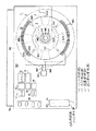
本発明の原理を実施し、また本発明の現在わかっている最良の実施態様を示すディスクドライブを図1に示す。ディスクドライブハウジングは、このディスクドライブの主要部分をなす、改良された小さい外形のディスクスピンドルモータを含むメモリディスク構造3と回転型アクチュエータ構造5を支持するベース1を有する。ベース1はディスクドライブハウジングの一部をなし、ディスクドライブの部品に対する主支持体をなす。
【0012】
メモリディスク構造
メモリディスク構造3は図1には一点鎖線で示すメモリディスクアッセンブリー7とディスクスピンドルモータアッセンブリー9からなる。図1の断面II-IIの図である図2に示すように、メモリディスクアッセンブリー7はこの例では1つのメモリディスク7aしか有しない。ディスクスピンドルモータ9はボビン状のモータロータ9aとプリント回路ステータ巻線9b1を含むモータステータ9b からなる。モータロータ9aのハブ9a1はベース1中に固定されたディスクモータスピンドル9a3上に同軸ベアリング対9a2によって受けられている。ディスクモータスピンドル9a3をベース1に固着するには接着あるいは圧着を用いることができる。2つ以上のメモリディスク7aをメモリディスクアッセンブリー7中に用いてディスクドライブのデータ容量を大きくすることができる。
【0013】
ボビン状のディスクモータロータ9aは軟鋼やステンレス鋼といった磁化可能な材料で製作される。保磁力が弱く、透磁率の高い任意の材料を用いることができる。このボビン状のディスクモータロータ9aはハブ9a1に軸方向に間隔をおいた一対の円形のロータプレート9a4および9a5を有する。下ロータプレート9a4はロータハブ9a1と一体であることが好適である。これは、この構造によれば部品と組み立てステップが1つずつ少なくなるためである。上ロータプレート9a5は、ロータプレート9a4と9a5の軸方向の間隔を決めるハブ9a1の肩部9a6の上に載ることが好適である。接着あるいは圧着によってロータプレート9a5がハブ9a1に固着される。リング状の永久磁石9a7がロータプレート9a4の周辺対向面上に接着され、ディスクモータスピンドル9a3に対し同心状に配設されることとなる。メモリディスク7aは上ロータプレート9a5の上面に接着されている。メモリディスクが入ったときその平坦さを保証するために、ロータプレート9a5の上面はハブへの組み付けとそれに対するメモリディスク7aの取り付けの前にラップ仕上げすることが好適である。
【0014】
スピンドルモータ9のステータ9bはプリント回路板アッセンブリー9b3の薄い基板9b2上の平坦なプリント回路ステータ巻線9b1を有する。プリント回路板アッセンブリー9b3の薄い基板9b2はハウジング内のベース1にメモリディスク構造3とアクチュエータ構造5に沿って固着される。基板9b2はロータハブ9a1への上ローラプレート9a5の固着に先だって設置される。この基板に設けた円形の開口部9b21はロータハブ9a1を通し、それを取り囲む。この位置では、基板9b2はモータロータ9aのロータプレート9a4と9a5の間の位置をとり、その結果プリント回路モータステータ巻線9b1はリング磁石9a7と上ロータプレート9a5の境界面の間の軸方向のギャップの間に入り、この位置では巻線はリング磁石9a7の極性が交互に入れ換わった軸方向の磁界によってリンクされる。
【0015】
図1からわかるように、ステータ巻線9b1はプリント回路板アッセンブリー9b3の基板9b2上のプリント回路レイアウトである。この巻線9b1は径方向に配設された複数のプリント回路巻線部9b11を有し、この巻線部9b11はリング磁石9a7を6つの周方向に等しく間隔をおいた位置において径方向に横切る。これらの径方向の巻線部9b11は内周側巻線部9b12と外周側巻線部9b13を含む連続的なプリント回路巻線パターンの部分をなす。この巻線パターンは基板9b2の両側に正確に位置あわせされた状態で印刷され、これによって2倍の巻き数とモータトルクが得られる。基板9b2の上面のプリント回路巻線の内側の端部は、通孔9b14によって基板9b12の下面上のプリント回路巻線の内側の巻線に接続される。下面の巻線の外側の端部は通孔9b15によって基板9b2の上面に接続される。通孔9b14と通孔9b15はプリント回路パターン9b16および9b17によってプリント回路基板9b2上のアクチュエータ/スピンドルドライバ9b4のスピンドルドライバ9b41に接続される(図3、図7)。
【0016】
リング磁石9a7は図1に示すように6つの周方向に等しく間隔をおいた位置9a71において極性が交互になるように軸方向にスポット磁化される。リング磁石9a7における隣り合う軸方向に交互の極を有する永久磁石スポット9a71の間の磁束結合は、モータロータプレート9a4および9a5の周辺部において周方向になっている。プリント回路巻線9b1が位置する軸方向のギャップは、リング磁石9a7の上面と上ロータプレート9a5の内面の周辺部の間に形成される。
【0017】
ディスクスピンドルモータ9の動作は平コイルリニアモータの動作と同様である。この場合、リニアモータは円形自閉型である。リング磁石9a7とロータプレート9a5の間のエアーギャップ中に軸方向ギャップ磁束路が形成される。この磁束路中の永久磁界はこの軸方向のギャップ中に配設されたプリント回路ステータ巻線9b1の径方向の巻線部9b11を連結する。プリント回路ステータ巻線9b1の径方向の巻線部9b11中の電流はこの永久磁界に対して直角であり、またモータの回転の接線方向成分に対して直角である、これによって、モータロータ9にロータを回転させる電磁結合された接線力が発生する。
【0018】
ディスクスピンドルモータ9が機能するには少なくとも2つの永久磁極9a71が必要である。図6には4つの極を示す。図1に示す6極よりも多い極数を採用することもできる。前述したように、これらの個々の極9a71の軸方向の極性は永久磁石リング9a7の周囲で交互になっている。1つの径方向の巻線部9b11中の電流はハブ9a1から離れる方向に流れ、それに隣り合う径方向の巻線部9b11中の電流はハブ9a1に向かって流れる。プリント回路巻線9b1の径方向の巻線部9b11は軸方向のギャップ中の極が交互になった軸方向の磁束路を横切るため、これらの相互作用する磁束場によって生成される力は常に同方向である。モータロータ9aが回転し、スポット磁石が周方向に隣接する径方向の巻線部9b11に接近すると、プリント回路巻線9b1に結合されたアクチュエータスピンドルドライバ9b4のスピンドルドライバ部9b41は巻線電圧を逆転させて接線力を同じ方向に維持する。リング磁石9a7の周辺位置(図1、図2)に配設された、径方向の巻線部9b11(図1)の位置においてこの位置での軸方向磁界を検出するためのホールセンサー9b18を用いて、この切り換えを開始するすなわちこの切り換えのタイミングを取ることができる。リング磁石9a7の軸方向に極が交互になった磁気スポット9a71の分岐点がホールセンサー9b18に接近し横切るとき、ホールセンサーはスピンドルドライバ9b41に結合される信号を生成し、この信号は単一方向の磁力結合を維持するために、巻線電流の極性の反転が必要であることを示す。あるいは、巻線9bの逆起電力を巻線電流の反転のタイミングを取るための信号源として検出することもできる。
【0019】
図1のアクチュエータスピンドルドライバ9b4のスピンドルドライバ部9b41を、プリント回路巻線9b中の電流の逆転切り換えを行なうための転流回路として図3に詳細に示す。この転流回路は一定の正の電圧Vの供給源とグラウンドの間に接続されたトランジスタブリッジ回路11からなる。トランジスタ対T1、T2およびT3、T4はブリッジ回路11の反対の足(leg)に接続されている。プリント回路モータ巻線9b1はブリッジ回路11の一対の出力端子OT1およびOT2に接続されている。トランジスタ対T1、T2およびT3、T4は2つの状態の間で切り替わり、それによってプリント回路巻線9b1を流れる電流の方向が逆転する。ホールセンサー9b18は正電圧端子Vとグラウンドの間の回路中の正電圧源によって付勢される。ホールセンサー9b18への入力は逆転磁界であり、モータロータ9a7が回転するときこの磁界が加わる。これを図3にホールセンサーの左側の反対方向を向いた矢印で示す。ホールセンサー9b18の出力は、それが図1の径方向巻線部9b11の1つにおける位置で検出する永久磁界の逆転と同期して、同じ極性の2つの異なる電圧値あるいは電圧状態の間で切り替わる。
【0020】
より詳細には、ホールセンサー9b18の出力はプルアップ抵抗R1によって正電圧源Vに接続された端子11aに接続されている。端子11aに現われる電圧は高電圧状態か低電圧状態のいずれかであり、ホールセンサー9b18によって検出される磁束の方向と同期して変化する。端子11aはブリッジ回路11の転流制御回路11bの入力端子である。転流制御回路11bは入力端子11aに並列に接続された2つの転流回路ブランチ11cおよび11dからなる。ブランチ11cは直列接続された反転増幅器I1およびI2からなる。ブランチ11dは1つの反転増幅器I3からなる。したがって、インバータI2およびI3の出力電圧はそれぞれ入力端子11aの電圧がホールセンサー9b18によってその2つの電圧レベルの間で切り換えられるとき、反対の位相の同じ極性の2つの電圧状態の間で変化する。インバータI2の出力電圧はトランジスタ対T1、T2のベース電圧であり、インバータI3の出力電圧はトランジスタ対T3、T4のベースバイアス電圧である。トランジスタT1およびT3のバイアス電圧は、対応するインバータI2およびI3の制御のもとに、それぞれが抵抗器R2およびR3からなる対応する分圧器のタップから得られる。インバータI2の出力がその2つの電圧状態のうち低いほうにあるとき、トランジスタ対T1、T2が導通する。インバータI3の出力がその2つの電圧状態のうち低いほうにあるとき、トランジスタ対T3、T4が導通する。ブリッジ回路に印加される電圧Vが一定の時、モータ速度は一定である。
【0021】
ディスクスピンドルモータ9の速度の制御は、巻線9b1の電圧の大きさを制御するブリッジ回路に結合される電圧を制御するか、あるいはトランジスタT1、T2、T3およびT4のオン状態のデューティサイクルを制御することによって達成することができる。いずれの種類の制御も、磁気ヘッドによってメモリディスクから得られるタイミングパルスの発生によってほぼ一定のモータ速度を維持する、ブリッジ回路11に供給される電圧の大きさを制御する、あるいはブリッジ回路11に結合される一定の電圧のデューティサイクルを変調するように調整することができる。かかる速度調整は本発明には含まれない。
【0022】
ディスクスピンドルモータアッセンブリー9のボビン状のロータ9aの変更態様を図4に示す。1.8、1.3およびそれ以下の小さな形状係数のディスクドライブの製作においては、部品点数の低減と組み立てステップ、特に小型部品の組み立てステップの低減が重要である。この目的のために、図4(これも図2のII-IIにおける断面図である)には、単体構造のボビン状のモータロータ9aを示す。上述した小さい形状係数においては、かかる部品はたとえばねじ切り盤や成型を用いて単体部品として製作するのが簡便な方法である。別々のモータロータ部品の管理が不要になり、また少なくとも1つの難しい組み立てステップが削除される。
【0023】
単体のボビン状モータロータを用いるには、図1および図2に示すディスクドライブの組み立てに用いられるものとは異なるディスクドライブ組み立て処理が必要であり、またプリント回路アッセンブリーをモータロータの上ロータプレート9a4と下ロータプレート9a5の間に入れるための変更が必要である。図5に示すように、プリント回路アッセンブリーは向かって右の端部から入れられる。図1の巻線配置ではかかるスロットは不可能であるが、巻線9b1を基板9b2上で60°回転させ、巻線部9b13をロータハブ9a1を迂回して引き回すことによって、スロット9b22を内側に伸張させてロータハブ9a1を通過させることができる。この巻線部の励磁は図3の転流回路を用いて図1を参照して説明した通りである。
【0024】
スロットを設けた基板9b2上の巻線構成の他の変更態様を図6に示す。この巻線はスロットの両側に配置された2つの別々の巻線部9b1aと9b1bからなる。この巻線パターンには別々の巻線部9b1aおよび9b1bのそれぞれに2つずつの4つの径方向の巻線部9b11が設けられている。4つの等間隔の極が軸方向に交互になった永久磁石スポット9a71がリング磁石9a7に設けられて、軸方向の磁界が発生する。図1および図5の巻線の場合と同様に、径方向の巻線部9b11中の電流はそれを通過する磁化されたスポット9a71の動きと同期して逆転しなければならない。これを達成するためには、電流の逆転がすべての径方向巻線部9b11において同時に起こるように、別々の巻線部9b1aおよび9b1bをスピンドルドライバ9b41に並列に接続しなければならない。図3の転流回路をここでも用いることができる。図1および図5の巻線構成と同様に、図3のブリッジ回路11の出力端子OT1、OT2と並列に接続される図6の別々の巻線部9b1aおよび9b1bは、同時に切り換えられて径方向の巻線部9b11における電流の逆転が達成される。
【0025】
アクチュエータ構造
図1に示すように、回転型アクチュエータアーム構造5は少なくとも1つの可撓性のアーム5aからなる。アクチュエータアーム5aはメモリディスク7aの上面に重なる。図2のジンバルばね5a1がトランスデューサアッセンブリー5bを可撓性アーム5aの末端部に取り付ける。トランスデューサアッセンブリー5bはスライダ5b1と磁気ヘッド5b2等の読み出し/書き込み要素からなる。図2および図4はディスクドライブの各部の関係を示し、図中、メモリディスクアッセンブリー7は単一のディスク7aからなる。図2および図4には、アクチュエータ/トランスデューサアッセンブリーをメモリディスク7aの上面にのみ示すが、第2のかかるアッセンブリーをメモリディスク7aの下面にも配置することができることは明らかである。また、本発明は図7に示すように2つ以上のメモリディスクを用いて実施することもできる。
【0026】
アクチュエータアーム構造5はベース1に固着されたスピンドル5d上に受けられた円筒状のハブ5c(図1)に取り付けられている。
【0027】
回転型アクチュエータアーム5はハブ5dのアクチュエータ構造に固着された平形コイル5e1を有するアキシャルギャップアクチュエータモータ5eからなる。コイル5e1は、ベース1に固着された永久磁石アクチュエータモータステータ5e3の上下のステータプレート5e2(図1には上のプレートだけを示す)の間の軸方向磁界の中でスピンドル5dのまわりの平面的な円弧状のパスを揺動する。コイル5e1が両方向に付勢されることによって、トラックセンサーとしてサーボループ中の磁気ヘッドを用いる回転形アクチュエータアッセンブリー5のトラック探索追跡機能が制御される。図1に示すように、プリント回路板アッセンブリー9b3には開口部5e4が設けられ、アキシャルギャップアクチュエータモータ5eの永久磁石ステータ5e3をベース1に直接取り付けられるようになっている。
【0028】
可撓性アーム5aのエッジに沿って伸張するワイヤ5f1が磁気ヘッド5b2を回転型アクチュエータ5のハブ5cにある個々の接着パッド5f2に接続する。他のワイヤ5f3がアキシャルギャップアクチュエータモータ5eのコイル5e1をアクチュエータハブ5cにある他の個々の接着パッド5f2に接続する。複数の回路パターンを有する平坦な可撓性のケーブル5f4がアクチュエータハブ5cの接着パッド5f2をプリント回路板アッセンブリー9b3上の他の接着パッド5f5に接続する。この位置から、プリント回路板の回路パターン(図示せず)は磁気ヘッド5b2を前置増幅器20と読み出し/書き込み増幅器21を含む読み出し/書き込みチャンネル(図7参照)に、またアクチュエータモータ5eのコイル5e1をプリント回路板アッセンブリー9b3上のスピンドル/アクチュエータドライバ9b4(図7参照)に接続して、位置決め磁気ヘッド5b2を制御するのに用いられる。
【0029】
プリント回路板がディスクドライブハウジングの外部に取り付けられる従来のディスクドライブにおいては通常ディスクドライブハウジングの下側に行なわれるこれらの回路接続はすべて、ディスクドライブハウジングの内部に入っており、それによって電気ケーブル接続をハウジングの開口部やコネクタを介してプリント回路板やその上の電気素子に対して行なう必要がなくなる。ディスクドライブハウジングの側面に配設されたコネクタ5gはディスクドライブとディスクドライブの外部にあるホストコンピュータの間の電気的接続を提供する。
【0030】
読み出し/書き込み機能の実行中のトラック探索追跡動作モードにおいてディスクドライブを制御するための電子部品およびシステムはすべてプリント回路板アッセンブリー9b3に取り付けられ、ここに開示した独特の構成法によって、ディスクドライブハウジング1の内部においてディスクスピンドルモータ9およびアクチュエータ5と機能的にも構造的にも統合されている。
【0031】
メモリディスク7aに記録されたすべてのデータはトラックおよびトラックセクタによって決まる位置に記録される。トラックの発見には2つの方法がある。1つは現在のトラックから径方向にトラックをカウントする方法であり、もう1つは個々のトラックに記録されたトラック番号による方法である。
【0032】
図1に示すような1つの磁気ヘッドがトラック探索とトラック追跡のための埋め込み型サーボコードと呼ばれるサーボコードを読み、サーボコードのバースピンドルとの間のデータセクタ中のトラックに対してデータの読み出しおよび書き込みを行なう。図7に示すように、ディスクスタック中に多数のディスクが各ディスク面用のトランスデューサとともに用いられる場合、1つのディスク面mすなわち一番下のディスクの下面をサーボコード専用とすることができ、この場合、磁気ヘッド5b21がサーボコード専用とされる。これらの異なる機能のタイミングは選択されたトラック中のアドレス指定されたセクタ中のサーボコード記録の始点あるいはデータ記録の始点に応じて磁気ヘッドから送られる信号によって起動されるインターフェース15によって提供される。
【0033】
図1および図4は本発明の物理的側面と機能的側面を関係付けるものであり、電子構成要素をブロック図の形態で示す。実際には、これらのブロックは、図1に示すようにプリント回路板アッセンブリー9b3の基板上に配置され、プリント回路パターン(図示せず)によって接続されてこのディスクドライブ制御システムの構成要素として機能する電子回路チップあるいはその他の分離した回路素子からなる。図7に示すように、この制御システムはいくつかのシステム構成要素間の接続を示す。このシステムはホストコンピュータ19とディスクメモリファイルあるいは駆動装置5、7の間の双方向の通信を提供する機能をはたす。
【0034】
図7に示すように、(図1も参照)、ホストコンピュータ19はコネクタ5gを介してインターフェース回路15に接続されている。ホストコンピュータ19によるディスクメモリ5、7からのデータの読み出し、あるいはディスクメモリ5、7へのデータの書き込みの要求はインターフェース15のインターフェース制御部15aで受け取られ、インターフェース15によって処理されてデータの検索あるいは書き込みが行なわれるべきトラックアドレスとトラックセクタアドレスが得られる。かかる処理は主として必要に応じて外部の読み出し専用メモリ(ROM)16にアクセスするマイクロプロセッサ15bによって行なわれる。トラックカウント値あるいはトラック番号の形態のトラックアドレスが、どちらのトラック同定形式あるいはアドレス形式が取られるかに応じて、インターフェース15からデータコントローラ15cを介してディスクコントローラ17に送られる。トラックアドレスとセクタアドレスはマイクロプロセッサ15b中のランダムアクセスメモリに格納される。バッファRAM15dは読みだし/書き込みデータを備える。
【0035】
ディスクコントローラ17はアクチュエータ/スピンドルドライバ9b4を介して回転型アクチュエータモータ5eとディスクスピンドルモータ9の制御を行なう。アクチュエータ/スピンドルドライバ9b4中のスピンドルドライバ9b41は、ディスクコントローラ17に応答して、ディスクアッセンブリー7のスピンアップを開始し、ディスクスピンドルモータ9の速度を調整する。アクチュエータ/スピンドルドライバ9b4の位置コントローラ9b42と増幅器9b43が、トラックカウント値あるいはトラック番号に関するディスクコントローラ17からの入力に応じて、回転型アクチュエータモータ5eを制御し、これによってトラック探索が開始される。位置コントローラ9b42と増幅器9b43は、探索動作モード中にトラックの横断あるいはトラック番号に関して磁気ヘッド位置のフィードバックを受け取る位置センサー9b44を含む閉サーボループの一部をなす。複数ディスクを用いるディスクメモリの場合には、フィードバックは選択された磁気ヘッド5b2を介して埋め込み型サーボコードから得ることができ、あるいはまた専用の磁気ヘッド5b21を介して専用のサーボコードから得ることもできる。トラック横断数あるいはトラック番号が位置コントローラ9b42のそれと一致するとき、トラック探索が終了しトラック追跡が開始される。
【0036】
トラック追跡モードにおいては、専用のサーボ機能が選択されないものとすると、磁気ヘッド5b2は追跡されるトラックのそれぞれのトラックセクタ中の埋め込み型サーボコードのバーストを検出し、データアドレスを検出し、データコードの始点を検出する。インターフェース15に結合された前置増幅器20と読み出し/書き込み増幅器21を含む読み出し/書き込みチャンネル中のこれらの信号は読み出しあるいは書き込み機能を開始させる。読み出されたデータはディスクからバッファRAMに転送され、書き込みデータはバッファコントローラ14の制御のもとにバッファRAMからディスクに転送される。
【0037】
読み出し/書き込みチャンネルにおいて、前置増幅器20はトランスデューサあるいはヘッドインターフェースとして機能する。サーボコード、アドレスコードあるいはデータコードの始点から磁気ヘッド中に誘起された信号は、読み出し/書き込み増幅器21にパルスとして送出される。ここでは、埋め込み型サーボコードから得られた信号はパルス検出器21aによってこの閉サーボループ中の位置センサー9b44にフィードバックされ、これによってサーボコードフィールドの横断中にトラック追跡が維持され、アドレスコードとデータコードの始点から得られたパルスがクロック同期位相同期ループ21bを介して読み出し/書き込みエンコーダ回路21cに送出される。説明上、回路21bはその入力に位相比較器を有し、その出力に電圧制御発振器(VCO)を有する。これらはローパスフィルターと積分器によって結合される。この回路は符号化されたデータストリームからクロック発生器CGのクロックを抽出する機能を果たす。デコーダ/エンコーダ21cはシステムのディスクメモリ側の1,7あるいは2,7コードのデータをシステムのインターフェース/ホストコンピュータ側でNRZコードに変換する。データフレーム化および制御回路15eが書き込みを行なうべきセクタを構築するか、あるいは読み出し済みのセクタを分解する。このセクタはデータの他にオーバーヘッド情報を含む。
【0038】
コネクタ回路15fを用いてデータの直列化/非直列化を行なう。読み出し中直列データストリームは並列データに変換される。書き込むべき並列フォーマットのデータは直列データストリームに変換される。この位置には誤り修正回路を用いることも有益である。
【0039】
図1と図7の比較から、いくつかの電子システム、メモリ、増幅器その他の間の主要な接続が説明される。これらはプリント回路アッセンブリー9b3の一部をなすプリント回路パターン中に組み込まれていることがわかる。かかるプリント回路設計の詳細は本発明に関してはその実施例には重要ではない。
【0040】
本発明は光学ディスクドライブ、磁気光学ディスクドライブ、磁気抵抗ディスクドライブおよびその他の種類のディスクドライブに適用することができる。
【0041】
以上、本発明の実施例について詳述したが、以下、本発明を各実施態様毎に列挙する。
【0042】
1. a. ベースを有するハウジングと、
b. ハブと該ハブ上に軸方向に間隔をおいた一対の磁性材料からなるロータプレートを備えるモータロータと、
c. 前記ベース上に前記モータロータを回転可能に取り付けるための手段と、
d. 前記モータロータに所定の径寸法を有するディスクを同心状に接続する手段と、
e. 前記ロータプレートの周辺部に隣接して、前記一対のロータプレートの間に極性が交互で周方向に間隔をおいた軸方向の磁界を発生させる手段と、
f. その一部が前記ロータプレートの間に配設された前記ベース上に設けられた回路板と、
g. 前記軸方向の磁界のうちの少なくともいくつかにある前記回路板の一部に配設されたモータ巻線と、
h. トランスデューサと、
i. 前記トランスデューサを前記ディスクの径方向の寸法内の異なる径方向の位置に移動させるための前記ベースに移動可能に取り付けられた可動トランスデューサアクチュエータ手段と
からなるディスク記録/再生装置。
【0043】
2. a. 前記軸方向の磁界を発生させるための手段が、前記ハブに対して同心状に前記ロータプレートの間で該一方のロータプレートに固着された円形の永久磁石リングからなり、該永久磁石リングは前記ロータプレートの間に前記の磁界を発生させるための極性が交互で周方向にほぼ等間隔の軸方向に磁化された永久磁石スポットを有してなる前項1記載のディスク記録/再生装置。
【0044】
3. a. 前記モータ巻線がプリント回路巻線である前項1記載のディスク記録/再生装置。
【0045】
4. a. 前記回路板がプリント回路板からなり、
b. 前記モータ巻線が前記軸方向の磁界中の前記プリント回路板の両面の連続的なプリント回路巻線部からなるプリント回路巻線である前項1記載のディスク記録/再生装置。
【0046】
5. a. 前記プリント回路巻線部がそれぞれ前記軸方向の磁界によって連結される径方向の巻線部からなり、該径方向の巻線部の数が軸方向の磁界の数と等しい前項4記載のディスク記録/再生装置。
【0047】
6. a. 前記プリント回路板上の転流回路と、
b. 前記転流回路を前記プリント回路巻線部に接続する前記プリント回路板上のプリント回路パターンと、
c. 前記転流回路を制御するため前記モータロータの回転中に軸方向の磁界を通過して該磁界と磁束結合する状態で径方向の巻線部に隣接して配設された磁界センサーを有する前項5記載のディスク記録/再生装置。
【0048】
7. a. 前記モータロータが単体の磁性材料からなるものである前項1記載のディスク記録/再生装置。
【0049】
8. a. 前記一方のロータプレートが前記ハブと一体であり、前記他方のロータプレートが前記ハブに取り付けられた前項1記載のディスク記録/再生装置。
【0050】
9. a. 前記可動トランスデューサアクチュエータ手段が回転型アクチュエータである前項1記載のディスク記録/再生装置。
【0051】
【発明の効果】
以上のように、本発明はディスクスピンドルモータをディスクドライブのベースとハウジングに一体化し、ディスクスピンドルモータの独特な設計によって可能なプリント回路板アッセンブリーのディスクドライブハウジングへの組み込みによって、プリント回路板の電子部品をハウジング内のディスクドライブモータ、アクチュエータモータおよび磁気ヘッドと一体化し、ディスクスピンドルモータの機能的部分としてのディスクドライブベースとプリント回路板アッセンブリーを用いる。これによって、製造コスト、組み立てコストおよび作業が低減される。プリント回路板アッセンブリー上のプリント回路を用いることによって、特にディスクスピンドルモータ巻線については、ディスクスピンドルモータ内の巻コイルが不要になり、このアッセンブリーにはディスクスピンドルモータのための別途の外部ハウジングが不要であり、モータハウジングはディスクドライブのベースあるいはハウジングであり、プリント回路巻線を含むモータステータはこれもハウジング内のディスクドライブのベース上にあるプリント回路板アッセンブリーの一部である。
【0052】
このディスクスピンドルモータ設計は、すべての電子的および電気的機能を1つの共通のプリント回路板アッセンブリーに統合することを可能にする。このプリント回路板アッセンブリーの基板は、ハウジング内の金属の駆動装置ベースに接着して支持することのできる薄い低コストの材料(薄いガラス繊維、ポリイミドその他)で製作される。集積回路チップ、コネクタおよびその他の分離した電気あるいは電子素子はこのプリント回路基板に接着される。また、このプリント回路基板の一部はディスクスピンドルモータ巻線を支持するディスクスピンドルモータステータとしても機能する。
【0053】
このプリント回路基板9b2は非常に低コストでバッチ生産することができ、すなわち(1)電子部品の基板、(2)スピンドルモータステータ、(3)コネクタ基板、(4)すべての電気的および電子的構成要素のための単一の相互接続手段、(5)かかる回路接続はすべてハウジングの内部にあり、外部の回路基板への接続のためにハウジングに開口部を設ける必要がないといった多数の機能を果たす。このバッチ生産される部品への唯一の外部取り付け物はアクチュエータアームアッセンブリーからの可撓性のケーブルである。基板がポリイミドである場合、この可撓性のケーブルは基板への付属物としてに示すような接続を削除することができる。
【0054】
このディスクスピンドルモータの設計は簡単であるため、従来のディスクスピンドルモータにくらべて大幅なコストダウンが可能である。印刷されたコイル以外に必要な構成要素は(1)たとえば軸方向のベアリング対からなるカートリッジベアリングアッセンブリー、(2)磁石、および(3)ディスクモータロータ、好適にはモータの磁束路としてもはたらくボビン状のロータのみである。モータロータは外形が小さく、これは超薄型ディスクドライブにおけるディスクスピンドルモータのアプリケーションには欠かすことのできない特徴である。
【図面の簡単な説明】
【図1】本発明の原理を実現したメモリディスク構造とアクチュエータ構造を有するディスクドライブ等に用いられるディスク記録/再生装置の平面図である。
【図2】図1の線II-IIにおける図1のメモリディスク構造の断面図である。
【図3】ディスクスピンドルモータの巻線の励起を制御する回路図である。
【図4】図2のメモリディスク構造の変更態様を示す図1の線II-IIにおける断面図である。
【図5】図1に示す種類のディスク記録/再生装置の平面図であり、ディスクスピンドルモータプリント回路巻線の異なる配置を示す。
【図6】図1に示す種類のディスク記録/再生装置の平面図であり、ディスクスピンドルモータプリント回路巻線の異なる構成を示す。
【図7】基本回路要素間の電気的接続を示すサーボ機能および処理機能を用いたディスクドライブシステムの図である。
【符号の説明】
1: ベース
3: メモリディスク構造
5: 回転型アクチュエータ構造
5a: 可撓性のアーム
5a1: ジンバルばね
5b: トランスデューサアッセンブリー
5b2: 磁気ヘッド
5b21: 磁気ヘッド
5c: 円筒状のハブ
5d: スピンドル
5e: アキシャルギャップアクチュエータモータ
5e1: 平形コイル
5e2: ステータプレート
5e3: 永久磁石アクチュエータモータステータ
5e4: 開口部
5f1: ワイヤ
5f2: 接着パッド
5f3: ワイヤ
5f4: 可撓性のケーブル
5f5: 接着パッド
5g: コネクタ
7: メモリディスクアッセンブリー
7a: メモリディスク
9: ディスクスピンドルモータアッセンブリー
9a: モータロータ
9a1: ハブ
9a2: 同軸ベアリング対
9a3: ディスクモータスピンドル
9a4: 下ロータプレート
9a5: 上ロータプレート
9a6: ハブ9a1の肩部
9a7: リング状の永久磁石
9a71: 永久磁石スポット
9b: モータステータ
9b1: プリント回路ステータ巻線
9b1a, 9b1b: 巻線部
9b2: 基板
9b3: プリント回路板アッセンブリー
9b4: スピンドル/アクチュエータドライバ
9b11: 径方向の巻線部
9b12: 内周側巻線部
9b13: 外周側巻線部
9b16, 9b17: プリント回路パターン
9b18: ホールセンサー
9b21: 開口部
9b41: スピンドルドライバ
9b42: 位置コントローラ
9b43: 増幅器
9b44: 位置センサー
11: トランジスタブリッジ回路
11a: 端子
11b: 転流制御回路
11c, 11d: 転流回路ブランチ
11, 12: 反転増幅器
13: 反転増幅器
15a: インターフェース制御
15b: マイクロプロセッサ
15c: データコントローラ
15d: バッファコントローラ
15e: データフレーム化および制御回路
15f: コネクタ回路
16: 読み出し専用メモリ
17: ディスクコントローラ
19: ホストコンピュータ
20: 前置増幅器
21: 読み出し/書き込み増幅器
21b: クロック同期位相同期ループ
21c: 読み出し/書き込みエンコーダ回路
T1、T2: トランジスタ対
T3、T4: トランジスタ対
OT1、 OT2: 出力端子
R1: プルアップ抵抗
V: 正電圧源
R2, R3: 抵抗器[0001]
[Industrial application fields]
The present invention relates to a disk recording / reproducing apparatus, and more particularly, it is easy to manufacture parts and sub-assemblies, is easy to assemble, improves product yield, reduces product cost, and is used in a conventional assembly stack. It relates to such a device using a structural design that improves mechanical volumetric efficiency by functionally integrating parts that are physically separated and not functionally related to reduce the profile of the device.
[0002]
[Prior art]
A recording / reproducing apparatus typically includes a rotatable disk medium structure including a disk driven by a disk spindle motor, and a transducer / actuator arm assembly driven by an actuator motor on a movable support to move the transducer in the radial direction of the disk. An actuator structure having This actuator may be rotary or reciprocating and is controlled by a servo-controlled actuator motor to move the transducer to different radial positions on the disk. In the disk drive, this operation mode is called track search / tracking operation.
[0003]
In a disk drive, the memory disk structure is concentrically mounted around a disk spindle hub driven by a radial gap disk spindle motor having a stator attached to the base of the disk drive housing in the memory disk assembly. Consists of one or more disks. In this memory disk assembly, one or more disks are held in a stack around a disk spindle hub, and a number of disks have ring spacers with a thickness sufficient to allow spacing of individual actuator structures therebetween. Provides an axial spacing. The stator of the disk spindle motor is assembled in a disk spindle hub. The disk spindle hub functions as the rotor of this motor.
[0004]
[Problems to be solved by the invention]
As the size of the disk decreases, the motor design in the memory disk structure becomes impractical in both radial and axial dimensions. When the radius becomes small, an appropriate motor torque cannot be obtained. As a result of design efforts to increase the motor torque by increasing the motor radius and decreasing the axial dimension, a relatively thin and flat radial gap disk spindle motor with a diameter that meets the motor torque requirements was developed. It was. A stator structure having blades is disposed in the rotor of the motor. The motor rotor of this type of disk spindle motor has a large diameter with respect to the size of the memory disk, and therefore cannot be arranged in the memory disk stack, so that the memory disk and the disk spindle motor are integrated in the axial direction. This motor design has a small outer shape and improves motor torque. This design integrates the disk spindle motor and memory disk in the axial direction instead of concentrating the disk stack around the motor, resulting in some reduction in volumetric efficiency. There is a need not only to further reduce the thickness or outer shape of the disk spindle motor, but also to reduce the thickness of the recording / reproducing apparatus.
[0005]
[Means for Solving the Problems]
The best embodiment of the present invention is realized in a rotary actuator type disk drive, which is used here as an example to illustrate the present invention. Applications of the present invention to reciprocating actuator disk drives and rotary actuator disk drives other than those described herein, such as any disk recording / reproducing apparatus using rotating media, are within the scope of those skilled in the art. Think.
[0006]
If the shape factor is reduced, the amount of information stored is increased, and the price of the drive unit is reduced, it may be cost-effective or impossible to perform large-scale manual operations for fabrication and assembly of parts. . The present invention provides a new method of configuring a disk drive, in particular a new configuration of a spindle motor such that the number of parts is reduced and a method of integrating it in the disk drive, and is simplified to adapt to automatic fabrication and assembly. Component parts, minimizing manual operations in disk drive fabrication and assembly processes, reducing test conditions and improving product yield, resulting in a durable product suitable for the application and environment. It is done.
[0007]
The disk spindle motor of the present invention and its integration into the disk drive employs a unique structure that reduces the number of parts required for the disk drive assembly and adapts the parts to automated manufacturing and assembly techniques. This is accomplished by integrating the disk spindle motor into the disk drive housing and printed circuit assembly. An axial gap permanent magnet disk spindle motor having a bobbin-shaped motor rotor is used. The bobbin-shaped motor rotor is rotatably received in a disk drive housing on the housing base and has a pair of circularly spaced rotor plates provided on the hub. An axial magnetic field in which discrete polarities are alternately reversed is generated between the circular rotor plates. Planar disk spindle stator motor windings and circuitry are fabricated on the base of the disk drive housing as part of the printed circuit board assembly. The printed circuit board assembly is attached to a base in a disk drive housing and has a portion for carrying a planar winding that is fitted between circular rotor plates spaced axially apart. The planar winding can be constituted by a mold winding, but is preferably constituted by a printed circuit. This greatly reduces manual labor in the production and assembly of parts. This unique structural design feature makes it possible to print from an underlying position outside the disk drive to an existing space in the disk drive, for some form factors, as well as for conventional designs, for the motor itself, The removal of the circuit assembly also reduces the profile size of the disk spindle motor, thereby improving mechanical volumetric efficiency.
[0008]
Further, the base of the disk drive housing and the electronic components of the printed circuit assembly are incorporated into the disk drive housing as an integral part of the disk spindle motor. The disk spindle motor winding is a printed circuit on the printed circuit board assembly. In this embodiment, electronic components and electrical functions are packaged together on a common printed circuit board. The printed circuit board is thin and made of a low-cost material such as glass fiber or polyimide, and is bonded to the disk drive base in the housing along the memory disk structure and the rotary actuator structure. In addition to the printed circuit windings of the disk spindle motor, integrated circuits, connectors and separate circuit elements are bonded to the printed circuit board.
[0009]
By using an axial gap disk spindle motor that is integrated with the base of the disk drive and provided with printed circuit windings, the outer diameter of the disk spindle motor can be reduced and the printed circuit assembly can be placed in the disk drive housing, The further increase in the external dimensions of the disk drive usually caused by the printed circuit assembly board is prevented. Such cumulative reduction in structural outline reduces the overall outline of the memory disk structure and disk drive housing, and improves the mechanical volumetric efficiency of the disk drive. This ensures that all connections between the disk drive and the electronic components are made within the disk drive housing, and the complexity of the electrical connections in the housing extends to the external printed circuit board assembly, which can cause contaminants. Leakage is prevented.
[0010]
This unique structure of this disc drive requires fewer parts, uses components that are configured for automatic manufacturing and assembly, minimizes the need for manual manufacturing and assembly, and reduces product yield. This makes it possible to manufacture a disk spindle motor for a disk drive having a smaller shape factor at a low cost.
[0011]
【Example】
A disk drive embodying the principles of the present invention and illustrating the best presently known embodiment of the present invention is shown in FIG. The disk drive housing has a
[0012]
Memory disk structure
The
[0013]
The bobbin-shaped disc motor rotor 9a is made of a magnetizable material such as mild steel or stainless steel. Any material having a low coercive force and high magnetic permeability can be used. The bobbin-shaped disc motor rotor 9a has a pair of circular rotor plates 9a4 and 9a5 spaced apart in the axial direction on a hub 9a1. The lower rotor plate 9a4 is preferably integral with the rotor hub 9a1. This is because according to this structure, one part and one assembly step are reduced. The upper rotor plate 9a5 is preferably placed on the shoulder 9a6 of the hub 9a1 that determines the axial distance between the rotor plates 9a4 and 9a5. The rotor plate 9a5 is fixed to the hub 9a1 by adhesion or pressure bonding. A ring-shaped permanent magnet 9a7 is bonded onto the peripherally opposed surface of the rotor plate 9a4 and is arranged concentrically with the disk motor spindle 9a3. The memory disk 7a is bonded to the upper surface of the upper rotor plate 9a5. In order to ensure the flatness of the memory disk when it is inserted, it is preferable that the upper surface of the rotor plate 9a5 be lapped before assembly to the hub and attachment of the memory disk 7a thereto.
[0014]
The
[0015]
As can be seen from FIG. 1, the stator winding 9b1 is the printed circuit layout on the substrate 9b2 of the printed circuit board assembly 9b3. This winding 9b1 has a plurality of printed circuit winding portions 9b11 arranged in the radial direction, and this winding portion 9b11 crosses the ring magnet 9a7 in the radial direction at equally spaced positions in six circumferential directions. . These radial winding portions 9b11 form a part of a continuous printed circuit winding pattern including an inner peripheral winding portion 9b12 and an outer peripheral winding portion 9b13. This winding pattern is printed in an accurately aligned state on both sides of the substrate 9b2, thereby obtaining twice the number of turns and motor torque. The inner end of the printed circuit winding on the upper surface of the substrate 9b2 is connected to the inner winding of the printed circuit winding on the lower surface of the substrate 9b12 through the through hole 9b14. The outer end of the lower winding is connected to the upper surface of the substrate 9b2 through a through hole 9b15. The through holes 9b14 and 9b15 are connected to the spindle driver 9b41 of the actuator / spindle driver 9b4 on the printed circuit board 9b2 by the printed circuit patterns 9b16 and 9b17 (FIGS. 3 and 7).
[0016]
As shown in FIG. 1, the ring magnet 9a7 is spot-magnetized in the axial direction so that the polarities are alternated at the positions 9a71 equally spaced in the six circumferential directions. The magnetic flux coupling between the permanent magnet spots 9a71 having alternating poles in the adjacent axial direction in the ring magnet 9a7 is in the circumferential direction at the periphery of the motor rotor plates 9a4 and 9a5. An axial gap in which the printed circuit winding 9b1 is located is formed between the upper surface of the ring magnet 9a7 and the peripheral portion of the inner surface of the upper rotor plate 9a5.
[0017]
The operation of the
[0018]
For the
[0019]
[0020]
More specifically, the output of the hall sensor 9b18 is connected to the terminal 11a connected to the positive voltage source V by the pull-up resistor R1. The voltage appearing at the terminal 11a is either a high voltage state or a low voltage state, and changes in synchronization with the direction of the magnetic flux detected by the Hall sensor 9b18. The terminal 11a is an input terminal of the commutation control circuit 11b of the
[0021]
The speed of the
[0022]
A modification of the bobbin-shaped rotor 9a of the disk
[0023]
In order to use a single bobbin-shaped motor rotor, a disk drive assembly process different from that used for assembling the disk drive shown in FIGS. 1 and 2 is required, and the printed circuit assembly is connected to the upper rotor plate 9a4 and the lower rotor plate 9a4. It is necessary to change the rotor plate 9a5. As shown in FIG. 5, the printed circuit assembly is inserted from the right end toward it. Although such a slot is not possible with the winding arrangement of FIG. 1, the slot 9b22 extends inward by rotating the winding 9b1 by 60 ° on the substrate 9b2 and routing the winding 9b13 around the rotor hub 9a1. It is possible to pass through the rotor hub 9a1. The excitation of the winding portion is as described with reference to FIG. 1 using the commutation circuit of FIG.
[0024]
FIG. 6 shows another modification of the winding configuration on the board 9b2 provided with slots. This winding consists of two separate winding portions 9b1a and 9b1b arranged on both sides of the slot. This winding pattern is provided with four radial winding portions 9b11, two for each of the separate winding portions 9b1a and 9b1b. A permanent magnet spot 9a71 in which four equally spaced poles are alternately arranged in the axial direction is provided on the ring magnet 9a7 to generate an axial magnetic field. As in the windings of FIGS. 1 and 5, the current in the radial winding 9b11 must be reversed in synchronism with the movement of the magnetized spot 9a71 passing through it. To achieve this, separate windings 9b1a and 9b1b must be connected in parallel to the spindle driver 9b41 so that current reversal occurs in all radial windings 9b11 simultaneously. The commutation circuit of FIG. 3 can also be used here. Similar to the winding configurations of FIGS. 1 and 5, the separate winding portions 9b1a and 9b1b of FIG. 6 connected in parallel with the output terminals OT1 and OT2 of the
[0025]
Actuator structure
As shown in FIG. 1, the rotary actuator arm structure 5 comprises at least one flexible arm 5a. The actuator arm 5a overlaps the upper surface of the memory disk 7a. A gimbal spring 5a1 in FIG. 2 attaches the
[0026]
The actuator arm structure 5 is attached to a cylindrical hub 5c (FIG. 1) received on a spindle 5d fixed to the
[0027]
The rotary actuator arm 5 comprises an axial gap actuator motor 5e having a flat coil 5e1 fixed to the actuator structure of the hub 5d. The coil 5e1 is planar around the spindle 5d in an axial magnetic field between the upper and lower stator plates 5e2 (only the upper plate is shown in FIG. 1) of the permanent magnet actuator motor stator 5e3 fixed to the
[0028]
Wires 5f1 extending along the edges of the flexible arm 5a connect the magnetic head 5b2 to individual bond pads 5f2 on the hub 5c of the rotary actuator 5. Another wire 5f3 connects the coil 5e1 of the axial gap actuator motor 5e to another individual bond pad 5f2 on the actuator hub 5c. A flat flexible cable 5f4 having a plurality of circuit patterns connects the adhesive pad 5f2 of the actuator hub 5c to another adhesive pad 5f5 on the printed circuit board assembly 9b3. From this position, the circuit pattern (not shown) on the printed circuit board causes the magnetic head 5b2 to be in the read / write channel (see FIG. 7) including the
[0029]
In conventional disk drives where the printed circuit board is mounted outside the disk drive housing, all of these circuit connections normally made on the underside of the disk drive housing are contained within the disk drive housing, thereby providing electrical cable connections. Is not required to be performed on the printed circuit board or the electrical elements on the printed circuit board via the opening of the housing or the connector. A
[0030]
All the electronic components and systems for controlling the disk drive in the track search and tracking mode of operation during execution of the read / write function are mounted on the printed circuit board assembly 9b3, and the
[0031]
All data recorded on the memory disk 7a is recorded at a position determined by the track and the track sector. There are two ways to find a track. One is a method of counting tracks in the radial direction from the current track, and the other is a method based on track numbers recorded in individual tracks.
[0032]
One magnetic head as shown in FIG. 1 reads a servo code called an embedded servo code for track search and track tracking, and reads data from a track in a data sector between the servo code and the bar spindle. And write. As shown in FIG. 7, when multiple disks are used in a disk stack with a transducer for each disk surface, one disk surface m, ie the bottom surface of the bottom disk, can be dedicated to the servo code. In this case, the magnetic head 5b21 is dedicated to the servo code. The timing of these different functions is provided by an
[0033]
1 and 4 relate the physical and functional aspects of the present invention and show the electronic components in block diagram form. In practice, these blocks are arranged on the substrate of the printed circuit board assembly 9b3 as shown in FIG. 1 and are connected by a printed circuit pattern (not shown) to function as components of this disk drive control system. It consists of an electronic circuit chip or other separate circuit element. As shown in FIG. 7, the control system shows connections between several system components. This system functions to provide bi-directional communication between the host computer 19 and the disk memory file or drive unit 5,7.
[0034]
As shown in FIG. 7 (see also FIG. 1), the host computer 19 is connected to the
[0035]
The
[0036]
In the track tracking mode, if the dedicated servo function is not selected, the magnetic head 5b2 detects the burst of embedded servo code in each track sector of the track to be tracked, detects the data address, and detects the data code. Detect start point of. These signals in a read / write channel including a
[0037]
In the read / write channel, the
[0038]
Data is serialized / deserialized using the connector circuit 15f. During reading, the serial data stream is converted to parallel data. The parallel format data to be written is converted to a serial data stream. It is also beneficial to use an error correction circuit at this location.
[0039]
From the comparison of FIGS. 1 and 7, the main connections between several electronic systems, memories, amplifiers, etc. are described. It can be seen that these are incorporated in the printed circuit pattern forming part of the printed circuit assembly 9b3. The details of such printed circuit design are not critical to the embodiment of the present invention.
[0040]
The present invention can be applied to optical disk drives, magneto-optical disk drives, magnetoresistive disk drives, and other types of disk drives.
[0041]
As mentioned above, although the Example of this invention was explained in full detail, hereafter, this invention is enumerated for every embodiment.
[0042]
1. a. a housing having a base;
b. a motor rotor comprising a hub and a rotor plate made of a magnetic material spaced apart in the axial direction on the hub;
c. means for rotatably mounting the motor rotor on the base;
d. means for concentrically connecting a disk having a predetermined diameter to the motor rotor;
e. means for generating an axial magnetic field adjacent to the periphery of the rotor plate and alternately spaced in the circumferential direction between the pair of rotor plates;
f. a circuit board provided on the base, part of which is disposed between the rotor plates;
g. motor windings disposed on a portion of the circuit board in at least some of the axial magnetic fields;
h. a transducer;
i. movable transducer actuator means movably attached to the base for moving the transducer to a different radial position within the radial dimension of the disk;
A disk recording / reproducing apparatus comprising:
[0043]
2. the means for generating an axial magnetic field comprises a circular permanent magnet ring secured to the one rotor plate between the rotor plates concentrically to the hub, the permanent magnet ring; 2. The disk recording / reproducing apparatus according to
[0044]
3. The disk recording / reproducing apparatus according to the
[0045]
4). a. the circuit board comprises a printed circuit board;
b. The disk recording / reproducing apparatus according to the
[0046]
5). a. The printed circuit winding portion is composed of a radial winding portion connected by the axial magnetic field, and the number of the radial winding portions is equal to the number of the axial magnetic fields. Disc recording / playback device.
[0047]
6). a commutation circuit on the printed circuit board;
b. a printed circuit pattern on the printed circuit board connecting the commutation circuit to the printed circuit winding; and
c. having a magnetic field sensor disposed adjacent to a radial winding in a state of passing through an axial magnetic field during rotation of the motor rotor and being magnetically coupled to the magnetic field to control the commutation circuit; 6. The disk recording / reproducing apparatus according to 5 above.
[0048]
7). The disk recording / reproducing apparatus according to
[0049]
8). 2. The disk recording / reproducing apparatus according to
[0050]
9. The disk recording / reproducing apparatus according to the
[0051]
【The invention's effect】
As described above, the present invention integrates the disk spindle motor into the disk drive base and housing, and incorporates the printed circuit board assembly into the disk drive housing, which is possible due to the unique design of the disk spindle motor. The parts are integrated with the disk drive motor, actuator motor and magnetic head in the housing, and a disk drive base and printed circuit board assembly are used as functional parts of the disk spindle motor. This reduces manufacturing costs, assembly costs and operations. By using the printed circuit on the printed circuit board assembly, especially for the disk spindle motor winding, no winding coil in the disk spindle motor is needed, and this assembly does not require a separate external housing for the disk spindle motor. The motor housing is the base or housing of the disk drive, and the motor stator including the printed circuit windings is also part of the printed circuit board assembly on the base of the disk drive in the housing.
[0052]
This disk spindle motor design allows all electronic and electrical functions to be integrated into one common printed circuit board assembly. The printed circuit board assembly substrate is fabricated from a thin, low cost material (thin glass fiber, polyimide, etc.) that can be adhered and supported to a metal drive base in the housing. Integrated circuit chips, connectors and other separate electrical or electronic components are bonded to the printed circuit board. Part of this printed circuit board also functions as a disk spindle motor stator that supports the disk spindle motor windings.
[0053]
This printed circuit board 9b2 can be batch produced at a very low cost: (1) board for electronic components, (2) spindle motor stator, (3) connector board, (4) all electrical and electronic A single interconnect means for the components, (5) all such circuit connections are internal to the housing, and have multiple functions such as no need to provide openings in the housing for connection to an external circuit board. Fulfill. The only external attachment to this batch produced part is a flexible cable from the actuator arm assembly. If the substrate is polyimide, this flexible cable can eliminate the connection shown as an attachment to the substrate.
[0054]
Since the design of this disk spindle motor is simple, the cost can be greatly reduced as compared with the conventional disk spindle motor. The necessary components other than the printed coil are (1) a cartridge bearing assembly consisting of, for example, an axial bearing pair, (2) a magnet, and (3) a disk motor rotor, preferably a bobbin shape that also serves as the magnetic flux path of the motor This is the only rotor. The motor rotor has a small profile, which is an essential feature for disk spindle motor applications in ultra-thin disk drives.
[Brief description of the drawings]
FIG. 1 is a plan view of a disk recording / reproducing apparatus used in a disk drive or the like having a memory disk structure and an actuator structure realizing the principle of the present invention.
2 is a cross-sectional view of the memory disk structure of FIG. 1 taken along line II-II of FIG.
FIG. 3 is a circuit diagram for controlling excitation of windings of a disk spindle motor.
4 is a cross-sectional view taken along line II-II in FIG. 1 showing a modification of the memory disk structure in FIG. 2;
FIG. 5 is a plan view of a disc recording / reproducing apparatus of the type shown in FIG. 1, showing different arrangements of disc spindle motor print circuit windings.
6 is a plan view of a disc recording / reproducing apparatus of the type shown in FIG. 1, showing different configurations of disc spindle motor print circuit windings.
FIG. 7 is a diagram of a disk drive system using servo functions and processing functions showing electrical connections between basic circuit elements.
[Explanation of symbols]
1: Base
3: Memory disk structure
5: Rotary actuator structure
5a: Flexible arm
5a1: Gimbal spring
5b: Transducer assembly
5b2: Magnetic head
5b21: Magnetic head
5c: Cylindrical hub
5d: spindle
5e: Axial gap actuator motor
5e1: Flat coil
5e2: Stator plate
5e3: Permanent magnet actuator motor stator
5e4: opening
5f1: wire
5f2: Adhesive pad
5f3: Wire
5f4: Flexible cable
5f5: Adhesive pad
5g: Connector
7: Memory disk assembly
7a: Memory disk
9: Disc spindle motor assembly
9a: Motor rotor
9a1: Hub
9a2: Coaxial bearing pair
9a3: Disc motor spindle
9a4: Lower rotor plate
9a5: Upper rotor plate
9a6: shoulder of hub 9a1
9a7: Ring-shaped permanent magnet
9a71: Permanent magnet spot
9b: Motor stator
9b1: Printed circuit stator winding
9b1a, 9b1b: Winding part
9b2: Board
9b3: Printed circuit board assembly
9b4: Spindle / actuator driver
9b11: Radial winding
9b12: Inner winding part
9b13: Outer winding
9b16, 9b17: Printed circuit pattern
9b18: Hall sensor
9b21: opening
9b41: Spindle driver
9b42: Position controller
9b43: Amplifier
9b44: Position sensor
11: Transistor bridge circuit
11a: Terminal
11b: Commutation control circuit
11c, 11d: Commutation circuit branch
11, 12: Inverting amplifier
13: Inverting amplifier
15a: Interface control
15b: Microprocessor
15c: Data controller
15d: Buffer controller
15e: Data framing and control circuit
15f: Connector circuit
16: Read-only memory
17: Disk controller
19: Host computer
20: Preamplifier
21: Read / write amplifier
21b: Clock synchronous phase locked loop
21c: Read / write encoder circuit
T1, T2: Transistor pair
T3, T4: Transistor pair
OT1, OT2: Output terminals
R1: Pull-up resistor
V: Positive voltage source
R2, R3: Resistor
Claims (7)
ベースを有するハウジングと、
ハブと該ハブ上に軸方向に間隔をおいた一対の磁性材料からなるロータプレートを備えるモータロータを有するディスクモータと、
前記ハウジング内で前記ベース上に前記モータロータを回転可能に取り付けるための手段と、
前記モータロータに所定の径寸法を有するディスクを同心状に接続する手段と、
前記ロータプレートの周辺部に隣接して、前記一対のロータプレートの間に極性が交互で周方向に間隔をおいた軸方向の磁界を発生させる手段と、
前記ベース上に設けられたプリント回路板であって、その一部が前記ロータプレートの間に配設されたスロットを有するプリント回路板と、
前記軸方向の磁界のうちの少なくともいくつかにおいて、前記スロットに隣接して前記プリント回路板の一部に配設されたプリントモータ巻線と、
トランスデューサと、
前記トランスデューサを前記ディスクの径方向の寸法内の異なる径方向の位置に移動させるために、前記ハウジング内で前記ベースに移動可能に取り付けられた可動トランスデューサアクチュエータ手段とからなり、
前記プリント回路板上の転流回路と、前記転流回路を前記プリント回路巻線部に接続する前記プリント回路板上のプリント回路パターンと、ホールセンサーであって、前記転流回路を制御するため、前記モータロータの回転中に、該ホールセンサーを通過して移動する軸方向の磁界と磁束結合する状態で径方向の巻線部に隣接して前記プリント回路板上に配設されたホールセンサーをさらに有し、
前記可動トランスデューサアクチュエータ手段の永久磁石ステータを前記ベースに直接取り付けられるように、前記プリント回路板に開口部が設けられている、ディスク記録/再生装置。A disc recording / reproducing device,
A housing having a base;
A disk motor having a motor rotor including a hub and a rotor plate made of a pair of magnetic materials spaced axially on the hub;
Means for rotatably mounting the motor rotor on the base within the housing;
Means for concentrically connecting a disk having a predetermined diameter to the motor rotor;
Means for generating a magnetic field in an axial direction adjacent to a peripheral portion of the rotor plate and alternately spaced in the circumferential direction between the pair of rotor plates;
A printed circuit board provided on the base, the printed circuit board having a slot partly disposed between the rotor plates;
A printed motor winding disposed on a portion of the printed circuit board adjacent to the slot in at least some of the axial magnetic fields;
A transducer;
To move the transducer radially different locations in radial dimension of the disk, Ri Do a movable transducer actuator means movably mounted to said base within said housing,
A commutation circuit on the printed circuit board; a printed circuit pattern on the printed circuit board that connects the commutation circuit to the printed circuit winding; and a hall sensor for controlling the commutation circuit. A hall sensor disposed on the printed circuit board adjacent to a radial winding portion in a magnetic flux coupled state with an axial magnetic field moving through the hall sensor during rotation of the motor rotor. In addition,
A disk recording / reproducing apparatus in which an opening is provided in the printed circuit board so that a permanent magnet stator of the movable transducer actuator means can be directly attached to the base .
Applications Claiming Priority (2)
| Application Number | Priority Date | Filing Date | Title |
|---|---|---|---|
| US08/097,812 US5392176A (en) | 1993-07-26 | 1993-07-26 | Recording/reproducing device employing device housing and printed circuit board and electronics as structural and functional part of media drive motor and the media drive motor |
| US097,812 | 1993-07-26 |
Publications (2)
| Publication Number | Publication Date |
|---|---|
| JPH0793878A JPH0793878A (en) | 1995-04-07 |
| JP3871353B2 true JP3871353B2 (en) | 2007-01-24 |
Family
ID=22265241
Family Applications (1)
| Application Number | Title | Priority Date | Filing Date |
|---|---|---|---|
| JP19367594A Expired - Fee Related JP3871353B2 (en) | 1993-07-26 | 1994-07-26 | Disc recording / playback device |
Country Status (6)
| Country | Link |
|---|---|
| US (1) | US5392176A (en) |
| EP (1) | EP0637022B1 (en) |
| JP (1) | JP3871353B2 (en) |
| DE (1) | DE69424605T2 (en) |
| MY (1) | MY118350A (en) |
| SG (1) | SG63545A1 (en) |
Families Citing this family (31)
| Publication number | Priority date | Publication date | Assignee | Title |
|---|---|---|---|---|
| US6084742A (en) * | 1994-04-06 | 2000-07-04 | Fujitsu Limited | Drive control apparatus for a disk drive |
| US6080352A (en) * | 1994-07-11 | 2000-06-27 | Seagate Technologies, Inc. | Method of magnetizing a ring-shaped magnet |
| US5500780A (en) * | 1994-08-05 | 1996-03-19 | International Business Machines Corporation | Disk drive spindle motor having split windings for each phase |
| US6430001B1 (en) * | 1995-03-16 | 2002-08-06 | International Business Machines Corporation | Integrated data storage disk and disk drive |
| US6208485B1 (en) | 1995-03-16 | 2001-03-27 | International Business Machines Corporation | Microfile |
| JPH08339644A (en) * | 1995-06-06 | 1996-12-24 | Hewlett Packard Co <Hp> | Disk device with rigid actuator arm structure |
| GB2307769B (en) * | 1995-11-30 | 1998-07-08 | Samsung Electronics Co Ltd | Data storage device |
| US5761000A (en) * | 1995-11-30 | 1998-06-02 | Samsung Electronics Co., Ltd. | Data storage devices having a slim-type hard disk drive suitable for use in portable computers |
| DE19713528B4 (en) * | 1997-04-01 | 2013-03-28 | Papst Licensing Gmbh & Co. Kg | Disk storage device |
| US6566775B1 (en) * | 2000-01-10 | 2003-05-20 | Richard Benito Fradella | Minimal-loss flywheel battery and related elements |
| FR2829986B1 (en) * | 2001-09-26 | 2003-12-26 | Roulements Soc Nouvelle | ELECTRIC POWER ASSISTED STEERING SYSTEM |
| DE10342562A1 (en) * | 2003-09-15 | 2005-04-21 | Siemens Ag | Control device or regulation of an electrical machine |
| JP2006185532A (en) * | 2004-12-28 | 2006-07-13 | Hitachi Global Storage Technologies Netherlands Bv | Magnetic disk unit |
| US7518823B2 (en) * | 2005-06-09 | 2009-04-14 | Hitachi Global Storage Technologies Netherlands B.V. | Spindle motor winding for miniature hard disk drive |
| US7646178B1 (en) | 2009-05-08 | 2010-01-12 | Fradella Richard B | Broad-speed-range generator |
| US8242649B2 (en) * | 2009-05-08 | 2012-08-14 | Fradella Richard B | Low-cost minimal-loss flywheel battery |
| US9310179B2 (en) | 2012-02-01 | 2016-04-12 | Seagate Technology Llc | Spindle force actuator |
| CN103296790A (en) * | 2012-02-03 | 2013-09-11 | 日本电产株式会社 | Spindle motor and disk drive apparatus |
| DE202012103517U1 (en) * | 2012-09-14 | 2013-12-19 | Dtg International Gmbh | Linear motor for a device for testing printed circuit boards and device for testing printed circuit boards |
| US9275674B2 (en) * | 2014-03-11 | 2016-03-01 | Marvell International Ltd. | Spindle motor for hard disk drive and method of fabrication thereof |
| US11342813B2 (en) | 2016-04-30 | 2022-05-24 | Blue Canyon Technologies Inc. | Printed circuit board axial flux motor with thermal element |
| US10186922B2 (en) | 2017-01-11 | 2019-01-22 | Infinitum Electric Inc. | System and apparatus for axial field rotary energy device |
| US11177726B2 (en) | 2017-01-11 | 2021-11-16 | Infinitum Electric, Inc. | System and apparatus for axial field rotary energy device |
| US10135310B2 (en) * | 2017-01-11 | 2018-11-20 | Infinitum Electric Inc. | System and apparatus for modular axial field rotary energy device |
| US10447120B2 (en) * | 2017-07-17 | 2019-10-15 | Autel Robotics Co., Ltd. | Motor, gimbal and mechanical arm having same |
| WO2019190959A1 (en) | 2018-03-26 | 2019-10-03 | Infinitum Electric Inc. | System and apparatus for axial field rotary energy device |
| US11283319B2 (en) | 2019-11-11 | 2022-03-22 | Infinitum Electric, Inc. | Axial field rotary energy device with PCB stator having interleaved PCBS |
| US20210218304A1 (en) | 2020-01-14 | 2021-07-15 | Infinitum Electric, Inc. | Axial field rotary energy device having pcb stator and variable frequency drive |
| CN112382318A (en) * | 2020-10-22 | 2021-02-19 | 齐春玲 | Energy-saving and environment-friendly storage device capable of adjusting working condition according to temperature |
| US11482908B1 (en) | 2021-04-12 | 2022-10-25 | Infinitum Electric, Inc. | System, method and apparatus for direct liquid-cooled axial flux electric machine with PCB stator |
| JP7490615B2 (en) * | 2021-06-14 | 2024-05-27 | 株式会社東芝 | Disk device and method for manufacturing the same |
Family Cites Families (9)
| Publication number | Priority date | Publication date | Assignee | Title |
|---|---|---|---|---|
| US4881140A (en) * | 1986-10-02 | 1989-11-14 | Seagate Technology, Inc. | Integrated disc drive and actuators support |
| US5124863A (en) * | 1989-06-27 | 1992-06-23 | Canon Denshi Kabushiki Kaisha | Disk drive device having reduced thickness |
| US5240003A (en) * | 1989-10-16 | 1993-08-31 | Du-Med B.V. | Ultrasonic instrument with a micro motor having stator coils on a flexible circuit board |
| FR2654271B1 (en) * | 1989-11-06 | 1992-01-24 | Moving Magnet Tech | ANGULAR SINGLE PHASE ELECTROMAGNETIC ACTUATOR. |
| JPH0736253B2 (en) * | 1990-06-29 | 1995-04-19 | 株式会社東芝 | Data recording / reproducing device |
| US5289069A (en) * | 1990-08-29 | 1994-02-22 | Matsushita Electric Industrial Co., Ltd. | Brushless motor |
| CA2055060C (en) * | 1990-12-31 | 1996-04-16 | John R. Reidenbach | Rotary actuator for disk drive assemblies |
| JP3560339B2 (en) * | 1991-11-22 | 2004-09-02 | 富士通株式会社 | Disk unit |
| EP0798709B1 (en) * | 1991-12-07 | 2002-03-13 | Minebea Kabushiki-Kaisha | A motor for rotating a disc |
-
1993
- 1993-07-26 US US08/097,812 patent/US5392176A/en not_active Expired - Lifetime
-
1994
- 1994-03-19 MY MYPI94000643A patent/MY118350A/en unknown
- 1994-04-08 DE DE69424605T patent/DE69424605T2/en not_active Expired - Fee Related
- 1994-04-08 EP EP94105482A patent/EP0637022B1/en not_active Expired - Lifetime
- 1994-04-08 SG SG1996001394A patent/SG63545A1/en unknown
- 1994-07-26 JP JP19367594A patent/JP3871353B2/en not_active Expired - Fee Related
Also Published As
| Publication number | Publication date |
|---|---|
| EP0637022A2 (en) | 1995-02-01 |
| DE69424605T2 (en) | 2001-02-01 |
| DE69424605D1 (en) | 2000-06-29 |
| US5392176A (en) | 1995-02-21 |
| JPH0793878A (en) | 1995-04-07 |
| EP0637022B1 (en) | 2000-05-24 |
| EP0637022A3 (en) | 1996-01-31 |
| SG63545A1 (en) | 1999-03-30 |
| MY118350A (en) | 2004-10-30 |
Similar Documents
| Publication | Publication Date | Title |
|---|---|---|
| JP3871353B2 (en) | Disc recording / playback device | |
| US5506458A (en) | Low cost permanent magnet disk spindle motor | |
| US4839753A (en) | Information recording disk | |
| US4847704A (en) | Disk driving device | |
| US6600636B1 (en) | Magnetic head with write element offset from read element | |
| JP3388944B2 (en) | Magnetic disk drive and reproducing method thereof | |
| WO2008065722A1 (en) | Magnetic recording medium, and device and method for recording reference signal in the medium | |
| JPH06203522A (en) | Optical recording medium and its driving device | |
| JP2557404B2 (en) | Disc playback device | |
| JPS62229562A (en) | Head drum | |
| JP3418657B2 (en) | Rotary drive device and information processing device using the same | |
| KR920001153B1 (en) | MAGNETIC HEAD | |
| JPS6356640B2 (en) | ||
| JPH09282674A (en) | Optical pickup position detecting mechanism | |
| JPH09288873A (en) | Magnetic disk device | |
| JPS63133352A (en) | Spindle motor | |
| JPS63277458A (en) | Positioning carriage for magnetic disc device | |
| JPH052728A (en) | Formatting method for hard disk device | |
| JPH01129747A (en) | Flat type motor | |
| JPS62287479A (en) | O track detecting method | |
| JPH09204732A (en) | Index signal generator for disk drive | |
| JPS5927989B2 (en) | Regeneration needle drive device for information signal regeneration element | |
| JPS61202341A (en) | Objective lens driver | |
| GB2199442A (en) | Disk driving devices | |
| JPH1021639A (en) | Driving motor and rotationally driving device |
Legal Events
| Date | Code | Title | Description |
|---|---|---|---|
| A02 | Decision of refusal |
Free format text: JAPANESE INTERMEDIATE CODE: A02 Effective date: 20040210 |
|
| A521 | Request for written amendment filed |
Free format text: JAPANESE INTERMEDIATE CODE: A523 Effective date: 20040507 |
|
| A911 | Transfer to examiner for re-examination before appeal (zenchi) |
Free format text: JAPANESE INTERMEDIATE CODE: A911 Effective date: 20040624 |
|
| A912 | Re-examination (zenchi) completed and case transferred to appeal board |
Free format text: JAPANESE INTERMEDIATE CODE: A912 Effective date: 20040716 |
|
| A521 | Request for written amendment filed |
Free format text: JAPANESE INTERMEDIATE CODE: A523 Effective date: 20060907 |
|
| A61 | First payment of annual fees (during grant procedure) |
Free format text: JAPANESE INTERMEDIATE CODE: A61 Effective date: 20061017 |
|
| R150 | Certificate of patent or registration of utility model |
Free format text: JAPANESE INTERMEDIATE CODE: R150 |
|
| LAPS | Cancellation because of no payment of annual fees |