JP3856339B2 - Cutting tool assembly with replaceable adapter - Google Patents
Cutting tool assembly with replaceable adapter Download PDFInfo
- Publication number
- JP3856339B2 JP3856339B2 JP51415396A JP51415396A JP3856339B2 JP 3856339 B2 JP3856339 B2 JP 3856339B2 JP 51415396 A JP51415396 A JP 51415396A JP 51415396 A JP51415396 A JP 51415396A JP 3856339 B2 JP3856339 B2 JP 3856339B2
- Authority
- JP
- Japan
- Prior art keywords
- adapter
- shank
- tool
- hole
- cutting tool
- Prior art date
- Legal status (The legal status is an assumption and is not a legal conclusion. Google has not performed a legal analysis and makes no representation as to the accuracy of the status listed.)
- Expired - Fee Related
Links
- 238000005520 cutting process Methods 0.000 title claims abstract description 79
- 239000002826 coolant Substances 0.000 claims description 27
- 239000012530 fluid Substances 0.000 claims description 10
- 238000003754 machining Methods 0.000 claims description 8
- 238000004891 communication Methods 0.000 claims description 3
- 239000007788 liquid Substances 0.000 claims description 2
- 230000013011 mating Effects 0.000 abstract description 2
- 230000000712 assembly Effects 0.000 description 5
- 238000000429 assembly Methods 0.000 description 5
- 238000000034 method Methods 0.000 description 5
- 238000004519 manufacturing process Methods 0.000 description 2
- 239000002184 metal Substances 0.000 description 2
- 238000001816 cooling Methods 0.000 description 1
- 238000010586 diagram Methods 0.000 description 1
- 238000009826 distribution Methods 0.000 description 1
- 238000009434 installation Methods 0.000 description 1
- 230000014759 maintenance of location Effects 0.000 description 1
- 239000000463 material Substances 0.000 description 1
Images


Classifications
-
- B—PERFORMING OPERATIONS; TRANSPORTING
- B23—MACHINE TOOLS; METAL-WORKING NOT OTHERWISE PROVIDED FOR
- B23B—TURNING; BORING
- B23B27/00—Tools for turning or boring machines; Tools of a similar kind in general; Accessories therefor
- B23B27/10—Cutting tools with special provision for cooling
-
- B—PERFORMING OPERATIONS; TRANSPORTING
- B23—MACHINE TOOLS; METAL-WORKING NOT OTHERWISE PROVIDED FOR
- B23B—TURNING; BORING
- B23B27/00—Tools for turning or boring machines; Tools of a similar kind in general; Accessories therefor
- B23B27/04—Cutting-off tools
- B23B27/045—Cutting-off tools with chip-breaking arrangements
-
- B—PERFORMING OPERATIONS; TRANSPORTING
- B23—MACHINE TOOLS; METAL-WORKING NOT OTHERWISE PROVIDED FOR
- B23B—TURNING; BORING
- B23B2205/00—Fixation of cutting inserts in holders
- B23B2205/02—Fixation using an elastically deformable clamping member
-
- B—PERFORMING OPERATIONS; TRANSPORTING
- B23—MACHINE TOOLS; METAL-WORKING NOT OTHERWISE PROVIDED FOR
- B23B—TURNING; BORING
- B23B2210/00—Details of turning tools
- B23B2210/08—Tools comprising intermediary toolholders
-
- B—PERFORMING OPERATIONS; TRANSPORTING
- B23—MACHINE TOOLS; METAL-WORKING NOT OTHERWISE PROVIDED FOR
- B23B—TURNING; BORING
- B23B2220/00—Details of turning, boring or drilling processes
- B23B2220/12—Grooving
- B23B2220/126—Producing ring grooves
-
- B—PERFORMING OPERATIONS; TRANSPORTING
- B23—MACHINE TOOLS; METAL-WORKING NOT OTHERWISE PROVIDED FOR
- B23B—TURNING; BORING
- B23B2250/00—Compensating adverse effects during turning, boring or drilling
- B23B2250/12—Cooling and lubrication
-
- Y—GENERAL TAGGING OF NEW TECHNOLOGICAL DEVELOPMENTS; GENERAL TAGGING OF CROSS-SECTIONAL TECHNOLOGIES SPANNING OVER SEVERAL SECTIONS OF THE IPC; TECHNICAL SUBJECTS COVERED BY FORMER USPC CROSS-REFERENCE ART COLLECTIONS [XRACs] AND DIGESTS
- Y10—TECHNICAL SUBJECTS COVERED BY FORMER USPC
- Y10T—TECHNICAL SUBJECTS COVERED BY FORMER US CLASSIFICATION
- Y10T407/00—Cutters, for shaping
- Y10T407/22—Cutters, for shaping including holder having seat for inserted tool
- Y10T407/227—Cutters, for shaping including holder having seat for inserted tool with separate means to fasten tool seat to holder
-
- Y—GENERAL TAGGING OF NEW TECHNOLOGICAL DEVELOPMENTS; GENERAL TAGGING OF CROSS-SECTIONAL TECHNOLOGIES SPANNING OVER SEVERAL SECTIONS OF THE IPC; TECHNICAL SUBJECTS COVERED BY FORMER USPC CROSS-REFERENCE ART COLLECTIONS [XRACs] AND DIGESTS
- Y10—TECHNICAL SUBJECTS COVERED BY FORMER USPC
- Y10T—TECHNICAL SUBJECTS COVERED BY FORMER US CLASSIFICATION
- Y10T407/00—Cutters, for shaping
- Y10T407/22—Cutters, for shaping including holder having seat for inserted tool
- Y10T407/2272—Cutters, for shaping including holder having seat for inserted tool with separate means to fasten tool to holder
- Y10T407/2282—Cutters, for shaping including holder having seat for inserted tool with separate means to fasten tool to holder including tool holding clamp and clamp actuator
- Y10T407/2292—Slidable jaw
-
- Y—GENERAL TAGGING OF NEW TECHNOLOGICAL DEVELOPMENTS; GENERAL TAGGING OF CROSS-SECTIONAL TECHNOLOGIES SPANNING OVER SEVERAL SECTIONS OF THE IPC; TECHNICAL SUBJECTS COVERED BY FORMER USPC CROSS-REFERENCE ART COLLECTIONS [XRACs] AND DIGESTS
- Y10—TECHNICAL SUBJECTS COVERED BY FORMER USPC
- Y10T—TECHNICAL SUBJECTS COVERED BY FORMER US CLASSIFICATION
- Y10T407/00—Cutters, for shaping
- Y10T407/26—Cutters, for shaping comprising cutting edge bonded to tool shank
Landscapes
- Engineering & Computer Science (AREA)
- Mechanical Engineering (AREA)
- Cutting Tools, Boring Holders, And Turrets (AREA)
- Knives (AREA)
- Treatment Of Fiber Materials (AREA)
- Sampling And Sample Adjustment (AREA)
- Drilling Tools (AREA)
- Milling Processes (AREA)
- Confectionery (AREA)
- Jigs For Machine Tools (AREA)
- Joining Of Corner Units Of Frames Or Wings (AREA)
- Nonmetal Cutting Devices (AREA)
Abstract
Description
発明の分野
本発明は、特に旋削、突切り、溝切り、特に正面溝切り、心残し削りなどのような種々の切削作業に使用するために、工具シャンク及びこれに解放可能に組み付けられ、交換式の切削用インサートを保持する交換式アダプターよりなる切削工具組立体に関する。
発明の背景
上述の種類の典型的な切削工具組立体においては、切削用インサートを保持しているアダプターは、通常、組付け用ネジの手段により細長い工具シャンクのシャンク保持部分に取り付けられるアダプター取付け部分、及びアダプター取付け部分から外向きに突き出ている平らな又は円弧状のインサート保持部分を持ち、このインサート保持部分の突出の大きさが作業の切削の深さを定める。
かかる切削工具は、例えばU.S.4332513及び5112164に明らかにされる。これら特許においては、切削工具は、交換式又は弾性的な把持用アームのいずれかの手段によりインサート保持部分に保持される。両特許の切削工具は、強度限界、有り得る振動問題のため、そのインサート保持部分をアーム取付け部分に関して十分に突き出すように設計できず、深さの比較的大きい正面溝切り作業には適していない。
WO94/21408に開示された切削工具組立体、並びにPlanseeにより製造されかつTIZIT Maxilock MSSとして知られる切削工具組立体においては、アダプターは、比較的深い溝切り作業用の切削工具の使用を可能とする本質的に突き出ているインサート保持部分を持つ。しかし、アダプターを取り付けるシャンク保持部分の特殊設計及び特殊な取付け方法のため、この組立体は多数の構成部品と予定された厳格な取付け作業手順とを持つ。
上述の総ての切削工具組立体において、工具シャンクにアダプターを連結するために使用される組付けネジの数と配列との両者のため、組立体は十分な横方向の寸法を必要とし、このため、加工物の狭い穴における溝の内側機械加工の場合、即ち、アダプターのインサート保持部分だけでなくシャンク保持部分と共にアダプター全体が加工物に入ることが必要な場合に使用できる切削工具はない、従って、かかる種類の作業においては、今日まで、交換式のアダプターを備えた工具組立体ではなくて一体構造の工具しか使用できなかったと信じられる。
従って、正確かつ効率的に溝、特に小直径の加工物内の深くて狭い溝の内側機械加工を可能とする交換式アダプターを有する切削工具を提供することが本発明の目的である。
発明の概要
本発明により、先端の近くの側部にシャンク保持部分を有する細長い工具シャンク、及び置換可能な切削用インサートを保持するためのインサート保持部分と少なくも2個の組付けネジによりシャンク保持部分に解放可能に固定されるアダプター取付け部分とを有する交換可能なアダプターを備え、前記切削用インサートの切れ刃を実質的に通過する基準面を有する切削工具組立体であって、
アダプター取付け部分とシャンク保持部分の一方に凹所が形成されており、他方にはこの凹所と一致しかつその中に受け入れられる突起が形成されており、
前記アダプター取付け部分には少なくも2個のアダプター貫通穴が形成されており、更に前記シャンク保持部分には少なくも2個のネジ穴がそれぞれアダプター貫通穴と実質的に整合して形成され、これらの穴は前記回転軸線を横切る方向に向けられ、凹所と突起とを通過し、貫通穴の軸線はそれぞれのネジ穴の軸線に関して僅かに食い違いにされかつネジ穴の軸線よりもインサート保持部分に近く配置され、各組付けネジはそれぞれのアダプター貫通穴とシャンク保持部分のネジ穴の中に差し込まれ、前記貫通穴の中に受け入れられるネジ頭部部分と前記ネジ穴の中にねじ込まれるネジ部分とを有する切削工具組立体において、
前記ネジ穴の軸線が実質的に前記基準面に位置する
ことを特徴とする切削工具組立体が提供される。
実質的に工具の基準面内に置かれる組付けネジを有するかかる設計により、内側切削作業中、組立体の総ての組付け用構成要素、特に組付けネジは、実質的に、加工物の最大空間の利用が可能な領域内に配置される。この結果、アダプターは、不当に大きな横方向寸法を持つ必要がなく、これにより切削工具の本質的な小型化が可能である。このことは、アダプターのインサート保持部分だけでなくシャンク保持部分と一緒のアダプター取付け部分もまた小さな内部寸法の加工物に入ることが望ましい深い内側の作業にとって特に重要である。
本発明の好ましい実施例においては、工具組立体は組付けネジを僅か2個しか持たず、その一方は他方のものよりもインサート保持部分の近くに置かれ、また、それぞれの貫通穴とネジ穴とはこれに応じて置かれる。
好ましくは、インサート保持部分に近い方に配置された貫通穴の軸線は、工具の側方から見て、前記基準面の僅か上方に置かれる。更に、アダプターの末端に近い方に配置された貫通穴の軸線は、前記基準面の僅か下方に置かれることが好ましい。この事例においては、基準面に垂直な方向における凹所の寸法は突起の寸法より大きい。
貫通穴の軸線が前記基準面に関して異なった側に配置されるため、前記ネジ穴内にネジをネジ結合させたときにアダプター取付け部分、従ってアダプターは僅かに回され、これにより凹所の壁面が予定位置において突起と接触する。側方から見て、これらの内のインサート保持部分に近い方の位置が基準面の上方に配置され、一方、アダプターの端末に近い方の他方の位置は好ましくは基準面の下方に配置され、このため切削作業中における力の希望の分布が確保される。
好ましくは、これらの穴の軸線は、工具に関する加工物の相対回転の前記長手方向軸線に対して実質的に直角である。しかし、これらは、前記長手方向軸線に関して同じ方向又は異なった方向に傾けることができる。
本発明の好ましい実施例においては、工具シャンクは全体として細長い円筒形のものであり、そして工具シャンクの長手方向軸線は前記基準面内にある。従って、本発明によるこの工具の組付けネジは組立体の材料の容積が最大である領域内に配置され、このためネジはアダプターの不当に大きな横方向寸法を要求しない。これにより、切削工具の更なる本質的小型化が可能であり、これが前述の種類の内側切削作業に対して特に有利である。更に、基準面に関するシャンク保持部分の対称的デザインのため、同じシャンクを右勝手アダプターと左勝手アダプターの双方に使用することができる。
好ましくは、アダプターは実質的に円弧状のものであり、かつ基準面に直角な方向において円筒状工具シャンクの対応寸法を越えない寸法を有し、このため、切削工具は、加工物の狭い穴の中での内側機械加工に適する。本発明による設計により、切削工具は、アダプターの存在にも拘わらず通常の深さよりかなり深い狭い穴に入ることができる。
好ましくは、冷却液を切れ刃の近くに向けるように、アダプター端末部分の近くに配置された流体入口オリフィスと、インサート保持部分の上方でアダプター取付け部分の先端に配置された流体出口オリフィスとの間を、アダプターの長さに実質的に沿って伸びているアダプターの冷却液用穴がアダプター取付け部分に形成される。好ましくは、流体入口オリフィスが工具シャンクの冷却液ダクト配列に連結され、冷却液供給手段と連通状態にされる。工具シャンクの冷却液ダクト配列は、好ましくは、工具シャンクに沿って伸び、そして保持部分の前記後端と少なくも一方の前記ネジ穴との間の区域において前記工具シャンク保持部分に置かれた冷却液用の横方向の穴で終わる。冷却液用の横方向の穴は、アダプターの前記流体入口オリフィスと揃えられた少なくも1個の出口部分を持つ。
冷却液用の横方向の穴は、好ましくは、工具の基準面の両側に配置された2個の出口部分を有し、この2個の出口部分は、工具シャンクが左勝手で使用されるか又は右勝手で使用されるかに応じて、どちらかが使用される。
【図面の簡単な説明】
図1は本発明による金属切削工具組立体の分解等角図である。
図2は図1に示された切削工具の等角図である。
図3は図2に示された切削工具の正面図である。
図4は図2に示された切削工具の側面図である。
図5は図2に示された切削工具の平面図である。
図6は図2に示された切削工具の線VI-VIに沿った断面図である。
図7は図2に示された切削工具の取り付け機構を示している側面図である。
図8は図7に示された切削工具の取付けの最終段階より前の状態において得られた切削工具の線VIII-VIII及びVIII'-VIII'に沿った断面図である。
図9は図7に示された切削工具組立体の線IX-IXに沿った断面図である。
図10は図7に示された切削工具組立体の線X-Xに沿った断面図である。
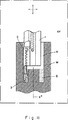
図11は正面溝切り中の加工物内における図2に示された切削工具組立体の配置を図式的に示す基準面XYにおける断面図である。そして、
図12は本発明による切削工具の別の実施例を示す。
好ましい実施例の説明
図1、2、及び3は、本発明による切削工具組立体を示す。図1及び2に見られるように、切削工具組立体は、長手方向軸線X’を有する細長い全体として円筒形の工具シャンク1、自己保持形で割出し可能な切削用インサートであることが好ましい切削用インサート3を保持している実質的に細長いアダプター2、及び一般に4で示されかつアダプター2を工具シャンク1に組み付けるための2個の組付けネジ5と6とを含んだネジ手段を備える。
この切削工具は、内側の機械加工、特に図11に示されるような回転軸線X”を有する加工物Wの比較的深くかつ狭い穴H内における深い環状の溝Gの機械加工に使用するようにされる。作業中、工具シャンクの長手方向軸線X’は回転軸線X”と平行であるか又は一致する。組立体は基準面XY(図11の面)を有し、これは加工物Wの回転軸線X’を通過し、かつこれは工具の平面図と一般に平行である。図2に図式的に示されるように、説明の実施例においては、工具シャンク1の長手方向回転軸線X’並びに切削用インサート3の切れ刃7は基準面XY内にある。しかし、これらを異なった方法で配置することができる。例えば、切れ刃7を基準面の上方に置くことができる。
図1に見られるように、工具シャンク1はその先端9に隣接して工具シャンクの側面に形成されたシャンク保持部分8を持つ。シャンク保持部分8は軸方向に長い長方形の中央突起10及び突起10の両側の軸方向の衝合面12と13を持つ。突起は衝合面12、13とともに工具シャンクの先端9からシャンク保持部分8の後端11まで伸び更に基準面に関して実質的に対称的に配置されかつこれに対して実質的に直角方向に向けられる。シャンク保持部分8は、半径方向に向けられかつ保持部分の後端11に隣接して配置された追加の衝合面15を持つ。図1及び3に見られるように、突起10は突起ベース14及び基準面XYに平行な側壁17と18を持つ。
図1に見られるように、シャンク保持部分8には、突起10を通過する2個の平行なネジ穴22と23とが形成され、これらの軸線は実質的に基準面内に配置されかつ工具シャンクの長手方向軸線X’に垂直である。
図4、5、及び6に見られるように、工具シャンク1には冷却液供給手段(図示せず)と連通する冷却液ダクト配列25(破線で図示)が形成される。冷却液ダクト配列25は、工具シャンクに沿って延びている冷却液用の軸方向の穴26を備え、この穴は、シャンク保持部分8の後端11とネジ穴23との間の区域内でシャンク保持部分内に置かれた冷却液用の横方向の穴27で終わる。横方向の穴27は、横方向に置かれかつ衝合面12及び13で終わる2個の出口部分29を持つ。横方向穴27の出口部分29は、工具シャンク1が説明の実施例におけるように左勝手のアダプターとして使用されるか、又は右勝手アダプターとして使用されるかに依存して交替して使用される。図6に示されるように、冷却液用の横方向の穴27の端部31はプラグ32により栓をされる。
図1及び2に見られるように、アダプター2は円弧状であり、そしてこれには、インサート3を自己把持式に保持するインサート受入れ用のスロット41を有するインサート保持用のブレード部分40、及び工具シャンク1の保持部分8にネジ止めされるアダプター取付け部分42が形成される。アダプター取付け部分42は、インサート保持用部分40からアダプターの末端43まで伸びる。図1には見えないアダプター取付け部分の側面は、シャンク保持部分8と共同作用しかつシャンク保持部分8の形状と合致する形状を持つ。従って、図3に見られるように、アダプター取付け部分には、突起10を受け入れる中央の長い長方形の凹所44、及び凹所44の両側に置かれた衝合面45と46が形成される。図1に見られる突起10及び衝合面12と13と同様に、凹所44及び衝合面45と46は、インサート保持用ブレード部分40からアダプター取付け部分42の末端43まで伸びる。図3に戻って、凹所44は凹所ベース48及び側壁49と50を有し、これら側壁は、突起の側壁17と16との間の距離より僅かに大きな距離の間隔を空けられる。更に、凹所44の深さは突起10の高さより大きい。図4に見られるように、アダプター取付け部分42は追加の衝合面52を有し、これはシャンク保持部分8の追加の衝合面15と衝合する。
図1に示されるように、アダプター取付け部分42には、凹所44を通過する2個の貫通穴53及び54が形成される。貫通穴53及び54の軸線はネジ穴22及び23の軸線と平行である。
説明の実施例においては、貫通穴53と54及びネジ穴22と23は、図7の線VIII-VIII及びVIII'-VIII'に沿った工具の同様な断面を示す図8に見られるものと実質的に同様な形状のものである。見られるように、各貫通穴53、54は好ましくは対称形の皿穴部分55及び把持区域56を有し、この把持区域は皿穴部分のその他の場所よりも穴の縁に近い。貫通穴53及び54の把持区域56は、これら穴の軸線の位置に応じて基準面XYに関して異なった側に置かれる。
図4、5、及び6に見られるように、アダプター取付け部分42にはアダプターの軸方向の冷却液穴57が形成され、この穴は、アダプター端末部分43に近接して配置されかつ冷却液用の横方向穴27の出口部分29と揃えられた流体入口オリフィス58(図6)と、冷却液を切れ刃7の付近に向けるようにインサート保持部分40に近接しかつそのの上方に配置された流体出口オリフィス59(これは図2にも示される)との間を伸びる。
さて、図1に戻ると、各組付け用ネジ5、6は、アダプター取付け部分42の貫通穴53、54にそれぞれ自由に受け入れられるようにされた把持用の頭部60、及びシャンク保持部分8のネジ穴22、23内にねじ込まれるネジ部分61を持つ。把持用の頭部60には、貫通穴53、54の皿穴部分55の傾斜角に相当する傾斜角を有する円錐状の把持用部分63が形成される。
図7及び10を参照し、アダプター2と工具シャンク1との連結方法が説明されるであろう。アダプター取付け部分42がシャンク保持部分8に取り付けられると、突起10は間隙65を残して凹所44内に受け入れられる(図8)。図8に見られるように、貫通穴53及び54はネジ穴22及び23と実質的に揃えられるが、この配列は、貫通穴53及び54の軸線が工具シャンクの長手方向軸線に沿った方向及び基準面に垂直な方向の双方においてそれぞれネジ穴22及び23の軸線に関して僅かに食い違いにされる。即ち、各貫通穴53、54の軸線は、それぞれのネジ穴の軸線よりもインサート保持部分40に近く、インサート保持部分40に近い方に配置された穴53の軸線は基準面の僅か上方に置かれ、そしてアダプター取付け部分42の末端43に近い方に配置された穴54の軸線は基準面の僅か下方に置かれる。
図9及び10を参照し説明すれば、組付けねじ5及び6をネジ穴22及び23内にネジ連結する場合は、手順の如何に拘わらず、衝合面45及び46がシャンク保持部分の衝合面12及び13に当たって押し合う。同時に、図8に見られるように、各ネジ5、6のネジ頭部60の把持部分63は、その把持区域56において、それぞれ貫通穴の皿の部分55に当たりこれと押し合う。揃えられた穴及びその把持区域56のこの特別な相互配置のため、予定位置70a、70bにおける各ネジ5、6の把持部分63と貫通穴の皿の部分55との組合いが生ずる(図7)。一方、予定位置70a及び70bは、穴のアダプターの末端43側の区域に置かれ、これにより確実に、アダプター取付け部分はシャンク保持部分の衝合面15に向かう方向に押され、他方、インサート保持部分に近い方の接触70aの位置が基準面の下方に置かれると同時にアダプターの端末43に近い方の接触70bの位置が基準面の上方に置かれる。組付けネジ5、6と貫通穴53、54との間の接触位置のかかる配置により、アダプターは横方向衝合面12及び13上で僅かに回され、これにより基準面に関して異なった側にある予定位置80a、80bにおける突起の壁面17、18と凹所の壁面49、50との組合いが達成される。こうして、切れ刃7に近い接触域80aは基準面の上方に置かれ(図10)、そして端末43に近い接触域80bは基準面の下方に置かれる(図11)。その結果、把持力が平衡され、アダプターの工具シャンクに対する安定かつ強固な組付けの達成が保証される。
このようにして、本発明は、極めて簡単でかつ使用者に親切な組付け機構を提供する。更に、この組付け機構により、比較的少数の工具組立体構成要素と工具組立体の小型化、比較的大きな製作許容差による簡単な取扱いと比較的容易な製造、信頼性と強固な固定とを確実なものとする工具におけるアダプターの正確かつ再現性のある位置決めが可能である。
上述の金属切削工具組立体における工具シャンクは円筒状のものであるので、組付け手順に含まれる組立体のすべての構成要素、即ち、組付けネジ、突起及び凹所は、これらを工具の基準面の近傍に配置することが特に有利である。これは、直径が小さい工具を、例えば、加工物の深くて狭い穴の中で溝、特に深くて狭い溝の機械加工に使用する場合に特に有利である。
図11は、切削作業中の上述の切削工具を示す。矢印は工具の可能な相対運動の方向を示す。陰影部分は、切れ刃の近くの切削域に工具シャンク及びアダプターを通して冷却液をいかに供給するかを図式的に示す。使用される切削工具、特に比較的大きさの小さなインサート把持手段を有する自己把持式のインサートの上述の構成により、切削域への冷却液の効果的な供給が提供され、従って切削用インサートの冷却及び切削域からのチップの排出が提供され、これは、小直径の深い穴及び/又は溝の機械加工に特に有利である。
切削工具組立体は上述されかつ図示されたものとは異なった性質を有し設計できることに注意すべきである。即ち、図面に示された切削工具は左勝手の工具であるが、同じ工具シャンクを右勝手の工具に使用することができる。図12に示されるように、工具シャンクを円筒状ではなくて長方形断面とすることができる。アダプター及び、特にそのインサート保持用のブレード部分は、これを円弧状でなくて平らにすることができる。
突起をアダプター取付け部分に、凹所を工具のシャンク保持部分に形成することができる。アダプター取付け部分とシャンク保持部分との当たり及び衝合面を、アダプター取付け部分及び工具シャンク保持部分の横方向の面ではなくて凹所及び突起のベース面により構成することができる。凹所及び突起の壁面を平面でなくかつ基準面と平行でなく更に互いに平行でなくすることができる。突起と凹所とを僅かの許容差できつく適合させることがでる。この場合、使用には、ただ1個の組付けネジ、従ってただ1組の揃えられた穴しか必要でなく、アダプター及びシャンク保持部分の貫通穴は両者とも実質的に基準面に配置される。
揃えられた穴及び組付けネジは傾けること、特に工具シャンクの長手方向軸線に関し、及び前記基準面に関して異なった方向に傾けることができる。ネジは異なった直径のものとすることができる。組付け手順中に貫通穴の把持部分を予定位置にするために使われる特徴、即ち、貫通穴の皿もみ部分の把持区域、及び揃えられた穴の軸線間のずれた相互関係は、これを組み合わせてではなく二者択一で使うことができ、更にその他の適切な形式で設計することができる。例えば、上の目的に対して、偏心の固定用カム装置を使用できる。貫通穴の軸線を基準面の両側でなく同じ側に置くことができる。
アダプターの冷却液の穴は、アダプターの全長にわたって長手方向に伸び、かつインサート保持部分に流体出口オリフィスを持つことができる。 Field of the invention The present invention provides a tool shank and releasable thereto for use in various cutting operations such as turning, parting off, grooving in particular, front grooving, centering, etc. The present invention relates to a cutting tool assembly including a replaceable adapter that is assembled and holds a replaceable cutting insert.
Background of the invention In typical cutting tool assemblies of the type described above, the adapter holding the cutting insert is usually attached to the shank holding portion of the elongated tool shank by means of an assembly screw. Adapter mounting portion, and a flat or arcuate insert holding portion projecting outward from the adapter mounting portion, and the size of the protrusion of the insert holding portion determines the cutting depth of the work.
Such cutting tools are disclosed, for example, in US4332513 and 5112164. In these patents, the cutting tool is held on the insert holding part by either means of an exchangeable or elastic gripping arm. The cutting tools of both patents are not suitable for front grooving operations with a relatively large depth because the insert holding part cannot be designed to protrude sufficiently with respect to the arm mounting part due to strength limitations and possible vibration problems.
In the cutting tool assembly disclosed in WO94 / 21408, and in the cutting tool assembly manufactured by Plansee and known as TIZIT Maxilock MSS, the adapter allows the use of a cutting tool for relatively deep grooving operations. It has an insert retention part that protrudes essentially. However, due to the special design and special mounting method of the shank holding part to which the adapter is mounted, this assembly has a large number of components and a planned strict installation procedure.
In all the cutting tool assemblies described above, the assembly requires sufficient lateral dimensions due to both the number and arrangement of assembly screws used to connect the adapter to the tool shank. Therefore, in the case of machining inside the groove in a narrow hole in the work piece, i.e. no cutting tool can be used when it is necessary for the entire adapter to enter the work piece with not only the insert holding part of the adapter but also the shank holding part, Thus, it is believed that to this day, only monolithic tools could be used to date, rather than tool assemblies with replaceable adapters.
Accordingly, it is an object of the present invention to provide a cutting tool having a replaceable adapter that allows for accurate and efficient inner machining of grooves, particularly deep and narrow grooves in small diameter workpieces.
Summary of the invention According to the present invention, an elongated tool shank having a shank retaining portion on the side near the tip, and an insert retaining portion and at least two assemblies for retaining replaceable cutting inserts. A cutting tool assembly comprising a replaceable adapter having an adapter mounting portion releasably secured to a shank holding portion by a screw, the cutting tool assembly having a reference surface substantially passing through a cutting edge of the cutting insert;
A recess is formed in one of the adapter mounting portion and the shank holding portion, and the other is formed with a protrusion that matches the recess and is received therein,
At least two adapter through holes are formed in the adapter mounting portion, and at least two screw holes are formed substantially in alignment with the adapter through holes in the shank holding portion. The holes are oriented in a direction transverse to the rotational axis, pass through the recesses and protrusions, the axis of the through hole is slightly offset with respect to the axis of the respective screw hole, and is closer to the insert holding part than the axis of the screw hole. Closely arranged, each assembly screw is inserted into the screw hole of the respective adapter through hole and shank holding part, and the screw head part received in the through hole and the screw part screwed into the screw hole A cutting tool assembly comprising:
A cutting tool assembly is provided in which the axis of the screw hole is substantially located on the reference surface.
With such a design having mounting screws that lie substantially in the tool reference plane, during the internal cutting operation, all assembly components of the assembly, in particular the mounting screws, are substantially It is placed in an area where the maximum space can be used. As a result, the adapter does not need to have an unduly large lateral dimension, which allows an essential miniaturization of the cutting tool. This is particularly important for deep inside operations where it is desirable that not only the adapter insert retaining portion but also the adapter mounting portion with the shank retaining portion enter a small internal dimension workpiece.
In a preferred embodiment of the invention, the tool assembly has only two mounting screws, one of which is located closer to the insert holding part than the other, and each of the through holes and screw holes. Is placed accordingly.
Preferably, the axis of the through hole arranged closer to the insert holding part is placed slightly above the reference plane when viewed from the side of the tool. Furthermore, it is preferable that the axis of the through hole arranged closer to the end of the adapter is placed slightly below the reference plane. In this case, the size of the recess in the direction perpendicular to the reference plane is larger than the size of the protrusion.
Since the axis of the through hole is arranged on a different side with respect to the reference plane, when the screw is screwed into the screw hole, the adapter mounting portion, and thus the adapter, is slightly turned, so that the wall surface of the recess is scheduled. In contact with the protrusion in position. When viewed from the side, the position closer to the insert holding portion of these is arranged above the reference plane, while the other position closer to the end of the adapter is preferably located below the reference plane, This ensures a desired distribution of forces during the cutting operation.
Preferably, the axes of these holes are substantially perpendicular to the longitudinal axis of relative rotation of the workpiece with respect to the tool. However, they can be tilted in the same or different directions with respect to the longitudinal axis.
In a preferred embodiment of the invention, the tool shank is generally elongated and cylindrical and the longitudinal axis of the tool shank is in the reference plane. Thus, the mounting screws of this tool according to the invention are located in the region where the volume of material of the assembly is maximum, so that the screws do not require an unduly large lateral dimension of the adapter. This allows a further substantial miniaturization of the cutting tool, which is particularly advantageous for the above-mentioned types of inner cutting operations. Furthermore, due to the symmetrical design of the shank holding part with respect to the reference plane, the same shank can be used for both the right hand adapter and the left hand adapter.
Preferably, the adapter is substantially arcuate and has a dimension that does not exceed the corresponding dimension of the cylindrical tool shank in a direction perpendicular to the reference plane, so that the cutting tool is a narrow hole in the workpiece. Suitable for inside machining inside. The design according to the invention allows the cutting tool to enter a narrow hole that is considerably deeper than the normal depth despite the presence of the adapter.
Preferably, between the fluid inlet orifice located near the adapter end portion and the fluid outlet orifice located at the tip of the adapter mounting portion above the insert holding portion to direct the coolant near the cutting edge. An adapter coolant hole is formed in the adapter mounting portion extending substantially along the length of the adapter. Preferably, the fluid inlet orifice is connected to the coolant duct arrangement of the tool shank and is in communication with the coolant supply means. The coolant duct arrangement of the tool shank preferably extends along the tool shank and is placed in the tool shank holding part in the area between the rear end of the holding part and at least one of the screw holes. End with a horizontal hole for liquid. The transverse hole for the coolant has at least one outlet portion aligned with the fluid inlet orifice of the adapter.
The transverse hole for the coolant preferably has two outlet parts arranged on either side of the reference plane of the tool, which two outlet parts are used by the tool shank in a left-handed manner. Either one is used depending on whether the right hand is used.
[Brief description of the drawings]
FIG. 1 is an exploded isometric view of a metal cutting tool assembly according to the present invention.
FIG. 2 is an isometric view of the cutting tool shown in FIG.
FIG. 3 is a front view of the cutting tool shown in FIG.
FIG. 4 is a side view of the cutting tool shown in FIG.
FIG. 5 is a plan view of the cutting tool shown in FIG.
6 is a cross-sectional view of the cutting tool shown in FIG. 2 taken along line VI-VI.
FIG. 7 is a side view showing the attachment mechanism of the cutting tool shown in FIG.
FIG. 8 is a cross-sectional view taken along lines VIII-VIII and VIII′-VIII ′ of the cutting tool obtained in a state before the final stage of attachment of the cutting tool shown in FIG.
9 is a cross-sectional view of the cutting tool assembly shown in FIG. 7 taken along line IX-IX.
10 is a cross-sectional view of the cutting tool assembly shown in FIG. 7 along line XX.
FIG. 11 is a cross-sectional view of the reference plane XY schematically showing the arrangement of the cutting tool assembly shown in FIG. 2 in the workpiece during front grooving. And
FIG. 12 shows another embodiment of the cutting tool according to the present invention.
Description <br/> diagram of the
This cutting tool is used for internal machining, in particular for machining deep annular grooves G in a relatively deep and narrow hole H of a workpiece W having a rotation axis X ″ as shown in FIG. In operation, the longitudinal axis X ′ of the tool shank is parallel or coincides with the rotational axis X ″. The assembly has a reference plane XY (the plane of FIG. 11), which passes through the rotation axis X ′ of the workpiece W, and is generally parallel to the plan view of the tool. As schematically shown in FIG. 2, in the embodiment described, the longitudinal axis of rotation X ′ of the tool shank 1 and the
As can be seen in FIG. 1, the tool shank 1 has a
As can be seen in FIG. 1, the
As can be seen in FIGS. 4, 5 and 6, the tool shank 1 is formed with a coolant duct array 25 (shown in broken lines) communicating with coolant supply means (not shown). The
As seen in FIGS. 1 and 2, the
As shown in FIG. 1, the
In the illustrated embodiment, the through
As seen in FIGS. 4, 5 and 6, the
Now, referring back to FIG. 1, each mounting
With reference to FIGS. 7 and 10, the method of connecting the
Referring to FIGS. 9 and 10, when the assembly screws 5 and 6 are screwed into the screw holes 22 and 23, the abutting
In this way, the present invention provides a very simple and user friendly assembly mechanism. In addition, this assembly mechanism allows a relatively small number of tool assembly components and tool assemblies to be miniaturized, simple handling with relatively large manufacturing tolerances, relatively easy manufacturing, reliability and strong fixation. Accurate and reproducible positioning of the adapter in a reliable tool is possible.
Since the tool shank in the metal cutting tool assembly described above is cylindrical, all components of the assembly included in the assembly procedure, i.e. assembly screws, protrusions and recesses, are referred to as the tool reference. It is particularly advantageous to arrange it in the vicinity of the surface. This is particularly advantageous when a tool with a small diameter is used, for example, for machining a groove in a deep and narrow hole in the workpiece, in particular a deep and narrow groove.
FIG. 11 shows the above-described cutting tool during a cutting operation. The arrows indicate the direction of possible relative movement of the tool. The shaded portion schematically shows how coolant is supplied through the tool shank and adapter to the cutting area near the cutting edge. The above-described configuration of the cutting tool used, in particular a self-gripping insert with a relatively small insert gripping means, provides an effective supply of coolant to the cutting area and thus cooling of the cutting insert And the discharge of chips from the cutting area is provided, which is particularly advantageous for machining small diameter deep holes and / or grooves.
It should be noted that the cutting tool assembly can be designed with different properties than those described and illustrated above. That is, the cutting tool shown in the drawing is a left-hand tool, but the same tool shank can be used for a right-hand tool. As shown in FIG. 12, the tool shank can be rectangular in cross section rather than cylindrical. The adapter and in particular the blade part for holding its insert can be flat rather than arcuate.
A protrusion can be formed in the adapter mounting portion and a recess can be formed in the shank holding portion of the tool. The abutting and abutting surfaces of the adapter mounting portion and the shank holding portion can be constituted by the recess and the base surface of the protrusion, instead of the lateral surface of the adapter mounting portion and the tool shank holding portion. The wall surfaces of the recess and the protrusion can be made non-planar, not parallel to the reference plane, and not parallel to each other. The protrusions and recesses can be fitted with a slight tolerance. In this case, only one mounting screw, and thus only one set of aligned holes, is required for use, and both the adapter and the through hole of the shank holding portion are substantially located on the reference plane.
The aligned holes and assembly screws can be tilted, in particular with respect to the longitudinal axis of the tool shank and in different directions with respect to the reference plane. The screws can be of different diameters. The features used to position the through-hole gripping portion during the assembly procedure, i.e., the gripping area of the countersunk portion of the through-hole and the misalignment between the aligned hole axes, are It can be used in an alternative rather than a combination, and can be designed in other suitable forms. For example, an eccentric locking cam device can be used for the above purpose. The axis of the through hole can be placed on the same side instead of on both sides of the reference plane.
The adapter coolant holes can extend longitudinally over the length of the adapter and have a fluid outlet orifice in the insert retaining portion.
Claims (7)
アダプター取付け部分とシャンク保持部分の一方に凹所が形成されており、他方にはこの凹所と一致しかつその中に受け入れられる突起が形成されており、
前記アダプター取付け部分には少なくも2個のアダプター貫通穴が形成されており、更に前記シャンク保持部分には少なくも2個のネジ穴がそれぞれアダプター貫通穴と実質的に整合して形成され、これら少なくも2個のアダプター貫通穴及び少なくも2個のネジ穴は前記長手方向軸線Xを横切る方向に向けられ、且つ実質的に基準面に沿って凹所と突起とを通過し、貫通穴の軸線はそれぞれのネジ穴の軸線に関して食い違いにされかつネジ穴の軸線よりもインサート保持部分に近く配置され、各組付けネジはそれぞれのアダプター貫通穴とシャンク保持部分のネジ穴の中に差し込まれ、前記貫通穴の中に受け入れられるネジ頭部部分と前記ネジ穴の中にねじ込まれるネジ部分とを有する切削工具組立体において、
工具シャンクが細長い円筒形であり、そしてアダプターが実質的に円弧状であり且つ円筒状の工具シャンクの対応寸法を越えない横方向寸法を有することを特徴とする切削工具組立体。With an elongated tool shank having a shank holding portion on the side near the tip and extending along the longitudinal axis X, and an insert holding portion and at least two assembly screws for holding a replaceable cutting insert includes a replaceable adapter having an adapter mounting portion releasably secured to the shank holding portion, said cutting edge of the cutting insert have a reference plane that passes substantially through the longitudinal axis of the tool shank X A cutting tool assembly in the reference plane ,
A recess is formed in one of the adapter mounting portion and the shank holding portion, and the other is formed with a protrusion that matches the recess and is received therein,
At least two adapter through holes are formed in the adapter mounting portion, and at least two screw holes are formed substantially in alignment with the adapter through holes in the shank holding portion. At least two adapter through holes and at least two screw holes are oriented in a direction transverse to the longitudinal axis X and substantially pass through the recesses and protrusions along the reference plane. The axis is staggered with respect to the axis of each screw hole and is positioned closer to the insert holding part than the axis of the screw hole, and each assembly screw is inserted into the screw hole of the respective adapter through hole and shank holding part, A cutting tool assembly having a screw head portion received in the through hole and a screw portion screwed into the screw hole;
A cutting tool assembly characterized in that the tool shank is elongated and cylindrical and the adapter is substantially arcuate and has a transverse dimension that does not exceed the corresponding dimension of the cylindrical tool shank.
Applications Claiming Priority (3)
| Application Number | Priority Date | Filing Date | Title |
|---|---|---|---|
| IL11137094A IL111370A (en) | 1994-10-23 | 1994-10-23 | Cutting tool assembly having an exchangeable adaptor |
| IL111370 | 1994-10-23 | ||
| PCT/US1995/014394 WO1996012592A1 (en) | 1994-10-23 | 1995-10-20 | Cutting tool assembly having an exchangeable adaptor |
Publications (2)
| Publication Number | Publication Date |
|---|---|
| JPH09510149A JPH09510149A (en) | 1997-10-14 |
| JP3856339B2 true JP3856339B2 (en) | 2006-12-13 |
Family
ID=11066683
Family Applications (1)
| Application Number | Title | Priority Date | Filing Date |
|---|---|---|---|
| JP51415396A Expired - Fee Related JP3856339B2 (en) | 1994-10-23 | 1995-10-20 | Cutting tool assembly with replaceable adapter |
Country Status (19)
| Country | Link |
|---|---|
| US (1) | US5709508A (en) |
| EP (1) | EP0741634B1 (en) |
| JP (1) | JP3856339B2 (en) |
| KR (1) | KR100388767B1 (en) |
| CN (1) | CN1140429A (en) |
| AT (1) | ATE202028T1 (en) |
| AU (1) | AU698897B2 (en) |
| BG (1) | BG100660A (en) |
| BR (1) | BR9506424A (en) |
| CA (1) | CA2179509A1 (en) |
| CZ (1) | CZ174896A3 (en) |
| DE (2) | DE741634T1 (en) |
| ES (1) | ES2095198T1 (en) |
| GE (1) | GEP19981348B (en) |
| HU (1) | HUT76539A (en) |
| IL (1) | IL111370A (en) |
| PL (1) | PL315152A1 (en) |
| SK (1) | SK80696A3 (en) |
| WO (1) | WO1996012592A1 (en) |
Families Citing this family (54)
| Publication number | Priority date | Publication date | Assignee | Title |
|---|---|---|---|---|
| AU709407B2 (en) * | 1996-10-17 | 1999-08-26 | Karl Ziegler | Cutting tool assembly |
| AUPO304396A0 (en) | 1996-10-17 | 1996-11-14 | Ziegler, Karl | Cutting assembly |
| IL127738A (en) * | 1998-12-25 | 2001-08-08 | Iscar Ltd | Cutting tool assembly |
| US6186704B1 (en) | 1999-03-04 | 2001-02-13 | Kennametal Inc. | Toolholder with detachable blade |
| DE10331077B3 (en) * | 2003-07-09 | 2005-02-17 | Ernst Graf | Turning tool holder |
| JP4639862B2 (en) | 2004-03-26 | 2011-02-23 | 三菱マテリアル株式会社 | Claw mechanism for throw-away tip |
| FR2872723B1 (en) * | 2004-07-12 | 2006-09-08 | Seco Tools Ab | MACHINING TOOL, IN PARTICULAR FOR FORMING A CONICAL SURFACE |
| US7240593B2 (en) * | 2005-04-19 | 2007-07-10 | Roger Little | Miniature cutting insert holder |
| DE102005024746A1 (en) * | 2005-05-31 | 2006-12-07 | Hartmetall-Werkzeugfabrik Paul Horn Gmbh | Toolholder system |
| JP4867661B2 (en) * | 2006-03-02 | 2012-02-01 | 三菱マテリアル株式会社 | Insert detachable cutting tool |
| JP5028883B2 (en) * | 2006-06-30 | 2012-09-19 | 三菱マテリアル株式会社 | Insert detachable cutting tool |
| ITTO20060724A1 (en) * | 2006-10-09 | 2008-04-10 | Alenia Aeronautica Spa | TOOL AND MILLING METHOD, IN PARTICULAR FOR THE MILLING OF COMPOSITE MATERIALS |
| SE530581C2 (en) * | 2006-11-28 | 2008-07-08 | Sandvik Intellectual Property | Chip separation tool and basic body comprising two channels for a fluid |
| SE530579C2 (en) * | 2006-11-28 | 2008-07-08 | Sandvik Intellectual Property | Tools and basic body for multi-channel chip separation machining |
| US8727673B2 (en) | 2007-01-18 | 2014-05-20 | Kennametal Inc. | Cutting insert with internal coolant delivery and surface feature for enhanced coolant flow |
| US9101985B2 (en) * | 2007-01-18 | 2015-08-11 | Kennametal Inc. | Cutting insert assembly and components thereof |
| US8454274B2 (en) | 2007-01-18 | 2013-06-04 | Kennametal Inc. | Cutting inserts |
| KR100901472B1 (en) | 2007-07-18 | 2009-06-08 | 대구텍 주식회사 | Modular tool assembly |
| IL185047A (en) * | 2007-08-05 | 2011-09-27 | Iscar Ltd | Cutting tool |
| JP5115148B2 (en) * | 2007-10-30 | 2013-01-09 | 三菱マテリアル株式会社 | Insert detachable cutting tool head member and insert detachable cutting tool |
| JP5040591B2 (en) * | 2007-10-30 | 2012-10-03 | 三菱マテリアル株式会社 | Insert detachable cutting tool head member and insert detachable cutting tool |
| JP5309894B2 (en) | 2008-10-29 | 2013-10-09 | 三菱マテリアル株式会社 | Insert detachable cutting tool |
| IL198053A (en) * | 2009-04-07 | 2012-03-29 | Iscar Ltd | Cutting tool and cutting insert therefor |
| JP5589401B2 (en) * | 2010-01-22 | 2014-09-17 | 三菱マテリアル株式会社 | Replaceable cutting edge grooving tool and end face grooving method |
| JP5564958B2 (en) * | 2010-01-22 | 2014-08-06 | 三菱マテリアル株式会社 | Replaceable cutting edge grooving tool and end face grooving method |
| JP5560748B2 (en) * | 2010-02-05 | 2014-07-30 | 三菱マテリアル株式会社 | Exchangeable grooving tool and peripheral grooving method |
| JP5678431B2 (en) * | 2010-02-05 | 2015-03-04 | 三菱マテリアル株式会社 | Exchangeable grooving tool and peripheral grooving method |
| ES2757552T3 (en) | 2010-08-04 | 2020-04-29 | Ceram Gmbh | Cutting plate for cutting tool for drilling and turning |
| US8827599B2 (en) | 2010-09-02 | 2014-09-09 | Kennametal Inc. | Cutting insert assembly and components thereof |
| US8388268B2 (en) * | 2011-03-07 | 2013-03-05 | Kennametal Inc. | Cutting assembly |
| DE202011101852U1 (en) * | 2011-06-14 | 2012-09-19 | Hartmetall-Werkzeugfabrik Paul Horn Gmbh | cutter |
| US8827598B2 (en) | 2011-11-22 | 2014-09-09 | Kennametal Inc. | Cutting assembly with enhanced coolant delivery |
| DE112013001334B4 (en) * | 2012-03-06 | 2022-11-03 | Iscar Ltd. | cutting tool assembly |
| WO2014001447A1 (en) * | 2012-06-28 | 2014-01-03 | Ceramtec Gmbh | Tool for machining |
| US9050658B2 (en) * | 2012-07-24 | 2015-06-09 | Iscar, Ltd. | Cutting insert with bottom stopper surface between bottom abutment surfaces and cutting tool therefor |
| SE536741C2 (en) * | 2012-11-08 | 2014-07-08 | Sandvik Intellectual Property | Cutting tools and knitting blades for this |
| EP2745963B2 (en) | 2012-12-19 | 2021-03-17 | Seco Tools Ab | Coupling for a cooling system in a cutting tool |
| US9931699B2 (en) * | 2013-10-18 | 2018-04-03 | Ngk Spark Plug Co., Ltd. | Cutting tool holder and cutting tool |
| EP2873477A3 (en) * | 2013-11-14 | 2015-12-23 | Sandvik Tooling France | Cartridge for a grooving tool holder, corresponding grooving tool holder, kit and assembly thereof |
| JP6032370B2 (en) * | 2014-01-14 | 2016-11-24 | 株式会社タンガロイ | Tool blocks and cutting tools |
| CN103878451B (en) * | 2014-03-14 | 2017-02-01 | 中山中炬精工机械有限公司 | Shockproof threaded tool rod |
| US9702385B2 (en) * | 2014-05-15 | 2017-07-11 | Iscar, Ltd. | Machine tool assembly configured for swift disassembly |
| JP2017121668A (en) * | 2014-05-23 | 2017-07-13 | 株式会社タンガロイ | Plate-like member of cutting tool, tool block, and cutting tool |
| ES2796260T3 (en) * | 2014-11-18 | 2020-11-26 | Walter Ag | Perforator Blade and Slotting and Cutting Tool |
| CN104772516A (en) * | 2015-04-07 | 2015-07-15 | 南京益精机械刀具制造有限公司 | Conveniently-used efficient lathe tool |
| DE112018004430T5 (en) * | 2017-10-06 | 2020-05-20 | Kyocera Corporation | CUTTING TOOL AND METHOD FOR PRODUCING A MACHINED PRODUCT |
| CA3083206A1 (en) * | 2017-11-30 | 2019-06-06 | Iscar Ltd. | Modular turning tool having a replaceable adaptor |
| CN107803536B (en) * | 2017-12-01 | 2023-08-25 | 哈电集团(秦皇岛)重型装备有限公司 | Nuclear power container connecting pipe inner groove machining tool and machining method thereof |
| CN109128231A (en) * | 2018-10-19 | 2019-01-04 | 中国航发航空科技股份有限公司 | A kind of lathe processing tool bit of aero-engine compressor multistage leaf dish weld assembly small space |
| CN111604511A (en) * | 2020-07-01 | 2020-09-01 | 张晓刚 | A multi-level stepped deep groove grooving tool |
| US11897038B2 (en) * | 2020-09-30 | 2024-02-13 | Iscar, Ltd. | Curved face grooving blade and face grooving holder therefor |
| KR20230091931A (en) * | 2020-10-20 | 2023-06-23 | 이스카 엘티디. | Coolant conduits for cutting tool assemblies |
| JP7223298B2 (en) * | 2021-07-20 | 2023-02-16 | 株式会社タンガロイ | Shank and cutting tool with same |
| US20230356311A1 (en) * | 2022-05-03 | 2023-11-09 | Iscar, Ltd. | Rotationally asymmetric double-ended grooving cutting insert, insert holder and cutting tool |
Family Cites Families (10)
| Publication number | Priority date | Publication date | Assignee | Title |
|---|---|---|---|---|
| US3686729A (en) * | 1971-05-05 | 1972-08-29 | Warner Swasey Co | Cutoff or grooving tool and holder therefor |
| AU464694B2 (en) * | 1972-09-27 | 1975-09-04 | Stratco Metal Proprietary Limited | Gutter suspension means |
| US4332513A (en) * | 1980-07-24 | 1982-06-01 | General Electric Company | Face grooving tool |
| US4695208A (en) * | 1985-11-14 | 1987-09-22 | Yankoff Gerald K | Tool holder |
| CH667407A5 (en) * | 1986-03-27 | 1988-10-14 | Stellram Sa | STRAWBERRY WITH REMOVABLE CUTTING INSERTS. |
| US4744703A (en) * | 1987-02-10 | 1988-05-17 | Manchester Tool Company | Rotary cutter for slotting or cut-off |
| AT388125B (en) * | 1987-07-22 | 1989-05-10 | Plansee Tizit Gmbh | LANDING TOOL |
| IL84171A (en) * | 1987-10-14 | 1990-09-17 | Iscar Ltd | Cutting insert and tool holder therefor |
| IL91574A (en) * | 1989-09-08 | 1992-02-16 | Iscar Ltd | Cutting tool system having an exchangeable adaptor |
| US5112163A (en) * | 1991-09-20 | 1992-05-12 | Thomas Veilleux | Variable tool bit holder |
-
1994
- 1994-10-23 IL IL11137094A patent/IL111370A/en not_active IP Right Cessation
-
1995
- 1995-10-20 AU AU42315/96A patent/AU698897B2/en not_active Ceased
- 1995-10-20 CA CA002179509A patent/CA2179509A1/en not_active Abandoned
- 1995-10-20 AT AT95940631T patent/ATE202028T1/en not_active IP Right Cessation
- 1995-10-20 JP JP51415396A patent/JP3856339B2/en not_active Expired - Fee Related
- 1995-10-20 SK SK806-96A patent/SK80696A3/en unknown
- 1995-10-20 CZ CZ961748A patent/CZ174896A3/en unknown
- 1995-10-20 GE GEAP19953240A patent/GEP19981348B/en unknown
- 1995-10-20 CN CN95191487.1A patent/CN1140429A/en active Pending
- 1995-10-20 PL PL95315152A patent/PL315152A1/en unknown
- 1995-10-20 BR BR9506424A patent/BR9506424A/en not_active Application Discontinuation
- 1995-10-20 DE DE0741634T patent/DE741634T1/en active Pending
- 1995-10-20 ES ES95940631T patent/ES2095198T1/en active Pending
- 1995-10-20 KR KR1019960703368A patent/KR100388767B1/en not_active IP Right Cessation
- 1995-10-20 DE DE69521293T patent/DE69521293T2/en not_active Expired - Lifetime
- 1995-10-20 WO PCT/US1995/014394 patent/WO1996012592A1/en active IP Right Grant
- 1995-10-20 HU HU9601633A patent/HUT76539A/en unknown
- 1995-10-20 US US08/546,463 patent/US5709508A/en not_active Expired - Lifetime
- 1995-10-20 EP EP95940631A patent/EP0741634B1/en not_active Expired - Lifetime
-
1996
- 1996-06-17 BG BG100660A patent/BG100660A/en unknown
Also Published As
| Publication number | Publication date |
|---|---|
| WO1996012592A1 (en) | 1996-05-02 |
| HUT76539A (en) | 1997-09-29 |
| EP0741634A4 (en) | 1998-01-28 |
| IL111370A (en) | 1998-08-16 |
| CZ174896A3 (en) | 1997-09-17 |
| US5709508A (en) | 1998-01-20 |
| SK80696A3 (en) | 1997-08-06 |
| KR100388767B1 (en) | 2003-09-26 |
| BG100660A (en) | 1997-03-31 |
| ES2095198T1 (en) | 1997-02-16 |
| GEP19981348B (en) | 1998-08-25 |
| HU9601633D0 (en) | 1996-08-28 |
| PL315152A1 (en) | 1996-10-14 |
| CN1140429A (en) | 1997-01-15 |
| ATE202028T1 (en) | 2001-06-15 |
| AU4231596A (en) | 1996-05-15 |
| AU698897B2 (en) | 1998-11-12 |
| DE69521293D1 (en) | 2001-07-19 |
| EP0741634A1 (en) | 1996-11-13 |
| CA2179509A1 (en) | 1996-05-02 |
| DE741634T1 (en) | 1997-05-15 |
| DE69521293T2 (en) | 2001-10-11 |
| BR9506424A (en) | 1997-09-09 |
| EP0741634B1 (en) | 2001-06-13 |
| IL111370A0 (en) | 1994-12-29 |
| JPH09510149A (en) | 1997-10-14 |
Similar Documents
| Publication | Publication Date | Title |
|---|---|---|
| JP3856339B2 (en) | Cutting tool assembly with replaceable adapter | |
| JP3835865B2 (en) | Cutting tool assembly | |
| US5873684A (en) | Thread mill having multiple thread cutters | |
| AU768247B2 (en) | Toolholder with detachable blade | |
| CN107708900B (en) | Cutting tool with nozzle with internal coolant channel | |
| EP0822877B1 (en) | Rotatable type machine tool | |
| KR101054783B1 (en) | Cutting tool with split insert | |
| WO2010050228A1 (en) | Cutting tool configured so that insert can be removably mounted thereto | |
| EP2498937B1 (en) | Cutting tool assembly | |
| US4684298A (en) | Drill | |
| EP0213847A2 (en) | A metal cutting tool | |
| WO2023223308A1 (en) | Tool holder having a cylindrical fixation bore extending rearwardly from a front fixation surface and a fastening bore intersecting the front fixation surface | |
| WO2009157606A1 (en) | Adjustable double head cutting tool | |
| CA2219291C (en) | Rotatable type machine tool | |
| JPH10118821A (en) | Cutter |
Legal Events
| Date | Code | Title | Description |
|---|---|---|---|
| A131 | Notification of reasons for refusal |
Free format text: JAPANESE INTERMEDIATE CODE: A131 Effective date: 20050104 |
|
| A521 | Request for written amendment filed |
Free format text: JAPANESE INTERMEDIATE CODE: A523 Effective date: 20050404 |
|
| A131 | Notification of reasons for refusal |
Free format text: JAPANESE INTERMEDIATE CODE: A131 Effective date: 20060110 |
|
| A521 | Request for written amendment filed |
Free format text: JAPANESE INTERMEDIATE CODE: A523 Effective date: 20060410 |
|
| TRDD | Decision of grant or rejection written | ||
| A01 | Written decision to grant a patent or to grant a registration (utility model) |
Free format text: JAPANESE INTERMEDIATE CODE: A01 Effective date: 20060905 |
|
| A61 | First payment of annual fees (during grant procedure) |
Free format text: JAPANESE INTERMEDIATE CODE: A61 Effective date: 20060908 |
|
| R150 | Certificate of patent or registration of utility model |
Free format text: JAPANESE INTERMEDIATE CODE: R150 |
|
| FPAY | Renewal fee payment (event date is renewal date of database) |
Free format text: PAYMENT UNTIL: 20100922 Year of fee payment: 4 |
|
| FPAY | Renewal fee payment (event date is renewal date of database) |
Free format text: PAYMENT UNTIL: 20110922 Year of fee payment: 5 |
|
| FPAY | Renewal fee payment (event date is renewal date of database) |
Free format text: PAYMENT UNTIL: 20120922 Year of fee payment: 6 |
|
| FPAY | Renewal fee payment (event date is renewal date of database) |
Free format text: PAYMENT UNTIL: 20130922 Year of fee payment: 7 |
|
| R250 | Receipt of annual fees |
Free format text: JAPANESE INTERMEDIATE CODE: R250 |
|
| R250 | Receipt of annual fees |
Free format text: JAPANESE INTERMEDIATE CODE: R250 |
|
| LAPS | Cancellation because of no payment of annual fees |