JP3854737B2 - Data processing apparatus and method, and data processing system - Google Patents
Data processing apparatus and method, and data processing system Download PDFInfo
- Publication number
- JP3854737B2 JP3854737B2 JP32563598A JP32563598A JP3854737B2 JP 3854737 B2 JP3854737 B2 JP 3854737B2 JP 32563598 A JP32563598 A JP 32563598A JP 32563598 A JP32563598 A JP 32563598A JP 3854737 B2 JP3854737 B2 JP 3854737B2
- Authority
- JP
- Japan
- Prior art keywords
- objects
- profile
- level
- image data
- decoder
- Prior art date
- Legal status (The legal status is an assumption and is not a legal conclusion. Google has not performed a legal analysis and makes no representation as to the accuracy of the status listed.)
- Expired - Fee Related
Links
Images


Landscapes
- Compression Of Band Width Or Redundancy In Fax (AREA)
- Image Processing (AREA)
- Color Television Systems (AREA)
- Compression Or Coding Systems Of Tv Signals (AREA)
Description
【0001】
【発明の属する技術分野】
本発明は、符号化された複数の画像情報により1つの画像を構成するデータ列を処理するデータ処理装置及びその方法、及びデータ処理システムに関する。
【0002】
【従来の技術】
近年、動画像の新しい符号化方式として、MPEG4(Moving Picture Experts Group Phase4)規格の標準化が進められている。従来のMPEG2規格に代表される動画像の符号化方式においては、フレームあるいはフィールドを単位とした符号化を行なっていたが、動画像の映像や音声を構成するコンテンツ(人物や建物,声,音,背景等)の再利用や編集を実現するために、MPEG4規格では映像データやオーディオ・データをオブジェクト(物体)として扱うことを特徴とする。さらに、映像データに含まれる物体も独立して符号化され、それぞれもオブジェクトとして扱うことができる。
【0003】
図17にMPEG4規格に基づく符号化器の機能ブロック図を示し、図18に該符号化器による符号化データを復号する復号器の機能ブロック図を示す。図17において、入力された画像データはオブジェクト定義器1001によって各オブジェクトに分割され、分割されたオブジェクト毎に最適な符号化を行なう、それぞれのオブジェクト符号化器1002〜1004によって符号化する。また、各オブジェクトを復号側で配置するための情報を、配置情報符号化器1011で符号化する。こうして得られた符号化データを、多重化器1005によって多重化して1つの符号化データとして出力する。
【0004】
該符号化データが図18に示す復号器に入力されると、まず分離器1006によって多重化を解かれ、各オブジェクトの符号化データを得る。得られた符号化データは各オブジェクトに対応した復号器1007〜1009によって復号される。同時に、配置情報復号器1012は各オブジェクトの配置情報を復号する。オブジェクト復号器1007〜1009の出力は、オブジェクト配置情報に従って合成器1010によって合成され、画像として表示される。
【0005】
このようにMPEG4規格によれば、動画像内のオブジェクトを個別に扱うことで、復号側ではさまざまなオブジェクトを自由に配置することができる。また、放送やコンテンツ作成会社等においても、事前にオブジェクトの符号化データを生成しておくことにより、有限なコンテンツから非常に多くの動画像データを生成することが可能になった。
【0006】
【発明が解決しようとする課題】
しかしながら、上述したようにMPEG4規格の符号化方式においては、不特定数のオブジェクトを扱うため、特に復号側では、全てのオブジェクトの復号に対応するのに十分な復号手段の数を確定することができず、従って、装置やシステムを構築するのが非常に困難であった。
【0007】
そのため、標準化されたMPEG4規格においては、プロファイル及びレベルの概念を規定し、符号化データや符号化器/復号器の設計にあたって仕様を決定することができるように、プロファイル及びレベルからなる符号化仕様として、オブジェクト数やビットレートの上限値を設けている。図20に、プロファイル・レベル毎の各要件の上限を規定するプロファイル表の一例を示す。
【0008】
図20のプロファイル表に示されるようにMPEG4規格においては、プロファイルに応じて符号化に使用する手段(ツール)の組み合わせが異なり、さらにレベルにより、扱う画像の符号化データの量が段階的に分けられている。ここで、扱えるオブジェクト数の最大値とビットレートの最大値はいずれも該符号化仕様における上限を表すものであり、それ以下の値であれば、該符号化仕様に含まれる。例えば、Coreプロファイルで使用可能なツールを用い、オブジェクト数が6個で、300kbpsで符号化するのであれば、該符号化データ(符号化器)はレベル2に相当する。
【0009】
ここで、MPEG4符号化データのビットストリーム例を図19に示す。上述したプロファイルとレベルは、ビットストリームの中のprofile_and_level_indication(図中PLI)という符号で表される。MPEG4においては、オブジェクトの配置情報をシステム記述言語で表して符号化しており、便宜上、この情報を先頭に記載する。実際には、適宜ほかの符号化結果とともに多重化されている。
【0010】
MPEG4符号化データは、符号化効率の向上、及び編集操作性の向上の観点から階層化されている。図19に示すように、動画像の符号化データの先頭には、識別のためのvisual_object_sequence_start_code(図中VOSSC)があり、それに各ビジュアルオブジェクトの符号化データが続き、最後に、符号化データの後端を示すvisual_object_sequence_end_code(図中VOSEC)がある。ここでビジュアルオブジェクトとしては、撮影された動画像のほかに、CGデータ等も定義される。
【0011】
ビジュアルオブジェクトの詳細としては、先頭に識別のためのvisual_object_start_code(図中Visual Object SC)があり、続いて前述のPLIがある。それ以降、ビジュアルオブジェクトの情報を表す符号であるis_visual_object_identifier(図中IVOI),visual_object_verid(図中VOVID),visual_object_priority(図中VOPRI),visual_object_type(図中VOTYPE)などが続き、ビジュアルオブジェクトのヘッダ情報を構成している。ここで、visual_object_type(VOTYPE)は例えば、該画像が撮像された動画像である場合は"0001"であり、これに続いて動画像の符号化データの魂を表すビデオオブジェクト(VO)データが続く。
【0012】
ビデオオブジェクトデータは、それぞれのオブジェクトを表す符号化データであり、スケーラビリティを実現するためのビデオオブジェクトレイヤデータ(VOL)と、動画像の1フレームに相当するビデオオブジェクトプレーンデータ(VOP)がある。それぞれのヘッダ部分には、サイズを表す符号video_object_layer_width(図中VOL_width),video_object_layer_height(図中VOL_height)及びvideo_object_plane_width(図中VOP_width),video_object_plane_height(図中VOP_height)を備える。
【0013】
このビットストリームを復号する復号器においては、PLI符号を参照することによって、復号が可能か否かを判定することができる。即ち、以下のような場合には復号が行なえない。
【0014】
例えば、Coreプロファイル・レベル1の復号器では、Coreプロファイル・レベル2のデータであって、ビットレート等の上限を超える符号化データは復号できない。
【0015】
また、Simpleプロファイル・レベル1であって、オブジェクトを4つ含む画像の符号化データを2つ合成することにより、Simpleプロファイル・レベル2の符号化データを生成することが考えられる。しかしながらこの場合、レベル2のオブジェクト最大数は4であるため、MPEG4のいずれのプロファイルやレベルにも所属しない符号化データが生成されてしまうことになる。従って、このような符号化データを復号することはできない。
【0016】
また、例えばSimpleプロファイル48kbpsと8kbpsの2つの符号化データ(それぞれのオブジェクト数は2)を多重化して新しいビットストリームを生成すると、そのビットレートが64kbpsに収まらない場合がある。このような場合にはレベルを2にする必要があり、即ち、レベル1の復号器では復号できない。
【0017】
以上のように、復号器の符号化仕様(プロファイル及びレベル)が、符号化データの符号化仕様(プロファイル及びレベル)を十分に包含できない場合には、該符号化データを復号することはできなかった。
【0018】
本発明は上述した問題を解決するためになされたものであり、複数の画像情報(オブジェクト)毎に符号化された符号化データを、任意の符号化仕様の復号器で最適に復号可能とするデータ処理装置及びその方法、及びデータ処理システムを提供することを目的とする。
【0019】
また、符号化データに含まれるオブジェクト数を調整可能なデータ処理装置及びその方法、及びデータ処理システムを提供することを目的とする。
【0020】
【課題を解決するための手段】
上記目的を達成するための一手段として、本発明のデータ処理装置は以下の構成を備える。
【0021】
即ち、符号化された複数のオブジェクトを含む符号化画像データを処理するデータ処理装置であって、前記符号化画像データ内に含まれる該オブジェクトから符号器のプロファイル及びレベルを抽出する抽出手段と、前記符号化画像データを復号する復号器から該復号器のプロファイル及びレベルを取得する取得手段と、前記符号器のプロファイル及びレベルと前記復号器のプロファイル及びレベルとを比較し、前記復号器のプロファイル及びレベルが前記符号器のプロファイル及びレベルよりも下位の場合に、前記符号化画像データ中のオブジェクトの数を検出し、検出されたオブジェクトの数が前記復号器のプロファイル及びレベルから得られる該復号器で復号可能なオブジェクト数よりも多い場合に、前記符号化画像データ中のオブジェクトの数を変更する変更手段とを有することを特徴とする。
【0023】
また、上記目的を達成するための一手段として、本発明のデータ処理システムは以下の構成を備える。
【0024】
即ち、複数のオブジェクトをそれぞれ符号化して1つの画像を構成する符号化画像データを生成する符号化手段と、前記符号化画像データ内に含まれる該オブジェクトから前記符号化手段のプロファイル及びレベルの情報を抽出する抽出手段と、前記符号化画像データを復号する復号手段から該復号手段のプロファイル及びレベルを取得する取得手段と、前記符号化手段のプロファイル及びレベルと前記復号手段のプロファイル及びレベルとを比較し、前記復号手段のプロファイル及びレベルが前記符号手段のプロファイル及びレベルよりも下位の場合に、前記符号化画像データ中のオブジェクトの数を検出し、検出されたオブジェクトの数が前記復号手段のプロファイル及びレベルから得られる該復号手段で復号可能なオブジェクト数よりも多い場合に、前記符号化画像データ中のオブジェクトの数を変更する変更手段と、該変更された前記符号化画像データを復号する前記復号手段と、を有することを特徴とする。
【0026】
また、上記目的を達成するための一手法として、本発明のデータ処理方法は以下の工程を備える。
【0027】
即ち、符号化された複数のオブジェクトを含む符号化画像データを処理するデータ処理方法であって、前記符号化画像データ内に含まれる該オブジェクトから符号器のプロファイル及びレベルを抽出する抽出工程と、前記符号化画像データを復号する復号器から該復号器のプロファイル及びレベルを取得する取得工程とを備え、前記符号器のプロファイル及びレベルと前記復号器のプロファイル及びレベルとを比較し、前記復号器のプロファイル及びレベルが前記符号器のプロファイル及びレベルよりも下位の場合に、前記符号化画像データ中のオブジェクトの数を検出し、検出されたオブジェクトの数が前記復号器のプロファイル及びレベルから得られる該復号器で復号可能なオブジェクト数よりも多い場合に、前記符号化画像データ中のオブジェクトの数を変更することを特徴とする。
【0029】
【発明の実施の形態】
以下、本発明に係る一実施形態について図面を参照して詳細に説明する。
【0030】
<第1実施形態>
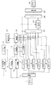
図1は、本実施形態における動画像処理装置の概要構成を示すブロック図である。本実施形態においては、動画像符号化方式としてMPEG4符号化方式を用いた場合について説明する。尚、本実施形態における符号化方式はMPEG4に限らず、画像内の複数のオブジェクトを各々符号化することができれば、どのような方式であってもよい。
【0031】
図1において、201は符号化器であり、動画像を取り込んでMPEG4符号化方式のCoreプロファイル・レベル2による符号化を行なう。202は記憶装置であり、符号化された動画像データを蓄積する。記憶装置202は磁気ディスクや光磁気ディスク等で構成されており、本装置に着脱可能であるため、他装置においても読み込むことができる。203は送信器であり、LANや通信回線への送信や、さらには放送等を行う。204は受信器であり、送信器203から出力された符号化データを受信する。205は本発明を適用したプロファイル・レベル調整部である。206はプロファイル・レベル調整部205の出力を蓄積する記憶装置である。207は復号器であり、MPEG4符号化方式のCoreプロファイル・レベル1による符号化データを復号可能とする。208は復号器207で復号された動画像を表示する表示器である。尚、上述したように符号化器201はCoreプロファイル・レベル2による符号化を行なうが、説明を容易にするため、384kbpsのビットレートで符号化するものとする。
【0032】
図15に、符号化する画像の構成例を示す。同図における各符号は、それぞれオブジェクトを示す。即ち、オブジェクト2000は背景、オブジェクト2001は空中を移動する気球、オブジェクト2002は小鳥をそれぞれ表し、また、オブジェクト2003,2004は人間を表す。
【0033】
図3の(a)は、図15の画像を符号化した際のビットストリームを示す図であり、先頭にオブジェクト2000〜2004の画面上での位置情報を表すオブジェクト配置情報αが存在する。オブジェクト配置情報αは、実際にはシーン構成情報を記述するBIFS(Binary Format for Scene description)言語によって符号化されて、別途多重化されている。そして、オブジェクト配置情報αに続いて、VOSSC符号、ビジュアルオブジェクトデータα-1,α-2,α-3、及びVOSEC符号が存在する。図3(a)に示す符号化データは、記憶装置202に蓄積されるか、又は送信器203を介して送出される。
【0034】
この符号化データは、記憶装置202や受信器204を介して本発明の特徴であるところのプロファイル・レベル調整部205に入力される。プロファイル・レベル調整部205には、復号器207の状態も入力されている。
【0035】
図2は、プロファイル・レベル調整部205の詳細構成を示すブロック図である。同図において、1は図3(a)に示す符号化データである。2は分離器であり、符号化データ1を、配置情報やヘッダ情報を表す符号化データと、各オブジェクトを表す符号化データとに分離する。3は分離された配置情報やヘッダ情報を表す符号化データを格納するヘッダメモリである。4〜8は符号メモリであり、オブジェクト毎に符号化データを格納する。9はプロファイル・レベル抽出器であり、符号化データ1からPLI符号を抽出し、プロファイルとレベルに関する情報を抽出する。10はオブジェクト計数器であり、符号化データ1に含まれるオブジェクトの数を計数する。
【0036】
11は復号器状態受信器であり、復号器207の符号化仕様(プロファイル・レベル)やその他の状況を獲得する。12はプロファイル・レベル入力器であり、不図示の端末等により任意のプロファイルやレベルの設定を行なう。13はプロファイル・レベル判定器であり、プロファイル・レベル抽出器9及びオブジェクト計数器10の出力と、復号器状態受信器11またはプロファイル・レベル入力器12から入力されるプロファイル・レベル情報とを比較して、オブジェクト数の調整の必要性の有無を判定する。
【0037】
14は符号長比較器であり、符号化データ1が入力される際に各オブジェクトの符号長を計数して比較することにより、オブジェクトの符号長順を決定する。15はヘッダ変更器であり、ヘッダメモリ3に格納されたヘッダ情報の内容を、プロファイル・レベル判定器13、符号長比較器14の出力に基づいて変更する。16は多重化器であり、ヘッダ変更器15の出力と、符号長比較器14の比較結果に基づいて、符号メモリ4〜8から読み出される符号化データを多重化する。17はプロファイル・レベル調整の結果として出力される符号化データである。
【0038】
以下、上述した構成からなるプロファイル・レベル調整部205における処理について、詳細に説明する。
【0039】
符号化データ1は、分離器2とプロファイル・レベル抽出器9、オブジェクト計数器10、符号長比較器14に入力される。分離器2は、符号化データ1を配置情報やヘッダ情報を表す符号化データと、各オブジェクトを表す符号化データとに分離し、それぞれの符号化データはヘッダメモリ3と、符号メモリ4〜8に格納される。例えば、ヘッダメモリ3には、図3(a)に示すオブジェクト配置情報α,VOSSC符号,Visual Object SC符号,visual_object_start_code符号,VOデータAの直前までの各符号,及び図19に示したVOLやVOPのヘッダ情報等が格納される。また、符号メモリ4〜8には、各オブジェクト毎にヘッダ情報が取り除かれたVOLデータ及びVOPデータが格納される。これらはヘッダを除去した部分がわかるように、個別に格納されている。例えば、図15に示す画像においてオブジェクトは5つあるので、オブジェクト2000〜2004の符号化データ(図3(a)中のVOデータA〜E)は、それぞれ符号メモリ4〜8に格納される。
【0040】
同時に、オブジェクト計数器10は、符号化データ1に含まれているオブジェクトの数を計数する。そして符号長比較器14は、各オブジェクトの符号長を計数する。
【0041】
プロファイル・レベル抽出器9は、符号化データ1からPLI_αを抽出し、復号して符号化データ1のプロファイル及びレベルに関する情報を抽出する。そして、抽出と同時に復号器状態受信器11を動作させ、復号器207において復号可能なプロファイルやレベル等の情報を獲得する。これらの情報は、プロファイル・レベル入力器12を介してユーザによって設定することも可能である。
【0042】
プロファイル・レベル判定器13は、上述したようにして獲得されたプロファイル及びレベル情報と、プロファイル・レベル抽出器9の抽出結果とを比較し、獲得されたプロファイル及びレベルが、符号化データ1から抽出されたプロファイル及びレベルよりも上位または同じであれば、ヘッダ変更器15は動作させず、ヘッダメモリ3、符号メモリ4〜8の内容を入力された符号化データを順に読み出し、多重化器16で多重化して符号化データ17を生成する。即ち、この場合の符号化データ17の内容は、符号化データ1の内容と同じである。
【0043】
一方、プロファイル・レベル判定器13における比較の結果、獲得されたプロファイル及びレベルが、符号化データ1から抽出されたプロファイル及びレベルよりも下位あれば、オブジェクト計数器10から符号化データ1に含まれるオブジェクトの数を入力し、該オブジェクト数を、復号器状態受信器11やプロファイル・レベル入力器12で獲得されたプロファイル及びレベルから判定される復号可能なオブジェクト数と比較する。
【0044】
そして、オブジェクト計数器10で得られたオブジェクト数が復号可能なオブジェクト数以下であれば、上述した、獲得されたプロファイル及びレベルが符号化データ1よりも上位または同じである場合と同様に、符号化データ17を生成する。
【0045】
一方、オブジェクト計数器10で得られたオブジェクト数が復号可能なオブジェクト数よりも大きければ、復号可能なオブジェクト数を符号長比較器14に入力し、符号長比較機能を動作させる。符号長比較器14においては、符号化データ1が有する複数のオブジェクトを、符号長の大きい順に、復号すべきオブジェクトとして設定する。即ち、符号長の大きいオブジェクトから順次、復号可能となるようにする。例えば図3(a)においては、各ビデオオブジェクトの符号長が、VOデータA,VOデータD,VOデータC,VOデータE,VOデータBの順であるとする。ここで復号器207においては、Coreプロファイル・レベル1による復号を行なうため、オブジェクト数が4つまでは復号が可能である。従って図3(a)の場合には、4つのオブジェクト、即ち、VOデータBを除く4つのオブジェクトが復号可能であることが分かる。従って、符号長比較器14は、VOデータBが格納されている符号メモリ5の読み出しを不可とし、それ以外の符号メモリ4,6,7,8を読み出し可能とする。
【0046】
そしてプロファイル・レベル判定器13はヘッダ変更器15を動作させ、PLIの内容を復号器207に合わせて変更して符号化し、符号長比較器14による比較結果に基づいて、復号器207において復号されない(廃棄される)オブジェクト(この場合、VOデータB)に関するヘッダ情報を削除する。即ち、符号化データ1のヘッダ情報を、復号器207における復号能力、または入力されたプロファイル及びレベルに適合した内容に置換える。そして更にオブジェクト配置情報αから、廃棄されたオブジェクト(VOデータB)に対応するオブジェクト2002に関する配置情報を削除して、新たなオブジェクト配置情報βを生成する。
【0047】
そして、ヘッダ変更器15及び符号メモリ4,6,7,8の内容を、入力された順に読み出し、多重化器16で多重化して符号化データ17を生成する。この時の符号化データ17のビットストリームを、図3(b)に示す。図3(b)によれば、新たに生成されたオブジェクト配置情報βに続いて、VOSSC符号、ビジュアルオブジェクトデータβ-1,β-2,β-3、及びVOSEC符号が存在する。このビジュアルオブジェクトデータβ-1,β-2,β-3は、図3(a)に示す元のビジュアルオブジェクトデータα-1,α-2,α-3に対して、オブジェクト数の調整を施したものである。例えばビジュアルオブジェクトデータβ-1は、Visual Object SC符号に続き、復号器207に適したプロファイル・レベルを表すPLI_β、及び、オブジェクト2002に関する符号化データ(VOデータB)が削除された符号により構成されている。
【0048】
このようにして得られた符号化データ17は、記憶装置206に格納されたり、又は復号器207で復号されて表示器208で表示される。図16に、符号化データ17を復号して表示した画像を示す。同図によれば、図15に示す符号化対象画像において小鳥を示していたオブジェクト2002が、削除されていることが分かる。
【0049】
尚、符号長比較器14においては、符号化データ1から直接符号長を計数するとして説明したが、符号メモリ4〜8に格納された符号化データに基づいて符号長を計数しても良い。
【0050】
以上説明したように本実施形態によれば、符号器と復号器において符号化仕様(プロファイルやレベル)が異なる場合においても、符号化データの復号が可能になる。また、符号長の最も短いオフジェクトデータを破棄することにより、破棄するオブジェクトの選択を容易とし、復号後の画像に与える影響を極力抑制することが可能になる。
【0051】
さらに、復号器207で復号可能なオブジェクト数が、符号化データ1の符号化仕様で規定されている数よりも少ない場合においても、復号器状態受信器11によって実際に復号可能なオブジェクト数を獲得することによって、同様な効果が得られる。
【0052】
加えて、復号器207の符号化仕様以上のビットレートの符号化仕様を有する符号化データが入力された場合でも、ビットレートを下げるようにオブジェクトを破棄することによって、復号器207における復号が可能となる。
【0053】
<第2実施形態>
以下、本発明に係る第2実施形態について説明する。
【0054】
尚、第2実施形態における動画像処理装置の概要構成は、上述した第1実施形態の図1と同様であるため、説明を省略する。
【0055】
図4は、第2実施形態におけるプロファイル・レベル調整部205の詳細構成を示すブロック図である。図4において、第1実施形態の図2と同様の構成には同一番号を付し、説明を省略する。第2実施形態においては、動画像符号化方式としてMPEG4符号化方式を用いた場合について説明するが、画像内の複数のオブジェクトを各々符号化することができれば、どのような符号化方式でも適用可能である。
【0056】
図4において、18はヘッダメモリ3から各オブジェクトのサイズを抽出して比較するサイズ比較器である。
【0057】
第1実施形態と同様に、符号化データ1は分離器2とプロファイル・レベル抽出器9,オブジェクト計数器10,及び符号長比較器14に入力され、各符号化データがヘッダメモリ3,符号メモリ4〜8に格納される。同時に、オブジェクト計数器10は符号化データに含まれているオブジェクトの数を計数する。
【0058】
サイズ比較器18は、各オブジェクトごとのサイズを抽出する。ここで、各オブジェクトのサイズは、図19に示した符号化データのビットストリーム構成に示すVOL_width,VOL-heightの各符号を抽出し、復号することによって得られる。
【0059】
そして第1実施形態と同様に、プロファイル・レベル抽出器9は符号化データ1からプロファイルとレベルに関する情報を抽出し、同時に復号器状態受信器11から復号器207のプロファイル及びレベル等の情報を獲得するか、又はプロファイル・レベル入力器12からユーザによってプロファイル及びレベルが設定される。
【0060】
プロファイル・レベル判定器13は、上述したようにして獲得されたプロファイル及びレベル情報と、プロファイル・レベル抽出器9の抽出結果とを比較し、獲得されたプロファイル及びレベルが符号化データ1から抽出されたプロファイル及びレベルよりも上位または同じであれば、ヘッダ変更器15は動作させず、符号化データ1と同様の符号化データ17を生成する。
【0061】
一方、プロファイル・レベル判定器13における比較の結果、獲得されたプロファイル及びレベルが、符号化データ1から抽出されたプロファイル及びレベルよりも下位あれば、オブジェクト計数器10から符号化データ1に含まれるオブジェクトの数を入力し、該オブジェクト数を、復号器状態受信器11やプロファイル・レベル入力器12で獲得されたプロファイル及びレベルから判定される復号可能なオブジェクト数と比較する。
【0062】
そして、オブジェクト計数器10で得られたオブジェクト数が復号可能なオブジェクト数以下であれば、上述した、獲得されたプロファイル及びレベルが符号化データ1よりも上位または同じである場合と同様に、符号化データ17を生成する。
【0063】
一方、オブジェクト計数器10で得られたオブジェクト数が復号可能なオブジェクト数よりも大きければ、復号可能なオブジェクト数をサイズ比較器18に入力し、サイズ比較機能を動作させる。サイズ比較器18においては、符号化データ1が有する複数のオブジェクトを、サイズの大きい順に、復号すべきオブジェクトとして設定する。即ち、サイズの大きいオブジェクトから順次、復号可能となるようにする。例えば図15における各オブジェクトのサイズは、オブジェクト2000,2004,2001,2003,2002の順に大きい。ここで復号器207においては、Coreプロファイル・レベル1による復号を行なうため、オブジェクト数が4つまでは復号が可能である。従って図15に示す画像の場合には、もっとも小さいオブジェクト2002を除けば、残り4つのオブジェクトが復号可能であることが分かる。従って、サイズ比較器18は、オブジェクト2002の符号化データが格納されている符号メモリ5の読み出しを不可とし、それ以外の符号メモリ4,6,7,8を読み出し可能とする。
【0064】
そして第1実施形態と同様に、プロファイル・レベル判定器13はヘッダ変更器15を動作させ、PLIの内容を復号器207に合わせて変更して符号化し、更に、サイズ比較器18による比較結果に基づいて、復号器207において復号されない(廃棄される)オブジェクト(この場合、オブジェクト2002)に関するヘッダ情報を削除する。そして更にオブジェクト配置情報αから、廃棄されたオブジェクト2002に関する配置情報を削除して、新たなオブジェクト配置情報βを生成する。
【0065】
そして、ヘッダ変更器15及び符号メモリ4,6,7,8の内容を、入力された順に読み出し、多重化器16で多重化して符号化データ17を生成する。この時の符号化データ17のビットストリームは、図3(b)に示す通りである。
【0066】
このようにして得られた符号化データ17は、記憶装置206に格納されたり、又は復号器207で復号されて、図16に示すような画像として表示器208に表示される。
【0067】
また、サイズ比較器18においては、符号化データ1のVOL_width,VOL_height符号に基づいてオブジェクトのサイズを抽出するとして説明したが、VOP_width,VOP_height符号により抽出しても構わないし、実際に形状(マスク)情報を表す符号化データを復号して得られた形状(マスク)情報に基づいて、オブジェクトサイズを抽出しても良い。
【0068】
以上説明したように第2実施形態によれば、符号器と復号器において符号化仕様が異なる場合においても、符号化データの復号が可能になる。また、オブジェクトサイズの最も小さいオフジェクトデータを破棄することにより、破棄するオブジェクトの選択を容易とし、復号後の画像に与える影響を極力抑制することが可能になる。
【0069】
尚、第1及び第2実施形態においては、1つのオブジェクトを廃棄する例について説明したが、もちろん2つ以上のオブジェクトを廃棄することも可能である。また、廃棄するオブジェクトを、ユーザが直接指定可能なように構成することも可能である。
【0070】
また、プロファイル・レベル入力器12によって、予め画像のオブジェクト毎に廃棄の順番を設定しておくことも可能である。
【0071】
<第3実施形態>
以下、本発明に係る第3実施形態について説明する。
【0072】
尚、第3実施形態における動画像処理装置の概要構成は、上述した第1実施形態の図1と同様であるため、説明を省略する。
【0073】
図5は、第3実施形態におけるプロファイル・レベル調整部205の詳細構成を示すブロック図である。図5において、第1実施形態の図2と同様の構成には同一番号を付し、説明を省略する。第3実施形態においては、動画像符号化方式としてMPEG4符号化方式を用いた場合について説明するが、画像内の複数のオブジェクトを各々符号化することができれば、どのような符号化方式でも適用可能である。
【0074】
図5において、20はオブジェクト選択指示器であり、複数のオブジェクトを表示し、ユーザによって任意のオブジェクトの選択及び指示が入力される。21はオブジェクト選択器であり、オブジェクト選択指示器20からの指示と、プロファイル・レベル判定器13における判定結果に基づいて、実際に処理対象となるオブジェクトの符号化データを選択するオブジェクト選択器である。22,24はセレクタであり、オブジェクト選択器21によって制御され、入出力を切り替える。23は複数のオブジェクトを統合するオブジェクト統合器である。25は入力される符号化データを多重化する多重化器である。
【0075】
上述した第1実施形態と同様に、符号化データ1は、分離器2とプロファイル・レベル抽出器9、オブジェクト計数器10に入力される。分離器2は、符号化データ1を配置情報やヘッダ情報を表す符号化データと、各オブジェクトを表す符号化データとに分離し、それぞれの符号化データはヘッダメモリ3と、符号メモリ4〜8に格納される。同時に、オブジェクト計数器10は、符号化データ1に含まれているオブジェクトの数を計数する。
【0076】
そして第1実施形態と同様に、プロファイル・レベル抽出器9は符号化データ1からプロファイルとレベルに関する情報を抽出し、同時に復号器状態受信器11から復号器207のプロファイル及びレベル等の情報を獲得するか、又はプロファイル・レベル入力器12からユーザによってプロファイル及びレベルが設定される。
【0077】
プロファイル・レベル判定器13は、上述したようにして獲得されたプロファイル及びレベル情報と、プロファイル・レベル抽出器9の抽出結果とを比較し、獲得されたプロファイル及びレベルが符号化データ1から抽出されたプロファイル及びレベルよりも上位または同じであれば、オブジェクト選択器21はセレクタ22及び24を直結する経路を選択する。即ち、符号化データがオブジェクト統合器23を通過しないようにする。そして、ヘッダ変更器15を動作させずに、ヘッダメモリ3、符号メモリ4〜8に格納された符号化データを入力された順に読み出して多重化器25で多重化することにより、符号化データ1と同様の符号化データ26を生成する。
【0078】
一方、プロファイル・レベル判定器13における比較の結果、獲得されたプロファイル及びレベルが、符号化データ1から抽出されたプロファイル及びレベルよりも下位あれば、オブジェクト計数器10から符号化データ1に含まれるオブジェクトの数を入力し、該オブジェクト数を、復号器状態受信器11やプロファイル・レベル入力器12で獲得されたプロファイル及びレベルから判定される復号可能なオブジェクト数と比較する。
【0079】
そして、オブジェクト計数器10で得られたオブジェクト数が復号可能なオブジェクト数以下であれば、上述した、獲得されたプロファイル及びレベルが符号化データ1よりも上位または同じである場合と同様に、符号化データ26を生成する。
【0080】
一方、オブジェクト計数器10で得られたオブジェクト数が復号可能なオブジェクト数よりも大きければ、復号可能なオブジェクト数をオブジェクト選択器21に入力する。オブジェクト選択器21は、各オブジェクトの状態(例えば図15に示す画像)や、各オブジェクトに関する情報、及び統合するオブジェクト数等の情報を、オブジェクト選択指示器20に表示する。ユーザはこれらの情報に従って、統合処理を行うオブジェクトを選定し、その指示をオブジェクト選択指示器20に与える。
【0081】
ここで、第3実施形態における復号器207はCoreプロファイル・レベル1による復号を行なうため、復号可能なオブジェクト数は4つまでである。従って、例えば図15に示す画像は5つのオブジェクトを有するため、そのうちの2つを統合して1つのオブジェクトとすることにより、復号器207において復号可能な符号化データを得ることができる。以下、図15に示す画像においてオブジェクト2003とオブジェクト2004を統合することをユーザが指示した場合を例として、以下に説明する。
【0082】
ユーザにより、オブジェクト選択指示器20を介して統合対象のオブジェクトが指示されると、プロファイル・レベル判定器13はヘッダ変更器15を動作させ、PLIの内容を復号器207に合わせて変更して、更にオブジェクト選択器21による選択結果に基づいて、統合して得られる新たなオブジェクトに関するヘッダ情報の生成、及び統合により廃棄されるオブジェクトに関するヘッダ情報の削除を行なう。具体的には、オブジェクト2003及び2004のオブジェクト配置情報に基づいて、統合結果として得られる新たなオブジェクトの配置情報を生成し、元のオブジェクト2003及び2004のオブジェクト配置情報を削除する。そして、オブジェクト2003及び2004のヘッダ情報に基づいて、統合して得られるオブジェクトの大きさやその他の情報をヘッダ情報として生成し、元のオブジェクト2003及び2004のヘッダ情報を削除する。
【0083】
オブジェクト選択器21は、オブジェクト2003及び2004の符号化データに関してはオブジェクト統合器23において後述する統合処理を行い、その他の符号化データに関してはオブジェクト統合器23を介さないように、セレクタ22,24の入出力を制御する。
【0084】
そして、ヘッダ変更器15及びオブジェクト2000〜2002の符号化データを格納した符号メモリ4,5,6の内容を入力された順に読み出し、セレクタ22,24を介して多重化器25で多重化する。一方、統合対象であるオブジェクト2003,2004の符号データを格納した符号メモリ7,8の内容は、セレクタ22を介してオブジェクト統合器23に入力される。
【0085】
図6は、オブジェクト統合器23の詳細構成を示すブロック図である。同図において、50,51は符号メモリであり、統合するオブジェクトの符号化データをそれぞれ格納する。52,54はセレクタであり、オブジェクト毎に入出力を切り替える。53はオブジェクト復号器であり、符号化データを復号し、オブジェクトの画像を再生する。55,56はフレームメモリであり、再生された画像をオブジェクト毎に格納する。57は合成器であり、ヘッダメモリ3に格納されている統合対象のオブジェクトの配置情報に従って、オブジェクトを合成する。58はオブジェクト符号化器であり、合成して得られた画像データを符号化して出力する。
【0086】
以下、オブジェクト統合器23の動作について詳細に説明する。符号メモリ50,51には、それぞれ統合対象であるオブジェクト2003,2004の符号化データが格納される。まず、セレクタ52は符号メモリ50側の入力を選択し、セレクタ54はフレームメモリ55側の出力を選択する。その後、符号メモリ50から符号化データが読み出され、オブジェクト復号器53で復号された後、セレクタ54を介してフレームメモリ55にオブジェクト2003の画像情報が書き込まれる。このオブジェクト2003の画像データは、カラー画像を表す画像データと形状を表すマスク情報からなる。続いて、セレクタ52,54の入出力をそれぞれ他方側に切り替えて同様の処理を行なうことにより、オブジェクト2004の画像情報をフレームメモリ56に格納する。
【0087】
合成器57は、ヘッダメモリ3からオブジェクト2003,2004の位置情報及びサイズ情報を取得して、統合後の新たなオブジェクトのサイズ、該新たなオブジェクト内における元のオブジェクト2003,2004のそれぞれの相対位置を求めることができる。そして、フレームメモリ55,56の情報を読み出し、カラー画像情報とマスク情報のそれぞれを合成する。カラー画像情報の合成結果を図9に示し、マスク情報の合成結果を図10に示す。これらのカラー画像情報及びマスク情報は、オブジェクト符号化器58においてMPEG4のオブジェクト符号化方式に従って符号化された後、オブジェクト統合器23から出力される。
【0088】
オブジェクト統合器23から出力された符号化データは、セレクタ24を介して多重化器25で他の符号化データに多重化され、符号化データ26を得る。図7に、符号化データ26のビットストリームを示す。図7は即ち、図3(a)に示す符号化データ1に対して、第3実施形態の統合処理を施した結果を示す。図7によれば、統合結果として新たに得られたオブジェクトの配置情報を含むオブジェクト配置情報γに続いて、VOSSC符号、ビジュアルオブジェクトデータγ-1,γ-2,γ-3、及びVOSEC符号が存在する。このビジュアルオブジェクトデータγ-1,γ-2,γ-3は、図3(a)に示す元のビジュアルオブジェクトデータα-1,α-2,α-3に対して、オブジェクトの統合調整を施したものである。例えばビジュアルオブジェクトデータγ-1は、Visual Object SC符号に続き、復号器207に適したプロファイル・レベルを表すPLI_γ、オブジェクト2000〜2002の各符号化データであるVOデータA,VOデータB,VOデータC、及びオブジェクト2003及び2004を統合して得られた符号化データVOデータGにより構成されている。
【0089】
このようにして得られた符号化データ26は、記憶装置206に格納されたり、又は復号器207で復号されて図15に示す画像として復元され、表示器208に表示される。
【0090】
尚、第3実施形態においては、オブジェクト選択指示器20によって、ユーザが画像内における統合対象オブジェクトを選択指示する例について説明したが、本発明はもちろんこの例に限定されるものではない。例えば、まずオブジェクト選択指示器20によって画像のオブジェクト毎に、予め統合の順番を設定しておく。そして、復号器207で復号可能なオブジェクト数が該画像のオブジェクト数が下回り、オブジェクト統合の必要が生じた場合に、該設定された順番に従って自動的にオブジェクト統合を行なうように構成することも可能である。
【0091】
以上説明したように第3実施形態によれば、符号器と復号器においてプロファイルやレベルが異なる場合においても、符号化データの復号が可能になる。また、オブジェクトを統合して復号することによって、復号後のオブジェクトの喪失を防ぐことができる。
【0092】
さらに、オブジェクト選択指示器20とオブジェクト選択器21に代えて、オブジェクト統合器を第1及び第2実施形態で示した符号長比較器14やサイズ比較器18等を備えることにより、符号長の短いオブジェクト順や、サイズの小さいオブジェクト順に統合処理を行なうことが可能である。
【0093】
<<変形例>>
図8は、第3実施形態におけるオブジェクト統合器23の変形構成例を示すブロック図である。図8において、図6と同様の構成には同一番号を付し、説明を省略する。図8においては、符号長カウンタ59を更に設けることを特徴とする。符号長カウンタ59により統合前の各オブジェクトの符号化データの符号長を計数し、オブジェクト符号化器58の出力の符号長が該係数結果と同じになるように、オフジェクト符号化器58のパラメータ(例えば量子化パラメータ等)を調整する。これにより、全体の符号長を増やすことなく、オブジェクト合成を行なうことが可能となる。
【0094】
<第4実施形態>
以下、本発明に係る第4実施形態について説明する。第4実施形態においては、上述した第3実施形態と同様に、オブジェクトの統合処理を行なうことを特徴とする。尚、第4実施形態における動画像処理装置の概要構成、及びプロファイル・レベル調整部205の詳細構成は、上述した第1及び第3実施形態における図1及び図5と同様であるため、説明を省略する。
【0095】
図11は、第4実施形態におけるオブジェクト統合器23の詳細構成を示すブロック図である。図11において、第3実施形態の図6と同様の構成には同一番号を付し、説明を省略する。
【0096】
図11において、60,61は分離器であり、入力された符号化データを、形状を表すマスク情報に関する符号化データと、カラー画像情報を表す符号化データとに分離して出力する。62,63,64,65は符号メモリであり、符号メモリ62,64はカラー画像情報を表す符号化データを、符号メモリ63,65はマスク情報に関する符号化データを、それぞれのオブジェクト毎に格納する。66はカラー画像情報を表す符号化データを符号化データのままで合成するカラー画像情報符号合成器である。67はマスク情報を表す符号化データを合成するマスク情報符号合成器である。
【0097】
以下、第4実施形態におけるオブジェクト統合器23の動作について詳細に説明する。第3実施形態と同様に、まず符号メモリ50,51にオブジェクト2003,2004の符号化データがそれぞれ格納される。符号メモリ50に格納されたオブジェクト2003の符号化データは、フレーム単位(VOP単位)で読み出され、分離器60でカラー画像情報符号化データとマスク情報符号化データとに分離され、それぞれの符号化データは符号メモリ62,63に格納される。同様に、オブジェクト2004のカラー画像情報符号化データ及びマスク情報符号化データは、それぞれ符号メモリ64,65に格納される。
【0098】
この後、カラー画像情報符号合成器66は、符号メモリ62,64からカラー画像情報符号化データをそれぞれ読み出す。また、第3実施形態と同様に、ヘッダメモリ3からオブジェクト2003,2004の位置情報及びサイズ情報を取得して、統合後の新たなオブジェクトのサイズ、該新たなオブジェクト内における元のオブジェクト2003,2004のそれぞれの相対位置を求める。即ちカラー画像情報符号合成器66においては、これらのカラー画像情報符号化データを統合した後に復号すると、図9に示す様な画像が1つのオブジェクトとして得られることを想定した合成を行なう。
【0099】
ここでMPEG4符号化方式においては、スライスというデータ構造を持っており、複数のマクロブロックを主走査方向に連続する1つの魂として定義することができる。図9に示すオブジェクトに対してスライス構造を適用した例を図12に示す。図12においては、太枠で囲まれた領域が1つのスライスとして定義され、各スライス毎に先頭のマクロブロックをハッチングにより示している。
【0100】
カラー画像情報符号合成器66は、図12に示すように、統合結果として得られる画像の左上に相当するマクロブロックのデータから順に、右方向(主走査方向)に読み出しを行う。即ち、まずオブジェクト2003の符号化データのうち、先頭スライスの先頭マクロブロックに相当する符号化データが符号メモリ62から読み出される。そして、スライスのヘッダ情報を付加した後、先頭マクロブロックの符号化データをそのまま出力し、次に右方向のマクロブロックの読み出し及び出力を、当該スライスの間順次繰り返す。
【0101】
尚、オブジェクト2003,2004の間の新たにデータが発生した部分に関しても新たなスライスとして考える。この部分はマスク情報によって復号されても表示されない部分であるため、適当な画素を補填する。即ち、これらの部分はオブジェクトを含む最後のマクロブロックのDC成分のみで構成されるとする。するとDC差分は0であり、AC係数も全て0であるため、符号は発生しない。
【0102】
そして、オブジェクト2004の境界において、新たなスライスが開始されたとして、図12においてハッチングで示されたマクロブロックを新たなスライスの先頭とし、スライスのヘッダ情報を付加する。この場合、先頭のマクロブロックのアドレスは相対アドレスであるため、前のオブジェクトを含むマクロブロックからの相対アドレスに変換する。尚、マクロブロックが他のマクロブロックを参照してDC等の予測を行っていれば、その部分は再符号化し、その後は順次右方向に、マクロブロックの符号データをそのまま出力していく。即ち、オブジェクトの境界でスライスヘッダを付加し、スライス先頭のマクロブロックの予測を、初期化した状態の符号に置き換える。こうして得られた符号は、多重化器68に出力される。
【0103】
カラー画像情報符号合成器66の動作と並行して、マスク情報符号合成器67においては、符号メモリ63,65からマスク情報符号化データをそれぞれ読み出す。そして、ヘッダメモリ3からオブジェクト2003,2004の位置情報及びサイズ情報を取得して、統合後の新たなオブジェクトのサイズ、該新たなオブジェクト内における元のオブジェクト2003,2004のそれぞれの相対位置を求める。そして、入力されたマスク情報符号化データを復号し、合成することによって、図10に示すマスク画像を得る。このマスク画像を、MPEG4の形状情報符号化方式である算術符号化方式により符号化する。こうして得られた符号は、多重化器68に出力される。
【0104】
但し、マスク情報の符号化としては、MPEG4における算術符号化方式に限らない。例えば、マスク情報符号化データの合成結果においては、オブジェクト境界間における0ランが長くなるだけであるので、ファクシミリ装置において使用される0ランを符号化する方式等を適用することにより、マスク情報符号合成器67において復号を行なうことなく、0ラン長を表す符号を置換えるだけで合成が行える。一般に、マスク情報を算術符号化方式又はその他の符号化方式により符号化した際に、その符号長の変化は僅かである。
【0105】
多重化器68においては、統合されたカラー画像情報に関する符号化データと、マスク情報符号化データとを多重化して、1つのオブジェクトの符号化データとする。以降の処理は上述した第3実施形態と同様であり、多重化器25において他の符号化データと多重化されて出力される。
【0106】
以上説明したように第4実施形態によれば、符号器と復号器においてプロファイルやレベルが異なる場合においても、符号化データの復号が可能になる。また、オブジェクトを符号化データのままで統合することによって、ヘッダ情報を僅かに付加するのみで、復号後のオブジェクトの喪失を防ぐことができる。
【0107】
更に、第4実施形態におけるオブジェクト統合処理において、新たに付加されるヘッダは僅かな演算によって得られ、また、符号の変更もスライスの先頭ブロックに限定されるため、第3実施形態に示した復号・再符号化によるオブジェクト統合処理に比べて高速化が図れる。
【0108】
<第5実施形態>
以下、本発明に係る第5実施形態について説明する。第5実施形態においては、上述した第3実施形態と同様に、オブジェクトの統合処理を行なうことを特徴とする。尚、第5実施形態における動画像処理装置の概要構成は、上述した第1実施形態の図1と同様であるため、説明を省略する。
【0109】
図13は、第5実施形態におけるプロファイル・レベル調整部205の詳細構成を示すブロック図である。図13において、第3実施形態の図5と同様の構成には同一番号を付し、説明を省略する。第5実施形態においては、動画像符号化方式としてMPEG4符号化方式を用いた場合について説明するが、画像内の複数のオブジェクトを各々符号化することができれば、どのような符号化方式でも適用可能である。
【0110】
図13において、70はオブジェクト配置情報判定器であり、統合対象となるオブジェクトを決定する。
【0111】
プロファイル・レベル判定器13においては第3実施形態と同様に、復号器207のプロファイル及びレベル情報と、符号化データ1のプロファイル・レベルとを比較するが、ここで、復号器207のプロファイル及びレベルが符号化データ1のプロファイル及びレベルよりも上位または同じであっても、また、下位であっても、、オブジェクト計数器10で得られたオブジェクト数が復号器207において復号可能なオブジェクト数以下であれば、第3実施形態と同様の手順で符号化データ26を生成する。
【0112】
一方、オブジェクト計数器10で得られたオブジェクト数が、復号器207において復号可能なオブジェクト数よりも大きければ、復号可能なオブジェクト数をオブジェクト配置情報判定器70に入力する。ここで、第3実施形態と同様に、復号器207において復号可能なオブジェクト数は4つまでである。従って、図15に示す5つのオブジェクトを有する画像において、2つのオブジェクトを統合することにより、復号可能な符号化データを得ることができる。
【0113】
オブジェクト配置情報判定器70においては、ヘッダメモリ3から各オブジェクトの位置情報及びサイズ情報を抽出し、統合する2つのオブジェクトを下記の条件に基づいて決定する。尚、上記条件は、(1),(2)の順に優先とする。
【0114】
(1)一方のオブジェクトが他方のオブジェクトに包含されている
(2)両オブジェクト間の距離が最も短い
図15に示す画像においては、オブジェクト2001〜2004が、オブジェクト2000に含まれている。従って、オブジェクト配置情報判定器70においては、オブジェクト2000とオブジェクト2001を統合対象として決定する。
【0115】
統合対象オブジェクトが決定されると、第3実施例と同様にプロファイル・レベル判定器13はヘッダ変更器15を動作させ、PLIの内容を復号器207に合わせて変更して符号化し、更にオブジェクト配置情報判定器70による判定結果に基づいて、統合して得られる新たなオブジェクトに関するヘッダ情報の生成、及び統合により廃棄されるオブジェクトに関するヘッダ情報の削除を行なう。具体的には、オブジェクト2000及び2001のオブジェクト配置情報に基づいて、統合結果として得られる新たなオブジェクトの配置情報を生成し、元のオブジェクト2000及び2001のオブジェクト配置情報を削除する。そして、オブジェクト2000及び2001のヘッダ情報に基づいて、統合して得られるオブジェクトの大きさやその他の情報をヘッダ情報として生成し、元のオブジェクト2000及び2001のヘッダ情報を削除する。
【0116】
オブジェクト配置判定器70は、オブジェクト2000及び2001の符号化データに関してはオブジェクト統合器23において統合処理を行い、その他の符号化データに関してはオブジェクト統合器23を介さないように、セレクタ22,24の入出力を制御する。
【0117】
そして、ヘッダ変更器15及びオブジェクト2002〜2004の符号化データを格納した符号メモリ6,7,8の内容を入力された順に読み出し、セレクタ22,24を介して多重化器25に入力される。一方、統合対象であるオブジェクト2000,2001の符号データを格納した符号メモリ4,5の内容は、セレクタ22を介してオブジェクト統合器23で統合された後、多重化器25に入力される。そして多重化器25でこれらの符号化データを多重化することにより、符号化データ26が得られる。尚、オブジェクト統合器23における統合処理は、上述した第3実施形態又は第4実施形態と同様に実現される。
【0118】
ここで、図14に、第5実施形態における符号化データ26のビットストリームを示す。図14は即ち、図3(a)に示す符号化データ1に対して、第5実施形態の統合処理を施した結果を示す。図14によれば、統合結果として新たに得られたオブジェクトの配置情報を含むオブジェクト配置情報δに続いて、VOSSC符号、ビジュアルオブジェクトデータδ-1,δ-2,δ-3、及びVOSEC符号が存在する。このビジュアルオブジェクトデータδ-1,δ-2,δ-3は、図3(a)に示す元のビジュアルオブジェクトデータα-1,α-2,α-3に対して、オブジェクトの統合調整を施したものである。例えばビジュアルオブジェクトデータδ-1は、Visual Object SC符号に続き、復号器207に適したプロファイル・レベルを表すPLI_δ、オブジェクト2000及び2001を統合して得られた符号化データVOデータH、オブジェクト2002〜2004の各符号化データであるVOデータC,VOデータD,VOデータEにより構成されている。
【0119】
このようにして得られた符号化データ26は、記憶装置206に格納されたり、又は復号器207で復号されて図15に示す画像として復元され、表示器208に表示される。
【0120】
尚、上述した第1又は第2実施形態と同様に、各オブジェクトの符号長やオブジェクトサイズ等を、第5実施形態における統合オブジェクトの判定条件に加えても良い。
【0121】
以上説明したように第5実施形態によれば、符号器と復号器においてプロファイルやレベルが異なる場合においても、符号化データの復号が可能になる。
【0122】
また、オブジェクトの位置関係に基づいて統合することによって、統合によって変化してしまう符号量を最小限に抑制しつつ、復号後のオブジェクトの喪失を防ぐことができる。
【0123】
尚、第5実施形態においてはオブジェクトの位置関係に基づいて統合するオブジェクトを決定する例について説明したが、上述した第1及び第2実施形態においても、廃棄するオブジェクトをオブジェクトの位置関係に基づいて選択することも可能である。
【0124】
尚、第3乃至第5実施形態においては、2つのオブジェクトを統合して1つのオブジェクトを生成する例について説明したが、もちろん3つ以上のオブジェクトを統合したり、または、2組以上の統合を行なうことも可能である。
【0125】
尚、上述した第1乃至第5実施形態における符号メモリ4〜8やヘッダメモリ3の構成は図2に示す例に限定されず、より多くの符号メモリを設けても構わないし、1つのメモリを複数領域に分割して使用したり、磁気ディスク等の記憶媒体を使用してもちろん構わない。
【0126】
また、廃棄又は統合対象となるオブジェクトの選択についても、オブジェクトのサイズや符号長、位置関係、ユーザによる指示等、複数の条件を組み合わせて決定しても良い。
【0127】
また、本発明を画像編集装置に適用すれば、編集処理によってオブジェクトの数が変化しても、その出力を任意のプロファイルやレベルに適合させることが可能となる。
【0128】
<他の実施形態>
なお、本発明は、複数の機器(例えばホストコンピュータ,インタフェイス機器,リーダ,プリンタなど)から構成されるシステムに適用しても、一つの機器からなる装置(例えば、複写機,ファクシミリ装置など)に適用してもよい。
【0129】
また、本発明の目的は、前述した実施形態の機能を実現するソフトウェアのプログラムコードを記録した記憶媒体を、システムあるいは装置に供給し、そのシステムあるいは装置のコンピュータ(またはCPUやMPU)が記憶媒体に格納されたプログラムコードを読出し実行することによっても、達成されることは言うまでもない。
【0130】
この場合、記憶媒体から読出されたプログラムコード自体が前述した実施形態の機能を実現することになり、そのプログラムコードを記憶した記憶媒体は本発明を構成することになる。
【0131】
プログラムコードを供給するための記憶媒体としては、例えば、フロッピディスク,ハードディスク,光ディスク,光磁気ディスク,CD−ROM,CD−R,磁気テープ,不揮発性のメモリカード,ROMなどを用いることができる。
【0132】
また、コンピュータが読出したプログラムコードを実行することにより、前述した実施形態の機能が実現されるだけでなく、そのプログラムコードの指示に基づき、コンピュータ上で稼働しているOS(オペレーティングシステム)などが実際の処理の一部または全部を行い、その処理によって前述した実施形態の機能が実現される場合も含まれることは言うまでもない。
【0133】
さらに、記憶媒体から読出されたプログラムコードが、コンピュータに挿入された機能拡張ボードやコンピュータに接続された機能拡張ユニットに備わるメモリに書込まれた後、そのプログラムコードの指示に基づき、その機能拡張ボードや機能拡張ユニットに備わるCPUなどが実際の処理の一部または全部を行い、その処理によって前述した実施形態の機能が実現される場合も含まれることは言うまでもない。本発明を上記記憶媒体に適用する場合、その記憶媒体には、先に説明したフローチャートに対応するプログラムコードを格納することになる。
【0134】
【発明の効果】
以上説明したように本発明によれば、複数の画像情報(オブジェクト)毎に符号化された符号化データを、任意の符号化仕様の復号器で最適に復号することが可能となる。
【0135】
また、符号化データに含まれるオブジェクト数を調整することが可能となる。
【図面の簡単な説明】
【図1】本発明を適用した動画像処理装置の構成を示すブロック図、
【図2】第1実施形態におけるプロファイル・レベル調整部の構成を示すブロック図、
【図3】動画像の符号化データの構成例を示す図、
【図4】第2実施形態におけるプロファイル・レベル調整部の構成を示すブロック図、
【図5】第3実施形態におけるプロファイル・レベル調整部の構成を示すブロック図、
【図6】第3実施形態におけるオブジェクト統合器の構成を示すブロック図、
【図7】第3実施形態における統合後の符号化データの構成例を示す図、
【図8】第3実施形態の変形例におけるオブジェクト統合器の構成を示すブロック図、
【図9】第3実施形態におけるカラー画像情報の合成例を示す図、
【図10】第3実施形態におけるマスク情報の合成例を示す図、
【図11】第4実施形態におけるオブジェクト統合器の構成を示すブロック図、
【図12】第4実施形態におけるカラー画像情報のスライス構造を示す図、
【図13】第5実施形態におけるプロファイル・レベル調整部の構成を示すブロック図、
【図14】第5実施形態における統合後の動画像符号化データの構成例を示す図、
【図15】符号化データの表す画像の構成例を示す図、
【図16】符号化データの表す画像の構成例を示す図、
【図17】 MPEG4規格による符号化器の構成例を示す図、
【図18】 MPEG4規格による復号器の構成例を示す図、
【図19】 MPEG4規格による動画像符号化データの構成例を示す図、
【図20】 MPEG4規格によるプロファイル表、である。
【符号の説明】
1,17,26 符号化データ
2,60,61,1006 分離器
3 ヘッダメモリ
4,5,6,7,8,50,51,62,63,64,65 符号メモリ
9 プロファイル・レベル抽出器
10 オブジェクト計数器
11 復号器状態受信器
12 プロファイル・レベル入力器
13 プロファイル・レベル判定器
14 符号長比較器
15 ヘッダ変更器
16,25,68,1005 多重化器
18 サイズ比較器
20 オブジェクト選択指示器
21 オブジェクト選択器
22,24,52,54 セレクタ
23 オブジェクト統合器
53,1007,1008,1009 オブジェクト復号器
55,56 フレームメモリ
57,1010 合成器
58,1002,1003,1004 オブジェクト符号化器
59 符号長カウンタ
66 カラー画像情報符号合成器
67 マスク情報符号合成器
70 オブジェクト配置情報判定器
201 符号化器
202,206 記憶装置
203 送信器
204 受信器
205 プロファイル・レベル調整部
207 復号器
208 表示器
1001 オブジェクト定義器
1011 配置情報符号化器
1012 配置情報復号器
2000,2001,2002,2003,2004 オブジェクト[0001]
BACKGROUND OF THE INVENTION
The present invention relates to a data processing apparatus and method, and a data processing system for processing a data sequence constituting one image by using a plurality of encoded image information.
[0002]
[Prior art]
In recent years, standardization of the MPEG4 (Moving Picture Experts Group Phase 4) standard has been promoted as a new encoding method for moving images. In the conventional moving image encoding method represented by the MPEG2 standard, encoding is performed in units of frames or fields. However, content (person, building, voice, sound, etc.) constituting video or audio of the moving image is used. In the MPEG4 standard, video data and audio data are handled as objects (objects) in order to realize the reuse and editing of the background. Furthermore, the objects included in the video data are independently encoded, and each can be handled as an object.
[0003]
FIG. 17 shows a functional block diagram of an encoder based on the MPEG4 standard, and FIG. 18 shows a functional block diagram of a decoder that decodes data encoded by the encoder. In FIG. 17, input image data is divided into objects by an object definer 1001, and is encoded by
[0004]
When the encoded data is input to the decoder shown in FIG. 18, the
[0005]
As described above, according to the MPEG4 standard, various objects can be freely arranged on the decoding side by individually handling the objects in the moving image. Also, broadcasts, content creation companies, and the like can generate a large amount of moving image data from limited content by generating encoded data of objects in advance.
[0006]
[Problems to be solved by the invention]
However, as described above, since the MPEG4 standard encoding method handles an unspecified number of objects, the decoding side, in particular, may determine the number of decoding means sufficient to support decoding of all objects. Therefore, it was very difficult to construct an apparatus or a system.
[0007]
Therefore, the standardized MPEG4 standard defines the concept of profile and level, and the encoding specification consisting of profile and level so that the specification can be determined in the design of encoded data and encoder / decoder. As described above, upper limit values of the number of objects and the bit rate are provided. FIG. 20 shows an example of a profile table that defines the upper limit of each requirement for each profile level.
[0008]
As shown in the profile table of Fig. 20, in the MPEG4 standard, the combination of means (tools) used for encoding differs depending on the profile, and the amount of encoded data of the image to be handled is divided in stages according to the level. It has been. Here, the maximum value of the number of objects that can be handled and the maximum value of the bit rate both represent the upper limit in the encoding specification, and any value less than that is included in the encoding specification. For example, if a tool that can be used in the Core profile is used and the number of objects is six and encoding is performed at 300 kbps, the encoded data (encoder) corresponds to
[0009]
Here, FIG. 19 shows an example of a bit stream of MPEG4 encoded data. The above-described profile and level are represented by the code profile_and_level_indication (PLI in the figure) in the bitstream. In MPEG4, object arrangement information is encoded in a system description language, and this information is written at the top for convenience. Actually, it is multiplexed together with other encoding results as appropriate.
[0010]
MPEG4 encoded data is hierarchized from the viewpoint of improving encoding efficiency and editing operability. As shown in FIG. 19, there is visual_object_sequence_start_code (VOSSC in the figure) for identification at the beginning of the encoded data of the moving image, followed by the encoded data of each visual object, and finally after the encoded data. There is visual_object_sequence_end_code (VOSEC in the figure) indicating the end. Here, in addition to the captured moving image, CG data and the like are defined as the visual object.
[0011]
As details of the visual object, there is a visual_object_start_code (Visual Object SC in the figure) for identification at the top, followed by the PLI described above. After that, is_visual_object_identifier (IVOI in the figure), visual_object_verid (VOVID in the figure), visual_object_priority (VOPRI in the figure), visual_object_type (VOTYPE in the figure), etc., which represent the information of the visual object, constitutes the header information of the visual object. is doing. Here, visual_object_type (VOTYPE) is, for example, “0001” when the image is a moving image, and is followed by video object (VO) data representing the soul of the encoded data of the moving image. .
[0012]
Video object data is encoded data representing each object, and includes video object layer data (VOL) for realizing scalability and video object plane data (VOP) corresponding to one frame of a moving image. Each header part has codes video_object_layer_width (VOL_width in the figure), video_object_layer_height (VOL_height in the figure), video_object_plane_width (VOP_width in the figure), and video_object_plane_height (VOP_height in the figure) representing the size.
[0013]
A decoder that decodes this bit stream can determine whether or not decoding is possible by referring to the PLI code. That is, decoding cannot be performed in the following cases.
[0014]
For example, a
[0015]
Further, it is conceivable to generate encoded data of
[0016]
For example, when two encoded data (each object number is 2) of Simple profile 48 kbps and 8 kbps are multiplexed to generate a new bit stream, the bit rate may not be within 64 kbps. In such a case, it is necessary to set the level to 2, that is, decoding cannot be performed by a
[0017]
As described above, when the encoding specification (profile and level) of the decoder cannot sufficiently include the encoding specification (profile and level) of the encoded data, the encoded data cannot be decoded. It was.
[0018]
The present invention has been made in order to solve the above-described problem. The encoded data encoded for each of a plurality of pieces of image information (objects) is converted into a decoder having an arbitrary encoding specification. Optimally An object of the present invention is to provide a data processing apparatus and method, and a data processing system capable of decoding.
[0019]
It is another object of the present invention to provide a data processing apparatus and method, and a data processing system capable of adjusting the number of objects included in encoded data.
[0020]
[Means for Solving the Problems]
As a means for achieving the above object, a data processing apparatus of the present invention comprises the following arrangement.
[0021]
That is, a data processing apparatus for processing encoded image data including a plurality of encoded objects, the encoded image data The object contained within From encoder Profile and level Extracting means for extracting A decoder for decoding the encoded image data; Decoder Profile and level Acquisition means for acquiring Profile and level And the decoder Profile and level And compare When the decoder profile and level are lower than the encoder profile and level, the number of objects in the encoded image data is detected, and the number of detected objects is the profile and level of the decoder. If there are more objects than can be decoded by the decoder obtained from And changing means for changing the number of objects in the encoded image data.
[0023]
As a means for achieving the above object, the data processing system of the present invention comprises the following arrangement.
[0024]
That is, an encoding means for generating encoded image data constituting one image by encoding a plurality of objects, and the encoded image data The object contained within To the encoding means Profile and level Extraction means for extracting the information of The decoding means for decoding the encoded image data Of decryption means Profile and level Obtaining means for obtaining the encoding means; and Profile and level And the decoding means Profile and level And compare When the profile and level of the decoding means are lower than the profile and level of the encoding means, the number of objects in the encoded image data is detected, and the number of detected objects is the profile and level of the decoding means. More than the number of objects decodable by the decoding means obtained from It has a change means for changing the number of objects in the encoded image data, and a decoding means for decoding the changed encoded image data.
[0026]
As a technique for achieving the above object, the data processing method of the present invention includes the following steps.
[0027]
That is, a data processing method for processing encoded image data including a plurality of encoded objects, the encoded image data The object contained within From encoder Profile and level An extraction process for extracting A decoder for decoding the encoded image data; Decoder Profile and level An acquisition step of acquiring Profile and level And the decoder Profile and level And compare When the decoder profile and level are lower than the encoder profile and level, the number of objects in the encoded image data is detected, and the number of detected objects is the profile and level of the decoder. When the number of objects that can be decoded by the decoder is larger than the encoded image, It is characterized by changing the number of objects in the data.
[0029]
DETAILED DESCRIPTION OF THE INVENTION
Hereinafter, an embodiment according to the present invention will be described in detail with reference to the drawings.
[0030]
<First Embodiment>
FIG. 1 is a block diagram showing a schematic configuration of a moving image processing apparatus according to the present embodiment. In this embodiment, a case where the MPEG4 encoding method is used as the moving image encoding method will be described. The encoding method in the present embodiment is not limited to MPEG4, and any method may be used as long as a plurality of objects in an image can be encoded.
[0031]
In FIG. 1,
[0032]
FIG. 15 shows a configuration example of an image to be encoded. Each code | symbol in the figure shows an object, respectively. That is, the
[0033]
(A) of FIG. 3 is a diagram illustrating a bit stream when the image of FIG. 15 is encoded, and object arrangement information α representing position information on the screen of the
[0034]
The encoded data is input to the profile /
[0035]
FIG. 2 is a block diagram showing a detailed configuration of the profile /
[0036]
[0037]
[0038]
Hereinafter, processing in the profile /
[0039]
The encoded
[0040]
At the same time, the
[0041]
The profile /
[0042]
The profile /
[0043]
On the other hand, if the acquired profile and level are lower than the profile and level extracted from the encoded
[0044]
If the number of objects obtained by the
[0045]
On the other hand, if the number of objects obtained by the
[0046]
Then, the profile /
[0047]
Then, the contents of the
[0048]
The encoded
[0049]
Although the
[0050]
As described above, according to the present embodiment, it is possible to decode encoded data even when the encoding specifications (profile and level) are different between the encoder and the decoder. Further, by discarding the object data with the shortest code length, it is possible to easily select an object to be discarded and suppress the influence on the decoded image as much as possible.
[0051]
Furthermore, even when the number of objects that can be decoded by the
[0052]
In addition, even when encoded data having a bit rate encoding specification higher than that of the
[0053]
<Second Embodiment>
Hereinafter, a second embodiment according to the present invention will be described.
[0054]
Note that the schematic configuration of the moving image processing apparatus according to the second embodiment is the same as that of FIG.
[0055]
FIG. 4 is a block diagram showing a detailed configuration of the profile /
[0056]
In FIG. 4,
[0057]
As in the first embodiment, the encoded
[0058]
The
[0059]
As in the first embodiment, the profile /
[0060]
The profile /
[0061]
On the other hand, if the acquired profile and level are lower than the profile and level extracted from the encoded
[0062]
If the number of objects obtained by the
[0063]
On the other hand, if the number of objects obtained by the
[0064]
As in the first embodiment, the profile /
[0065]
Then, the contents of the
[0066]
The encoded
[0067]
The
[0068]
As described above, according to the second embodiment, it is possible to decode encoded data even when the encoding specifications differ between the encoder and the decoder. Further, by discarding the object data having the smallest object size, it is possible to easily select an object to be discarded and to suppress the influence on the decoded image as much as possible.
[0069]
In the first and second embodiments, an example in which one object is discarded has been described. Of course, two or more objects can be discarded. Further, it is possible to configure the object to be discarded so that the user can directly specify it.
[0070]
It is also possible to set the discard order for each object of the image in advance by the profile /
[0071]
<Third embodiment>
The third embodiment according to the present invention will be described below.
[0072]
Note that the schematic configuration of the moving image processing apparatus according to the third embodiment is the same as that of FIG. 1 of the first embodiment described above, and a description thereof will be omitted.
[0073]
FIG. 5 is a block diagram showing a detailed configuration of the profile /
[0074]
In FIG. 5,
[0075]
Similar to the first embodiment described above, the encoded
[0076]
As in the first embodiment, the profile /
[0077]
The profile /
[0078]
On the other hand, if the acquired profile and level are lower than the profile and level extracted from the encoded
[0079]
If the number of objects obtained by the
[0080]
On the other hand, if the number of objects obtained by the
[0081]
Here, since the
[0082]
When an object to be integrated is instructed by the user via the
[0083]
The
[0084]
Then, the contents of the
[0085]
FIG. 6 is a block diagram showing a detailed configuration of the
[0086]
Hereinafter, the operation of the
[0087]
The
[0088]
The encoded data output from the
[0089]
The encoded
[0090]
In the third embodiment, the example in which the user selects and instructs the integration target object in the image using the
[0091]
As described above, according to the third embodiment, it is possible to decode the encoded data even when the encoder and the decoder have different profiles and levels. Also, by integrating and decoding the objects, it is possible to prevent loss of the objects after decoding.
[0092]
Furthermore, instead of the
[0093]
<< Modification >>
FIG. 8 is a block diagram showing a modified configuration example of the
[0094]
<Fourth embodiment>
The fourth embodiment according to the present invention will be described below. The fourth embodiment is characterized in that object integration processing is performed as in the third embodiment described above. Note that the schematic configuration of the moving image processing apparatus in the fourth embodiment and the detailed configuration of the profile /
[0095]
FIG. 11 is a block diagram showing a detailed configuration of the
[0096]
In FIG. 11,
[0097]
Hereinafter, the operation of the
[0098]
Thereafter, the color image
[0099]
Here, the MPEG4 encoding system has a data structure called a slice, and a plurality of macroblocks can be defined as one soul continuous in the main scanning direction. An example in which the slice structure is applied to the object shown in FIG. 9 is shown in FIG. In FIG. 12, a region surrounded by a thick frame is defined as one slice, and the top macroblock is indicated by hatching for each slice.
[0100]
As shown in FIG. 12, the color image
[0101]
Note that a portion where new data is generated between the
[0102]
Then, assuming that a new slice is started at the boundary of the
[0103]
In parallel with the operation of the color image
[0104]
However, the encoding of the mask information is not limited to the arithmetic encoding method in MPEG4. For example, in the synthesis result of the mask information encoded data, the 0 run between the object boundaries only becomes long. Therefore, by applying a method for encoding the 0 run used in the facsimile machine, the mask information code The synthesis can be performed only by replacing the code representing the 0 run length without decoding in the
[0105]
In the
[0106]
As described above, according to the fourth embodiment, it is possible to decode the encoded data even when the encoder and the decoder have different profiles and levels. Further, by integrating the objects as encoded data, it is possible to prevent loss of the decoded object by adding a little header information.
[0107]
Furthermore, in the object integration processing in the fourth embodiment, the newly added header is obtained by a few operations, and the code change is also limited to the first block of the slice, so the decoding shown in the third embodiment -Higher speed than object integration processing by re-encoding.
[0108]
<Fifth embodiment>
Hereinafter, a fifth embodiment according to the present invention will be described. The fifth embodiment is characterized in that object integration processing is performed in the same manner as in the third embodiment described above. Note that the schematic configuration of the moving image processing apparatus according to the fifth embodiment is the same as that of FIG.
[0109]
FIG. 13 is a block diagram showing a detailed configuration of the profile /
[0110]
In FIG. 13,
[0111]
The profile /
[0112]
On the other hand, if the number of objects obtained by the
[0113]
The object arrangement
[0114]
(1) One object is included in the other object
(2) The shortest distance between both objects
In the image shown in FIG. 15, the
[0115]
When the integration target object is determined, the profile /
[0116]
The object
[0117]
Then, the contents of the
[0118]
Here, FIG. 14 shows a bit stream of the encoded
[0119]
The encoded
[0120]
As in the first or second embodiment described above, the code length, object size, and the like of each object may be added to the integrated object determination conditions in the fifth embodiment.
[0121]
As described above, according to the fifth embodiment, it is possible to decode the encoded data even when the encoder and the decoder have different profiles and levels.
[0122]
Further, by integrating based on the positional relationship of objects, it is possible to prevent loss of the object after decoding while minimizing the code amount that changes due to the integration.
[0123]
In the fifth embodiment, the example of determining the objects to be integrated based on the positional relationship of the objects has been described. However, in the first and second embodiments described above, the objects to be discarded are determined based on the positional relationship of the objects. It is also possible to select.
[0124]
In the third to fifth embodiments, the example in which two objects are integrated to generate one object has been described. Of course, three or more objects are integrated, or two or more sets are integrated. It is also possible to do this.
[0125]
Note that the configurations of the
[0126]
The selection of objects to be discarded or integrated may also be determined by combining a plurality of conditions such as the object size, code length, positional relationship, and user instructions.
[0127]
Further, if the present invention is applied to an image editing apparatus, the output can be adapted to an arbitrary profile or level even if the number of objects changes due to editing processing.
[0128]
<Other embodiments>
Note that the present invention can be applied to a system including a plurality of devices (for example, a host computer, an interface device, a reader, a printer, etc.), or a device (for example, a copier, a facsimile device, etc.) including a single device. You may apply to.
[0129]
Another object of the present invention is to supply a storage medium storing software program codes for implementing the functions of the above-described embodiments to a system or apparatus, and the computer (or CPU or MPU) of the system or apparatus stores the storage medium. Needless to say, this can also be achieved by reading and executing the program code stored in the.
[0130]
In this case, the program code itself read from the storage medium realizes the functions of the above-described embodiments, and the storage medium storing the program code constitutes the present invention.
[0131]
As a storage medium for supplying the program code, for example, a floppy disk, a hard disk, an optical disk, a magneto-optical disk, a CD-ROM, a CD-R, a magnetic tape, a nonvolatile memory card, a ROM, or the like can be used.
[0132]
Further, by executing the program code read by the computer, not only the functions of the above-described embodiments are realized, but also an OS (operating system) operating on the computer based on the instruction of the program code. It goes without saying that a case where the function of the above-described embodiment is realized by performing part or all of the actual processing and the processing is included.
[0133]
Further, after the program code read from the storage medium is written into a memory provided in a function expansion board inserted into the computer or a function expansion unit connected to the computer, the function expansion is performed based on the instruction of the program code. It goes without saying that the CPU or the like provided in the board or the function expansion unit performs part or all of the actual processing, and the functions of the above-described embodiments are realized by the processing. When the present invention is applied to the storage medium, the storage medium stores program codes corresponding to the flowcharts described above.
[0134]
【The invention's effect】
As described above, according to the present invention, encoded data encoded for each of a plurality of pieces of image information (objects) is converted by a decoder having an arbitrary encoding specification. Optimally Decoding is possible.
[0135]
Also, the number of objects included in the encoded data can be adjusted.
[Brief description of the drawings]
FIG. 1 is a block diagram showing a configuration of a moving image processing apparatus to which the present invention is applied;
FIG. 2 is a block diagram showing a configuration of a profile / level adjustment unit in the first embodiment;
FIG. 3 is a diagram showing a configuration example of encoded data of a moving image;
FIG. 4 is a block diagram showing a configuration of a profile / level adjustment unit according to the second embodiment;
FIG. 5 is a block diagram showing a configuration of a profile / level adjustment unit according to the third embodiment;
FIG. 6 is a block diagram showing a configuration of an object integrator in the third embodiment;
FIG. 7 is a diagram showing a configuration example of encoded data after integration in the third embodiment;
FIG. 8 is a block diagram showing a configuration of an object integrator in a modification of the third embodiment;
FIG. 9 is a view showing a synthesis example of color image information in the third embodiment;
FIG. 10 is a diagram showing a synthesis example of mask information in the third embodiment;
FIG. 11 is a block diagram showing a configuration of an object integrator in the fourth embodiment;
FIG. 12 is a diagram showing a slice structure of color image information in the fourth embodiment;
FIG. 13 is a block diagram showing the configuration of a profile / level adjustment unit in the fifth embodiment;
FIG. 14 is a diagram showing a configuration example of video encoded data after integration in the fifth embodiment;
FIG. 15 is a diagram illustrating a configuration example of an image represented by encoded data;
FIG. 16 is a diagram showing a configuration example of an image represented by encoded data;
FIG. 17 is a diagram showing a configuration example of an encoder according to the MPEG4 standard;
FIG. 18 is a diagram showing a configuration example of a decoder according to the MPEG4 standard;
FIG. 19 is a diagram showing a configuration example of moving image encoded data according to the MPEG4 standard;
FIG. 20 is a profile table according to the MPEG4 standard.
[Explanation of symbols]
1, 17, 26 Encoded data
2, 60, 61, 1006 separator
3 Header memory
4, 5, 6, 7, 8, 50, 51, 62, 63, 64, 65 Code memory
9 Profile level extractor
10 Object counter
11 Decoder status receiver
12 Profile level input device
13 Profile level detector
14 Code length comparator
15 Header changer
16, 25, 68, 1005 Multiplexer
18 size comparator
20 Object selection indicator
21 Object selector
22, 24, 52, 54 selector
23 Object integrator
53, 1007, 1008, 1009 Object decoder
55, 56 frame memory
57,1010 Synthesizer
58, 1002, 1003, 1004 Object encoder
59 Code length counter
66 Color image information code synthesizer
67 Mask information code synthesizer
70 Object placement information determiner
201 Encoder
202,206 Storage device
203 Transmitter
204 Receiver
205 Profile level adjustment section
207 Decoder
208 Display
1001 Object definer
1011 Configuration information encoder
1012 Configuration information decoder
2000, 2001, 2002, 2003, 2004 objects
Claims (24)
前記符号化画像データ内に含まれる該オブジェクトから符号器のプロファイル及びレベルを抽出する抽出手段と、
前記符号化画像データを復号する復号器から該復号器のプロファイル及びレベルを取得する取得手段と、
前記符号器のプロファイル及びレベルと前記復号器のプロファイル及びレベルとを比較し、前記復号器のプロファイル及びレベルが前記符号器のプロファイル及びレベルよりも下位の場合に、前記符号化画像データ中のオブジェクトの数を検出し、検出されたオブジェクトの数が前記復号器のプロファイル及びレベルから得られる該復号器で復号可能なオブジェクト数よりも多い場合に、前記符号化画像データ中のオブジェクトの数を変更する変更手段と
を有することを特徴とするデータ処理装置。A data processing apparatus for processing encoded image data including a plurality of encoded objects,
Extraction means for extracting the profile and level of the encoder from the object contained in the encoded image data;
Acquisition means for acquiring the profile and level of the decoder from the decoder for decoding the coded image data,
Comparing the profile and level of the encoder with the profile and level of the decoder, and if the profile and level of the decoder is lower than the profile and level of the encoder, the object in the encoded image data If the number of detected objects is larger than the number of objects decodable by the decoder obtained from the profile and level of the decoder , the number of objects in the encoded image data is changed. A data processing apparatus.
前記符号化画像データ中の複数のオブジェクトを選択する選択手段と、
該選択された複数のオブジェクトを統合する統合手段と、を有することを特徴とする請求項5記載のデータ処理装置。The changing means is
Selecting means for selecting a plurality of objects in the encoded image data;
6. The data processing apparatus according to claim 5 , further comprising an integration unit that integrates the plurality of selected objects.
前記選択手段により選択された複数のオブジェクトを復号する復号手段と、
該復号された複数のオブジェクトを合成する合成手段と、
該合成されたオブジェクトを符号化する符号化手段と、を有することを特徴とする請求項6記載のデータ処理装置。The integration means includes
Decoding means for decoding a plurality of objects selected by the selection means;
Combining means for combining the plurality of decrypted objects;
7. The data processing apparatus according to claim 6 , further comprising encoding means for encoding the synthesized object.
前記符号化手段は、該計数手段による計数結果に基づいて、符号化パラメータを制御することを特徴とする請求項8記載のデータ処理装置。And a counting means for counting the code length of the object selected by the selecting means,
9. The data processing apparatus according to claim 8 , wherein the encoding unit controls an encoding parameter based on a counting result by the counting unit.
前記選択手段により選択された複数のオブジェクトをそれぞれ色情報とマスク情報とに分離する分離手段と、
該分離された色情報を合成する色情報合成手段と、
該分離されたマスク情報を合成するマスク情報合成手段と、
前記合成された色情報及びマスク情報を多重化する多重化手段と、を有することを特徴とする請求項6記載のデータ処理装置。The integration means includes
Separating means for separating the plurality of objects selected by the selecting means into color information and mask information, respectively;
Color information synthesizing means for synthesizing the separated color information;
Mask information synthesizing means for synthesizing the separated mask information;
7. A data processing apparatus according to claim 6 , further comprising multiplexing means for multiplexing the synthesized color information and mask information.
前記符号化画像データ内に含まれる該オブジェクトから前記符号化手段のプロファイル及びレベルの情報を抽出する抽出手段と、
前記符号化画像データを復号する復号手段から該復号手段のプロファイル及びレベルを取得する取得手段と、
前記符号化手段のプロファイル及びレベルと前記復号手段のプロファイル及びレベルとを比較し、前記復号手段のプロファイル及びレベルが前記符号手段のプロファイル及びレベルよりも下位の場合に、前記符号化画像データ中のオブジェクトの数を検出し、検出されたオブジェクトの数が前記復号手段のプロファイル及びレベルから得られる該復号手段で復号可能なオブジェクト数よりも多い場合に、前記符号化画像データ中のオブジェクトの数を変更する変更手段と、
該変更された前記符号化画像データを復号する前記復号手段と、を有することを特徴とするデータ処理システム。Encoding means for encoding a plurality of objects to generate encoded image data constituting one image;
Extraction means for extracting profile and level information of the encoding means from the object included in the encoded image data;
Acquisition means for acquiring the profile and level of the decoding means from the decoding means for decoding the coded image data,
It compares the profile and level of profile and level and the decoding means of the encoding means, the profile and level of the decoding means in the case of lower than the profile and level of said code means, in the coded image data When the number of objects is detected and the number of detected objects is larger than the number of objects that can be decoded by the decoding means obtained from the profile and level of the decoding means, the number of objects in the encoded image data is determined. Change means to change;
A data processing system comprising: the decoding means for decoding the changed encoded image data.
前記符号化画像データ内に含まれる該オブジェクトから符号器のプロファイル及びレベルを抽出する抽出工程と、
前記符号化画像データを復号する復号器から該復号器のプロファイル及びレベルを取得する取得工程とを備え、
前記符号器のプロファイル及びレベルと前記復号器のプロファイル及びレベルとを比較し、前記復号器のプロファイル及びレベルが前記符号器のプロファイル及びレベルよりも下位の場合に、前記符号化画像データ中のオブジェクトの数を検出し、検出されたオブジェクトの数が前記復号器のプロファイル及びレベルから得られる該復号器で復号可能なオブジェクト数よりも多い場合に、前記符号化画像データ中のオブジェクトの数を変更することを特徴とするデータ処理方法。A data processing method for processing encoded image data including a plurality of encoded objects,
An extraction step of extracting an encoder profile and level from the object included in the encoded image data;
A obtaining step of obtaining the profile and level of the decoder from the decoder for decoding the coded image data,
Comparing the profile and level of the encoder with the profile and level of the decoder, and if the profile and level of the decoder is lower than the profile and level of the encoder, the object in the encoded image data If the number of detected objects is larger than the number of objects decodable by the decoder obtained from the profile and level of the decoder , the number of objects in the encoded image data is changed. And a data processing method.
前記符号化画像データ内に含まれる該オブジェクトから前記符号化手段のプロファイル及びレベルを抽出する抽出工程と、
前記符号化画像データを復号する復号手段から該復号手段のプロファイル及びレベルを取得する取得工程と、
前記符号化手段のプロファイル及びレベルと前記復号手段のプロファイル及びレベルとを比較し、前記復号手段のプロファイル及びレベルが前記符号手段のプロファイル及びレベルよりも下位の場合に、前記符号化画像データ中のオブジェクトの数を検出し、検出されたオブジェクトの数が前記復号手段のプロファイル及びレベルから得られる該復号手段で復号可能なオブジェクト数よりも多い場合に、前記符号化画像データ中のオブジェクトの数を変更する変更工程と、
該変更された前記符号化画像データを前記復号手段で復号する復号工程と、を有することを特徴とするデータ処理方法。An encoding step of generating encoded image data that forms one image by encoding a plurality of objects, respectively;
An extraction step of extracting the profile and level of the encoding means from the object contained in the encoded image data;
An acquisition step of acquiring the profile and level of the decoding means from the decoding means for decoding the coded image data,
It compares the profile and level of profile and level and the decoding means of the encoding means, the profile and level of the decoding means in the case of lower than the profile and level of said code means, in the coded image data When the number of objects is detected and the number of detected objects is larger than the number of objects that can be decoded by the decoding means obtained from the profile and level of the decoding means, the number of objects in the encoded image data is determined. Change process to change,
And a decoding step of decoding the changed encoded image data by the decoding means.
前記符号化画像データ内に含まれる該オブジェクトから符号器のプロファイル及びレベルを抽出する抽出工程と、
復号器のプロファイル及びレベルを取得する取得工程とを備え、
前記符号器のプロファイル及びレベルと前記復号器のプロファイル及びレベルとを比較し、前記復号器のプロファイル及びレベルが前記符号器のプロファイル及びレベルよりも下位の場合に、前記符号化画像データ中のオブジェクトの数を検出し、検出されたオブジェクトの数が前記復号器のプロファイル及びレベルから得られる該復号器で復号可能なオブジェクト数よりも多い場合に、前記符号化画像データ中のオブジェクトの数を変更することを特徴とするデータ処理方法を
コンピュータに実行させるためのデータ処理プログラムが記録されたコンピュータで読取り可能な記録媒体。A data processing method for processing encoded image data including a plurality of encoded objects,
An extraction step of extracting an encoder profile and level from the object included in the encoded image data;
Obtaining a profile and level of the decoder, and
Comparing the profile and level of the encoder with the profile and level of the decoder, and if the profile and level of the decoder is lower than the profile and level of the encoder, the object in the encoded image data If the number of detected objects is larger than the number of objects decodable by the decoder obtained from the profile and level of the decoder , the number of objects in the encoded image data is changed. A computer-readable recording medium on which a data processing program for causing a computer to execute the data processing method is recorded.
Priority Applications (4)
| Application Number | Priority Date | Filing Date | Title |
|---|---|---|---|
| JP32563598A JP3854737B2 (en) | 1998-11-16 | 1998-11-16 | Data processing apparatus and method, and data processing system |
| US09/298,951 US6512793B1 (en) | 1998-04-28 | 1999-04-26 | Data processing apparatus and method |
| EP99303221A EP0954181B1 (en) | 1998-04-28 | 1999-04-26 | Data processing apparatus and method |
| DE69937816T DE69937816T2 (en) | 1998-04-28 | 1999-04-26 | Data processing device and method |
Applications Claiming Priority (1)
| Application Number | Priority Date | Filing Date | Title |
|---|---|---|---|
| JP32563598A JP3854737B2 (en) | 1998-11-16 | 1998-11-16 | Data processing apparatus and method, and data processing system |
Publications (2)
| Publication Number | Publication Date |
|---|---|
| JP2000152234A JP2000152234A (en) | 2000-05-30 |
| JP3854737B2 true JP3854737B2 (en) | 2006-12-06 |
Family
ID=18179051
Family Applications (1)
| Application Number | Title | Priority Date | Filing Date |
|---|---|---|---|
| JP32563598A Expired - Fee Related JP3854737B2 (en) | 1998-04-28 | 1998-11-16 | Data processing apparatus and method, and data processing system |
Country Status (1)
| Country | Link |
|---|---|
| JP (1) | JP3854737B2 (en) |
Families Citing this family (16)
| Publication number | Priority date | Publication date | Assignee | Title |
|---|---|---|---|---|
| JP3918447B2 (en) * | 2001-03-30 | 2007-05-23 | 三菱電機株式会社 | Moving image receiving apparatus and moving image transmitting apparatus |
| EP1765018B1 (en) * | 2002-02-01 | 2008-01-16 | Matsushita Electric Industrial Co., Ltd. | Moving picture decoding method and moving picture decoding apparatus |
| JP4008428B2 (en) | 2004-04-26 | 2007-11-14 | 富士通株式会社 | Image compression method |
| JP3936708B2 (en) * | 2004-05-26 | 2007-06-27 | 日本電信電話株式会社 | Image communication system, communication conference system, hierarchical encoding device, server device, image communication method, image communication program, and image communication program recording medium |
| US8074248B2 (en) | 2005-07-26 | 2011-12-06 | Activevideo Networks, Inc. | System and method for providing video content associated with a source image to a television in a communication network |
| EP2105019A2 (en) * | 2006-09-29 | 2009-09-30 | Avinity Systems B.V. | Method for streaming parallel user sessions, system and computer software |
| EP2632164A3 (en) | 2007-01-12 | 2014-02-26 | ActiveVideo Networks, Inc. | Interactive encoded content system including object models for viewing on a remote device |
| US9826197B2 (en) | 2007-01-12 | 2017-11-21 | Activevideo Networks, Inc. | Providing television broadcasts over a managed network and interactive content over an unmanaged network to a client device |
| JP5866125B2 (en) | 2010-10-14 | 2016-02-17 | アクティブビデオ ネットワークス, インコーポレイテッド | Digital video streaming between video devices using a cable TV system |
| US9204203B2 (en) | 2011-04-07 | 2015-12-01 | Activevideo Networks, Inc. | Reduction of latency in video distribution networks using adaptive bit rates |
| US10409445B2 (en) | 2012-01-09 | 2019-09-10 | Activevideo Networks, Inc. | Rendering of an interactive lean-backward user interface on a television |
| US9123084B2 (en) | 2012-04-12 | 2015-09-01 | Activevideo Networks, Inc. | Graphical application integration with MPEG objects |
| WO2014145921A1 (en) | 2013-03-15 | 2014-09-18 | Activevideo Networks, Inc. | A multiple-mode system and method for providing user selectable video content |
| US9294785B2 (en) | 2013-06-06 | 2016-03-22 | Activevideo Networks, Inc. | System and method for exploiting scene graph information in construction of an encoded video sequence |
| US9326047B2 (en) | 2013-06-06 | 2016-04-26 | Activevideo Networks, Inc. | Overlay rendering of user interface onto source video |
| US9219922B2 (en) | 2013-06-06 | 2015-12-22 | Activevideo Networks, Inc. | System and method for exploiting scene graph information in construction of an encoded video sequence |
-
1998
- 1998-11-16 JP JP32563598A patent/JP3854737B2/en not_active Expired - Fee Related
Also Published As
| Publication number | Publication date |
|---|---|
| JP2000152234A (en) | 2000-05-30 |
Similar Documents
| Publication | Publication Date | Title |
|---|---|---|
| US6512793B1 (en) | Data processing apparatus and method | |
| JP3854737B2 (en) | Data processing apparatus and method, and data processing system | |
| US6546189B1 (en) | Method and apparatus for editing compressed moving pictures and storage medium | |
| US6989868B2 (en) | Method of converting format of encoded video data and apparatus therefor | |
| KR100750520B1 (en) | Apparatus and method for generating encoded streams, data transmission system and method, editing system and method | |
| US6377309B1 (en) | Image processing apparatus and method for reproducing at least an image from a digital data sequence | |
| KR100766740B1 (en) | Apparatus and method for converting data using encoding history information | |
| US8570360B2 (en) | Stereoscopic parameter embedding device and stereoscopic image reproducer | |
| JP5072893B2 (en) | Image encoding method and image decoding method | |
| KR101194480B1 (en) | Three-dimensional video conversion recording device, three-dimensional video conversion recording method, recording medium, three-dimensional video conversion device, and three-dimensional video transmission device | |
| GB2378836A (en) | Image transcoder | |
| KR100701443B1 (en) | Transcoding Method of Coded Video Signals and Transcoder of Motion Vector Selection | |
| JP2010110007A (en) | Image encoding method and image decoding method, image encoding apparatus and image decoding apparatus, and image encoded bitstream and recording medium | |
| US20110211634A1 (en) | Method and apparatus for offset metadata insertion in multi-view coded view | |
| JP2004187161A (en) | Moving video data processing equipment and moving video data processing method | |
| JPH1023407A (en) | Device and method for encoding picture device and method for decoding picture, picture transmitting method, and recording medium | |
| JP5170708B2 (en) | Moving picture stream processing method and apparatus, moving picture reproduction apparatus and moving picture distribution apparatus using the same | |
| JP2001274689A (en) | Device and method for processing data | |
| KR100724206B1 (en) | Information processing apparatus, methods and recording media | |
| US6845214B1 (en) | Video apparatus and re-encoder therefor | |
| US20120307882A1 (en) | Method for transporting information and/or application data inside a digital video stream, and relative devices for generating and playing such video stream | |
| JP3854738B2 (en) | Data processing apparatus and method, and data processing system | |
| JPH09139912A (en) | Encoded data editing device and data decoding device | |
| JP3854717B2 (en) | Decoding apparatus and method | |
| JP3897499B2 (en) | Encoding apparatus and encoding method |
Legal Events
| Date | Code | Title | Description |
|---|---|---|---|
| A131 | Notification of reasons for refusal |
Free format text: JAPANESE INTERMEDIATE CODE: A131 Effective date: 20060206 |
|
| A521 | Written amendment |
Free format text: JAPANESE INTERMEDIATE CODE: A523 Effective date: 20060407 |
|
| A131 | Notification of reasons for refusal |
Free format text: JAPANESE INTERMEDIATE CODE: A131 Effective date: 20060602 |
|
| A521 | Written amendment |
Free format text: JAPANESE INTERMEDIATE CODE: A523 Effective date: 20060731 |
|
| TRDD | Decision of grant or rejection written | ||
| A01 | Written decision to grant a patent or to grant a registration (utility model) |
Free format text: JAPANESE INTERMEDIATE CODE: A01 Effective date: 20060825 |
|
| A61 | First payment of annual fees (during grant procedure) |
Free format text: JAPANESE INTERMEDIATE CODE: A61 Effective date: 20060911 |
|
| R150 | Certificate of patent or registration of utility model |
Free format text: JAPANESE INTERMEDIATE CODE: R150 |
|
| FPAY | Renewal fee payment (event date is renewal date of database) |
Free format text: PAYMENT UNTIL: 20090915 Year of fee payment: 3 |
|
| FPAY | Renewal fee payment (event date is renewal date of database) |
Free format text: PAYMENT UNTIL: 20100915 Year of fee payment: 4 |
|
| FPAY | Renewal fee payment (event date is renewal date of database) |
Free format text: PAYMENT UNTIL: 20100915 Year of fee payment: 4 |
|
| FPAY | Renewal fee payment (event date is renewal date of database) |
Free format text: PAYMENT UNTIL: 20110915 Year of fee payment: 5 |
|
| FPAY | Renewal fee payment (event date is renewal date of database) |
Free format text: PAYMENT UNTIL: 20110915 Year of fee payment: 5 |
|
| FPAY | Renewal fee payment (event date is renewal date of database) |
Free format text: PAYMENT UNTIL: 20120915 Year of fee payment: 6 |
|
| FPAY | Renewal fee payment (event date is renewal date of database) |
Free format text: PAYMENT UNTIL: 20120915 Year of fee payment: 6 |
|
| FPAY | Renewal fee payment (event date is renewal date of database) |
Free format text: PAYMENT UNTIL: 20130915 Year of fee payment: 7 |
|
| LAPS | Cancellation because of no payment of annual fees |