JP3854234B2 - Focus monitor method and mask - Google Patents
Focus monitor method and mask Download PDFInfo
- Publication number
- JP3854234B2 JP3854234B2 JP2003046236A JP2003046236A JP3854234B2 JP 3854234 B2 JP3854234 B2 JP 3854234B2 JP 2003046236 A JP2003046236 A JP 2003046236A JP 2003046236 A JP2003046236 A JP 2003046236A JP 3854234 B2 JP3854234 B2 JP 3854234B2
- Authority
- JP
- Japan
- Prior art keywords
- pattern
- exposure
- monitor
- focus
- amount
- Prior art date
- Legal status (The legal status is an assumption and is not a legal conclusion. Google has not performed a legal analysis and makes no representation as to the accuracy of the status listed.)
- Expired - Fee Related
Links
Images


Classifications
-
- G—PHYSICS
- G03—PHOTOGRAPHY; CINEMATOGRAPHY; ANALOGOUS TECHNIQUES USING WAVES OTHER THAN OPTICAL WAVES; ELECTROGRAPHY; HOLOGRAPHY
- G03F—PHOTOMECHANICAL PRODUCTION OF TEXTURED OR PATTERNED SURFACES, e.g. FOR PRINTING, FOR PROCESSING OF SEMICONDUCTOR DEVICES; MATERIALS THEREFOR; ORIGINALS THEREFOR; APPARATUS SPECIALLY ADAPTED THEREFOR
- G03F7/00—Photomechanical, e.g. photolithographic, production of textured or patterned surfaces, e.g. printing surfaces; Materials therefor, e.g. comprising photoresists; Apparatus specially adapted therefor
- G03F7/70—Microphotolithographic exposure; Apparatus therefor
- G03F7/70483—Information management; Active and passive control; Testing; Wafer monitoring, e.g. pattern monitoring
- G03F7/70605—Workpiece metrology
- G03F7/70616—Monitoring the printed patterns
- G03F7/70641—Focus
-
- G—PHYSICS
- G03—PHOTOGRAPHY; CINEMATOGRAPHY; ANALOGOUS TECHNIQUES USING WAVES OTHER THAN OPTICAL WAVES; ELECTROGRAPHY; HOLOGRAPHY
- G03F—PHOTOMECHANICAL PRODUCTION OF TEXTURED OR PATTERNED SURFACES, e.g. FOR PRINTING, FOR PROCESSING OF SEMICONDUCTOR DEVICES; MATERIALS THEREFOR; ORIGINALS THEREFOR; APPARATUS SPECIALLY ADAPTED THEREFOR
- G03F1/00—Originals for photomechanical production of textured or patterned surfaces, e.g., masks, photo-masks, reticles; Mask blanks or pellicles therefor; Containers specially adapted therefor; Preparation thereof
- G03F1/38—Masks having auxiliary features, e.g. special coatings or marks for alignment or testing; Preparation thereof
- G03F1/44—Testing or measuring features, e.g. grid patterns, focus monitors, sawtooth scales or notched scales
Landscapes
- Physics & Mathematics (AREA)
- General Physics & Mathematics (AREA)
- Exposure And Positioning Against Photoresist Photosensitive Materials (AREA)
- Exposure Of Semiconductors, Excluding Electron Or Ion Beam Exposure (AREA)
- Preparing Plates And Mask In Photomechanical Process (AREA)
Description
【0001】
【発明の属する技術分野】
本発明は、半導体素子や液晶表示素子等の製造に関して投影露光装置におけるフォーカス条件を設定するのに適したフォーカスモニタ方法及びマスクに関する
【0002】
【従来の技術】
フォーカスずれ量を高精度かつ簡便に測定する方法として、フォーカスの変化が検出可能なパターン(フォーカスモニタパターン)が配置されたフォーカスモニタマスクを露光し、転写後におけるモニタマークの線幅を、線幅測定装置(光学式の線幅測長器、SEM等)、または、露光装置自体に内蔵された線幅測定機能を用いて測定し、その結果よりフォーカスの変動量を求める方法がある(例えば、特許文献1)。
【0003】
特許文献1に記載されたフォーカスモニタパターンにより、フォーカス量が変動してもデフォーカス量を測定することができる。しかしながら、設定露光量によっては、変換カーブが、露光量によって変化してしまう場合がある。設定露光量はデバイスのレイヤーごとに決められているが、レイヤー間の設定露光量に大きな差がある場合、フォーカスモニタパターンにとっての最適露光量(変換カーブの露光量依存性が小さい露光量範囲)からのずれが大きい場合が生じる。この問題に対しては、レイヤーごとにフォーカスモニタパターンを最適設計することが理想であるが、パターンの作成に時間とコストがかかるため、より簡便な方法が必要とされていた。
【0004】
【特許文献1】
特開2001−100392号公報
【0005】
【発明が解決しようとする課題】
上述したように、フォーカスモニタパターンの最適露光量から大きくずれた露光量で露光すると、変換カーブに露光量依存性が生じてしまい、求められるデフォーカス量の誤差が大きくなるという問題があった。
【0006】
本発明の目的は、最適露光量から大きくずれた露光量でフォーカスモニタパターンを露光しても、求められるデフォーカス量の誤差を小さくすることができるフォーカスモニタ方法及びマスクを提供することにある。
【0007】
【課題を解決するための手段】
本発明は、上記目的を達成するために以下のように構成されている。
【0008】
(1)本発明の一例に係わるフォーカスモニタ方法は、デフォーカス量に応じて寸法が変化するフォーカスモニタマークをウェハ上に形成するフォーカスモニタパターン、及び実効的な露光量に応じて寸法が変化する露光量メータを前記ウェハ上に形成する露光量モニタパターンが配置されたマスクを用意する工程と、前記フォーカスモニタマークの寸法とデフォーカス量との関係と、露光量との関係を求める工程と、前記マスクを用いてフォーカスモニタパターン及び露光量メータをウェハ上に形成する工程と、前記露光量メータの寸法を測定し、実効的な露光量を求める工程と、求められた実効的な露光量と、前記フォーカスモニタマークの大きさとデフォーカス量との関係と露光量との関係とから、前記実効的な露光量に応じた前記フォーカスモニタマークの寸法とデフォーカス量との関係を求める工程と、前記フォーカスモニタマークの寸法を測定する工程と、測定されたフォーカスモニタマークの寸法と、前記実効的な露光量に応じたフォーカスモニタマークの寸法とデフォーカス量との関係に基づいてデフォーカス量を求める工程とを含むことを特徴とする。
【0009】
(2)本発明の一例に係わるフォーカスモニタ方法は、デフォーカス量に応じて寸法が変化するフォーカスモニタマークをウェハ上に形成するフォーカスモニタパターンが配置された第1のマスクを用意する工程と、複数の露光量について、前記フォーカスモニタマークの寸法とデフォーカス量との関係を求める工程と、求められた前記フォーカスモニタマークの寸法とデフォーカス量との関係の露光量に応じたバラツキ量を求める工程と、求められたバラツキ量が所定値より大きい場合、前記フォーカスモニタマークの寸法とデフォーカス量との関係と、露光量との関係を求める工程と、デフォーカス量に応じて寸法が変化するフォーカスモニタマークをウェハ上に形成するフォーカスモニタパターン、及び実効的な露光量に応じて寸法が変化する露光量メータを前記ウェハ上に形成する露光量モニタパターンが配置された第2のマスクを用意する工程と、前記露光量メータの大きさと、露光量との関係を求める工程と、前記第2のマスクを用いてフォーカスモニタマーク及び露光量メータをウェハ上に形成する工程と、前記露光量メータの大きさを測定し、実効的な露光量を求める工程と、求められた実効的な露光量と、前記フォーカスモニタマークの大きさとデフォーカス量との関係と露光量との関係とから、前記実効的な露光量に応じた前記フォーカスモニタマークの寸法とデフォーカス量との関係を求める工程と、前記フォーカスモニタマークの寸法を測定する工程と、測定されたフォーカスモニタマークの寸法と、前記実効的な露光量に応じたフォーカスモニタマークの寸法とデフォーカス量との関係に基づいてデフォーカス量を求める工程とを含むことを特徴とする。
【0010】
(3)本発明の一例に係わるマスクは、デバイスパターンが形成されたデバイス領域と、第1の開口部で囲まれて、第1の半透明膜で形成、または第1の半透明膜で囲まれて第1の開口部で形成され、第1の開口部を通過する露光光に対して半透明膜を通過する露光光に所定の位相差を与える少なくとも一つのモニタパターンを有するフォーカスモニタ用の第1のパターン領域と、第2の開口部で囲まれて第2の半透明膜で形成、または第2の半透明膜で囲まれて第2の開口部で形成され、第2の開口部を通過する露光光に対して第2の半透明膜を通過する露光光に第1のパターン領域とは異なる位相差を与える少なくとも一つのモニタパターンを有するフォーカスモニタ用の第2のパターン領域と、前記投影露光装置で解像することができない一定幅p内に遮光部と透光部とが一方向に配列された複数のブロックが断続的、または連続的に前記一方向に配列され、該ブロックの遮光部と透光部との寸法比が前記一方向に単調に変化するパターンを有する露光量モニタ用の第3のパターン領域とを具備し、前記第1のパターン領域又は第2のパターン領域の一方は、少なくとも前記デバイス領域に形成されていることを特徴とする。
【0011】
(4)本発明の一例に係わるマスクは、デバイスパターンが形成されたデバイス領域と、遮光部で囲まれて、第1の開口部で形成、または第1の開口部で囲まれて遮光部で形成された少なくとも1つのモニタパターンを有するフォーカスモニタ用の第1のパターン領域と、半透明膜で囲まれて、第2の開口部で形成、または第2の開口部で囲まれて半透明膜で形成され,第2の開口部を通過する露光光に対して半透明膜を通過する露光光に所定の位相差を与える少なくとも一つのモニタパターンを有するフォーカスモニタ用の第2のパターン領域と、前記投影露光装置で解像することができない一定幅p内に遮光部と透光部とが一方向に配列された複数のブロックが断続的、または連続的に前記一方向に配列され、該ブロックの遮光部と透光部との寸法比が前記一方向に単調に変化する露光量モニタ用の第3のパターン領域とを具備し、前記第1のパターン領域又は第2のパターン領域の一方は、少なくとも前記デバイス領域に形成されていることを特徴とする。
【0012】
【発明の実施の形態】
本発明の実施の形態を以下に図面を参照して説明する。
【0013】
図1は、本発明の一実施形態に係わるマスクの概略構成を示す平面図である。図1に示すように、マスク100には、フォーカスモニタパターン200と、実効露光量測定用の露光量モニタパターン300とが近接して配設されている。なお、フォーカスモニタパターン200及び露光量モニタパターン300は、デバイスパターンが形成されているデバイス領域102の周囲のダイシングライン101に形成されている。
【0014】
フォーカスモニタパターンの構成を図2を用いて説明する。図2(a)はフォーカスモニタパターンの構成を示す平面図、図2(b)は図2(a)のA−A’部の断面図である。図中の201はガラス等の透明基板、202はSiO2 等の半透明膜、203はCr等の遮光膜を示す。また、第1のパターン領域210には、遮光膜203に囲まれた菱形マーク(第1の開口部)211が形成されている。第2のパターン領域220には、半透明膜202に囲まれた菱形マーク(第2の開口部)221が形成されている。なお、半透明膜202は、露光光に対して透過率が6%であり、位相を180度ずらす作用を持っている。
【0015】
菱形マーク211を形成した第1のパターン領域210及び菱形マーク221を形成した第2のパターン領域220では、各マークが一定のピッチで5つずつ配置されている。そして、菱形マーク211,221は、図2に示す平面図の通り、ウェハ換算上でX軸方向の長さが12μm,Y軸方向の幅が0.18μmで、さらにピッチは0.36μmとなっている。なお、第2の開口部である菱形マーク221の部分では、半透明膜202を通過する露光光と開口部221を通過する露光光とに90度の位相差を付けるために、基板が例えば124nm堀込まれている。このフォーカスモニタパターンの適切な露光量は、7.5mJ/cm2 である。
【0016】
図3に、菱形マーク211及び菱形マーク221が転写されて形成されたフォーカスモニタマークの長辺の寸法差とデフォーカス量との関係の露光量量依存性を示す。図3では、適切露光量7.5mJ/cm2 を中心として、露光量を±1%,±5%,±10%に変化させた場合の寸法差とデフォーカス量との関係を示している。図3に示すように、露光量を±10%の範囲で変化させても、変換カーブの位置はほとんど変化しないことが分かる。従って、露光量が7.5mJ/cm2 変化した場合においても、デフォーカス量を高精度に測定できる。
【0017】
図2(a)では、向きが異なる2種類のフォーカスモニタパターンが形成されている。これは、露光装置の光学系の収差が大きい場合、パターンの向きに応じて形成されるマークの大きさが異なることがある。このよう場合、それぞれのフォーカスモニタマークで得られたデフォーカス量の平均をデフォーカス量とする。その結果、光学系の収差の影響を抑制することができる。
【0018】
次に、露光量モニタパターンの構成を図4を用いて説明する。図4は、露光量モニタパターンの構成を示す平面図である。
図4に示すように、露光量モニタパターン300は、透光部301と遮光部302とが露光装置で解像しない幅pのブロック内に配列されている。複数のブロックが、ブロック内の透光部301と遮光部302との配列方向に、連続的に配列されている。そして、前記配列方向では、ブロック内の透光部301と遮光部302とのデューティー比が単調に変化している。なお、複数のブロックが断続的に配列されていても良い。
【0019】
この露光量モニタパターンに照明光を照射すると、基板面上での露光量モニタパターンの回折光の光強度分布は、フォーカス位置に依存しない単調減少又は単調増加である。
【0020】
実効的な露光量をモニタしたいマスクが、開口数NA、コヒーレントファクターσ、波長λの露光装置にセットされた場合を考える。この装置で解像しないブロックの幅p(ウェハ上寸法)の条件は、回折理論より、
【数3】

【0021】
基板上にフォトレジスト膜を形成しておくことで、フォーカスの状態に依存しない照射量の傾斜分布に対応した潜像(露光量メータ)がフォトレジスト膜に形成される。フォトレジスト膜に形成された潜像、又はフォトレジスト膜を現像して得られるパターンの一方向の長さを測定することによって、露光量が測定される。露光量メータの長さと露光量の関係を図5に示す。
【0022】
計測されたフォーカスモニタマークの寸法と、デフォーカス量、露光量とは、次の式で示すことができる。
【0023】
【数4】
![]()
従って、測定されるフォーカスモニタ用パターンの寸法が露光量によってばらついた場合は、露光量メータから求めた実効露光量を用いて、まずフォーカスモニタ用パターンの変換カーブを取り除き、算出したデフォーカス量の露光量依存性を取り除くことが可能である。
【0024】
L:第1のパターン領域210のマークと第2のパターン領域のマークの寸法差、F:デフォーカス量、E:露光量、a:係数、n:整数位相差
従って、測定されるフォーカスモニタ用パターンの寸法が露光量によってばらついた場合は、露光量メータから求めた実効露光量を用いて、まずフォーカスモニタ用パターンの変換カーブを取り除き、算出したデフォーカス量の露光量依存性を取り除くことが可能である。
【0025】
先ず、設定露光量が実効露光量に応じた変換カーブの補正が必要か不要かを判定する。そして、変換カーブの補正が必要な場合には、実効露光量と変換カーブとの関係を求める必要がある。この方法について図6を参照して説明する。図6は、本発明の一実施形態に係わるデフォーカス量の測定方法の一部を示すフローチャートである。
【0026】
ウェハ上のフォトレジスト膜に、マスクに形成されたパターンを複数の設定露光量で露光を行って、変換カーブの露光量依存性を調べる(ステップS101)。
【0027】
具体的には、30mJ/cm2 の設定露光量を中心に、‐10%から+10%まで変化させて露光を行った。図7には、寸法差とデフォーカス量の関係(変換カーブ)の露光量依存性を示す。グラフは、露光量30mJ/cm2 を中心として、設定露光量を−10%,−5%,−1%,0%(30mJ/cm2 ),+1%,+5%,+10%と変化させた場合の、寸法差とデフォーカスとの関係を示したものである。図7に示した結果から、変換カーブが設定露光量によって異なる(グラフ中の各直線がばらついている)ことがわかる。
【0028】
変換カーブを求めるときの条件を以下に示す。ウェハ上には、膜厚60nmの塗布型反射防止膜、及び膜厚0.4μmの化学増幅系ポジ型フォトレジスト膜が形成されている。反射防止膜及びフォトレジスト膜は、スピンコーティング法を用いて形成される。
【0029】
露光装置の投影光学系の縮小比1/4、露光波長248nm、NA=0.6、コヒーレンスファクタσ=0.75、輪帯遮蔽率ε=0.67である。この露光装置の場合、露光量モニタパターンはピッチが0.19μm、幅が2μmで、スペースの寸法がウェハ換算上で0.625nmずつ連続的に変化したものを使用した。
【0030】
次に、露光が終了したウェハを、100℃,90秒でポストエクスポージャーベーク(PEB)したあと、0.21規定のアルカリ現像液にて60秒現像を行う。
【0031】
次に、処理されたウェハ上の2種類の楔型パターンを、光学式の線幅測定器によって測長し、第2のパターン部220のマークが転写されて形成された楔型パターンにおけるX軸方向の寸法L’と第1のパターン部210のマークが転写されて形成されたパターン寸法Lとの差を求める。この寸法差の特性が、デフォーカスに対して単調増加していることから、フォーカスの位置ずれ量を、符号を含めて求めることができる。
【0032】
次いで、変換カーブの露光量依存性を求めた後、露光量の変化によるデフォーカス量のバラツキを測定する(ステップS102)。図7に示すように、それぞれの露光量での変換カーブをy=ax+bという1次式で近似する。そしてそれぞれの近似式のy軸切片(b)のバラツキを求める。ここでは最大値bmax−最小値bminで求められる。y軸切片のバラツキを傾きaで割る。求められた値は、露光量の変化によるデフォーカス量のバラツキとなる。
【0033】
求められたバラツキがスペック値以下であるか判定する(ステップS103)。本実施形態の場合、スペック値は10nmである。また、図7に示す変換カーブの場合、バラツキは50nmであった。
【0034】
バラツキが、スペック値以下の場合(例えば図3)、求められた変換カーブの一つをその露光量での変換カーブとして決定する(ステップS104)。
【0035】
バラツキが、スペック値より大きい場合、変換カーブと露光量との関係を求める(ステップS105)。ここでは、先に求められた係数bの露光量依存性を求める。露光量に対する係数bを図8に示す。露光量に対する係数bを2次の関数で近似する。図8の場合、2次関数はy=0.0028x2−0.2081x+4.4479である。
以上で、変換カーブの補正の必要性及び実効露光量と変換カーブの関係とが求められる。
【0036】
次に、バラツキがスペック値より大きく、実効露光量に応じて変換カーブの補正の必要がある場合におけるデフォーカス量の測定方法を図9を参照して説明する。図9は、本発明の一実施形態に係わるデフォーカス量測定方法を示すフローチャートである。
【0037】
実際のウェハに前述したマスクを用いて露光し、フォーカスモニタマーク及び露光量メータを形成する(ステップS201)。露光・現像条件は前述の条件と同様である。
【0038】
次いで、2種類のフォーカスモニタマーク及び露光量メータの寸法を測定する(ステップS202)。2種類のフォーカスモニタマークの寸法差を求める。露光量メータの寸法から、実効的な露光量を求める(ステップS203)。
【0039】
求められた実効的な露光量を前述した関数のxに代入して計算し、係数を得る(ステップS204)。次いで、変換カーブの切片と計算された係数とが等しくなるように変換カーブをy方向に並行移動させ、変換カーブを補正する(ステップS205)。図7には複数の変換カーブが存在したが、ここでは、設定露光量30mJ/cm2 の時の変換カーブを移動させる。
【0040】
次いで、フォーカスモニタマークの寸法差と補正された変換カーブを用いてデフォーカス量を求める(ステップS206)。
【0041】
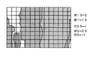
上述した、本方法を用いてウェハ面内のフォーカスバラツキを求めた結果を図10に示す。又、従来の方法で得られたウェハ面内のフォーカスバラツキを求めた結果を図11に示す。従来法の場合、露光量オフセットが原因と思われる系統的な分布になった。図10に示すように、本方法の場合、デフォーカスの分布から露光量変動分が原因と考えられた系統誤差を取り除くことができている。
【0042】
本方法によれば、マスクにフォーカスモニタパターン及び露光量モニタパターンを形成し、レジストに形成された露光量メータの寸法から実効的露光量を測定し、測定された実効的露光量に基づいて変換カーブを補正することによって、最適露光量から大きくずれた設定露光量でも、デフォーカス量の誤差を小さくすることができる。
【0043】
本実施形態においては、露光装置と独立した光学式の線幅測定器を用いて、フォーカス検出マークを測定したが、露光装置自体に内蔵された線幅測定機能やSEM等の光学式以外の測定装置を用いることも可能である。また、フォーカスモニタマークは、線幅測定装置で測定可能なマークであればよく、楔型の形状は、必ずしも先端を鋭利に形成する必要はなく、中央部よりも先端部が短く形成されていればフォーカスモニタマークとしての機能を発揮する。
【0044】
さらにフォーカスモニタパターンのサイズ、ピッチ、及び、半透明膜部分の透過率および露光量モニタパターンの幅、ピッチは、本実施形態で示したものだけに限定されるものではなく、使用する露光条件によって種々変更することで、よりフォーカス検出性能の向上をはかることができる。
【0045】
さらにフォーカスをモニタするマークは先細りパターンにかぎらず、図12に示すようにデバイスパターンを使用することもできる。図12は、マスクの構成を示す図である。図12(a)はマスク全体を示す平面図、図12(b)はフォーカスモニタパターンの構成を示す平面図、図12(c)はデバイス領域102の構成を示す平面図である。図12に示すように、マスク400のフォーカスモニタパターン500が形成されている。フォーカスモニタマークは、第1のパターン領域510と第2のパターン領域520とから構成されている。第1のパターン領域510には、遮光膜203で囲まれた開口511が形成されている。第2のパターン領域520には、半透明膜202で囲まれた開口521が形成されている。そして、デバイス領域102には、遮光膜203で囲まれた開口103が形成されている。このデバイス領域102のパターンは、素子分離パターンである。
【0046】
開口511と開口521との寸法を測定するのではなく、開口521と開口103との寸法をそれぞれ測定し、二つの開口103,521の寸法差からデフォーカス量を求めることができる。なお、デバイスパターンは図に示した素子分離パターンに限らず、様々なパターンを用いることができる。
【0047】
なお、上述したフォーカスモニタパターンと異なり、第1及び第2のパターン領域の何れにも半透明膜を設け、菱形マークの形成により、第1のパターン領域と第2のパターン領域とで異なるの位相差を持たせても良い。
【0048】
例えば、図13に示すように、菱形マーク(第1の開口部)231を形成した第1のパターン領域230では、開口部に露出する基板201を一部堀込む(例えば124nm)ことにより、開口部である菱形マーク231を通過する光に対しその周辺の半透明膜202を通過する光は+90度の位相差を持つことになる。また、菱形マーク(第2の開口部)241を形成した第2のパターン領域240では、開口部に露出する基板201を一部堀込む(例えば372nm)ことにより、開口部である菱形マーク241を通過する光に対しその周辺の半透明膜10を通過する光は−90度の位相差を持つようにしている。
【0049】
また、本実施形態では第1のパターン領域と第2のパターン領域で同じ半透明膜を用い、開口部の透明基板を堀込む量を変えることにより第1のパターン領域と第2のパターン領域とで異なる位相差を持たせたが、この代わりに第1と第2のパターン領域で異なる半透明膜を用いてもよい。
【0050】
また、第1のパターン領域210,230における遮光膜又は半透明膜部と開口部との関係は、逆にしてもよい。即ち、開口部で囲まれて菱形若しくは楔形の遮光膜又は半透明膜で形成されたモニタパターンを有するようにしてもよい。同様に、第2のパターン領域220,240における半透明膜部と開口部との関係も逆にしてもよい。即ち、開口部で囲まれて菱形若しくは楔形の半透明膜で形成されたモニタパターンを有するようにしてもよい。そして、これらの何れの組み合わせを用いても、本実施形態と同様の効果が得られる。
【0051】
本実施形態では、90度の位相差を持った半透明膜のマークを使用したが、位相差は、90度に限定されたものではなく、遮光膜部の楔型マークと、半透明膜部の楔型マークとのベストフォーカス位置変化を生じさせるものであればよい。
【0052】
本実施形態では、位相差フォーカスモニタの変換カーブを一次直線であると仮定したが、これに限られることなく、変換カーブの特性を表すことができれば、種種の関数を用いることができる。
【0053】
また、上記実施形態では、変換カーブの補正の必要/不要を判定するのに、露光量モニタパターンが形成されたマスクを用いていたが、判定時には形成されていないマスクを用いても良い。
【0054】
また、本実施形態ではデバイスのダイシングラインにマークを配置したが、ダイシングラインである必要はなく、デバイス領域の所定の位置に位相差フォーカスモニタマークおよび露光量モニタマークを配置して使用することや、これらのマークを含んだテストマスクを使用することによってもフォーカスをモニタすることができる。
【0055】
なお、本発明は、上記実施形態に限定されるものではなく、実施段階ではその要旨を逸脱しない範囲で種々に変形することが可能である。更に、上記実施形態には種々の段階の発明が含まれており、開示される複数の構成要件における適宜な組み合わせにより種々の発明が抽出され得る。例えば、実施形態に示される全構成要件から幾つかの構成要件が削除されても、発明が解決しようとする課題の欄で述べた課題が解決でき、発明の効果の欄で述べられている効果が得られる場合には、この構成要件が削除された構成が発明として抽出され得る。
【0056】
【発明の効果】
以上説明したように本発明によれば、マスクにフォーカスモニタパターン及び露光量モニタパターンを形成し、ウエハ上に形成された露光量メータの寸法から実効的露光量を測定し、測定された実効的露光量に基づいて変換カーブを補正することによって、最適露光量から大きくずれた設定露光量でも、デフォーカス量の誤差を小さくすることができる。
【図面の簡単な説明】
【図1】 本発明の一実施形態に係わるマスクの概略構成を示す平面図。
【図2】 フォーカスモニタの構成を示す平面図。
【図3】 菱形マーク221及び菱形マーク221の長辺の寸法差とデフォーカス量との関係の露光量量依存性を示す。
【図4】 露光量モニタパターンの構成を示す平面図。
【図5】 露光量メータの長さと露光量の関係を示す図。
【図6】 本発明の一実施形態に係わるデフォーカス量の測定方法の一部を示すフローチャート。
【図7】 寸法差とデフォーカス量の関係(変換カーブ)の露光量依存性を示す図。
【図8】 露光量に対する係数bを示す図。
【図9】 本発明の一実施形態に係わるデフォーカス量測定方法を示すフローチャートである。
【図10】 本方法を用いてウェハ面内のフォーカスバラツキを求めた結果を示す平面図。
【図11】 従来方法を用いてウェハ面内のフォーカスバラツキを求めた結果を示す平面図。
【図12】 マスクの構成の変形例を示す平面図。
【図13】 フォーカスモニタパターンの構成の変形例を示す図。
【符号の説明】
100…マスク,101…ダイシングライン,102…デバイス領域,200…フォーカスモニタパターン,201…透明基板,202…半透明膜,203…遮光膜,210…第1のパターン領域,211…菱形マーク,220…第2のパターン領域,221…菱形マーク[0001]
BACKGROUND OF THE INVENTION
The present invention relates to a focus monitor method and a mask suitable for setting a focus condition in a projection exposure apparatus with respect to the manufacture of a semiconductor element, a liquid crystal display element and the like.
[0002]
[Prior art]
As a method for easily and accurately measuring the amount of focus deviation, a focus monitor mask on which a focus change pattern (focus monitor pattern) can be detected is exposed, and the line width of the monitor mark after transfer is determined as the line width. There is a method of measuring using a measuring device (optical line width measuring instrument, SEM, etc.) or a line width measuring function built in the exposure apparatus itself, and obtaining a focus fluctuation amount from the result (for example, Patent Document 1).
[0003]
With the focus monitor pattern described in
[0004]
[Patent Document 1]
JP 2001-1000039 A
[0005]
[Problems to be solved by the invention]
As described above, when exposure is performed with an exposure amount greatly deviated from the optimum exposure amount of the focus monitor pattern, there is a problem in that the conversion curve has an exposure amount dependency and a required defocus amount error increases.
[0006]
SUMMARY OF THE INVENTION An object of the present invention is to provide a focus monitor method and a mask that can reduce a required defocus amount error even if a focus monitor pattern is exposed with an exposure amount greatly deviated from an optimum exposure amount.
[0007]
[Means for Solving the Problems]
The present invention is configured as follows to achieve the above object.
[0008]
(1) In the focus monitoring method according to an example of the present invention, a focus monitor pattern whose dimension changes according to the defocus amount is formed on the wafer, and the size changes according to the effective exposure amount. A step of preparing a mask on which an exposure amount monitor pattern is formed to form an exposure amount meter on the wafer; a step of obtaining a relationship between the dimension of the focus monitor mark and the defocus amount; and a relationship of the exposure amount; A step of forming a focus monitor pattern and an exposure meter on the wafer using the mask; a step of measuring the dimension of the exposure meter to determine an effective exposure amount; From the relationship between the size of the focus monitor mark and the defocus amount and the relationship between the exposure amount and the effective exposure amount, A step of obtaining a relationship between the size of the focus monitor mark and the defocus amount, a step of measuring the size of the focus monitor mark, a focus according to the measured size of the focus monitor mark, and the effective exposure amount And a step of obtaining a defocus amount based on a relationship between the dimension of the monitor mark and the defocus amount.
[0009]
(2) A focus monitoring method according to an example of the present invention includes a step of preparing a first mask on which a focus monitor pattern for forming a focus monitor mark whose dimension changes according to a defocus amount is formed on a wafer; For a plurality of exposure amounts, a step of obtaining a relationship between the dimension of the focus monitor mark and the defocus amount, and a variation amount corresponding to the exposure amount of the relationship between the obtained dimension of the focus monitor mark and the defocus amount are obtained. When the step and the obtained variation amount are larger than a predetermined value, the size varies depending on the relationship between the focus monitor mark dimension and the defocus amount, the relationship between the exposure amount and the defocus amount. The focus monitor pattern that forms the focus monitor mark on the wafer and the size according to the effective exposure amount Preparing a second mask dose monitor pattern is arranged to form the exposure meter that of on the wafer, Determining the relationship between the amount of exposure meter and the amount of exposure; Forming a focus monitor mark and an exposure meter on the wafer using the second mask; measuring a size of the exposure meter to determine an effective exposure amount; The relationship between the effective exposure amount, the relationship between the focus monitor mark size and the defocus amount, and the exposure amount, and the relationship between the focus monitor mark size and the defocus amount according to the effective exposure amount. A step of determining, a step of measuring the size of the focus monitor mark, a size of the measured focus monitor mark, and a relationship between the size of the focus monitor mark and the defocus amount according to the effective exposure amount And a step of obtaining a defocus amount.
[0010]
(3) A mask according to an example of the present invention is surrounded by a device region in which a device pattern is formed and a first opening, and is formed by a first translucent film or surrounded by a first translucent film. And having at least one monitor pattern which is formed by the first opening and gives a predetermined phase difference to the exposure light passing through the semi-transparent film with respect to the exposure light passing through the first opening. For focus monitor A first pattern region and a second semi-transparent film surrounded by the second opening, or a second opening surrounded by the second semi-transparent film and the second opening The exposure light passing through the second translucent film has at least one monitor pattern that gives a phase difference different from that of the first pattern region to the exposure light passing through the second translucent film For focus monitor The second pattern region and a plurality of blocks in which a light shielding portion and a light transmitting portion are arranged in one direction within a certain width p that cannot be resolved by the projection exposure apparatus are intermittently or continuously provided in the first pattern region. A pattern in which the dimensional ratio between the light shielding portion and the light transmitting portion of the block changes monotonously in the one direction. For exposure monitor A third pattern region, and one of the first pattern region and the second pattern region is formed at least in the device region.
[0011]
(4) A mask according to an example of the present invention is surrounded by a device region in which a device pattern is formed and a light shielding portion, and is formed by a first opening portion or surrounded by a first opening portion. Having at least one monitor pattern formed 1st for focus monitor The pattern region and the semi-transparent film are surrounded by a second opening, or the second opening is surrounded by a semi-transparent film, and the exposure light passes through the second opening. And at least one monitor pattern that gives a predetermined phase difference to the exposure light passing through the translucent film For focus monitor The second pattern region and a plurality of blocks in which a light shielding portion and a light transmitting portion are arranged in one direction within a certain width p that cannot be resolved by the projection exposure apparatus are intermittently or continuously provided in the first pattern region. Arranged in a direction, and the dimensional ratio between the light shielding part and the light transmitting part of the block changes monotonously in the one direction For exposure monitor A third pattern region, and one of the first pattern region and the second pattern region is formed at least in the device region.
[0012]
DETAILED DESCRIPTION OF THE INVENTION
Embodiments of the present invention will be described below with reference to the drawings.
[0013]
FIG. 1 is a plan view showing a schematic configuration of a mask according to an embodiment of the present invention. As shown in FIG. 1, a
[0014]
The configuration of the focus monitor pattern will be described with reference to FIG. 2A is a plan view showing the configuration of the focus monitor pattern, and FIG. 2B is a cross-sectional view taken along the line AA ′ of FIG. 2A. 201 in the figure is a transparent substrate such as glass, 202 is SiO 2 A semi-transparent film such as 203, and a
[0015]
In the
[0016]
FIG. 3 shows the exposure amount dependency of the relationship between the dimensional difference of the long side of the focus monitor mark formed by transferring the
[0017]
In FIG. 2A, two types of focus monitor patterns having different directions are formed. This is because, when the aberration of the optical system of the exposure apparatus is large, the size of the mark formed may differ depending on the direction of the pattern. In such a case, the average of the defocus amounts obtained with the respective focus monitor marks is set as the defocus amount. As a result, the influence of the aberration of the optical system can be suppressed.
[0018]
Next, the configuration of the exposure amount monitor pattern will be described with reference to FIG. FIG. 4 is a plan view showing the configuration of the exposure amount monitor pattern.
As shown in FIG. 4, the exposure
[0019]
When this exposure amount monitor pattern is irradiated with illumination light, the light intensity distribution of the diffracted light of the exposure amount monitor pattern on the substrate surface is monotonously decreased or monotonically increased independent of the focus position.
[0020]
Consider a case where a mask whose effective exposure amount is to be monitored is set in an exposure apparatus having a numerical aperture NA, a coherent factor σ, and a wavelength λ. The condition of the width p (wafer dimension) of the block that is not resolved by this apparatus is based on diffraction theory.
[Equation 3]
[0021]
By forming a photoresist film on the substrate, a latent image (exposure meter) corresponding to the gradient distribution of the irradiation dose independent of the focus state is formed on the photoresist film. The exposure amount is measured by measuring the length of one direction of the latent image formed on the photoresist film or the pattern obtained by developing the photoresist film. FIG. 5 shows the relationship between the length of the exposure meter and the exposure amount.
[0022]
The measured dimensions of the focus monitor mark, the defocus amount, and the exposure amount can be expressed by the following equations.
[0023]
[Expression 4]
![]()
Therefore, when the dimension of the focus monitor pattern to be measured varies depending on the exposure amount, the conversion curve of the focus monitor pattern is first removed by using the effective exposure amount obtained from the exposure amount meter, and the calculated defocus amount is calculated. It is possible to remove exposure dose dependency.
[0024]
L: Dimensional difference between the mark in the
Therefore, when the dimension of the focus monitor pattern to be measured varies depending on the exposure amount, the conversion curve of the focus monitor pattern is first removed by using the effective exposure amount obtained from the exposure amount meter, and the calculated defocus amount is calculated. It is possible to remove exposure dose dependency.
[0025]
First, it is determined whether or not the set exposure amount needs to be corrected for the conversion curve in accordance with the effective exposure amount. When the conversion curve needs to be corrected, it is necessary to obtain the relationship between the effective exposure amount and the conversion curve. This method will be described with reference to FIG. FIG. 6 is a flowchart showing a part of the defocus amount measuring method according to the embodiment of the present invention.
[0026]
The photoresist film on the wafer is exposed to the pattern formed on the mask with a plurality of set exposure amounts, and the dependency of the conversion curve on the exposure amount is examined (step S101).
[0027]
Specifically, 30 mJ / cm 2 The exposure was performed while changing from -10% to + 10%, centering on the set exposure amount. FIG. 7 shows the exposure amount dependency of the relationship (conversion curve) between the dimensional difference and the defocus amount. Graph shows exposure 30mJ / cm 2 -10%, -5%, -1%, 0% (30 mJ / cm) 2 ), + 1%, + 5%, and + 10%, the relationship between the dimensional difference and defocus is shown. From the results shown in FIG. 7, it can be seen that the conversion curve varies depending on the set exposure amount (each straight line in the graph varies).
[0028]
The conditions for obtaining the conversion curve are shown below. A coating-type antireflection film having a thickness of 60 nm and a chemically amplified positive photoresist film having a thickness of 0.4 μm are formed on the wafer. The antireflection film and the photoresist film are formed using a spin coating method.
[0029]
The reduction ratio of the projection optical system of the exposure apparatus is 1/4, the exposure wavelength is 248 nm, NA = 0.6, the coherence factor σ = 0.75, and the annular zone shielding ratio ε = 0.67. In the case of this exposure apparatus, an exposure amount monitor pattern having a pitch of 0.19 μm, a width of 2 μm, and a space dimension continuously changing by 0.625 nm in terms of wafer was used.
[0030]
Next, the exposed wafer is post-exposure baked (PEB) at 100 ° C. for 90 seconds, and then developed with a 0.21 normal alkali developer for 60 seconds.
[0031]
Next, two types of wedge-shaped patterns on the processed wafer are measured by an optical line width measuring device, and the X-axis in the wedge-shaped pattern formed by transferring the marks of the
[0032]
Next, after obtaining the exposure amount dependency of the conversion curve, the variation in the defocus amount due to the change in the exposure amount is measured (step S102). As shown in FIG. 7, the conversion curve at each exposure amount is approximated by a linear expression y = ax + b. Then, the variation of the y-axis intercept (b) of each approximate expression is obtained. Here, the maximum value bmax−the minimum value bmin is obtained. Divide the variation of the y-axis intercept by the slope a. The obtained value is a variation in defocus amount due to a change in exposure amount.
[0033]
It is determined whether the obtained variation is less than the specification value (step S103). In the case of this embodiment, the spec value is 10 nm. Further, in the case of the conversion curve shown in FIG. 7, the variation was 50 nm.
[0034]
If the variation is less than the specification value (for example, FIG. 3), one of the obtained conversion curves is determined as a conversion curve with the exposure amount (step S104).
[0035]
When the variation is larger than the specification value, the relationship between the conversion curve and the exposure amount is obtained (step S105). Here, the exposure dose dependency of the coefficient b obtained previously is obtained. The coefficient b with respect to the exposure amount is shown in FIG. The coefficient b for the exposure amount is approximated by a quadratic function. In the case of FIG. 8, the quadratic function is y = 0.0028x. 2 -0.2081x + 4.4479.
As described above, the necessity for correction of the conversion curve and the relationship between the effective exposure amount and the conversion curve are obtained.
[0036]
Next, a method of measuring the defocus amount when the variation is larger than the spec value and the conversion curve needs to be corrected according to the effective exposure amount will be described with reference to FIG. FIG. 9 is a flowchart showing a defocus amount measuring method according to an embodiment of the present invention.
[0037]
An actual wafer is exposed using the above-described mask to form a focus monitor mark and an exposure meter (step S201). The exposure / development conditions are the same as those described above.
[0038]
Next, the dimensions of the two types of focus monitor marks and the exposure meter are measured (step S202). The dimensional difference between the two types of focus monitor marks is obtained. An effective exposure amount is obtained from the dimension of the exposure amount meter (step S203).
[0039]
The obtained effective exposure amount is substituted into x of the above-described function for calculation to obtain a coefficient (step S204). Next, the conversion curve is moved in parallel in the y direction so that the intercept of the conversion curve is equal to the calculated coefficient, and the conversion curve is corrected (step S205). Although a plurality of conversion curves existed in FIG. 7, here, the set exposure amount is 30 mJ / cm. 2 Move the conversion curve at.
[0040]
Next, the defocus amount is obtained using the dimensional difference of the focus monitor mark and the corrected conversion curve (step S206).
[0041]
FIG. 10 shows the result of obtaining the focus variation within the wafer surface by using the above-described method. Further, FIG. 11 shows the result of obtaining the focus variation in the wafer surface obtained by the conventional method. In the case of the conventional method, the systematic distribution is considered to be caused by the exposure amount offset. As shown in FIG. 10, in the case of this method, the systematic error considered to be caused by the exposure amount fluctuation can be removed from the defocus distribution.
[0042]
According to this method, a focus monitor pattern and an exposure amount monitor pattern are formed on the mask, an effective exposure amount is measured from the dimension of the exposure amount meter formed on the resist, and conversion is performed based on the measured effective exposure amount. By correcting the curve, it is possible to reduce the error of the defocus amount even with the set exposure amount greatly deviating from the optimum exposure amount.
[0043]
In the present embodiment, the focus detection mark is measured using an optical line width measuring device independent of the exposure apparatus. However, the line width measurement function built in the exposure apparatus itself and measurements other than optical such as SEM are performed. It is also possible to use a device. The focus monitor mark may be any mark that can be measured by a line width measuring device. The wedge shape does not necessarily have a sharp tip, and the tip is shorter than the center. It will function as a focus monitor mark.
[0044]
Further, the size and pitch of the focus monitor pattern, and the transmissivity of the translucent film portion and the width and pitch of the exposure amount monitor pattern are not limited to those shown in the present embodiment, but depend on the exposure conditions used. Various changes can be made to further improve the focus detection performance.
[0045]
Furthermore, the mark for monitoring the focus is not limited to the tapered pattern, and a device pattern can also be used as shown in FIG. FIG. 12 is a diagram showing the configuration of the mask. 12A is a plan view showing the entire mask, FIG. 12B is a plan view showing the configuration of the focus monitor pattern, and FIG. 12C is a plan view showing the configuration of the
[0046]
Rather than measuring the dimensions of the
[0047]
Unlike the focus monitor pattern described above, a semi-transparent film is provided in each of the first and second pattern areas, and the first pattern area and the second pattern area differ depending on the formation of the rhombus marks. You may give a phase difference.
[0048]
For example, as shown in FIG. 13, in the
[0049]
In the present embodiment, the same pattern is used in the first pattern region and the second pattern region, and the first pattern region and the second pattern region are changed by changing the amount of the transparent substrate in the opening. However, different translucent films may be used in the first and second pattern regions instead.
[0050]
In addition, the relationship between the light shielding film or translucent film portion and the opening in the
[0051]
In this embodiment, a semi-transparent film mark having a phase difference of 90 degrees is used. However, the phase difference is not limited to 90 degrees, and the wedge-shaped mark of the light shielding film part and the semi-transparent film part are used. Any one that causes a change in the best focus position with the wedge-shaped mark may be used.
[0052]
In this embodiment, it is assumed that the conversion curve of the phase difference focus monitor is a linear line. However, the present invention is not limited to this, and various functions can be used as long as the characteristics of the conversion curve can be expressed.
[0053]
In the above embodiment, the mask on which the exposure amount monitor pattern is formed is used to determine whether the correction of the conversion curve is necessary. However, a mask that is not formed at the time of determination may be used.
[0054]
In this embodiment, the mark is arranged on the dicing line of the device. However, the mark need not be a dicing line, and the phase difference focus monitor mark and the exposure amount monitor mark may be arranged and used at predetermined positions in the device area. The focus can also be monitored by using a test mask including these marks.
[0055]
In addition, this invention is not limited to the said embodiment, In the implementation stage, it can change variously in the range which does not deviate from the summary. Further, the above embodiments include inventions at various stages, and various inventions can be extracted by appropriately combining a plurality of disclosed constituent elements. For example, even if some constituent requirements are deleted from all the constituent requirements shown in the embodiment, the problem described in the column of the problem to be solved by the invention can be solved, and the effect described in the column of the effect of the invention Can be obtained as an invention.
[0056]
【The invention's effect】
As described above, according to the present invention, the focus monitor pattern and the exposure monitor pattern are formed on the mask, the effective exposure is measured from the dimensions of the exposure meter formed on the wafer, and the measured effective By correcting the conversion curve based on the exposure amount, an error in the defocus amount can be reduced even with a set exposure amount greatly deviating from the optimum exposure amount.
[Brief description of the drawings]
FIG. 1 is a plan view showing a schematic configuration of a mask according to an embodiment of the present invention.
FIG. 2 is a plan view showing a configuration of a focus monitor.
FIG. 3 shows the exposure amount dependency of the relationship between the dimensional difference between the long sides of the
FIG. 4 is a plan view showing a configuration of an exposure amount monitor pattern.
FIG. 5 is a view showing the relationship between the length of an exposure meter and the exposure amount.
FIG. 6 is a flowchart showing a part of a defocus amount measurement method according to an embodiment of the present invention.
FIG. 7 is a diagram showing the exposure dose dependency of the relationship (conversion curve) between the dimensional difference and the defocus amount.
FIG. 8 is a diagram showing a coefficient b with respect to an exposure amount.
FIG. 9 is a flowchart showing a defocus amount measuring method according to an embodiment of the present invention.
FIG. 10 is a plan view showing the result of obtaining the focus variation in the wafer surface using this method.
FIG. 11 is a plan view showing a result of obtaining a focus variation in a wafer surface using a conventional method.
FIG. 12 is a plan view showing a modification of the configuration of the mask.
FIG. 13 is a diagram showing a modification of the configuration of the focus monitor pattern.
[Explanation of symbols]
DESCRIPTION OF
Claims (11)
前記フォーカスモニタマークの寸法とデフォーカス量との関係と、露光量との関係を求める工程と、
前記マスクを用いてフォーカスモニタパターン及び露光量メータをウェハ上に形成する工程と、
前記露光量メータの寸法を測定し、実効的な露光量を求める工程と、
求められた実効的な露光量と、前記フォーカスモニタマークの大きさとデフォーカス量との関係と露光量との関係とから、前記実効的な露光量に応じた前記フォーカスモニタマークの寸法とデフォーカス量との関係を求める工程と、
前記フォーカスモニタマークの寸法を測定する工程と、
測定されたフォーカスモニタマークの寸法と、前記実効的な露光量に応じたフォーカスモニタマークの寸法とデフォーカス量との関係に基づいてデフォーカス量を求める工程とを含むことを特徴とするフォーカスモニタ方法。A focus monitor pattern for forming on the wafer a focus monitor mark whose size changes according to the defocus amount, and an exposure amount monitor pattern for forming an exposure meter whose size changes according to the effective exposure amount on the wafer Preparing a mask on which is disposed,
Determining the relationship between the dimension of the focus monitor mark and the defocus amount, and the exposure amount;
Forming a focus monitor pattern and an exposure meter on the wafer using the mask;
Measuring the dimensions of the exposure meter to determine an effective exposure amount; and
From the obtained effective exposure amount, the relationship between the focus monitor mark size and the defocus amount, and the exposure amount, the size and defocus of the focus monitor mark according to the effective exposure amount A process for determining the relationship with the quantity;
Measuring the dimensions of the focus monitor mark;
And a step of obtaining a defocus amount based on a relationship between the measured size of the focus monitor mark and the size of the focus monitor mark corresponding to the effective exposure amount and the defocus amount. Method.
複数の露光量について、前記フォーカスモニタマークの寸法とデフォーカス量との関係を求める工程と、
求められた前記フォーカスモニタマークの寸法とデフォーカス量との関係の露光量に応じたバラツキ量を求める工程と、
求められたバラツキ量が所定値より大きい場合、前記フォーカスモニタマークの寸法とデフォーカス量との関係と、露光量との関係を求める工程と、
デフォーカス量に応じて寸法が変化するフォーカスモニタマークをウェハ上に形成するフォーカスモニタパターン、及び実効的な露光量に応じて寸法が変化する露光量メータを前記ウェハ上に形成する露光量モニタパターンが配置された第2のマスクを用意する工程と、
前記露光量メータの大きさと、露光量との関係を求める工程と、
前記第2のマスクを用いてフォーカスモニタマーク及び露光量メータをウェハ上に形成する工程と、
前記露光量メータの大きさを測定し、実効的な露光量を求める工程と、
求められた実効的な露光量と、前記フォーカスモニタマークの大きさとデフォーカス量との関係と露光量との関係とから、前記実効的な露光量に応じた前記フォーカスモニタマークの寸法とデフォーカス量との関係を求める工程と、
前記フォーカスモニタマークの寸法を測定する工程と、
測定されたフォーカスモニタマークの寸法と、前記実効的な露光量に応じたフォーカスモニタマークの寸法とデフォーカス量との関係に基づいてデフォーカス量を求める工程とを含むことを特徴とするフォーカスモニタ方法。Preparing a first mask on which a focus monitor pattern for forming on the wafer a focus monitor mark whose dimension changes in accordance with a defocus amount;
Obtaining a relationship between the size of the focus monitor mark and the defocus amount for a plurality of exposure amounts;
Obtaining a variation amount according to the exposure amount of the relationship between the determined focus monitor mark dimension and the defocus amount; and
When the obtained variation amount is larger than a predetermined value, the step of obtaining the relationship between the dimension of the focus monitor mark and the defocus amount, and the exposure amount;
A focus monitor pattern for forming on the wafer a focus monitor mark whose size changes according to the defocus amount, and an exposure amount monitor pattern for forming an exposure meter whose size changes according to the effective exposure amount on the wafer Preparing a second mask on which is disposed;
Determining the relationship between the amount of exposure meter and the amount of exposure;
Forming a focus monitor mark and an exposure meter on the wafer using the second mask;
Measuring the size of the exposure meter and obtaining an effective exposure amount; and
From the obtained effective exposure amount, the relationship between the focus monitor mark size and the defocus amount, and the exposure amount, the size and defocus of the focus monitor mark according to the effective exposure amount A process for determining the relationship with the quantity;
Measuring the dimensions of the focus monitor mark;
And a step of obtaining a defocus amount based on a relationship between the measured size of the focus monitor mark and the size of the focus monitor mark corresponding to the effective exposure amount and the defocus amount. Method.
半透明膜で囲まれて、第2の開口部で形成、または第2の開口部で囲まれて半透明膜で形成され,第2の開口部を通過する露光光に対して半透明膜を通過する露光光に所定の位相差を与える少なくとも一つのモニタパターンを有する第2のパターン領域とを具備し、
前記フォーカスモニタ用マークの大きさとデフォーカスとの関係を求める際、第1のパターン領域のモニタパターンの寸法と第2のパターン領域のパターンの寸法との差、または比を求めることを特徴とする請求項1又は2に記載のフォーカスモニタ方法。The focus monitor pattern is surrounded by a light shielding portion and formed by a first opening, or a first pattern region having at least one monitor pattern surrounded by the first opening and formed by a light shielding portion; Surrounded by a semi-transparent film and formed by the second opening, or surrounded by the second opening and formed by a semi-transparent film, the semi-transparent film is formed with respect to the exposure light passing through the second opening. A second pattern region having at least one monitor pattern that gives a predetermined phase difference to the passing exposure light;
When obtaining the relationship between the size of the focus monitor mark and the defocus, the difference or ratio between the monitor pattern size of the first pattern region and the pattern size of the second pattern region is obtained. The focus monitoring method according to claim 1 or 2.
第2の開口部で囲まれて第2の半透明膜で形成、または第2の半透明膜で囲まれて第2の開口部で形成され,第2の開口部を通過する露光光に対して第2の半透明膜を通過する露光光に第1のパターン領域とは異なる位相差を与える少なくとも一つのモニタパターンを有する第2のパターン領域とを具備し、
前記フォーカスモニタ用マークの大きさとデフォーカスとの関係を求める際、第1のパターン領域のモニタパターンの寸法と第2のパターン領域のパターンの寸法との差L、または比を求めることを特徴とする請求項1又は2に記載のフォーカスモニタ方法。The focus monitor pattern is surrounded by a first opening and formed by a first semi-transparent film, or is surrounded by a first semi-transparent film and formed by a first opening. A first pattern region having at least one monitor pattern that gives a predetermined phase difference to the exposure light passing through the semi-transparent film with respect to the exposure light passing through the portion, and a second half An exposure light that is formed of a transparent film or surrounded by a second semi-transparent film and formed by a second opening, and that passes through the second semi-transparent film with respect to the exposure light that passes through the second opening. A second pattern region having at least one monitor pattern that provides a phase difference different from the first pattern region;
When obtaining the relationship between the size of the focus monitor mark and the defocus, the difference L or the ratio between the monitor pattern dimension of the first pattern area and the pattern dimension of the second pattern area is obtained. The focus monitoring method according to claim 1 or 2.
前記計測工程では
前記ブロックの配列方向の長さを測定することを特徴とする請求項6に記載のフォーカスモニタ方法。When the wavelength of the exposure apparatus for exposing the mask is λ, the numerical aperture on the wafer side is NA, and the coherence factor σ, the pitch P on the wafer is
The focus monitoring method according to claim 6, wherein in the measurement step, the length of the blocks in the arrangement direction is measured.
第1の開口部で囲まれて、第1の半透明膜で形成、または第1の半透明膜で囲まれて第1の開口部で形成され、第1の開口部を通過する露光光に対して半透明膜を通過する露光光に所定の位相差を与える少なくとも一つのモニタパターンを有するフォーカスモニタ用の第1のパターン領域と、
第2の開口部で囲まれて第2の半透明膜で形成、または第2の半透明膜で囲まれて第2の開口部で形成され、第2の開口部を通過する露光光に対して第2の半透明膜を通過する露光光に第1のパターン領域とは異なる位相差を与える少なくとも一つのモニタパターンを有するフォーカスモニタ用の第2のパターン領域と、
前記投影露光装置で解像することができない一定幅p内に遮光部と透光部とが一方向に配列された複数のブロックが断続的、または連続的に前記一方向に配列され、該ブロックの遮光部と透光部との寸法比が前記一方向に単調に変化するパターンを有する露光量モニ タ用の第3のパターン領域とを具備し、
前記第1のパターン領域又は第2のパターン領域の一方は、少なくとも前記デバイス領域に形成されていることを特徴とするマスク。A device region in which a device pattern is formed; and
Exposure light that is surrounded by the first opening and formed by the first semi-transparent film, or is formed by the first opening and surrounded by the first semi-transparent film, and passes through the first opening. A first pattern region for a focus monitor having at least one monitor pattern that gives a predetermined phase difference to the exposure light passing through the translucent film;
For exposure light that is surrounded by the second opening and formed by the second semi-transparent film, or that is surrounded by the second semi-transparent film and formed by the second opening, and passes through the second opening. A second pattern region for a focus monitor having at least one monitor pattern that gives the exposure light passing through the second translucent film a phase difference different from that of the first pattern region;
A plurality of blocks in which light-shielding portions and light-transmitting portions are arranged in one direction within a certain width p that cannot be resolved by the projection exposure apparatus are intermittently or continuously arranged in the one direction. dimensional ratio between the light shielding portion and the transparent portion is provided with a third pattern regions for exposure monitor having monotonically changing pattern in the one direction,
One of the first pattern region or the second pattern region is formed in at least the device region.
遮光部で囲まれて、第1の開口部で形成、または第1の開口部で囲まれて遮光部で形成された少なくとも1つのモニタパターンを有するフォーカスモニタ用の第1のパターン領域と、
半透明膜で囲まれて、第2の開口部で形成、または第2の開口部で囲まれて半透明膜で形成され,第2の開口部を通過する露光光に対して半透明膜を通過する露光光に所定の位相差を与える少なくとも一つのモニタパターンを有するフォーカスモニタ用の第2のパターン領域と、
前記投影露光装置で解像することができない一定幅p内に遮光部と透光部とが一方向に配列された複数のブロックが断続的、または連続的に前記一方向に配列され、該ブロックの遮光部と透光部との寸法比が前記一方向に単調に変化するパターンを有する露光量モニタ用の第3のパターン領域とを具備し、
前記第1のパターン領域又は第2のパターン領域の一方は、少なくとも前記デバイス領域に形成されていることを特徴とするマスク。A device region in which a device pattern is formed; and
A first pattern region for a focus monitor having at least one monitor pattern surrounded by the light shielding portion and formed by the first opening, or surrounded by the first opening and formed by the light shielding portion;
Surrounded by a semi-transparent film and formed by the second opening, or surrounded by the second opening and formed by a semi-transparent film, the semi-transparent film is formed with respect to the exposure light passing through the second opening. A second pattern region for a focus monitor having at least one monitor pattern that gives a predetermined phase difference to the passing exposure light;
A plurality of blocks in which light-shielding portions and light-transmitting portions are arranged in one direction within a certain width p that cannot be resolved by the projection exposure apparatus are intermittently or continuously arranged in the one direction. A third pattern region for exposure amount monitoring having a pattern in which the dimensional ratio of the light shielding portion to the light transmitting portion monotonously changes in the one direction,
One of the first pattern region or the second pattern region is formed in at least the device region.
Priority Applications (2)
| Application Number | Priority Date | Filing Date | Title |
|---|---|---|---|
| JP2003046236A JP3854234B2 (en) | 2003-02-24 | 2003-02-24 | Focus monitor method and mask |
| US10/784,277 US7250235B2 (en) | 2003-02-24 | 2004-02-24 | Focus monitor method and mask |
Applications Claiming Priority (1)
| Application Number | Priority Date | Filing Date | Title |
|---|---|---|---|
| JP2003046236A JP3854234B2 (en) | 2003-02-24 | 2003-02-24 | Focus monitor method and mask |
Publications (2)
| Publication Number | Publication Date |
|---|---|
| JP2004259765A JP2004259765A (en) | 2004-09-16 |
| JP3854234B2 true JP3854234B2 (en) | 2006-12-06 |
Family
ID=33112831
Family Applications (1)
| Application Number | Title | Priority Date | Filing Date |
|---|---|---|---|
| JP2003046236A Expired - Fee Related JP3854234B2 (en) | 2003-02-24 | 2003-02-24 | Focus monitor method and mask |
Country Status (2)
| Country | Link |
|---|---|
| US (1) | US7250235B2 (en) |
| JP (1) | JP3854234B2 (en) |
Families Citing this family (15)
| Publication number | Priority date | Publication date | Assignee | Title |
|---|---|---|---|---|
| JP4015079B2 (en) * | 2003-07-18 | 2007-11-28 | 株式会社東芝 | Reticle, exposure apparatus inspection system, exposure apparatus inspection method, and reticle manufacturing method |
| JP4588368B2 (en) * | 2004-06-15 | 2010-12-01 | 富士通セミコンダクター株式会社 | Exposure measurement method and apparatus, and semiconductor device manufacturing method |
| US7642019B2 (en) * | 2005-04-15 | 2010-01-05 | Samsung Electronics Co., Ltd. | Methods for monitoring and adjusting focus variation in a photolithographic process using test features printed from photomask test pattern images; and machine readable program storage device having instructions therefore |
| US7379170B2 (en) * | 2005-05-02 | 2008-05-27 | Invarium, Inc. | Apparatus and method for characterizing an image system in lithography projection tool |
| WO2007029315A1 (en) * | 2005-09-06 | 2007-03-15 | Fujitsu Limited | Pattern transfer mask, focus error measurement method and apparatus, and method of fabricating semiconductor device |
| JP4997748B2 (en) * | 2005-11-28 | 2012-08-08 | 凸版印刷株式会社 | Photomask transfer simulation method having focus monitor mark |
| TWI383273B (en) | 2007-11-20 | 2013-01-21 | Asml Netherlands Bv | Method of measuring focus of a lithographic projection apparatus and method of calibrating a lithographic projection apparatus |
| EP2131243B1 (en) | 2008-06-02 | 2015-07-01 | ASML Netherlands B.V. | Lithographic apparatus and method for calibrating a stage position |
| JP5584689B2 (en) | 2008-10-06 | 2014-09-03 | エーエスエムエル ネザーランズ ビー.ブイ. | Lithographic focus and dose measurement using a two-dimensional target |
| US9411223B2 (en) | 2012-09-10 | 2016-08-09 | Globalfoundries Inc. | On-product focus offset metrology for use in semiconductor chip manufacturing |
| US9411249B2 (en) | 2013-09-23 | 2016-08-09 | Globalfoundries Inc. | Differential dose and focus monitor |
| US9383657B2 (en) * | 2014-03-03 | 2016-07-05 | Taiwan Semiconductor Manufacturing Company, Ltd. | Method and structure for lithography processes with focus monitoring and control |
| US9760017B2 (en) | 2015-03-20 | 2017-09-12 | Toshiba Memory Corporation | Wafer lithography equipment |
| CN106154755B (en) * | 2015-04-03 | 2018-03-23 | 中芯国际集成电路制造(上海)有限公司 | The detection method of photoresist thickness abnormity |
| US10197922B2 (en) | 2015-08-06 | 2019-02-05 | Kla-Tencor Corporation | Focus metrology and targets which utilize transformations based on aerial images of the targets |
Family Cites Families (10)
| Publication number | Priority date | Publication date | Assignee | Title |
|---|---|---|---|---|
| US6440616B1 (en) * | 1999-09-28 | 2002-08-27 | Kabushiki Kaisha Toshiba | Mask and method for focus monitoring |
| JP2001100392A (en) | 1999-09-28 | 2001-04-13 | Toshiba Corp | Focus monitor mask and focus monitor method |
| JP3297423B2 (en) * | 2000-08-09 | 2002-07-02 | 株式会社東芝 | Focus test mask and method of measuring focus and aberration using the same |
| KR100455684B1 (en) * | 2001-01-24 | 2004-11-06 | 가부시끼가이샤 도시바 | Focus monitoring method, exposure apparatus and mask for exposure |
| JP2003007598A (en) * | 2001-06-25 | 2003-01-10 | Mitsubishi Electric Corp | Focus monitor method, focus monitor device, and semiconductor device manufacturing method |
| JP2003057800A (en) * | 2001-08-09 | 2003-02-26 | Mitsubishi Electric Corp | Focus monitor method, focus monitor device, and semiconductor device manufacturing method |
| JP3605064B2 (en) * | 2001-10-15 | 2004-12-22 | 株式会社ルネサステクノロジ | Focus monitor photomask, focus monitor method, focus monitor device and device manufacturing method |
| JP3850746B2 (en) * | 2002-03-27 | 2006-11-29 | 株式会社東芝 | Photomask, focus monitor method, exposure amount monitor method, and semiconductor device manufacturing method |
| US6974653B2 (en) * | 2002-04-19 | 2005-12-13 | Nikon Precision Inc. | Methods for critical dimension and focus mapping using critical dimension test marks |
| US6777145B2 (en) * | 2002-05-30 | 2004-08-17 | Chartered Semiconductor Manufacturing Ltd. | In-line focus monitor structure and method using top-down SEM |
-
2003
- 2003-02-24 JP JP2003046236A patent/JP3854234B2/en not_active Expired - Fee Related
-
2004
- 2004-02-24 US US10/784,277 patent/US7250235B2/en not_active Expired - Fee Related
Also Published As
| Publication number | Publication date |
|---|---|
| US7250235B2 (en) | 2007-07-31 |
| JP2004259765A (en) | 2004-09-16 |
| US20040224242A1 (en) | 2004-11-11 |
Similar Documents
| Publication | Publication Date | Title |
|---|---|---|
| JP3949853B2 (en) | Control method for exposure apparatus and control method for semiconductor manufacturing apparatus | |
| US10012898B2 (en) | EUV mask for monitoring focus in EUV lithography | |
| KR100714480B1 (en) | systems and methods for detecting focus variation in photolithograph process using test features printed from photomask test pattern images | |
| JP3850746B2 (en) | Photomask, focus monitor method, exposure amount monitor method, and semiconductor device manufacturing method | |
| JP3854234B2 (en) | Focus monitor method and mask | |
| KR100276852B1 (en) | Feature size control system using tone reversing patterns | |
| KR100276849B1 (en) | Optically measurable serpentine edge tone reversed targets | |
| US7396621B2 (en) | Exposure control method and method of manufacturing a semiconductor device | |
| JP3761357B2 (en) | Exposure amount monitor mask, exposure amount adjustment method, and semiconductor device manufacturing method | |
| JP3264368B2 (en) | Adjustment method of reduction projection type exposure apparatus | |
| JP2002299205A (en) | Control method of semiconductor manufacturing equipment | |
| US20100107724A1 (en) | Method and Apparatus for Calibrating a Metrology Tool | |
| KR100988987B1 (en) | Photo mask pair for flare measurement, flare measuring instrument and flare measuring method | |
| KR100763222B1 (en) | Photomask structures providing improved photolithographic process windows and methods of manufacturing the same | |
| JP4138046B2 (en) | Phase shift mask shifter phase difference measuring method and mask used therefor | |
| KR100551149B1 (en) | Method for evaluating resist sensitivity and method for manufacturing resist | |
| US5756235A (en) | Phase shift mask and method for fabricating the same | |
| US6171739B1 (en) | Method of determining focus and coma of a lens at various locations in an imaging field | |
| JP4329333B2 (en) | Exposure mask correction method | |
| US7440104B2 (en) | Exposure system, test mask for monitoring polarization, and method for monitoring polarization | |
| JP4160239B2 (en) | Exposure amount measuring method and exposure amount measuring apparatus | |
| JPH06186006A (en) | Surface accuracy measuring method for substrate surface and original plate for surface accuracy measurement | |
| JP2004303815A (en) | Mark, photomask, and method of manufacturing semiconductor device |
Legal Events
| Date | Code | Title | Description |
|---|---|---|---|
| A977 | Report on retrieval |
Free format text: JAPANESE INTERMEDIATE CODE: A971007 Effective date: 20060126 |
|
| A131 | Notification of reasons for refusal |
Free format text: JAPANESE INTERMEDIATE CODE: A131 Effective date: 20060207 |
|
| A521 | Request for written amendment filed |
Free format text: JAPANESE INTERMEDIATE CODE: A523 Effective date: 20060320 |
|
| TRDD | Decision of grant or rejection written | ||
| A01 | Written decision to grant a patent or to grant a registration (utility model) |
Free format text: JAPANESE INTERMEDIATE CODE: A01 Effective date: 20060905 |
|
| A61 | First payment of annual fees (during grant procedure) |
Free format text: JAPANESE INTERMEDIATE CODE: A61 Effective date: 20060907 |
|
| FPAY | Renewal fee payment (event date is renewal date of database) |
Free format text: PAYMENT UNTIL: 20090915 Year of fee payment: 3 |
|
| FPAY | Renewal fee payment (event date is renewal date of database) |
Free format text: PAYMENT UNTIL: 20100915 Year of fee payment: 4 |
|
| FPAY | Renewal fee payment (event date is renewal date of database) |
Free format text: PAYMENT UNTIL: 20110915 Year of fee payment: 5 |
|
| FPAY | Renewal fee payment (event date is renewal date of database) |
Free format text: PAYMENT UNTIL: 20110915 Year of fee payment: 5 |
|
| FPAY | Renewal fee payment (event date is renewal date of database) |
Free format text: PAYMENT UNTIL: 20120915 Year of fee payment: 6 |
|
| FPAY | Renewal fee payment (event date is renewal date of database) |
Free format text: PAYMENT UNTIL: 20120915 Year of fee payment: 6 |
|
| FPAY | Renewal fee payment (event date is renewal date of database) |
Free format text: PAYMENT UNTIL: 20130915 Year of fee payment: 7 |
|
| LAPS | Cancellation because of no payment of annual fees |