JP3837943B2 - refrigerator - Google Patents
refrigerator Download PDFInfo
- Publication number
- JP3837943B2 JP3837943B2 JP29331898A JP29331898A JP3837943B2 JP 3837943 B2 JP3837943 B2 JP 3837943B2 JP 29331898 A JP29331898 A JP 29331898A JP 29331898 A JP29331898 A JP 29331898A JP 3837943 B2 JP3837943 B2 JP 3837943B2
- Authority
- JP
- Japan
- Prior art keywords
- voltage
- circuit
- converter
- inverter
- speed
- Prior art date
- Legal status (The legal status is an assumption and is not a legal conclusion. Google has not performed a legal analysis and makes no representation as to the accuracy of the status listed.)
- Expired - Fee Related
Links
Images


Landscapes
- Devices That Are Associated With Refrigeration Equipment (AREA)
Description
【0001】
【発明の属する技術分野】
本発明は、交流を整流し所望の直流電圧を出力する電源回路と、電動機を駆動する電動機駆動回路から構成されるインバータ冷蔵庫に関する。
【0002】
【従来の技術】
従来、交流を整流して直流に変換する整流回路であって、電源電流の高調波の抑制や、直流電圧の制御を行う電源回路と圧縮機用電動機の駆動回路とを組み合わせ、圧縮機用電動機の速度制御を行う制御装置として、PCTJP97/13318号公報(文献1)記載のものがある。
【0003】
この文献1には、交流電源を直流に変換する整流回路および平滑回路と、スイッチング動作とリアクタ(インダクタンス)によるエネルギー蓄積効果を利用して直流電圧の制御を行うチョッパ回路を有するコンバータ回路と、コンバータ回路の直流側に接続されたインバータ回路および電動機を備えた電動機駆動装置と、前記チョッパ回路のスイッチング動作を制御するコンバータ制御回路と、インバータ回路のスイッチング動作を制御することで、電動機の回転数制御を行うインバータ制御回路と、電動機のロータ位置を検出し速度を演算する速度検出回路と、演算速度値と速度指令値を入力しインバータ制御回路を介して電動機の速度制御を行う速度制御回路と、速度制御回路の出力信号を入力し、この出力信号に従ってコンバータ制御回路を介して直流電圧を制御する直流電圧制御回路とを備えた電動機制御回路が記載されている。
【0004】
インバータ制御回路は、速度検出回路からの位置信号および速度制御回路からの通流率信号に基づいて、インバータ回路のスイッチング素子を駆動し電動機を駆動する。この速度検出回路は、電動機の誘起電圧を検出し誘起電圧よりロータの位置を算出し、パルス状の位置検出信号を出力すると共に算出した位置信号から速度を演算し速度制御回路に速度検出値として出力する。そして、上記速度制御回路は外部からの速度指令と速度検出値から速度偏差が零になるようにインバータのPWMパルスの通流率信号を算出する。上記インバータ回路、電動機、速度検出回路、インバータ制御回路および速度制御回路により電動機の速度制御が行われる。
【0005】
コンバータ制御回路は、直流電圧制御回路からの信号に従ってチョッパ回路のスイッチング素子を駆動する。直流電圧制御回路は、直流電圧と速度制御回路の出力信号、例えば通流率信号を検出し、通流率信号が所定値、例えばある通流率範囲の上限に達したら直流電圧を所定の幅だけ上昇させ、通流率信号が下限値に達したら直流電圧を所定の幅だけ降下させるように直流電圧を制御する。上記コンバータ回路、コンバータ制御回路および、直流電圧制御回路によりコンバータの直流電圧制御回路が構成され直流電圧を制御する。
【0006】
上記文献1に記載の電動機制御装置は、冷蔵庫用に関して記載されていないが、冷蔵庫用圧縮機を駆動する電動機制御装置として直流電圧を制御するいわゆるPAM制御手段を用いたものが特開平7−260309号公報(文献2)及び特開平7-18097号公報(文献3)に記載されている。
【0007】
【発明が解決しようとする課題】
前記文献2及び3には、冷蔵庫用圧縮機駆動用電動機の制御装置としてPAMインバータを用いることにより省エネルギー化されることは記載されているが、冷蔵庫として要求される機能を持ちつつ省エネにする具体的構成について何ら記載されていない。また、文献1のような構成では冷蔵庫用として吟味されていないため、更なる省エネについて何ら開示されていない。
【0008】
また、電動機を駆動するための電源電圧(家庭用コンセントに供給される交流の電圧)は、電気事業法により定められた許容変動量及び家庭内における電圧降下分を考慮すると、基準値の±7.5%になる。従来のような倍電圧回路を用いた電動機の制御装置では、直流ステージの電圧が260V〜303Vと最大値と最小値との差が43Vにもなり、直流ステージの電圧が低い場合電動機が起動しないということがある。
【0009】
本発明の目的は、冷蔵庫として要求される機能を持ちつつ省エネルギーを達成し得る冷蔵庫を提供することにある。
【0010】
本発明の第2の目的は、省エネルギー化を達成しつつ高調波の低減を図った冷蔵庫を提供することにある。
【0011】
本発明の第3の目的は、電源の電圧が変動しても、圧縮機の起動を行える冷蔵庫を提供することにある。
【0012】
【課題を解決するための手段】
上記目的は、圧縮機を駆動する電動機と、この電動機を回転制御するインバータと、交流を直流に変換する整流回路及び直流電圧を昇圧する昇圧回路とを有し前記インバータに直流を供給するコンバータと、このコンバータの出力電圧が複数の直流電圧を出力し得るよう前記昇圧回路を制御する昇圧回路制御手段と、前記複数電圧のそれぞれで前記インバータをパルス幅変調制御するインバータ制御手段と、庫内の温度を設定するための温度設定器とを備え、
前記複数の直流電圧は高中低位の少なくとも3段階の電圧であり、
前記複数の直流電圧のうち高位の電圧及び中位の電圧は前記コンバータの昇圧機能をオンさせて昇圧された電圧とし、かつ、前記複数の直流電圧のうち最も低い低位の電圧は前記コンバータの昇圧機能をオフさせた電圧とし、
前記温度設定器で設定される温度よりも高い温度指令を発生する運転モードを有することにより達成される。
【0013】
また、上記目的は、圧縮機を駆動する電動機と、この電動機を回転制御するインバータと、交流を直流に変換する整流回路及び直流電圧を昇圧する昇圧回路とを有し前記インバータに直流を供給するコンバータと、このコンバータの出力電圧が複数の直流電圧を出力し得るよう前記昇圧回路を制御する昇圧回路制御手段と、前記複数電圧のそれぞれで前記インバータをパルス幅変調制御するインバータ制御手段とを備え、
前記複数の直流電圧は高中低位の少なくとも3段階の電圧であり、
前記複数の直流電圧のうち高位の電圧及び中位の電圧は前記コンバータの昇圧機能をオンさせて昇圧された電圧とし、
前記複数の直流電圧のうち最も低い低位の電圧は前記コンバータの昇圧機能をオフさせた電圧とし、
前記電動機を起動する際における前記インバータに供給する直流電圧を、前記交流を直流に変換した値よりも高くしたことにより達成される。
【0014】
また、上記のいずれかの冷蔵庫において、前記複数電圧のうち低位の電圧は、前記コンバータの整流回路の出力電圧であることを特徴とする。
また、上記のいずれかの冷蔵庫において、前記整流回路と、前記昇圧回路を構成する昇圧チョッパとの間にリアクタを設け、このリアクタを、小電流域で大きなインダクタンスを呈し、大電流域で小さなインダクタンスを呈するようなリアクタとしたことを特徴とする。そして、前記リアクタは一部に空隙がある環状の芯にコイルが巻回されたものであることを特徴としている。
さらには、上記のいずれかの冷蔵庫において、前記複数の直流電圧の選択は、前記電動機の回転速度指令及び実回転数に基づいて行われるものであることを特徴とする。
【0015】
【発明の実施の形態】
冷蔵庫に対する要求として、調理した食品を冷凍貯蔵する場合に急速に冷凍させる等急速冷凍、短時間に氷を作る急速製氷、更に冷蔵庫は一般家庭において常に電源プラグを入れて使用するため年間電気代が安い(年間の消費電力が少ない)といった省エネルギーであることが挙げられる。急速冷凍及び急速製氷については、圧縮機の回転数を上昇させて冷凍サイクルの冷媒循環量を増すことにより達成されるが、省エネルギーとするためには、圧縮機を低速回転で運転する必要がある。圧縮機を高速回転で運転することと圧縮機を低速回転で運転することを両立させようとすると次のような問題がある。
【0016】
現在冷蔵庫用圧縮機(主にレシプロタイプ)を動作させる電動機は、回転子に永久磁石が埋め込まれ、固定子にインバータによって回転磁界を発生させることによって回転子を回転させるブラシレス電動機が多く使用されている。このブラシレス電動機の回転数は次の式で表される。
【0017】
N=(V−IR)/kΦ
ここで、Nは電動機の回転数、Vは電動機印加電圧、Iは電動機電流、Rは電動機の内部抵抗、kは係数、Φは磁束密度である。
【0018】
この式からも理解されるように、電動機印加電圧Vが大きいほど、また電動機内部抵抗Rが小さいほど高速回転が得られる。インバータに入力される直流電圧は、倍電圧回路を用いると144Vの2倍の288V(負荷を接続すると約250V)が得られるが、電動機の内部抵抗Rは電動機を高速回転仕様とするか低速回転仕様とするかで異なり、例えば高速回転仕様とすると、電動機の固定子の巻き数であるターン数を120ターン(一例)とすることで内部抵抗Rの値を小さくしている。ところが、このように電動機の仕様を高速側に設定すると、低速域において電動機の効率が著しく低下するという問題がある。
【0019】
一方、電動機の仕様を低速域に合わせる(低速域の効率を高くする)ため、固定子巻き線の巻き数を140ターン(一例)とすると、電動機印加電圧Vは一定で、電動機内部抵抗Rが大きくなることから急速冷凍や急速製氷に必要な回転数を得ることができないといった問題がある。
【0020】
そこで、本実施の形態では、電動機の仕様を低速域に合わせてインバータ入力電圧を高速域において高くするようにすることで電動機の高速回転を実現するようにした。インバータ入力電圧、即ち直流ステージ電圧を高くするためには、交流を直流に変換するコンバータの後段に昇圧チョッパ(若しくはPWM制御可能なコンバータ)を設けてこの昇圧チョッパをチョッピング制御する(PAM制御)ことにより達成されるが、文献1に記載されているように電動機の全動作領域で昇圧チョッパを動作させると、電動機に印加される電圧が低いところ(低速領域)で電動機効率が悪くなってしまうという問題があった。即ち、冷蔵庫でインバータ制御を行うと、圧縮機用電動機の回転数は、設定される最小回転数で運転されることが多い。この際、コンバータ回路内の昇圧チョッパ回路で、パワー素子のスイッチング動作及びリアクタのエネルギー蓄積効果により、入力電流を強制的に流し電圧を昇圧すると、パワー素子のスイッチング損失により、回路の効率が低下するという問題を有していた。
【0021】
また、最小回転数でもコンバータ回路内の昇圧チョッパ回路で、パワー素子のスイッチング動作を行い、直流電圧を昇圧すると、直流電圧の最低電圧は、電圧変動を含めると163V以上で制御しなければならない。このため、圧縮機用電動機の設計は、直流電圧の高い点で設計するため最適設計と成らず効率が低下するという問題を有していた。
【0022】
これは、倍電圧回路を用いない全波整流の場合、直流電圧の大きさは約144Vであるが、これを最低の通流率で昇圧させて得られる最低直流電圧は約163Vであるため、回転数を低下させようとすると、PWM波形であるパルス幅が細くなり、インバータのオン期間に流れる電流の大きさが大きくなり(ある相のスイッチング素子がオンしている期間に流れる電流の最大値)、還流モード(その相の還流ダイオ−ドに電流が流れている期間)における最低電流との差が大きくなってしまうことによる。この差電流は、脈動磁束密度と比例関係にあり、これが大きいほど鉄損が大きくなってしまう。
【0023】
この問題を解決するため、本実施の形態では、低速領域において昇圧チョッパをオフすることで直流電圧を更に低くすることとした。直流ステージの電圧を低くした分インバータのPWMのパルス幅を広くすることができる。このようにパルス幅を広くすることで、インバータスイッチング素子の1周期における最大電流値と最小電流値との差を小さくすることができるので、脈動磁束密度を小さくすることができ、その結果、電動機の鉄損を減少させることができる。
【0024】
さて、上記の如く電動機の鉄損を少なくするために電動機の低速回転域で昇圧チョッパをオフして更に低電圧を実現するのであるが、昇圧チョッパをオフしたことにより入力電流に含まれる高次の高調波が増大するという問題が発生した。昇圧チョッパが動作している領域では、電流指令が入力交流電圧に基づいて作成されているために力率がほぼ1に制御されることで、電流波形は正弦波状になり高調波成分が低減されるのであるが、昇圧チョッパが動作しない領域では、電流波形は、コンバータとインバータ間の直流ステージに設けられたLCフィルタのリアクタのインダクタンスLの大きさによって決まり、Lの値が小さいほど波高値が大きく幅が小さい尖頭的な電流が流れ、Lの値が大きいほど電流波形が正弦波状になる。そこで、リアクタのインダクタンスを大きくすれば高調波の問題が解決されるのであるが、この高調波を低減しうるリアクタは形状が大きくなり例えば冷蔵庫背面板と冷蔵庫内板との間に設けられる電気品箱に収納することができないという問題がある。
【0025】
この問題を解決するため、本実施の形態では、低電流域でインダクタンスが大きくなるインダクタンス可変形のリアクタを用いた。このリアクタの形状は、鉄やアモルファス材料にコイルが巻回され、一巡磁気回路が形成されるように構成し、この磁気回路の一部にエアギャップを設けたものである。単にインバータの直流側のリアクタを鉄芯入りとすることは特公昭64-2029号公報に記載されており高調波低減という効果を奏するのであるが、単に鉄芯入りのリアクタでは、リアクタを流れる電流が増大すればするほど小さくなってしまう。これでは、昇圧チョッパをオフしている状態の全域において必要なインダクタンス値を得ることができずその領域中の低速側で高調波が増大するといった問題がある。
【0026】
本実施の形態では、鉄心等を環状にして一部に空隙を持たせたリアクタとしているので、起動から電流値が上昇しても略一定のインダクタンス値Lが維持されるので、電動機の作動領域全域において高調波による影響を最小にすることができる。又、以下に説明するように、本実施の形態では、昇圧チョッパをオフした場合1つの速度(最低速度)で運転するようにしているが、冷蔵庫の機種によってこの最低速度が異なる場合でも、本リアクタのインダクタンス値に略一定部分が存在しているため、その範囲内であれば機種毎にリアクタを変えることなく設計の自由度が広がる。
【0027】
以下、上記した本発明の一実施の形態を図面を用いて説明する。図1は冷蔵庫の制御装置を説明するものであり、整流回路及び昇圧チョッパ回路を用いたコンバータ回路と、インバータ回路及び圧縮機用電動機からなる電動機駆動回路を備えた電動機制御装置の全体構成図である。
【0028】
交流電源1は一般にはコンセントであり、冷蔵庫側の差し込みプラグを挿入することによって冷蔵庫に受電される。受電された交流はコンバータ回路2に接続され直流に変換される。コンバータ回路2には、整流回路を構成するダイオード21、22、23、24、リアクタ25、ダイオード26及びトランジスタ等のパワーデバイスであるスイッチング素子27で構成される昇圧チョッパ回路を介して直流電圧として出力される。コンバータ回路2内の昇圧チョッパ回路はコンバータ回路2内の整流回路の出力側に接続され、前述したパワー素子のスイッチング動作及びリアクタ25のエネルギー蓄積効果により、入力電流を強制的に流し電圧を昇圧する。昇圧された直流電圧は平滑用コンデンサに供給され安定した直流電圧を出力する。昇圧の仕組みは公知であるが、簡単に説明する。ダイオード21側がプラスとして、スイッチング素子27がオンしているとき、電流が、交流電源1、ダイオード21、リアクタ25、スイッチング素子27、ダイオード24、交流電源1の順に流れリアクタ25に電磁エネルギーが蓄積される。この時、スイッチング素子27をオフすると、リアクタ25から逆流防止用のダイオード26を介して平滑用のコンデンサ5に電流が流れ、電磁エネルギーがコンデンサ5に移されコンデンサ5の電圧が上昇する。これにより直流ステージ電圧を上昇させるのである。なお、コンバータ2内の抵抗28は電流検出用の抵抗である。
【0029】
このコンデンサ5には、電動機を回転させるための回転磁界を発生させる交流に直流を変換するインバータ3が接続されている。インバータ3には圧縮機駆動用電動機4が接続されている。この電動機4が駆動する圧縮機7は、詳細図示しないが、電動機4と共に密閉容器内に収納されており、主にレシプロタイプの圧縮機である。その他、ロータリタイプの圧縮機であっても構わない。
【0030】
インバータ3は、3相インバータでありスイッチング素子として本実施形態ではIGBT(インシュレーテッドゲートバイポーラトランジスタ)31a乃至32cが用いられている。これらスイッチング素子にはそれぞれ並列に還流ダイオード33a乃至34cが接続されている。そして、コンデンサ5から供給される直流を設定された回転数になるよう電動機4の回転位置検出の出力に基づいて120度通流を行い、各相の通流期間における通流率の制御(パルス幅制御)を行い電動機4の回転数を制御する。
【0031】
なお、抵抗6は電流検出用抵抗でこの電流検出値が過電流保護装置111に送出され、この電流検出値がスレッシュホールドレベルを超えたときインバータ3を構成するスイッチング素子を全てオフする信号をドライバ110に出力し、ドライバ110はスイッチング素子をオフする。これはインバータ制御において電流マイナーループを有しないために設けるものである。
【0032】
温度設定器130からの信号である冷凍室設定温度と冷凍室温度検出器138からの実冷凍室温度が比較器100によって比較され温度偏差が速度指令演算器101に出力される。最高速度指令までは温度偏差に比例した速度指令が出力されるが、それ以上の偏差では速度指令は一定となる。一方、電動機4の誘起電圧を位置検出器102に入力し、この誘起電圧から磁石位置を演算して、この位置信号に基づいて速度演算器103によって電動機の回転数(速度)が出力される。この検出された速度は、前述の速度指令(速度指令リミッタ136及び選択回路137は後述する)と比較器104にて比較され速度偏差がインバータPWMデューティ指令器105に入力され、この速度偏差に基づいて比例積分演算されて速度偏差が0となるようにパルス幅が決められたパルス列が出力される。また、位置検出器102の出力信号は、転流出力器108にも入力され、各相のスイッチング素子の120度通流の転流タイミング(相毎に120度ずれたパルス列)であるパルス列が各スイッチング素子毎に出力される(図は1スイッチング素子分)。各相の下アームを構成するスイッチング素子32a、32b、32cは、この転流タイミングの期間中オンとなり、上アームを構成するスイッチング素子31a、31b、31cには転流タイミングを表すパルス列と先のPWM信号を表すパルス列とのアンドがアンド回路109により取られドライバ110を介してオンオフ制御される。
【0033】
次にコンバータ2の直流ステージ電圧の制御について説明する。本実施の形態における直流ステージの電圧は、高電圧(280V)、中電圧(170V)、低電圧(120V)の3段階に制御され、高電圧及び中電圧では昇圧チョッパ27をオンオフ制御することでその電圧を実現している。低電圧では昇圧チョッパ27をオフしてインバータ3の出力パルス幅を太らせることによって省エネルギーに寄与している。
【0034】
速度演算器103にて演算された電動機4の実回転速度及び速度指令発生器101にて演算された速度指令は、コンバータPAM電圧指令発生器106及びコンバータ動作判定器107に入力される。コンバータPAM電圧指令発生器106では、入力された実速度及び速度指令に基づいて高電圧若しくは中電圧の指令を発生する。この電圧指令値と直流電圧検出回路50によって検出されたコンデンサ5の両端の電圧である直流電圧とを比較し比例積分回路を介して、コンデンサ5の両端の電圧が選択された高電圧若しくは中電圧になるような電流波高値の指令が出力される。また、コンバータ動作判定器107では、入力された実速度及び速度指令に基づいて直流ステージ電圧を低電圧にしなければならないと判定した場合、昇圧チョッパ(以降、スイッチング素子27を昇圧チョッパ27という場合もある)をオフする信号であるチョッパオフ信号(PAMオフ信号)を出力する。
【0035】
コンバータPAM電圧指令器106からの電流波高値指令は、電圧検出器29にて検出されたダイオード21、22、23、24によって全波整流された電圧(脈流)と乗算器201によって乗算されて瞬時電流指令となる。この瞬時電流指令と電流検出抵抗28によって検出された実瞬時電流とが比較器202にて比較されその偏差が比較器204に入力され、発信器203にて生成された鋸歯状波(三角波)と比較されてパルス幅変調信号を得る。この信号がドライブ回路205に入力され増幅されて昇圧チョッパ27のゲート信号となる。このように瞬時電流指令と瞬時電流とを比較して偏差がなくなる方向に制御することで、入力電圧と電流の位相がほぼ等しくなり力率が1に近くなる。このように電流を正弦波状にすることで、高調波を抑制することができる。なお、低電圧が要求されている場合、前述のコンバータ動作判定器107の出力であるチョッパオフ信号はドライブ回路205に入力され、ゲート信号をブロックして昇圧チョッパ27のスイッチング動作を停止させる。
【0036】
点線Aで囲んだ各要素は、一つの集積回路にパッケージされている。なお、チョッパオフ信号が出力されている間、コンバータPAM電圧指令器106の出力は中電圧指令が出力されており、瞬時電流偏差に基づくチョッピング信号がドライブ回路に出されている。この時、チョッパオフ信号が解除されても直流ステージ電圧が徐々に立ち上がるように集積回路中に構成されている(図示なし)。
【0037】
上記したコンバータ制御回路は、最近コントロールIC化されており、アナログ電圧を制御することにより直流電圧を制御する方式のものが多数製品化されている。
【0038】
なお、上記説明した実施形態においては、直流ステージの電圧指令を速度指令値と実際の速度値によって判定しているが、インバータのパルス幅変調信号の通流率に応じて判定してもよい。
【0039】
次に、コンバータPAM電圧指令器106の詳細を図2に基づいて説明する。速度指令値と実際の速度値に基づいて高電圧若しくは中電圧がプログラム処理によって選択され、この選択された電圧がコンバータ制御回路側で発生し得るようなアナログ電圧による指令を出力するものである。すなわち、抵抗のR2とR3の分圧値できまる電圧を出力するか、R3とR4を並列接続させR3及びR4の並列抵抗値とR2との分圧値で決まる電圧を出力するかによって直流スーテジ電圧を変更する指令を変更する。
【0040】
しかし、切替点で直流電圧の大きな変化が生じ、このステップ状の電圧の変化は、インバータのPWMディユーティに悪影響を及ぼすので、本実施の形態では前記プログラム処理による電圧指令が変化しても、アナログ回路により変化が徐々に進行するようにした。以下、説明する。
【0041】
プログラム処理により出力された直流電圧の指令はスッテプ状に変化する。このステップ状に変化する信号を抵抗R1とキャパシタCで時定数をもたせ、徐々に電圧を上昇させる。この電圧と発振回路で形成された三角波をコンパレータで比較する。この発信回路の出力波形の波高値は直流電圧の指令値の電圧以下に設定しておく。コンパレータの出力は、時定数回路の出力が大きいとき出力されるので、時定数回路の出力電圧が徐々に大きくなると共に徐々に幅の広がるパルス列が出力される。そして、コンデンサCへの充電が完了するとコンパレータはオンを出力する。コンパレータの出力がオンであるときトランジスタTはオンするので、このときコンバータ制御回路側には、抵抗R3とR4との並列抵抗値とR2との分圧による電圧(分圧1という)が出力される(トランジスタTがオフの時は抵抗R2とR3との分圧(分圧2という))。分圧1と分圧2の電圧が交互に出力され、時定数回路の電圧が立ち上がってくるにつれ分圧1の電圧期間が徐々に長くなり、最終的に分圧1のみの電圧が出力される。このようにコンバータ制御回路側には時定数に応じたデユーテイ幅の違う矩形波が出力される。図示しないが、コンバータ制御回路側には積分回路が内蔵されており、この矩形波をアナログ電圧に変換する。この出力が直流電圧指令となり、この値と実直流電圧とが比較されて電流の波高値指令となる。これらの制御により、直流電圧を切替えた場合の電圧変化を抑制するため、電動機4の回転数脈動を抑えることができる。図4に抵抗R1とキャパシタCの時定数を変化させた場合の回転数脈動を示す。時定数が大きい方が回転数の脈動が小さいことがわかる。
【0042】
尚、本実施の形態では、三角波を形成し抵抗R1とキャパシタCで時定数回路を形成しているが、プログラム(ソフト的)に直流電圧指令を時定数に応じたデユーテイ幅の違う矩形波を出力してもよい。
【0043】
次に圧縮機(電動機)起動時の制御につき説明する。普通家庭等に送電されてくる電気の電圧は、電気事業法に基づく変動範囲が許容されており、また屋内配線による電圧降下を考慮すると、倍電圧表示で281±7.5%(260V〜303V)の変動幅となる。このため、電圧が低い場合、圧縮機の起動トルクが大きいこともあいまって、電動機の回転トルクが不足し起動が困難となることもある。本実施の形態では、圧縮機が停止中しているとき、起動指令が出された際、最初に直流電圧指令を高電圧若しくは中電圧に制御して、変動の少ない直流電圧を得た後、電動機の起動を開始するようにしたものである。このようにすることにより、281±3%となるので安定した直流電圧が供給され、起動が確実なものとなる。
【0044】
すなわち、コンバータPAM電圧指令発生器106では、速度演算機106の出力である実速度と、選択回路137の出力である速度指令とを入力して実速度が0であって速度指令がある場合、圧縮機が起動すると判断して直流電圧指令を高電圧指令とする。図9に示した如く、この電圧下でインバータがスイッチング動作し電動機を起動する。その後、冷凍室温度が温度設定値に近づいてくると中電圧を経て低電圧を指令し、低電圧下で電動機が駆動される。この時、昇圧チョッパはスイッチングを停止しているので、直流電圧は先に説明したように電源電圧の変動により変動する。しかし、電源電圧変動があっても、電動機の誘起電圧が立ち上がっているため、速度フィードバック制御が確立されているので、その速度を維持するためのPWMのパルス幅となるので、電動機は速度指令に追従するように制御される。なお、PAMをオフして低電圧とした場合、上記のように、インバータはそのパルス幅を太らせて速度指令になるように電動機を制御するが、交流電源電圧の変動幅のうち最低電圧のとき通流率が100%となるような最低速度が選ばれる。
【0045】
ここで、急冷凍運転、急製氷運転及びおさえめ運転について説明する。家庭用冷蔵庫におけるホームフリージング性能は、食品中の水分の殆どが凍る最大氷結晶生成帯(−1℃〜−5℃)の通過時間を極力短くすることで、凍結時の細胞組織内の氷結晶の成長を抑え、細胞の破壊による解凍時のドリップ(旨みや栄養分を含んだ液汁)の流出を抑えることができ高品質の凍結ができる。これを実現するため、冷蔵庫の扉に急速冷凍釦(急速製氷釦)134を設け、この急速冷凍釦134が押下されることによって急速冷凍(製氷)が開始されるようにした。
【0046】
急速冷凍釦134が押下されると急冷回路133内のタイマが起動し、急速冷凍釦134が手動で解除されるかまたはタイマがオフするまで最長2時間急速冷凍運転が行なわれる。急冷回路133では、選択回路137に対して電動機回転速度を4200回転/分(固定)にする速度指令を送出し、選択回路137では急冷回路133からの速度指令を選択して比較器104に出力する。また、電動機速度指令を固定した場合、復帰したときの温度偏差が大きくなり不安定になる場合もあるため、温度指令を通常よりも−7℃低い値とする。このため、温度設定器130からの出力に加算器135にて−7℃加算して温度指令とする。この温度と実温度との偏差が比較器100から出力される。急冷回路133は、この温度偏差を入力して、急速冷凍運転中に冷凍室温度が庫内温度設定(通常−18℃)より7℃低い温度を下回ったとき、速度指令を固定値の4200回転/分から0回転/分にして、冷凍室以外の冷蔵室や野菜室などの冷え過ぎを防止する。冷凍庫温度が上昇して7℃低い設定温度を上回ったとき(ヒステリシスを持っている)、再び電動機速度指令を戻して運転を再開する。この動作が、タイマオフされるまで継続される。
【0047】
以上の急速冷凍(製氷)運転機能により、最大氷結晶生成帯通過時間を30分以内とすることができ高品質の冷凍が可能となった。
【0048】
また、近年、地球温暖化防止策としての社会的要請により冷蔵庫の省エネ化が叫ばれている。この要請に答えるため、本実施の形態に係る冷蔵庫では、その扉に省エネモードを実現するおさえめ釦132を設けた。
【0049】
おさえめ釦132が押下されると、おさえめ回路131が起動する。おさえめ回路131は、温度設定(温度指令)を1℃高めるため、温度設定器130の出力に、1℃加算する信号を出力し加算器135にて加算し、加算器135の出力をおさえめ運転時の温度指令とする。また、おさえめ回路131は、速度指令リミッタ136に信号を出力し、速度指令発生器101の出力である速度指令が3000回転/分を上回っても3000回転/分以上の速度指令を後段に出力しないようにした。このように、設定温度を上昇させることにより、温度偏差が小さくなるため、主回路の直流ステージ電圧が低電位を選択される率が高まり、インバータPWM波形のパルス幅が太くなるので、前述したように、電動機の鉄損が減少し消費電力を少なくすることができる。また、直流ステージ電圧が制御可能となったことから、運転可能な最小回転数を1600回転/分から2000回転/分の間にすることができるので、温度偏差が小さいにもかかわらず電動機回転速度が必要以上に大きくなることがないので、電力消費量を低減することができる。さらに、温度偏差が非常に大きい場合であっても、最高速度が3000回転/分に抑制されるので、このおさえめ釦132が押されている間は、むやみに高速回転にならないのでやはり電力消費量を低減できる。
【0050】
ところで、おさえめ回路131は冷凍室温度検出器138の出力を入力しており、冷凍室の温度が−10℃を以上になったことを検知しておさえめ制御を解除する。これは、電動機回転速度3000回転/分で運転を継続しても庫内温度が上昇してしまうほど負荷が大きいことを意味しているから、この時は、庫内に収納された食品の温度を適正温に保持するため、おさえめ運転を解除して通常運転に戻して庫内を冷却するためである。
【0051】
なお、急速冷凍運転とおさえめ運転とは両立することができないので、一方が働いているときは他方の釦が押下されても無効にするように構成されている。
【0052】
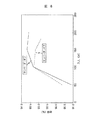
次に直流電圧切替とコンバータオン、オフの動作を図3の制御動作説明図を用いて説明する。図3は横軸に圧縮機用モータの回転数、縦軸にモータ印加電圧と通流率をとったグラフであり、負荷が一定の場合である。
【0053】
圧縮機は動作しているが冷蔵庫の庫内が冷えていない状態では、温度偏差が大きいため、速度指令が大きく実速度も大きい。両者に基づいて直流電圧を高電圧にするという指令が出力されるが、この信号は0Vであり、これが時定数回路に出力される。コンバータ制御回路側には、抵抗のR2とR3の分圧された電圧が供給され、直流電圧は例えば280Vの高電圧に設定される。この直流電圧が280V時では電動機4の回転数は高速回転で制御される。回転数の可変幅は例えば2700回転から4200回転の範囲で制御されるが、インバータ制御回路側において、前述の如く速度偏差による通流率信号をもとにドライブ信号を作成し、インバータ回路3のスイッチング素子(例えばトランジスタ)を駆動し、電動機4の速度制御を行っている。この回転数可変幅に対応する通流率は、例えば45%から95%の範囲で制御される。
【0054】
冷蔵庫の庫内が冷えてきて設定温度に近づいてくると、圧縮機用モータ4の回転数を低下させるが、電動機4の回転数指令が例えば2700回転を下回り、実回転も2700回転を下回った場合(インバータ回路3のスイッチング素子への通流率により指令値を決める場合、通流率が例えば45%以下)に、時定数回路への出力をHIGHとして、R3とR4を並列接続させ分圧値を変更し、直流電圧を例えば170Vの中電圧に設定する(B点)。この際、通流率は例えば95%となる。
【0055】
ここで、直流電圧と通流率との積が切り替え前後で一致しなければならないため、直流電圧を下げたとき通流率が100%を越えない値に設定する必要がある。回転数の可変幅は例えば1600回転から2700回転の範囲で制御され、通流率は1600回転時では例えば55%となる。
【0056】
冷蔵庫の庫内がさらに冷えてきて設定温度に近づくと、電動機4の回転数は最低回転数の例えば1600回転とするが、インバータ3のスイッチング素子への通流率が例えば55%以下、または電動機4の回転数指令が例えば最低回転数の1600回転となり、実回転も1600回転になった場合に、コンバータ制御回路側の制御をオフさせて低電圧とする(A点)。この制御は、前述したコンバータ動作判定器107により行われる。ここで直流電圧を下げたとき通流率が100%を越えない値に設定する必要がある。尚、コンバータ制御回路側の制御をオフさせるのは圧縮機用モータ4の回転数が最小値でなくともよい。
【0057】
これらの通流率や回転数の値は説明のための便宜上の値である。以上のような動作を繰り返すことにより圧縮機用モータ4の回転数の減速に伴い直流電圧を低下させ、モータの速度制御が可能である。
【0058】
次に上記とは反対に圧縮機用モータ4が増速する場合について説明する。電動機4が最低回転数で冷蔵庫の扉の開閉や温かい食品が庫内に入り庫内温度が上昇すると先程とは反対に、電動機4の回転数指令が例えば最低回転数以上となり、実回転も最低回転数以上になった場合(インバータ3のスイッチング素子への通流率をみて直流電圧指令を切り替える場合、通流率は例えば55%以上)に、コンバータ制御回路側の制御をオンさせ(A点)直流電圧を例えば170Vの中電位に設定する。
【0059】
さらに、電動機4の回転数を増加させるためには、時定数回路に与える直流電圧指令を0Vとして、R2とR3の分圧値に変更し、直流電圧を例えば280Vの高電圧に設定する。
【0060】
尚、直流電圧を切替える時は、電動機4の増速と減速時で回転数にヒステリシスを設け、切替時の回転数のハンチングを抑えることが必要である。
【0061】
また、本発明の実施の形態では直流電圧の切替をコンバータの制御オン、オフを含め、3段切替としているが、これは、直流電圧切替回路9で設定電圧を複数設けることにより更に切替回数を増やすことが可能である。
【0062】
図5はコンバータ回路2のリアクタ特性を示す。冷蔵庫の庫内が冷えてきて設定温度に近づくと、電動機4の回転数を最低回転数とし、コンバータ制御回路側(昇圧チョッパ27)の制御をオフさせるが、この際、高調波規制値を満足できなくなる問題がある。冷蔵庫においては高調波規制のガイドラインがクラスDである。電動機4の回転数制御範囲の全域に渡り、昇圧チョッパ27を通して直流電圧を制御し力率改善を行うとすれば、リアクタ25の値は1mH程度で済む。しかし、昇圧チョッパ27をオフし、高調波ガイドラインを満足させるには、リアクタ25の値は10mH以上が必要である。このため、前述の如く、リアクタ25は昇圧チョッパ27をオフする低入力(低電流)時は10mH以上の特性を持ち、昇圧チョッパ27をオンする高入力(高電流)時は1mH程度の特性を持ったリアクタ25とする。これにより、昇圧チョッパ25をオフしても、高調波ガイドラインを満足させることができる。
【0063】
図6は、直流電圧切替や最低回転数での昇圧チョッパ25をオフさせた場合のモータ効率を示す。電動機4の回転数を2700回転で切替た際、直流電圧は280Vから170Vに低下するため、モータ効率は1.2%程度向上する。これは、直流電圧が低下するため、インバータ3の通流率が増加し、モータで損失しているチョッパによる鉄損が低下するためである。また、コンバータ制御をオフさせた場合は、直流電圧が170Vから120Vに低下するため、モータ効率は2%程度向上する。この理由を図7に基づいて説明する。図7(a)は直流ステージ電圧が高い状態におけるインバータ3のスイッチング素子のPWM波形である。スイッチング素子がオンしているときはコンデンサ5から電動機電流が流れ、オフすると、還流ダイオードを介して電動機電流は還流し減衰する。このピークツーピークをΔIMとする。同様に図7(b)は、直流ステージ電圧を減少させ、(a)と同じ電圧が電動機4に印加される通流率とした場合である。この時直流ステージ電圧が低いので、スイッチング素子をオンしても電流の上昇率が小さいため、(a)とと比べΔIMは小さい。このΔIMは電動機の脈動磁束密度を表す値であり、これが小さい方が電動機の鉄損が小さいことを意味している。従って、通流率が大きいほど電動機効率が良くなる。
【0064】
図8はコンバータ制御をオフさせた場合とオンさせた場合の制御回路の効率を示す。入力(電流)が低下するとコンバータ制御をオフした方が昇圧チョッパを構成するスイッチング素子のスイッチング損失が無くなり、制御回路の効率が向上する。従って、圧縮機用モータ4と同様に、最低回転数での入力が小さいときは、コンバータ制御をオフさせた方がシステム効率が向上する。
【0065】
以上説明した実施の形態において、種々の数値を示して説明したがこれら数値は一例であり制御思想に合致する限り他の数値であっても差し支えない。
【0066】
また、本実施の形態を理解しやすくするため制御ブロック図にて説明したが、比較器100、速度指令発生器101、位置検出器102、速度演算器103、比較器104、インバータPWMデューティ指令発生器105、コンバータPAM電圧指令発生器106の電圧指令を演算する回路、コンバータ動作判定器107、転流出力器108、アンド回路109、ドライバ、過電流保護回路111、おさえめ回路131、急冷回路133、加算器135、速度指令リミッタ136、選択回路137は、ソフトウエアにて実現することができる。さらにこれにインバータを加えてLSI化することも可能である。
【0067】
以上本実施の形態により次の効果がある。圧縮機用モータの設計は、一番利用率の高い点で設計することにより(例えば最低回転数時)、モータの高効率化が図れるため、システムの省エネルギー化となる。冷蔵庫の負荷が高い時は、前述したように直流電圧制御回路により、直流電圧を増加させるため、圧縮機用モータは高速で運転することができる。更に、圧縮機用モータ4の回転数を2700回転で切替た際、直流電圧は280Vから170Vに低下するため、モータ効率は1.2%程度向上する。また、コンバータ制御をオフさせた場合は、直流電圧が170Vから120Vに低下するため、モータ効率は2%程度向上するため、更なる省エネルギー化が図れる。また、コンバータ制御をオフすることによりパワー素子のスイッチング損失が無くなり、制御回路の効率も向上する。
【0068】
直流電圧を切替える別の方法として図10の全波整流と倍電圧整流切替回路構成を示す。インバータ回路3の電源回路は整流ダイオードD1、D2、D3、D4と平滑キャパシタC1、C2とスイッチSW1から構成されている。スイッチSW1はマイコン等からなる制御回路11によって制御され、このスイッチSW1がオフの時には、全波整流回路が形成され、スイッチSW1がオンの時には、倍電圧整流回路形成される。商用電源が全波整流回路若しくは倍電圧整流回路で整流、平滑されて得られる直流電圧は、インバータ回路3のスイッチング素子に印加され、電動機4が駆動される。
【0069】
図11は全波整流から倍電圧整流に切替る際の直流電圧特性を示す。ここで示す直流電圧特性はスイッチSW1をリレーとした場合のものである。このため、全波整流回路から倍電圧整流回路となった時の直流電圧が上昇する時間は50ms程度である。この50msの間に、制御回路11は圧縮機用モータ4に印加する電圧を通流率を制御して、設定された回転数になるように制御する。スイッチSW1を半導体素子とした場合は、全波整流回路から倍電圧整流回路への切替のためのスイッチのオン、オフタイミングを制御回路11によって制御することにより、直流電圧の上昇速度を任意に可変することができる。
【0070】
尚、図11に示す直流電圧のリップルは平滑用キャパシタC1、C2の容量によって決まる。このため、リップル電圧を少なくするためには、平滑用キャパシタC1、C2の容量を大きくすればよい。
【0071】
【発明の効果】
以上本発明により、冷凍、製氷時間を大幅に短縮することができ、しかも省エネルギーモードによりモータ効率が上昇するため電力消費量を低減する冷蔵庫が提供できるという効果がある。
【図面の簡単な説明】
【図1】本実施の形態に係る冷蔵庫の制御ブロック図。
【図2】コンバータPAM電圧指令発生器の内部構成を示す図。
【図3】モータ印加電圧及び通流率を表す図。
【図4】コンバータPAM電圧指令発生器の時定数変化特性を示す図。
【図5】コンバータ回路のリアクタの特性を示す図。
【図6】直流電圧切替やコンバータ制御をオフさせた場合のモータ効率を示す図。
【図7】パルス幅変調時のパルス幅を変えたときの電流を示す図。
【図8】コンバータ制御をオフさせた場合とオンさせた場合の制御回路の効率を示す図。
【図9】電動機起動時の直流電圧の推移を示す図。
【図10】全波整流と倍電圧整流切替回路構成を示す図。
【図11】全波整流から倍電圧整流に切替る際の直流電圧特性を示す図。
【符号の説明】
1・・・商用電源、2・・・コンバータ、3・・・インバータ、4・・・電動機、131・・・おさえめ回路、133・・・急冷回路、106・・・コンバータPAM電圧指令発生器、107・・・コンバータ動作判定器。[0001]
BACKGROUND OF THE INVENTION
The present invention relates to an inverter refrigerator including a power supply circuit that rectifies AC and outputs a desired DC voltage, and an electric motor drive circuit that drives an electric motor.
[0002]
[Prior art]
2. Description of the Related Art Conventionally, a rectifier circuit that rectifies alternating current and converts it to direct current, and combines a power supply circuit that controls harmonics of a power supply current and controls direct current voltage with a drive circuit for a compressor motor, and a compressor motor. As a control device for performing the speed control, there is one described in PCTJP 97/13318 (Reference 1).
[0003]
This
[0004]
The inverter control circuit drives the electric motor by driving the switching element of the inverter circuit based on the position signal from the speed detection circuit and the conduction rate signal from the speed control circuit. This speed detection circuit detects the induced voltage of the electric motor, calculates the position of the rotor from the induced voltage, outputs a pulsed position detection signal, calculates the speed from the calculated position signal, and sends it to the speed control circuit as a speed detection value. Output. The speed control circuit calculates a duty ratio signal of the PWM pulse of the inverter so that the speed deviation becomes zero based on the speed command from the outside and the speed detection value. The speed control of the motor is performed by the inverter circuit, the electric motor, the speed detection circuit, the inverter control circuit, and the speed control circuit.
[0005]
The converter control circuit drives the switching element of the chopper circuit in accordance with a signal from the DC voltage control circuit. The DC voltage control circuit detects the DC voltage and the output signal of the speed control circuit, such as a duty ratio signal, and when the duty ratio signal reaches a predetermined value, for example, the upper limit of a certain duty ratio range, The DC voltage is controlled so as to decrease the DC voltage by a predetermined width when the duty ratio signal reaches the lower limit. The converter circuit, the converter control circuit, and the DC voltage control circuit constitute a converter DC voltage control circuit to control the DC voltage.
[0006]
Although the electric motor control device described in the above-mentioned
[0007]
[Problems to be solved by the invention]
[0008]
In addition, the power supply voltage for driving the electric motor (AC voltage supplied to the household outlet) is ± 7 of the reference value in consideration of the allowable fluctuation amount defined by the Electricity Business Act and the voltage drop in the home. .5%. In a conventional motor control device using a voltage doubler circuit, the DC stage voltage is 260V to 303V, the difference between the maximum value and the minimum value is 43V, and the motor does not start when the DC stage voltage is low. There is.
[0009]
The objective of this invention is providing the refrigerator which can achieve energy saving, having the function requested | required as a refrigerator.
[0010]
A second object of the present invention is to provide a refrigerator that achieves energy saving while reducing harmonics.
[0011]
A third object of the present invention is to provide a refrigerator capable of starting the compressor even when the voltage of the power supply fluctuates.
[0012]
[Means for Solving the Problems]
The object is to drive a compressor, an inverter for controlling the rotation of the motor,A rectifier circuit that converts alternating current to direct current and a booster circuit that boosts a direct current voltage;InverterDirectlyWith a converter supplying the flowA booster circuit control means for controlling the booster circuit so that an output voltage of the converter can output a plurality of DC voltages; an inverter control means for controlling the inverter with pulse width modulation with each of the plurality of voltages; A temperature setting device for setting the temperature,
The plurality of DC voltages are at least three levels of high, middle, and low levels,
Among the plurality of DC voltages, a high voltage and a middle voltage are voltages boosted by turning on the boosting function of the converter, and the lowest low voltage among the plurality of DC voltages is a boost voltage of the converter. With the voltage turned off,
Having an operation mode for generating a temperature command higher than the temperature set by the temperature setter;Is achieved.
[0013]
Also,UpNoteThe targetAn electric motor that drives the compressor; an inverter that controls rotation of the electric motor; a rectifier that converts alternating current into direct current; and a booster circuit that boosts direct current voltage; and a converter that supplies direct current to the inverter; Boost circuit control means for controlling the boost circuit so that the output voltage can output a plurality of DC voltages; and inverter control means for pulse width modulation control of the inverter with each of the plurality of voltages,
The plurality of DC voltages are at least three levels of high, middle, and low levels,
Among the plurality of DC voltages, a high voltage and a middle voltage are voltages boosted by turning on the boost function of the converter,
The lowest lowest voltage among the plurality of DC voltages is a voltage obtained by turning off the boosting function of the converter,
The DC voltage supplied to the inverter when starting the electric motor is higher than the value obtained by converting the AC to DCIs achieved.
[0014]
In any one of the refrigerators described above, a lower voltage among the plurality of voltages is an output voltage of a rectifier circuit of the converter.
In any one of the refrigerators described above, a reactor is provided between the rectifier circuit and the boost chopper constituting the boost circuit, and the reactor exhibits a large inductance in a small current region and a small inductance in a large current region. It is characterized by making it a reactor which exhibits. The reactor is characterized in that a coil is wound around an annular core having a gap in part.
Furthermore, in any one of the above refrigerators, the selection of the plurality of DC voltages is performed based on a rotation speed command and an actual rotation speed of the electric motor.
[0015]
DETAILED DESCRIPTION OF THE INVENTION
Demand for refrigerators includes quick freezing, such as quick freezing when cooking foods are stored frozen, quick ice making to make ice in a short time, and since refrigerators are always used with ordinary power plugs in ordinary households, there is an annual electricity bill It is energy saving that it is cheap (low annual power consumption). For quick refrigeration and quick ice making, it is achieved by increasing the number of revolutions of the compressor and increasing the amount of refrigerant circulating in the refrigeration cycle. However, in order to save energy, it is necessary to operate the compressor at a low speed. . There are the following problems when trying to achieve both the operation of the compressor at high speed and the operation of the compressor at low speed.
[0016]
Currently, motors that operate refrigerator compressors (mainly reciprocating types) are often used as brushless motors in which permanent magnets are embedded in the rotor and the rotor is rotated by generating a rotating magnetic field in the stator. Yes. The rotation speed of this brushless motor is expressed by the following equation.
[0017]
N = (V-IR) / kΦ
Here, N is the rotational speed of the motor, V is the voltage applied to the motor, I is the motor current, R is the internal resistance of the motor, k is a coefficient, and Φ is the magnetic flux density.
[0018]
As understood from this equation, the higher the motor applied voltage V and the smaller the motor internal resistance R, the higher the rotation speed. When the voltage doubler circuit is used, the DC voltage input to the inverter is 288V (about 250V when the load is connected), which is twice 144V. However, the internal resistance R of the motor can be either high-speed or low-speed. For example, in the case of high-speed rotation specifications, the value of the internal resistance R is reduced by setting the number of turns, which is the number of windings of the stator of the motor, to 120 turns (one example). However, when the specification of the electric motor is set to the high speed side as described above, there is a problem that the efficiency of the electric motor is remarkably lowered in a low speed region.
[0019]
On the other hand, if the number of windings of the stator winding is 140 turns (one example) in order to match the motor specifications to the low speed range (increase the efficiency in the low speed range), the motor applied voltage V is constant and the motor internal resistance R is Since it becomes large, there exists a problem that the rotation speed required for quick freezing and quick ice making cannot be obtained.
[0020]
Therefore, in the present embodiment, the high-speed rotation of the motor is realized by increasing the inverter input voltage in the high-speed range by matching the specifications of the motor with the low-speed range. In order to increase the inverter input voltage, that is, the DC stage voltage, a boost chopper (or a PWM controllable converter) is provided after the converter that converts AC to DC, and the boost chopper is chopped (PAM control). However, as described in
[0021]
In addition, when the boosting chopper circuit in the converter circuit performs the switching operation of the power element and boosts the DC voltage even at the minimum rotation speed, the minimum DC voltage must be controlled at 163 V or more including the voltage fluctuation. For this reason, the design of the electric motor for the compressor has a problem that the efficiency is lowered because it is not an optimum design because it is designed at a high DC voltage.
[0022]
This is because, in the case of full-wave rectification without using a voltage doubler circuit, the magnitude of the DC voltage is about 144V, but the minimum DC voltage obtained by boosting this with the lowest conduction ratio is about 163V. If the rotational speed is reduced, the pulse width of the PWM waveform becomes narrower and the magnitude of the current that flows during the ON period of the inverter increases (the maximum value of the current that flows while the switching element of a certain phase is ON). ), The difference from the lowest current in the reflux mode (period in which current flows through the reflux diode of the phase) becomes large. This difference current is proportional to the pulsating magnetic flux density, and the iron loss increases as this difference increases.
[0023]
In order to solve this problem, in the present embodiment, the DC voltage is further lowered by turning off the boost chopper in the low speed region. The PWM pulse width of the inverter can be increased by reducing the voltage of the DC stage. By widening the pulse width in this way, the difference between the maximum current value and the minimum current value in one cycle of the inverter switching element can be reduced, so that the pulsating magnetic flux density can be reduced. As a result, the electric motor Iron loss can be reduced.
[0024]
Now, in order to reduce the iron loss of the motor as described above, the boost chopper is turned off in the low-speed rotation region of the motor to realize a further lower voltage, but the higher order included in the input current by turning off the boost chopper. There was a problem that the higher harmonics increased. In the region where the step-up chopper is operating, since the current command is created based on the input AC voltage, the power factor is controlled to approximately 1, so that the current waveform becomes sinusoidal and the harmonic components are reduced. However, in the region where the step-up chopper does not operate, the current waveform is determined by the magnitude of the inductance L of the reactor of the LC filter provided in the DC stage between the converter and the inverter, and the peak value increases as the value of L decreases. A sharp current with a large and small width flows, and the current waveform becomes a sine wave as the value of L increases. Therefore, if the inductance of the reactor is increased, the problem of harmonics can be solved. However, the shape of the reactor that can reduce the harmonics is increased, for example, an electrical product provided between the refrigerator back plate and the refrigerator inner plate. There is a problem that it cannot be stored in a box.
[0025]
In order to solve this problem, the present embodiment uses a variable inductance reactor in which the inductance increases in a low current region. The reactor has a shape in which a coil is wound around iron or an amorphous material to form a circular magnetic circuit, and an air gap is provided in a part of the magnetic circuit. Simply setting the reactor on the DC side of the inverter to be iron core is described in Japanese Patent Publication No. 64-2029, which has the effect of reducing harmonics. As the value increases, it becomes smaller. In this case, there is a problem that a necessary inductance value cannot be obtained in the entire region where the step-up chopper is turned off, and harmonics increase on the low speed side in the region.
[0026]
In the present embodiment, since the reactor is a reactor having an annular iron core or the like and having a gap in part, a substantially constant inductance value L is maintained even if the current value rises from the start. The influence of harmonics can be minimized over the entire area. Further, as described below, in this embodiment, when the boost chopper is turned off, the operation is performed at one speed (minimum speed). However, even if the minimum speed differs depending on the refrigerator model, Since there is a substantially constant portion in the inductance value of the reactor, the degree of freedom of design can be expanded without changing the reactor for each model within that range.
[0027]
Hereinafter, an embodiment of the present invention will be described with reference to the drawings. FIG. 1 illustrates a control device for a refrigerator, and is an overall configuration diagram of an electric motor control device including a converter circuit using a rectifier circuit and a boost chopper circuit, and an electric motor drive circuit including an inverter circuit and an electric motor for a compressor. is there.
[0028]
The
[0029]
The
[0030]
The
[0031]
The
[0032]
The freezer compartment set temperature, which is a signal from the
[0033]
Next, control of the DC stage voltage of
[0034]
The actual rotational speed of the
[0035]
The current peak value command from the converter PAM
[0036]
Each element surrounded by a dotted line A is packaged in one integrated circuit. While the chopper off signal is being output, the output of the converter PAM
[0037]
The above-described converter control circuit has recently been made into a control IC, and a number of products that control a DC voltage by controlling an analog voltage have been commercialized.
[0038]
In the embodiment described above, the voltage command of the DC stage is determined by the speed command value and the actual speed value, but may be determined according to the conduction rate of the pulse width modulation signal of the inverter.
[0039]
Next, details of converter PAM
[0040]
However, a large change in the DC voltage occurs at the switching point, and this step-like voltage change adversely affects the PWM duty of the inverter. Therefore, in this embodiment, even if the voltage command by the program processing changes, The change gradually progressed by the circuit. This will be described below.
[0041]
The DC voltage command output by the program process changes stepwise. A signal that changes in a stepwise manner is given a time constant by the resistor R1 and the capacitor C, and the voltage is gradually increased. This voltage and the triangular wave formed by the oscillation circuit are compared by a comparator. The peak value of the output waveform of the transmission circuit is set to be equal to or less than the voltage of the DC voltage command value. Since the output of the comparator is output when the output of the time constant circuit is large, the output voltage of the time constant circuit gradually increases, and a pulse train that gradually widens is output. When the charging of the capacitor C is completed, the comparator outputs ON. Since the transistor T is turned on when the output of the comparator is on, at this time, a voltage (referred to as voltage division 1) is output to the converter control circuit side by the parallel resistance value of the resistors R3 and R4 and the voltage divided by R2. (When the transistor T is off, the voltage is divided by the resistors R2 and R3 (referred to as voltage division 2)).
[0042]
In the present embodiment, a triangular wave is formed and a time constant circuit is formed by the resistor R1 and the capacitor C. However, a rectangular wave with a different duty width corresponding to the time constant is applied to the program (software) according to the time constant. It may be output.
[0043]
Next, control at the time of starting the compressor (electric motor) will be described. The voltage range of electricity transmitted to ordinary households is allowed to vary based on the Electricity Business Law, and 281 ± 7.5% (260V to 303V) in double voltage display, considering the voltage drop due to indoor wiring. ) Fluctuation range. For this reason, when the voltage is low, the starting torque of the compressor is large, and the rotational torque of the electric motor is insufficient, which may make starting difficult. In this embodiment, when the start-up command is issued when the compressor is stopped, the DC voltage command is first controlled to a high voltage or a medium voltage to obtain a DC voltage with less fluctuation, The activation of the electric motor is started. By doing so, 281 ± 3% is obtained, so that a stable DC voltage is supplied and startup is ensured.
[0044]
That is, in converter PAM
[0045]
Here, the quick freezing operation, the quick ice making operation, and the restraining operation will be described. Home freezing performance in home refrigerators is achieved by shortening the passage time of the maximum ice crystal formation zone (-1 ° C to -5 ° C) where most of the water in the food freezes as much as possible, so that the ice crystals in the cell tissue during freezing , And the outflow of drip (fluid containing umami and nutrients) at the time of thawing due to cell destruction can be suppressed, and high quality freezing can be achieved. In order to realize this, a quick freezing button (rapid ice making button) 134 is provided on the door of the refrigerator, and quick freezing (ice making) is started when the quick freezing button 134 is pressed.
[0046]
When the quick freezing button 134 is pressed, a timer in the
[0047]
With the above quick freezing (ice making) operation function, the maximum ice crystal formation zone passage time can be made within 30 minutes, and high quality freezing has become possible.
[0048]
In recent years, the demand for energy saving in refrigerators has been screamed in response to social demands as a measure to prevent global warming. In order to answer this request, the refrigerator according to the present embodiment is provided with a
[0049]
When the
[0050]
By the way, the
[0051]
It should be noted that the quick freezing operation and the restraining operation cannot be made compatible, so that when one of them is working, it is configured to be invalidated even if the other button is pressed.
[0052]
Next, DC voltage switching and converter on / off operations will be described using the control operation explanatory diagram of FIG. FIG. 3 is a graph in which the horizontal axis represents the number of rotations of the compressor motor, and the vertical axis represents the motor applied voltage and the conduction ratio, in which the load is constant.
[0053]
In the state where the compressor is operating but the refrigerator is not cooled, the temperature deviation is large, so the speed command is large and the actual speed is large. A command to increase the DC voltage to a high voltage is output based on both, but this signal is 0 V, and this is output to the time constant circuit. A voltage obtained by dividing the resistors R2 and R3 is supplied to the converter control circuit side, and the DC voltage is set to a high voltage of, for example, 280V. When the DC voltage is 280 V, the rotation speed of the
[0054]
When the inside of the refrigerator cools and approaches the set temperature, the rotation speed of the
[0055]
Here, since the product of the DC voltage and the conduction rate must match before and after switching, it is necessary to set the conduction rate to a value that does not exceed 100% when the DC voltage is lowered. The variable range of the rotational speed is controlled in the range of 1600 to 2700 rotations, for example, and the flow rate is 55% at 1600 rotations, for example.
[0056]
When the inside of the refrigerator is further cooled and approaches the set temperature, the rotation speed of the
[0057]
These values of the flow rate and the rotational speed are values for convenience of explanation. By repeating the operation as described above, the DC voltage is reduced with the reduction in the rotational speed of the
[0058]
Next, the case where the speed of the
[0059]
Further, in order to increase the rotation speed of the
[0060]
When the DC voltage is switched, it is necessary to provide hysteresis in the rotational speed at the time of acceleration and deceleration of the
[0061]
In the embodiment of the present invention, the switching of the DC voltage is performed in three stages including on / off of the control of the converter, but this is achieved by providing a plurality of set voltages in the DC voltage switching circuit 9 to further increase the number of switching times. It is possible to increase.
[0062]
FIG. 5 shows the reactor characteristics of the
[0063]
FIG. 6 shows the motor efficiency when the DC voltage switching and the
[0064]
FIG. 8 shows the efficiency of the control circuit when the converter control is turned off and when it is turned on. When the input (current) decreases, the switching loss of the switching elements constituting the boost chopper is eliminated when the converter control is turned off, and the efficiency of the control circuit is improved. Therefore, like the
[0065]
In the embodiment described above, various numerical values are shown and described. However, these numerical values are merely examples, and other numerical values may be used as long as they match the control concept.
[0066]
Further, the control block diagram has been described to facilitate understanding of the present embodiment, but the
[0067]
As described above, the present embodiment has the following effects. The compressor motor is designed with the highest utilization factor (for example, at the minimum rotation speed), so that the motor efficiency can be improved, and the system energy can be saved. When the load on the refrigerator is high, the DC voltage is increased by the DC voltage control circuit as described above, so that the compressor motor can be operated at a high speed. Furthermore, when the rotation speed of the
[0068]
As another method for switching the DC voltage, the full-wave rectification and voltage doubler rectification switching circuit configuration of FIG. 10 is shown. The power supply circuit of the
[0069]
FIG. 11 shows the DC voltage characteristics when switching from full wave rectification to voltage doubler rectification. The DC voltage characteristics shown here are those when the switch SW1 is a relay. For this reason, the time for the DC voltage to rise when the full-wave rectifier circuit is changed to the voltage doubler rectifier circuit is about 50 ms. During this 50 ms, the
[0070]
Note that the ripple of the DC voltage shown in FIG. 11 is determined by the capacitances of the smoothing capacitors C1 and C2. For this reason, in order to reduce the ripple voltage, the capacitances of the smoothing capacitors C1 and C2 may be increased.
[0071]
【The invention's effect】
As described above, according to the present invention, the refrigeration and ice making time can be significantly shortened, and the motor efficiency is increased by the energy saving mode, so that a refrigerator that reduces power consumption can be provided.
[Brief description of the drawings]
FIG. 1 is a control block diagram of a refrigerator according to the present embodiment.
FIG. 2 is a diagram showing an internal configuration of a converter PAM voltage command generator.
FIG. 3 is a diagram showing a motor applied voltage and a conduction rate.
FIG. 4 is a view showing a time constant change characteristic of a converter PAM voltage command generator.
FIG. 5 is a diagram illustrating the characteristics of a reactor of a converter circuit.
FIG. 6 is a diagram showing motor efficiency when DC voltage switching and converter control are turned off.
FIG. 7 is a diagram showing a current when a pulse width is changed during pulse width modulation.
FIG. 8 is a diagram showing the efficiency of the control circuit when the converter control is turned off and when it is turned on.
FIG. 9 is a diagram showing a change in DC voltage when the motor is started.
FIG. 10 is a diagram showing a full-wave rectification and voltage doubler rectification switching circuit configuration.
FIG. 11 is a diagram showing DC voltage characteristics when switching from full wave rectification to voltage doubler rectification.
[Explanation of symbols]
DESCRIPTION OF
Claims (6)
前記複数の直流電圧は高中低位の少なくとも3段階の電圧であり、
前記複数の直流電圧のうち高位の電圧及び中位の電圧は前記コンバータの昇圧機能をオンさせて昇圧された電圧とし、かつ、前記複数の直流電圧のうち最も低い低位の電圧は前記コンバータの昇圧機能をオフさせた電圧とし、
前記温度設定器で設定される温度よりも高い温度指令を発生する運転モードを有することを特徴とする冷蔵庫。An electric motor that drives the compressor; an inverter that controls rotation of the electric motor; a rectifier that converts alternating current into direct current; and a booster circuit that boosts direct current voltage; and a converter that supplies direct current to the inverter ; Boosting circuit control means for controlling the boosting circuit so that the output voltage can output a plurality of DC voltages, inverter control means for pulse width modulation controlling the inverter with each of the plurality of voltages, and setting the temperature in the cabinet And a temperature setter for
The plurality of DC voltages are at least three levels of high, middle, and low levels,
Among the plurality of DC voltages, a high voltage and a middle voltage are voltages boosted by turning on the boosting function of the converter, and the lowest low voltage among the plurality of DC voltages is a boost voltage of the converter. With the voltage turned off,
A refrigerator having an operation mode for generating a temperature command higher than a temperature set by the temperature setter .
前記複数の直流電圧は高中低位の少なくとも3段階の電圧であり、
前記複数の直流電圧のうち高位の電圧及び中位の電圧は前記コンバータの昇圧機能をオンさせて昇圧された電圧とし、
前記複数の直流電圧のうち最も低い低位の電圧は前記コンバータの昇圧機能をオフさせた電圧とし、
前記電動機を起動する際における前記インバータに供給する直流電圧を、前記交流を直流に変換した値よりも高くした冷蔵庫。A motor that drives the compressor, an inverter controlling the rotation electric motor, a converter for supplying direct current to the inverter and a booster circuit for boosting the rectifier circuit and the DC voltage converting alternating current into direct current, the converter comprising of a step-up circuit control means output voltage to control the output to give so that the booster circuit a plurality of DC voltage, and an inverter control unit for pulse width modulation controlling said inverter in each of the plurality of voltages,
The plurality of DC voltages are at least three levels of high, middle, and low levels,
Among the plurality of DC voltages, a high voltage and a middle voltage are voltages boosted by turning on the boost function of the converter,
The lowest low voltage among the plurality of DC voltage and the voltage was turned off the boost function of the converter,
A refrigerator in which a DC voltage supplied to the inverter when starting the electric motor is higher than a value obtained by converting the alternating current into direct current .
このリアクタを、小電流域で大きなインダクタンスを呈し、大電流域で小さなインダクタンスを呈するようなリアクタとした請求項1乃至3のいずれかに記載の冷蔵庫。Said rectifying circuit, a reactor between a step-up chopper constituting the booster circuit provided,
The reactor exhibits a large inductance with a small current region, the refrigerator according to any one of claims 1 to 3 was reactor, such as exhibiting a small inductance with a large current region.
Priority Applications (7)
| Application Number | Priority Date | Filing Date | Title |
|---|---|---|---|
| JP29331898A JP3837943B2 (en) | 1998-09-03 | 1998-10-15 | refrigerator |
| TW088109928A TW528847B (en) | 1998-06-18 | 1999-06-14 | Refrigerator |
| KR1019990022652A KR100337765B1 (en) | 1998-06-18 | 1999-06-17 | Refrigerator |
| US09/335,781 US6244061B1 (en) | 1998-06-18 | 1999-06-18 | Refrigerator |
| CNB991109937A CN1185455C (en) | 1998-06-18 | 1999-06-18 | Refrigerator |
| US09/833,556 US6367273B2 (en) | 1998-06-18 | 2001-04-13 | Refrigerator |
| KR10-2001-0056887A KR100471939B1 (en) | 1998-06-18 | 2001-09-14 | Refrigerator |
Applications Claiming Priority (3)
| Application Number | Priority Date | Filing Date | Title |
|---|---|---|---|
| JP10-249295 | 1998-09-03 | ||
| JP24929598 | 1998-09-03 | ||
| JP29331898A JP3837943B2 (en) | 1998-09-03 | 1998-10-15 | refrigerator |
Publications (2)
| Publication Number | Publication Date |
|---|---|
| JP2000146392A JP2000146392A (en) | 2000-05-26 |
| JP3837943B2 true JP3837943B2 (en) | 2006-10-25 |
Family
ID=26539210
Family Applications (1)
| Application Number | Title | Priority Date | Filing Date |
|---|---|---|---|
| JP29331898A Expired - Fee Related JP3837943B2 (en) | 1998-06-18 | 1998-10-15 | refrigerator |
Country Status (1)
| Country | Link |
|---|---|
| JP (1) | JP3837943B2 (en) |
Families Citing this family (9)
| Publication number | Priority date | Publication date | Assignee | Title |
|---|---|---|---|---|
| JP2005083683A (en) * | 2003-09-10 | 2005-03-31 | Hitachi Home & Life Solutions Inc | Refrigerator and operation control method thereof |
| KR100623997B1 (en) | 2004-10-07 | 2006-09-15 | 삼성전자주식회사 | Electric motor drive |
| US9692289B2 (en) | 2013-06-25 | 2017-06-27 | Mitsubishi Electric Corporation | DC power-supply device and refrigeration-cycle application device including the same |
| CN105493390B (en) | 2013-09-06 | 2018-09-11 | 三菱电机株式会社 | Continuous-current plant and refrigeration cycle application apparatus with the continuous-current plant |
| MX353700B (en) | 2013-10-18 | 2018-01-25 | Mitsubishi Electric Corp | Dc power source device, motor drive device, air conditioner, and refrigerator. |
| KR101811153B1 (en) | 2013-10-29 | 2018-01-25 | 미쓰비시덴키 가부시키가이샤 | Dc power supply device and refrigeration cycle device |
| JP6197690B2 (en) * | 2014-02-21 | 2017-09-20 | トヨタ自動車株式会社 | Motor control system |
| WO2017110081A1 (en) * | 2015-12-22 | 2017-06-29 | パナソニックIpマネジメント株式会社 | Brushless dc motor voltage control device and air-blowing device equipped with same |
| JP2020125882A (en) * | 2019-02-06 | 2020-08-20 | パナソニックIpマネジメント株式会社 | refrigerator |
-
1998
- 1998-10-15 JP JP29331898A patent/JP3837943B2/en not_active Expired - Fee Related
Also Published As
| Publication number | Publication date |
|---|---|
| JP2000146392A (en) | 2000-05-26 |
Similar Documents
| Publication | Publication Date | Title |
|---|---|---|
| KR100471939B1 (en) | Refrigerator | |
| US5793623A (en) | Air conditioning device | |
| TWI330927B (en) | Ride-through method and system for hvac&r chillers | |
| JP2567777B2 (en) | Compressor start-up control method for air conditioners that are used for both heating and cooling | |
| JP2007532861A (en) | System and method for capacity control of multiple compressor cooling systems | |
| JP3837943B2 (en) | refrigerator | |
| KR100376902B1 (en) | Refrigerator | |
| WO2017208873A1 (en) | Motor drive apparatus, and electric device having compressor using same | |
| JP2001263256A (en) | Control device for compressor | |
| JP4095865B2 (en) | Electric motor drive device and electric motor application device | |
| JPH1169861A (en) | Motor control device, freezing cycle device and air conditioner using the motor control device | |
| JP6970871B2 (en) | Motor drive device and refrigerator using it | |
| JP6979568B2 (en) | Motor drive device and refrigerator using it | |
| JP2005083683A (en) | Refrigerator and operation control method thereof | |
| KR100296691B1 (en) | Freezer | |
| JP2000283623A (en) | Refrigerator for refrigerated vehicle | |
| JPH10210784A (en) | Compressor motor controller | |
| JPH04190050A (en) | Condenser cooling fan control device | |
| JP2002325466A (en) | Voltage control device, voltage control system, and refrigerated car | |
| JPS6054571B2 (en) | heat source device | |
| Dieckmann et al. | Variable frequency drives, part 1: the technology | |
| JP2003018877A (en) | Refrigerator | |
| JP2007330012A (en) | Refrigerator | |
| JP2003153574A (en) | Motor controller | |
| JP2006304386A (en) | Motor driving unit and refrigerator |
Legal Events
| Date | Code | Title | Description |
|---|---|---|---|
| A977 | Report on retrieval |
Free format text: JAPANESE INTERMEDIATE CODE: A971007 Effective date: 20051215 |
|
| A131 | Notification of reasons for refusal |
Free format text: JAPANESE INTERMEDIATE CODE: A131 Effective date: 20060104 |
|
| A521 | Written amendment |
Free format text: JAPANESE INTERMEDIATE CODE: A523 Effective date: 20060306 |
|
| RD01 | Notification of change of attorney |
Free format text: JAPANESE INTERMEDIATE CODE: A7421 Effective date: 20060417 |
|
| TRDD | Decision of grant or rejection written | ||
| A01 | Written decision to grant a patent or to grant a registration (utility model) |
Free format text: JAPANESE INTERMEDIATE CODE: A01 Effective date: 20060711 |
|
| A61 | First payment of annual fees (during grant procedure) |
Free format text: JAPANESE INTERMEDIATE CODE: A61 Effective date: 20060724 |
|
| FPAY | Renewal fee payment (event date is renewal date of database) |
Free format text: PAYMENT UNTIL: 20100811 Year of fee payment: 4 |
|
| FPAY | Renewal fee payment (event date is renewal date of database) |
Free format text: PAYMENT UNTIL: 20100811 Year of fee payment: 4 |
|
| FPAY | Renewal fee payment (event date is renewal date of database) |
Free format text: PAYMENT UNTIL: 20110811 Year of fee payment: 5 |
|
| FPAY | Renewal fee payment (event date is renewal date of database) |
Free format text: PAYMENT UNTIL: 20120811 Year of fee payment: 6 |
|
| FPAY | Renewal fee payment (event date is renewal date of database) |
Free format text: PAYMENT UNTIL: 20130811 Year of fee payment: 7 |
|
| LAPS | Cancellation because of no payment of annual fees |