JP3835423B2 - Intake device for internal combustion engine - Google Patents
Intake device for internal combustion engine Download PDFInfo
- Publication number
- JP3835423B2 JP3835423B2 JP2003100196A JP2003100196A JP3835423B2 JP 3835423 B2 JP3835423 B2 JP 3835423B2 JP 2003100196 A JP2003100196 A JP 2003100196A JP 2003100196 A JP2003100196 A JP 2003100196A JP 3835423 B2 JP3835423 B2 JP 3835423B2
- Authority
- JP
- Japan
- Prior art keywords
- intake
- partition wall
- control valve
- valve
- flow path
- Prior art date
- Legal status (The legal status is an assumption and is not a legal conclusion. Google has not performed a legal analysis and makes no representation as to the accuracy of the status listed.)
- Expired - Lifetime
Links
- 238000002485 combustion reaction Methods 0.000 title claims description 29
- 238000005192 partition Methods 0.000 claims description 72
- 238000011144 upstream manufacturing Methods 0.000 claims description 39
- 238000005266 casting Methods 0.000 claims description 5
- 239000000446 fuel Substances 0.000 description 10
- 238000010586 diagram Methods 0.000 description 6
- 229910052751 metal Inorganic materials 0.000 description 6
- 239000002184 metal Substances 0.000 description 6
- 238000004891 communication Methods 0.000 description 5
- 229910000831 Steel Inorganic materials 0.000 description 4
- 230000000052 comparative effect Effects 0.000 description 4
- 238000002347 injection Methods 0.000 description 4
- 239000007924 injection Substances 0.000 description 4
- 238000000034 method Methods 0.000 description 4
- 239000010959 steel Substances 0.000 description 4
- 238000003754 machining Methods 0.000 description 3
- 239000007921 spray Substances 0.000 description 3
- 230000007423 decrease Effects 0.000 description 2
- 230000002708 enhancing effect Effects 0.000 description 2
- 238000009423 ventilation Methods 0.000 description 2
- 229910000838 Al alloy Inorganic materials 0.000 description 1
- 230000006866 deterioration Effects 0.000 description 1
- 230000000694 effects Effects 0.000 description 1
- 230000002093 peripheral effect Effects 0.000 description 1
- 238000005086 pumping Methods 0.000 description 1
- 230000002787 reinforcement Effects 0.000 description 1
- 239000013598 vector Substances 0.000 description 1
Images


Classifications
-
- Y—GENERAL TAGGING OF NEW TECHNOLOGICAL DEVELOPMENTS; GENERAL TAGGING OF CROSS-SECTIONAL TECHNOLOGIES SPANNING OVER SEVERAL SECTIONS OF THE IPC; TECHNICAL SUBJECTS COVERED BY FORMER USPC CROSS-REFERENCE ART COLLECTIONS [XRACs] AND DIGESTS
- Y02—TECHNOLOGIES OR APPLICATIONS FOR MITIGATION OR ADAPTATION AGAINST CLIMATE CHANGE
- Y02T—CLIMATE CHANGE MITIGATION TECHNOLOGIES RELATED TO TRANSPORTATION
- Y02T10/00—Road transport of goods or passengers
- Y02T10/10—Internal combustion engine [ICE] based vehicles
- Y02T10/12—Improving ICE efficiencies
Landscapes
- Cylinder Crankcases Of Internal Combustion Engines (AREA)
Description
【0001】
【発明の属する技術分野】
この発明は、シリンダに接続された吸気ポートを含む内燃機関の吸気装置、特に、シリンダ内のタンブルやスワール等のガス流動の強化を図った吸気装置の改良に関する。
【0002】
【従来の技術】
例えば、火花点火式内燃機関における安定した燃焼の実現のためには、タンブルもしくはスワールといったシリンダ内のガス流動が非常に重要であり、より広い運転領域でガス流動を強化できることが必要である。
【0003】
従来から知られているシリンダ内のガス流動を強化する方法の一つは、特許文献1に見られるように、吸気ポートの通路断面の一部を遮蔽する吸気制御弁を用い、吸気ポート内を流れる吸気流を吸気ポートの一方の側に片寄らせる方法である。例えば、タンブル生成のためには、吸気ポートの下側に吸気制御弁が配置され、吸気ポートの上側に片寄って吸気が流れることで、シリンダ内のタンブルが強化されることになる。
【0004】
また、ガス流動を強化する他の方法として、特許文献2に見られるように、吸気ポート内に、その長手方向に沿った隔壁を設けるとともに、この隔壁により区画された一方の流路を開閉弁により開閉するようにした構成が知られている。例えば、タンブル生成のためには、吸気ポート内を上下に仕切るように隔壁が設けられ、その下側の流路が開閉弁によって閉じられることになる。これにより、上側の流路のみを通してシリンダ内に吸気が流入するため、前述した例に比べて流速や指向性が高く得られ、一般に、タンブル比はより向上する。
【0005】
【特許文献1】
特開2002−54535号公報
【0006】
【特許文献2】
特開平6−159079号公報
【0007】
【発明が解決しようとする課題】
上記のような公知の方法は、いずれも、ガス流動強化時に、吸気ポートの通路断面積を、吸気制御弁等によって実質的に減少させることになり、ベースとなる吸気ポート断面積に対する有効な通路断面積の割合を「開口率」として定義すると、一般に、開口率が小さいほどガス流動が高く得られる。しかしながら、開口率を小とすると、通気抵抗は増大し、シリンダ内に吸入可能な吸気量が減少するので、吸気制御弁等を閉じてガス流動を強化することができる運転条件は、比較的狭い範囲に制限されてしまう。
【0008】
この発明は、開口率を過度に小さくすることなくシリンダ内のガス流動を強化することができる内燃機関の吸気装置を提供することを目的とする。
【0009】
【課題を解決するための手段】
この発明は、内燃機関のシリンダヘッド内部の吸気ポートに、吸気マニホルド側のブランチ部通路が連続することによって、各シリンダに至る吸気通路が構成され、かつ上記吸気ポートの下流側の先端を吸気弁が開閉する内燃機関の吸気装置を前提としており、上記吸気ポートをその断面で2つの領域に区画するように、吸気ポートの長手方向に沿って設けられた隔壁と、この隔壁により区画された一方の流路を開閉する吸気制御弁と、を備えている。上記吸気制御弁は、上記吸気マニホルド側に回転軸を有する回動可能な板状の弁体からなり、上記隔壁の上流端に近接して上記ブランチ部通路の下流端部に位置している。さらに、本発明では、上記吸気制御弁が上記一方の流路を遮蔽した閉位置において、上記隔壁の上流端と上記弁体との間に、2つの流路の間の連通路となるように、間隙が設けられている。
上記吸気制御弁の上記回転軸は、上記隔壁の延長線上に位置している。また、上記弁体は、その閉位置において一方の流路を遮蔽するように回転軸から一方へ延びた主弁部を有するとともに、回転軸から上記主弁部とは反対側へ延びた延長部を有し、この延長部が、閉位置においては、他方の流路側に突出する。これにより、該延長部の直線状をなす先端縁と同じく直線状をなす上記隔壁上流端縁との間で上記間隙が一定幅の直線状に形成される。また、開位置においては、上記間隙を狭めるように間隙内に位置する。そして、上記吸気制御弁が一方の流路を遮蔽した閉位置にあるときに、上記弁体が、吸気流を他方の流路へ案内する方向に傾斜しているとともに、上記主弁部が回転軸よりも一方の流路の側の領域を塞いでおり、上記延長部の下流に生じる局部的な圧力低下により上記間隙を介して一方の遮蔽された流路から他方の開放された流路へ吸気が還流するように構成されている。
【0010】
本発明では、上記吸気制御弁が一方の流路を遮蔽した閉位置にあるときに、他方の流路のみを通して吸気がシリンダ側へ流れることになり、吸気弁の周囲の一方に片寄った位置から相対的に多くの吸気がシリンダ内に流れ込む。これと同時に、吸気制御弁が吸気流を絞ることによって該吸気制御弁の下流側に局部的な圧力低下が生じ、これが、連通路となる間隙の出口側(他方の流路に面する側)に作用する。従って、吸気制御弁で遮蔽された一方の流路の下流側の端部と上記間隙との間で圧力差が発生し、上記端部から吸気が吸い込まれるとともに、吸気ポートの上流側へ向かって逆に流れ、かつ上記間隙を通して他方の流路へと合流する。つまり、遮蔽した流路を介して吸気の一部が上流側へと還流する。そのため、吸気弁の周囲を通る吸気流の流量ないしは流速の不均衡が一層拡大し、シリンダ内のガス流動が効果的に強化される。
【0011】
特に、本発明では、各シリンダに至る吸気通路の中で、シリンダヘッド側に隔壁が形成されるとともに、吸気マニホルドのブランチ部側に吸気制御弁が配置されて、両者間に、連通路となる間隙が確保される。そのため、構成の複雑化を最小限としつつ、十分な精度をもって隔壁と吸気制御弁とを所定の位置関係に構成することが容易となる。
【0012】
【発明の効果】
この発明に係る内燃機関の吸気装置によれば、吸気制御弁が遮蔽した流路を介して一部の吸気が還流することによってシリンダ内のガス流動を効果的に向上させることができ、特に、吸気制御弁による開口率を小さくせずにより強いガス流動を得ることができる。従って、通気抵抗の増加に伴うポンピングロスの増加が抑制され、またシリンダ内に流入する吸気量を多く確保できることから広範な運転領域でガス流動の強化が図れる。
【0013】
また、本発明によれば、シリンダヘッド側に隔壁を、吸気マニホルド側に吸気制御弁を、それぞれ配置したことにより、構成の複雑化を最小限としつつ、隔壁と吸気制御弁とを備えた吸気装置を実現することができ、かつ両者間に必要な間隙の精度を高く得ることが可能となる。
【0014】
【発明の実施の形態】
以下、この発明の好ましい実施の形態を図面に基づいて詳細に説明する。
【0015】
図1および図2は、この発明をポート噴射型火花点火式内燃機関の吸気装置に適用した第1実施例を示しており、これは、ガス流動としてタンブルの強化を図った例である。シリンダブロック1に円筒状のシリンダ2が複数形成されているとともに、その頂部を覆うシリンダヘッド3に、ペントルーフ型の燃焼室4が凹設されている。この燃焼室4の2つの傾斜面にそれぞれ開口するように、吸気ポート5および排気ポート6が形成されており、吸気ポート5の先端を吸気弁7が開閉し、かつ排気ポート6の先端を排気弁8が開閉している。ここで、吸気ポート5は、先端部が中央壁部15を介して二股状に分岐しており、各気筒に一対設けられた吸気弁7がそれぞれの先端を開閉している。同様に、排気弁8も各気筒に一対設けられている。そして、これらの4つの弁に囲まれた燃焼室4中心部に、点火栓9が配置されている。なお、シリンダ2内に配置されたピストン10は、本発明の要部ではないので、頂面が平坦な単純形状として図示してあるが、必要に応じてタンブルを用いた燃焼に適した所望の形状に構成される場合もある。
【0016】
そして、図1に示すように、本実施例では、吸気ポート5をその断面で上下2つの領域に区画するように、吸気ポート5の長手方向に沿った隔壁11が設けられている。この隔壁11は、例えばアルミニウム合金にてシリンダヘッド3を鋳造する際に別体の金属板(例えば鋼板)を鋳込むことによって構成されており、その下流端11aができるだけ下流側つまり吸気弁7に近い位置となるように配置されている。より詳しくは、吸気ポート5が二股状に分岐する中央壁部15上流の分岐点15aの直前まで、上記下流端11aが延びている。ここで、図示例では、この隔壁11が存在する長手方向の部分で吸気ポート5がほぼ直線状をなし、これに対応して隔壁11もほぼ直線状の断面形状をなしているが、必ずしもこれに限定されるものではなく、吸気ポート5が湾曲している場合には、これに沿うように湾曲した隔壁11が設けられる。また、隔壁11の上流端11bは、吸気マニホルド21が取り付けられるシリンダヘッド3の吸気マニホルド取付座面22に近い位置まで延長されているものの、該取付座面22から内側(吸気ポート5下流側)に僅かに後退した位置にある。図2に示すように、この隔壁11の上流端11bおよび下流端11aは、上記取付座面22と平行な直線状をなし、従って、上記隔壁11を構成する金属板は、全体として台形状をなしている。なお、隔壁11を構成する金属板の側縁には、鋳込んだ状態での結合強度を高めるために、それぞれ一対の突起部11cが形成されている。
【0017】
上記のように隔壁11が設けられていることにより、吸気ポート5内は、その下流側部分を除き、上側の通路状部分つまり第1流路5Aと下側の通路状部分つまり第2流路5Bとに分割される。
【0018】
なお、当業者には明らかなように、本明細書において吸気ポート5や吸気流等についての「上」「下」とは、シリンダ2の上下を基準とするものであり、空間上の絶対的な上下の意味ではない。
【0019】
また上記吸気ポート5は、上記吸気マニホルド21の各気筒毎のブランチ部23におけるブランチ部通路24に連続しており、これによって、上流側の図示せぬコレクタ部から各シリンダ2に至る気筒毎の吸気通路が構成されている。上記ブランチ部通路24は、吸気ポート5に近い下流側部分では、吸気ポート5の形状に沿った直線状をなし、かつこれよりも上流側の部分では、上方に位置するコレクタ部へ向かって上方へ湾曲している。
【0020】
そして、上記ブランチ部通路24の下流側の端部に、上記隔壁11により区画されてなる下側の第2流路5Bを入口側つまり上流端で遮蔽するように、各気筒毎に吸気制御弁31が設けられている。この吸気制御弁31は、回転軸32を中心に回動可能な板状の弁体33を備えたもので、上記回転軸32が、上記隔壁11の上流側への延長線上、特に、吸気マニホルド21のブランチ部23側に位置し、この回転軸32に、板状をなす弁体33の一端が固定されている。詳しくは、上記弁体33は、上記の第2流路5Bを開閉するために回転軸32から一方へ延びた主弁部33aを有するとともに、これとは反対側へ相対的に短く延びた延長部33bを有している。上記主弁部33aは、ブランチ部通路24の下側の断面形状に応じて、楕円を2分したような形状(図2参照)をなしている。これに対し、上記延長部33bの先端つまり下流端33cは、図2に示すように、吸気マニホルド取付座面22および隔壁11の上流端11bと平行な直線状をなしている。また、上記回転軸32は、上記隔壁11の上流端11bに近接しているものの、少なくとも上記延長部33bが干渉しない程度に、上記上流端11bから離れている。本実施例では、上記延長部33bの先端つまり下流端33cが、ブランチ部23の先端フランジ面(吸気マニホルド取付座面22と実質的に同じ面)よりもシリンダヘッド3側に突出せず、該先端フランジ面よりも僅かに上流側に後退して位置している。
【0021】
上記回転軸32は、図示せぬアクチュエータに連係しており、タンブルを強化すべき運転条件では、弁体33が図示の姿勢のような閉位置に制御され、下側の第2流路5Bを、その入口側で遮蔽する。このとき、主弁部33aは回転軸32より上流側にあり、吸気制御弁31上流側から流れてきた吸気流を上側の第1流路5Aへ案内する方向に、弁体33が傾斜した状態となる。換言すれば、このような所定の傾斜位置で回転軸32より下側の領域を完全に塞ぐように、上記主弁部33aの外形状が設定されている。上記の閉位置における弁体33の傾斜角α(隔壁11を上流側へ延長した基準線mと弁体33とのなす角を傾斜角αと定義する)は、30°〜40°とすることが、後述するタンブル強さのばらつきの抑制の上で、望ましい。また、このような閉位置に回動すると、主弁部33aの反対側に位置する下流側の延長部33bは、隔壁11よりも上方つまり第1流路5A側に突出した状態となる。そして、隔壁11の上流端11bと弁体33の延長部下流端33cとの間には、第1流路5A上流端と第2流路5B上流端とを連通させる連通路となる適宜な大きさの間隙12が生じる。この実施例では、図2に示すように、それぞれ直線状をなす隔壁上流端11bと弁体下流端33cとの間に、一定幅の間隙12が確保される。
【0022】
一方、吸気量が大となる運転条件、例えば高速高負荷域では、上記吸気制御弁31は、吸気ポート5の長手方向に沿った開位置に制御され、第2流路5Bを開放することとなる。この開位置では、上記弁体33が隔壁11と直線状に連続した姿勢となり、吸気流と平行となる。そして、延長部33bも上記隔壁11と直線状に整列し、延長部33bの先端(下流端33c)と隔壁11の上流端11bとが互いに隣接した状態となる。
【0023】
上記吸気制御弁31は、この実施例では、各気筒毎に、円環状をなす制御弁フレーム34を具備し、この制御弁フレーム34の内周側に、各弁体33が回動可能に保持されている。つまり、予め、弁体33と制御弁フレーム34とがユニット化されており、これを、吸気マニホルド21のブランチ部23の先端開口部内周に装填することで、各弁体33が上記のようにブランチ部通路24内に配置される。そして、上記回転軸32に相当するシャフトが、複数気筒のブランチ部23を横切るような形で挿入され、各弁体33と連結されるようになっている。なお、ブランチ部23の先端開口部内周には、上記制御弁フレーム34に対応する段部が凹設されており、制御弁フレーム34をこの段部に填め込んだ状態で、吸気マニホルド21をシリンダヘッド3に取り付けることによって、制御弁フレーム34つまり吸気制御弁31が固定保持されている。
【0024】
また、各気筒の吸気ポート5へ向けて燃料を噴射する燃料噴射弁41が、シリンダヘッド3の吸気ポート5上方に配置されている。この燃料噴射弁41は、一対の吸気弁7に対応して略V字形に分岐した噴霧を形成し得る形式のもので、特に、図1に示すように、吸気弁7の弁頭部を指向した噴霧が隔壁11と干渉することのないように、比較的下流側つまり吸気弁7寄りに配置されている。なお、この燃料噴射弁41の噴霧が通過する凹部42が、吸気ポート5の上壁面に形成されている。
【0025】
なお、図示しないが、この内燃機関は、排気系から吸気系に排気の一部を還流させるために、排気還流制御弁などを含む公知の排気還流装置を備えており、特に、シリンダ2内のタンブルを積極的に利用して高い排気還流率の下での安定した燃焼を実現することにより、部分負荷域での燃費低減を図った構成となっている。還流排気は、吸気マニホルド21の図示せぬコレクタ部などにまとめて導入してもよく、あるいは、各気筒のブランチ部通路24にそれぞれ分配して導入することも可能である。
【0026】
次に、図3の説明図を用いて、上記実施例の構成における作用について説明する。吸気行程において、吸気弁7が開き、かつピストン10が下降すると、吸気は、吸気弁7周囲の弁隙間を通して、シリンダ2内に流入する。このとき、吸気制御弁31が開位置にあれば、第1流路5Aおよび第2流路5Bの双方を通して吸気が流れ、吸気弁7の周囲の各部からほぼ均等に吸気が流れ込むので、シリンダ2内に発生するガス流動は比較的弱い。
【0027】
これに対し、吸気制御弁31が図3に示すように閉位置に制御されると、下側の第2流路5Bが遮蔽され、上側の第1流路5Aのみを通して吸気がシリンダ2側へ流れることになる。特に、図3に示すように吸気ポート5の上側の内壁面5a(以下、上側内壁面5aと記す)に沿って吸気流が偏在し、吸気ポート5の下側の内壁面5b(以下、下側内壁面5bと記す)に沿う流れは非常に少ない。そのため、吸気弁7の周囲について見たときに、吸気弁7の下側つまりシリンダ2外周に近い側の弁隙間20aでは、吸気の流量が少ないとともに、流速も低く、また吸気弁7の上側つまり点火栓9に近い側の弁隙間20bでは、吸気の流量が多いとともに、流速も高くなる。この結果、シリンダ2内には、矢印で示すように、吸気弁7側から排気弁8側を経てピストン10頂面へと向かうタンブル(いわゆる順タンブル)が生じる。そして、本実施例では、吸気制御弁31が図示のように閉位置にあると、この部分が絞り部となって吸気流が第1流路5Aのみを流れるように絞られるので、第1流路5Aにおいて、隔壁11の上流端11b付近で、局部的な圧力低下が生じ、破線13で示すような低圧領域が発生する。第1流路5Aと第2流路5Bとの間の連通路となる間隙12は、この低圧領域13に向かって開口する形となるので、第2流路5Bの下流側の開口端14との間で圧力差が生じる。そのため、上記開口端14が吸気取り入れ口となり、上記圧力差によって、上記開口端14から吸気が取り込まれるとともに、吸気ポート5の上流側へ向かって逆に流れ、かつ間隙12から第1流路5Aへと合流する。つまり、第1流路5A通過後に吸気ポート5の下側の領域へと拡がろうとした吸気が第2流路5Bを通して上流側へ還流し、上側の第1流路5Aへと戻されることになる。そのため、吸気弁7の下側の弁隙間20aを通る吸気流がより少なくなると同時に、上側の弁隙間20bを通る吸気流がより多くなり、シリンダ2内のタンブルがより強く得られる。特に、下側の弁隙間20aを通る吸気流は、シリンダ2内のタンブルを弱めるように作用するのであるが、上記実施例では、上側の弁隙間20bを通る流れによりタンブルが強められるのみならず、このタンブルを弱めるように作用する下側の弁隙間20aを通る流れが抑制されることから、非常に効果的にタンブルが強化される。
【0028】
このようにシリンダ2内に形成される強いタンブルは、燃費向上のために大量に排気還流を行う上で非常に有用であり、部分負荷域において、高排気還流率となる大量の排気還流を与えつつ吸気制御弁31を閉じて強いタンブルを生成することによって、安定した燃焼を実現でき、燃費向上を達成できる。
【0029】
特に、上記の実施例では、図示の閉位置において、弁体33の延長部33bが隔壁11よりも上方つまり第1流路5A側に突出しているので、その背面側でより効果的に低圧領域が発達し、間隙12を通した吸気の還流が確実に行われる。
【0030】
そして、高速高負荷域などで吸気制御弁31が開位置となったときには、前述のように弁体33と隔壁11とが直線状に整列することで吸気抵抗の増加が回避されるとともに、延長部33bによって間隙12が狭められるため、吸気流の乱れが抑制される。なお、本実施例では、図1に示すように、弁体33が一定厚の板状ではなく、主弁部33aおよび延長部33bの双方で、先端へ向かって徐々に薄くなるテーパ状の断面形状を有しているので、吸気流が円滑に流れ、吸気抵抗がより低減する。
【0031】
図4は、上記実施例の吸気装置における実際の吸気の流れを解析したものであり、各部の流れの速さおよび方向を、微細なベクトルつまり矢印でもって示している。矢印の粗密は、流量を示し、矢印が密に集まっている部位は、流量が大であることを意味する。また、図5は、比較例として、連通路となる間隙12を閉塞したものの吸気の流れを同様に示している。つまり、図5の構成は、単に隔壁11と吸気制御弁31とで吸気流を偏在させるようにした従来技術に相当する。なお、両者とも吸気制御弁31の開口率は同一(約20%)である。
【0032】
これらの図を対比すれば明らかなように、比較例である図5のものでは、上側の第1流路5Aを通過した吸気流は、隔壁11の下流端11aよりも下流で下方へも拡散していくので、吸気弁7の下側の弁隙間20aを通る吸気流が少なからず存在する。なお、隔壁11の下側の第2流路5Bでは殆ど流れが見られず、淀んだ状態となる。これに対し、本発明を示す図4では、吸気弁7寄りの下側領域から下側の第2流路5Bを通して吸気が還流し、この結果、吸気弁7の下側の弁隙間20aを通る吸気流が極端に減少する。また、これに伴って上側の弁隙間20bを通る吸気流が増加する。従って、効果的にタンブルを強化できる。
【0033】
図6は、図4もしくは図5のように隔壁11と吸気制御弁31とを用いた吸気装置におけるタンブルの強さと吸入空気量との関係を示している。なお、ここでは、タンブルの強さを、吸気行程中のタンブル比の最大値でもって表している。一般に、タンブルが弱いと燃焼が遅く不安定となる傾向があり、タンブルが強いと燃焼が速く安定となる。図の実線で示す特性は、図5の比較例の場合の関係を示しており、開口率を小さく設定するほどタンブルが強くなるものの吸入空気量が少なくなり、逆に、開口率を大きく設定するほど吸入空気量が多く得られるもののタンブルが弱くなる、という相関関係がある。吸入空気量が少なくなることは、タンブルの生成が可能な運転領域(つまり吸気制御弁31を閉じることができる運転領域)が狭いことを意味し、吸入空気量が多いことは、逆にその運転領域が広いことを意味する。本発明(例えば図4の構成)によれば、破線で示すような領域に、タンブル強さと吸入空気量との相関を得ることができる。つまり、同一のタンブル強さであれば、吸入空気量をより大きく確保でき、また同一の吸入空気量(開口率)であれば、タンブルをより強く得ることができる。
【0034】
従って、燃費向上手段として前述したように大量排気還流と強いタンブルとを組み合わせた運転を、より広い運転領域において行うことができ、内燃機関全体として、大幅な燃費向上が図れる。そして、同じ運転領域で比較すると、タンブルがより強く生成されることから、より大量の排気還流が可能となり、一層の燃費向上が可能である。
【0035】
このように、適宜な間隙12を生じるように配置した隔壁11と吸気制御弁31とによって効果的なタンブル強化を図ることができるが、本実施例では、隔壁11がシリンダヘッド3側に金属板を鋳込むことによって構成され、かつ吸気制御弁31がシリンダヘッド3とは別に吸気マニホルド21のブランチ部23先端部に配置されていることから、構造の複雑化や組立性の悪化を最小限のものとすることができる。特に、吸気制御弁31を制御弁フレーム34とともにユニット化した状態でブランチ部23先端に装填できるので、組立時の作業性が良好なものとなる。また、吸気マニホルド21のシリンダヘッド3への取付前に、隔壁上流端11bの位置や吸気制御弁31の延長部下流端33cの位置を確認ないしは調整することで、両者間に生じる間隙12の精度を容易に確保でき、間隙12のばらつきに伴うタンブル強さのばらつきを回避できる。
【0036】
さらに、本実施例では、シリンダヘッド3に鋳込んだ隔壁11の上流端11bが吸気マニホルド取付座面22よりも後退しているので、シリンダヘッド3の鋳造後に吸気マニホルド取付座面22を機械加工する際に、工具が鋼板などからなる隔壁11に接触することがなく、その加工が容易である。また同時に、吸気制御弁31の弁体33がブランチ部23の先端フランジ面よりも後退しているため、例えば組立作業中に弁体33が吸気マニホルド取付座面22に当たって損傷する、等の不具合が生じにくい。
【0037】
また、図1に示したように、吸気制御弁31が閉位置にあるときの弁体33の傾斜角αが比較的小さいことから、間隙12の寸法誤差に対するタンブル強さのばらつきが小さくなる。すなわち、図7に示すように、ある範囲内においては、吸気制御弁31の閉位置における間隙12が大きいほどタンブル強さが大となる傾向にあるが、弁体33の傾斜角αが90°に近い場合に破線で示すような特性となるのに対し、弁体33の傾斜角αが相対的に小さい場合には、実線で示すように間隙12の大きさの変化に対するタンブル強さの変化が相対的に緩やかな特性となる。従って、ある要求タンブル強さを得ようとした場合に、間隙12のある一定の誤差Aに対するタンブル強さのばらつきは、それぞれ符号B,Cで示すように、後者の方が明らかに小さくなる。従って、例えば、多気筒機関における各気筒の燃焼のばらつきを、より小さく抑制することができる。
【0038】
次に、図8および図9は、この発明の第2実施例を示している。この実施例では、例えば鋼板などの金属板を鋳込んでなる隔壁11の上流端11bが、吸気マニホルド取付座面22まで延長されており、該取付座面22と同一面上に位置している。具体的には、隔壁11となる金属板を鋳込んでシリンダヘッド3を鋳造した後に、吸気マニホルド取付座面22を隔壁11端部とともに機械加工することで、同一面としてある。この場合、機械加工に時間が掛かるが、隔壁11の上流端11bの位置精度が向上するとともに、限られた吸気ポート5の全長の中で、隔壁11の長さをより長く確保することができる利点がある。なお、この場合、所定の間隙12を確保するために、ブランチ部23に配設された吸気制御弁31は、第1実施例の場合よりも僅かに上流側に位置している。
【0039】
次に、図10および図11は、この発明の第3実施例を示している。この実施例では、隔壁11の上流端11bが、第1実施例よりもさらに下流側に後退しており、これに伴って、吸気制御弁31は、やはり第1実施例よりも下流側に配置され、その弁体33の下流端33cがブランチ部23の先端フランジ面と一致する位置にある。従って、第1実施例と同様に、シリンダヘッド3の鋳造後に吸気マニホルド取付座面22を機械加工する際に、工具が鋼板などからなる隔壁11に接触することがなく、その加工が容易となる。また、弁体33が比較的下流側に位置することから、ブランチ部23の先端の直線状部分が短い場合に好適である。つまり、開位置において弁体33の上流端部分がブランチ部通路24の湾曲部分に差し掛かって吸気抵抗となるようなことがない。
【0040】
なお、上記の各実施例では、吸気ポート5を隔壁11により上下に分割してタンブル(縦渦)の強化を図っているが、隔壁11を配置する方向を適宜に設定することにより、スワール(横渦)の強化や、スワールとタンブルとを合成した方向の旋回流の強化を図ることも可能である。
【図面の簡単な説明】
【図1】この発明に係る吸気装置の第1実施例を示す断面図。
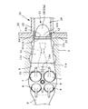
【図2】この第1実施例の吸気装置を上方から見た平面図。
【図3】第1実施例の構成を模式的に示した構成説明図。
【図4】この吸気装置における吸気の流れを示す説明図。
【図5】比較例の吸気装置における吸気の流れを示す説明図。
【図6】タンブルの強さと吸入空気量との関係を示す特性図。
【図7】弁体の傾斜角が大小異なる場合のタンブル強さと間隙の大きさとの関係を示す特性図。
【図8】この発明に係る吸気装置の第2実施例を示す断面図。
【図9】この第2実施例の吸気装置を上方から見た平面図。
【図10】この発明に係る吸気装置の第3実施例を示す断面図。
【図11】この第3実施例の吸気装置を上方から見た平面図。
【符号の説明】
3…シリンダヘッド
5…吸気ポート
7…吸気弁
11…隔壁
12…間隙
21…吸気マニホルド
31…吸気制御弁[0001]
BACKGROUND OF THE INVENTION
The present invention relates to an intake device for an internal combustion engine that includes an intake port connected to a cylinder, and more particularly to an improvement of an intake device that enhances gas flow such as tumble and swirl in the cylinder.
[0002]
[Prior art]
For example, in order to realize stable combustion in a spark ignition type internal combustion engine, gas flow in a cylinder such as tumble or swirl is very important, and it is necessary to be able to enhance gas flow in a wider operating range.
[0003]
One of the conventionally known methods for enhancing the gas flow in the cylinder is to use an intake control valve that shields a part of the passage cross section of the intake port, and In this method, the flowing intake air flow is shifted to one side of the intake port. For example, in order to generate a tumble, an intake control valve is disposed below the intake port, and intake air is shifted toward the upper side of the intake port, whereby the tumble in the cylinder is strengthened.
[0004]
As another method for enhancing the gas flow, as seen in
[0005]
[Patent Document 1]
Japanese Patent Laid-Open No. 2002-54535
[Patent Document 2]
Japanese Patent Application Laid-Open No. 6-1559079
[Problems to be solved by the invention]
In any of the known methods as described above, the passage cross-sectional area of the intake port is substantially reduced by an intake control valve or the like at the time of gas flow enhancement, so that an effective passage for the base intake port cross-sectional area is obtained. When the ratio of the cross-sectional area is defined as “opening ratio”, generally, the smaller the opening ratio, the higher the gas flow. However, if the aperture ratio is small, the ventilation resistance increases, and the amount of intake air that can be sucked into the cylinder decreases. Therefore, the operating conditions that can close the intake control valve and the like to enhance the gas flow are relatively narrow. Limited to range.
[0008]
An object of the present invention is to provide an intake device for an internal combustion engine that can enhance gas flow in a cylinder without excessively reducing the aperture ratio.
[0009]
[Means for Solving the Problems]
In this invention, an intake manifold-side branch section passage is connected to an intake port inside a cylinder head of an internal combustion engine so that an intake passage leading to each cylinder is formed, and a downstream end of the intake port is connected to an intake valve. Assuming an intake device for an internal combustion engine that opens and closes, a partition provided along the longitudinal direction of the intake port so as to partition the intake port into two regions in its cross section, and one partition defined by the partition An intake control valve that opens and closes the flow path. The intake control valve is a rotatable plate-like valve body having a rotation shaft on the intake manifold side, and is positioned at the downstream end of the branch passage near the upstream end of the partition wall. Furthermore, in the present invention, in the closed position where the intake control valve shields the one flow path, a communication path between the two flow paths is formed between the upstream end of the partition wall and the valve body. , A gap is provided.
The rotation shaft of the intake control valve is located on an extension line of the partition wall. The valve body has a main valve portion extending from the rotary shaft to one side so as to shield one flow path in the closed position, and an extended portion extending from the rotary shaft to the opposite side to the main valve portion. This extension portion protrudes toward the other channel in the closed position . As a result, the gap is formed in a straight line having a constant width between the straight edge of the extension and the upstream edge of the partition wall which is also in the same straight line. Moreover , in the open position, it is located in the gap so as to narrow the gap. When the intake control valve is in a closed position where one flow path is shielded, the valve body is inclined in a direction to guide the intake flow to the other flow path, and the main valve portion rotates. A region on the side of one flow path from the shaft is blocked, and a local pressure drop generated downstream of the extension portion causes a gap from one shielded flow path to the other open flow path through the gap. The intake air is recirculated .
[0010]
In the present invention, when the intake control valve is in the closed position where one of the flow paths is shielded, the intake air flows to the cylinder side only through the other flow path. A relatively large amount of intake air flows into the cylinder. At the same time, when the intake control valve throttles the intake flow, a local pressure drop occurs on the downstream side of the intake control valve. This is the outlet side of the gap serving as the communication path (the side facing the other flow path). Act on. Accordingly, a pressure difference is generated between the downstream end portion of the one flow path shielded by the intake control valve and the gap, and the intake air is sucked from the end portion and toward the upstream side of the intake port. On the contrary, it flows and merges into the other channel through the gap. That is, a part of the intake air returns to the upstream side through the shielded flow path. Therefore, the flow rate or flow velocity imbalance of the intake flow passing around the intake valve is further increased, and the gas flow in the cylinder is effectively enhanced.
[0011]
In particular, in the present invention, a partition wall is formed on the cylinder head side in the intake passage leading to each cylinder, and an intake control valve is disposed on the branch portion side of the intake manifold, thereby providing a communication path therebetween. A gap is secured. Therefore, it becomes easy to configure the partition and the intake control valve in a predetermined positional relationship with sufficient accuracy while minimizing the complexity of the configuration.
[0012]
【The invention's effect】
According to the intake device for an internal combustion engine according to the present invention, part of the intake air recirculates through the flow path shielded by the intake control valve, thereby effectively improving the gas flow in the cylinder. A stronger gas flow can be obtained without reducing the opening ratio of the intake control valve. Accordingly, an increase in pumping loss due to an increase in ventilation resistance is suppressed, and a large amount of intake air flowing into the cylinder can be secured, so that the gas flow can be strengthened in a wide operating range.
[0013]
In addition, according to the present invention, the partition wall is disposed on the cylinder head side and the intake control valve is disposed on the intake manifold side, so that the intake air having the partition wall and the intake control valve is minimized while minimizing the complexity of the configuration. The apparatus can be realized, and the required gap accuracy between them can be obtained with high accuracy.
[0014]
DETAILED DESCRIPTION OF THE INVENTION
Hereinafter, preferred embodiments of the present invention will be described in detail with reference to the drawings.
[0015]
FIGS. 1 and 2 show a first embodiment in which the present invention is applied to an intake device of a port injection type spark ignition internal combustion engine, which is an example in which tumble is strengthened as a gas flow. A plurality of
[0016]
As shown in FIG. 1, in this embodiment, a
[0017]
By providing the
[0018]
As will be apparent to those skilled in the art, the terms “upper” and “lower” for the
[0019]
The
[0020]
An intake control valve is provided for each cylinder so as to shield the lower
[0021]
The rotating
[0022]
On the other hand, in an operating condition where the intake air amount is large, for example, in a high speed and high load range, the
[0023]
In this embodiment, the
[0024]
A
[0025]
Although not shown, this internal combustion engine includes a known exhaust gas recirculation device including an exhaust gas recirculation control valve and the like in order to recirculate part of the exhaust gas from the exhaust system to the intake system. By using tumble actively and realizing stable combustion under a high exhaust gas recirculation rate, the fuel consumption is reduced in the partial load range. The recirculated exhaust gas may be introduced collectively into a collector section (not shown) of the
[0026]
Next, the operation of the configuration of the above embodiment will be described using the explanatory diagram of FIG. In the intake stroke, when the
[0027]
On the other hand, when the
[0028]
The strong tumble formed in the
[0029]
In particular, in the above embodiment, since the
[0030]
When the
[0031]
FIG. 4 is an analysis of the actual flow of intake air in the intake system of the above embodiment, and shows the flow speed and direction of each part with fine vectors, that is, arrows. The density of the arrows indicates the flow rate, and the portion where the arrows are gathered densely means that the flow rate is large. Further, FIG. 5 shows the flow of intake air in the same manner as a comparative example with the
[0032]
As is clear from comparison of these figures, in the comparative example of FIG. 5, the intake air flow that has passed through the upper
[0033]
FIG. 6 shows the relationship between the tumble strength and the intake air amount in the intake device using the
[0034]
Therefore, as described above, as a fuel efficiency improvement means, an operation in which a large amount of exhaust gas recirculation and strong tumble can be combined can be performed in a wider operating region, and the fuel efficiency can be greatly improved as a whole internal combustion engine. When compared in the same operation region, tumble is generated more strongly, so that a larger amount of exhaust gas recirculation is possible, and fuel efficiency can be further improved.
[0035]
Thus, although effective tumble reinforcement can be achieved by the
[0036]
Furthermore, in this embodiment, the
[0037]
Further, as shown in FIG. 1, since the inclination angle α of the
[0038]
Next, FIGS. 8 and 9 show a second embodiment of the present invention. In this embodiment, the
[0039]
Next, FIGS. 10 and 11 show a third embodiment of the present invention. In this embodiment, the
[0040]
In each of the above embodiments, the
[Brief description of the drawings]
FIG. 1 is a cross-sectional view showing a first embodiment of an intake device according to the present invention.
FIG. 2 is a plan view of the intake device of the first embodiment as viewed from above.
FIG. 3 is a configuration explanatory diagram schematically showing the configuration of the first embodiment.
FIG. 4 is an explanatory diagram showing the flow of intake air in the intake device.
FIG. 5 is an explanatory diagram showing the flow of intake air in an intake device of a comparative example.
FIG. 6 is a characteristic diagram showing the relationship between tumble strength and intake air amount.
FIG. 7 is a characteristic diagram showing the relationship between tumble strength and gap size when the inclination angle of the valve body is different.
FIG. 8 is a sectional view showing a second embodiment of the intake device according to the present invention.
FIG. 9 is a plan view of the intake device of the second embodiment as viewed from above.
FIG. 10 is a cross-sectional view showing a third embodiment of the intake device according to the present invention.
FIG. 11 is a plan view of the intake device of the third embodiment as viewed from above.
[Explanation of symbols]
3 ...
Claims (7)
上記吸気ポートをその断面で2つの領域に区画するように、吸気ポートの長手方向に沿って設けられた隔壁と、
上記吸気マニホルド側に回転軸を有する回動可能な板状の弁体からなり、上記隔壁の上流端に近接して上記ブランチ部通路の下流端部に位置するとともに、上記隔壁により区画された一方の流路を開閉する吸気制御弁と、
を備え、
さらに、上記吸気制御弁が上記一方の流路を遮蔽した閉位置において、上記隔壁の上流端と上記弁体との間に、間隙が設けられているとともに、
上記吸気制御弁の上記回転軸が、上記隔壁の延長線上に位置し、
上記弁体は、その閉位置において一方の流路を遮蔽するように回転軸から一方へ延びた主弁部を有するとともに、回転軸から上記主弁部とは反対側へ延びた延長部を有し、この延長部が、閉位置においては、他方の流路側に突出し、該延長部の直線状をなす先端縁と同じく直線状をなす上記隔壁上流端縁との間で上記間隙が一定幅の直線状に形成され、かつ、開位置においては、上記間隙を狭めるように間隙内に位置し、
上記吸気制御弁が一方の流路を遮蔽した閉位置にあるときに、上記弁体が、吸気流を他方の流路へ案内する方向に傾斜しているとともに、上記主弁部が回転軸よりも一方の流路の側の領域を塞いでおり、上記延長部の下流に生じる局部的な圧力低下により上記間隙を介して一方の遮蔽された流路から他方の開放された流路へ吸気が還流するように構成されたことを特徴とする内燃機関の吸気装置。An internal combustion engine in which a branch passage on the intake manifold side is continuous with an intake port inside a cylinder head of the internal combustion engine, thereby forming an intake passage leading to each cylinder, and an intake valve opening and closing a tip on the downstream side of the intake port In the intake system of the engine,
A partition wall provided along the longitudinal direction of the intake port so as to divide the intake port into two regions in its cross section;
One of the plate-shaped valve bodies having a rotation shaft on the intake manifold side, located near the upstream end of the partition wall, at the downstream end of the branch passage, and partitioned by the partition wall An intake control valve for opening and closing the flow path of
With
Further, in the closed position where the intake control valve shields the one flow path, a gap is provided between the upstream end of the partition wall and the valve body, and
The rotation axis of the intake control valve is located on an extension of the partition;
The valve body has a main valve portion extending from the rotation shaft to one side so as to shield one flow path at the closed position, and an extension portion extending from the rotation shaft to the opposite side to the main valve portion. In the closed position, the extended portion protrudes toward the other flow path, and the gap has a constant width between the straight end edge of the extended portion and the upstream end edge of the partition wall that is linear. It is formed in a straight line, and in the open position, it is located in the gap so as to narrow the gap,
When the intake control valve is in a closed position where one of the flow paths is shielded, the valve body is inclined in a direction to guide the intake flow to the other flow path, and the main valve portion is rotated from the rotating shaft. The other side of the flow path is closed, and a local pressure drop that occurs downstream of the extension portion causes intake air to flow from one shielded flow path to the other open flow path via the gap. An intake device for an internal combustion engine, characterized by being configured to recirculate .
Priority Applications (6)
| Application Number | Priority Date | Filing Date | Title |
|---|---|---|---|
| JP2003100196A JP3835423B2 (en) | 2003-04-03 | 2003-04-03 | Intake device for internal combustion engine |
| EP04008099A EP1464805B1 (en) | 2003-04-03 | 2004-04-02 | Intake apparatus for internal combustion engine |
| US10/816,001 US7051702B2 (en) | 2003-04-03 | 2004-04-02 | Intake apparatus for internal combustion engine |
| KR1020040022754A KR100608182B1 (en) | 2003-04-03 | 2004-04-02 | Intake apparatus for internal combustion engine |
| DE602004013866T DE602004013866D1 (en) | 2003-04-03 | 2004-04-02 | Air intake device for internal combustion engine |
| CNB2004100333542A CN100335753C (en) | 2003-04-03 | 2004-04-02 | Air inlet device for internal combustion engine |
Applications Claiming Priority (1)
| Application Number | Priority Date | Filing Date | Title |
|---|---|---|---|
| JP2003100196A JP3835423B2 (en) | 2003-04-03 | 2003-04-03 | Intake device for internal combustion engine |
Publications (2)
| Publication Number | Publication Date |
|---|---|
| JP2004308468A JP2004308468A (en) | 2004-11-04 |
| JP3835423B2 true JP3835423B2 (en) | 2006-10-18 |
Family
ID=33464396
Family Applications (1)
| Application Number | Title | Priority Date | Filing Date |
|---|---|---|---|
| JP2003100196A Expired - Lifetime JP3835423B2 (en) | 2003-04-03 | 2003-04-03 | Intake device for internal combustion engine |
Country Status (1)
| Country | Link |
|---|---|
| JP (1) | JP3835423B2 (en) |
Families Citing this family (3)
| Publication number | Priority date | Publication date | Assignee | Title |
|---|---|---|---|---|
| JP4529746B2 (en) * | 2005-03-17 | 2010-08-25 | 日産自動車株式会社 | Intake device for internal combustion engine |
| JP2007247505A (en) * | 2006-03-15 | 2007-09-27 | Nissan Motor Co Ltd | Air intake passage structure for internal combustion engine |
| WO2017119300A1 (en) * | 2016-01-06 | 2017-07-13 | 本田技研工業株式会社 | Internal combustion engine |
-
2003
- 2003-04-03 JP JP2003100196A patent/JP3835423B2/en not_active Expired - Lifetime
Also Published As
| Publication number | Publication date |
|---|---|
| JP2004308468A (en) | 2004-11-04 |
Similar Documents
| Publication | Publication Date | Title |
|---|---|---|
| JP3903942B2 (en) | Intake device for internal combustion engine | |
| JP3829818B2 (en) | Intake device for internal combustion engine | |
| JP4045915B2 (en) | Intake device for internal combustion engine | |
| EP1464805B1 (en) | Intake apparatus for internal combustion engine | |
| US6918372B2 (en) | Intake system of internal combustion engine | |
| JP3861789B2 (en) | Intake device for internal combustion engine | |
| US6213090B1 (en) | Engine cylinder head | |
| JP3835423B2 (en) | Intake device for internal combustion engine | |
| JP3861838B2 (en) | Intake device for internal combustion engine | |
| JP3861837B2 (en) | Intake device for internal combustion engine | |
| JP3832445B2 (en) | Intake device for internal combustion engine | |
| JP3903941B2 (en) | Intake device for internal combustion engine | |
| JP2004324593A (en) | Air-intake system of internal combustion engine | |
| JPH11294266A (en) | Exhaust gas recirculation device | |
| JP6481410B2 (en) | Intake device for internal combustion engine | |
| JP3885320B2 (en) | Engine intake port structure | |
| JP2005291140A (en) | Intake device for internal combustion engine | |
| JP2007309275A (en) | Intake device for internal combustion engine | |
| JPH061054B2 (en) | Internal combustion engine intake system | |
| JP2005054603A (en) | Intake flow control valve | |
| JPH0913977A (en) | Intake system for internal combustion engine |
Legal Events
| Date | Code | Title | Description |
|---|---|---|---|
| A131 | Notification of reasons for refusal |
Free format text: JAPANESE INTERMEDIATE CODE: A131 Effective date: 20050726 |
|
| A521 | Request for written amendment filed |
Free format text: JAPANESE INTERMEDIATE CODE: A523 Effective date: 20050908 |
|
| A02 | Decision of refusal |
Free format text: JAPANESE INTERMEDIATE CODE: A02 Effective date: 20060124 |
|
| A521 | Request for written amendment filed |
Free format text: JAPANESE INTERMEDIATE CODE: A523 Effective date: 20060327 |
|
| A521 | Request for written amendment filed |
Free format text: JAPANESE INTERMEDIATE CODE: A523 Effective date: 20060502 |
|
| A911 | Transfer to examiner for re-examination before appeal (zenchi) |
Free format text: JAPANESE INTERMEDIATE CODE: A911 Effective date: 20060510 |
|
| TRDD | Decision of grant or rejection written | ||
| A01 | Written decision to grant a patent or to grant a registration (utility model) |
Free format text: JAPANESE INTERMEDIATE CODE: A01 Effective date: 20060704 |
|
| A61 | First payment of annual fees (during grant procedure) |
Free format text: JAPANESE INTERMEDIATE CODE: A61 Effective date: 20060717 |
|
| R150 | Certificate of patent or registration of utility model |
Ref document number: 3835423 Country of ref document: JP Free format text: JAPANESE INTERMEDIATE CODE: R150 Free format text: JAPANESE INTERMEDIATE CODE: R150 |
|
| FPAY | Renewal fee payment (event date is renewal date of database) |
Free format text: PAYMENT UNTIL: 20090804 Year of fee payment: 3 |
|
| FPAY | Renewal fee payment (event date is renewal date of database) |
Free format text: PAYMENT UNTIL: 20100804 Year of fee payment: 4 |
|
| R250 | Receipt of annual fees |
Free format text: JAPANESE INTERMEDIATE CODE: R250 |
|
| FPAY | Renewal fee payment (event date is renewal date of database) |
Free format text: PAYMENT UNTIL: 20110804 Year of fee payment: 5 |
|
| FPAY | Renewal fee payment (event date is renewal date of database) |
Free format text: PAYMENT UNTIL: 20120804 Year of fee payment: 6 |
|
| FPAY | Renewal fee payment (event date is renewal date of database) |
Free format text: PAYMENT UNTIL: 20120804 Year of fee payment: 6 |
|
| FPAY | Renewal fee payment (event date is renewal date of database) |
Free format text: PAYMENT UNTIL: 20130804 Year of fee payment: 7 |
|
| FPAY | Renewal fee payment (event date is renewal date of database) |
Free format text: PAYMENT UNTIL: 20140804 Year of fee payment: 8 |
|
| EXPY | Cancellation because of completion of term |