JP3827671B2 - Linear motor - Google Patents
Linear motor Download PDFInfo
- Publication number
- JP3827671B2 JP3827671B2 JP2003413356A JP2003413356A JP3827671B2 JP 3827671 B2 JP3827671 B2 JP 3827671B2 JP 2003413356 A JP2003413356 A JP 2003413356A JP 2003413356 A JP2003413356 A JP 2003413356A JP 3827671 B2 JP3827671 B2 JP 3827671B2
- Authority
- JP
- Japan
- Prior art keywords
- cores
- shaped
- winding
- ring
- gap
- Prior art date
- Legal status (The legal status is an assumption and is not a legal conclusion. Google has not performed a legal analysis and makes no representation as to the accuracy of the status listed.)
- Expired - Fee Related
Links
Images


Landscapes
- Linear Motors (AREA)
Description
本発明は、リニアモータに関し、特に、輪状巻線に対して各コアを隙間を介して独立配置することにより、漏れ磁束を減らし、高効率に推力を得るための新規な改良に関する。 The present invention relates to a linear motor, and more particularly to a novel improvement for obtaining a thrust with high efficiency by reducing leakage flux by independently disposing each core through a gap with respect to a ring-shaped winding.
従来、用いられていたこの種のリニアモータとしては、特許文献1に開示された図5の構成、特許文献2に開示された図6の構成、特許文献3に開示された図7から図11の構成を挙げることができる。 Conventionally used linear motors of this type include the configuration of FIG. 5 disclosed in Patent Document 1, the configuration of FIG. 6 disclosed in Patent Document 2, and FIGS. 7 to 11 disclosed in Patent Document 3. The structure of can be mentioned.
図5の第1従来構成においては、ベース1上に片側磁石ユニット2、3、4、5が設けられ、各々輪状巻線6、7、8、9が設けられている。
一対の前記磁石ユニット2、4及び3、5によって1対の固定子ユニット10、11が形成されて固定子12が構成されている。
In the first conventional configuration of FIG. 5, one-side magnet units 2, 3, 4, and 5 are provided on a base 1, and ring-
The pair of magnet units 2, 4, 3, 5 forms a pair of stator units 10, 11 to form a stator 12.
前記各片側磁石ユニット2〜5は、互いに交互に配設された複数の第1コア20及び第2コア21で構成され、各第1コア20及び第2コア21に形成された空隙22内に、複数のマグネット23を有する可動子24が往復動自在に設けられている。
Each of the one-side magnet units 2 to 5 is composed of a plurality of
また、図6の第2従来構成の場合、電機子巻線8を有する電機子10には、第1、第2コア20、21が交互に設けられ、この第1、第2コア20、21と電機子巻線8との間には、複数のマグネット23を有する可動子24が往復動自在に配設されている。
Further, in the case of the second conventional configuration of FIG. 6, the armature 10 having the armature winding 8 is provided with first and
また、図7から図11で示される第3従来構成の場合、垂直方向に端面を配設した輪状巻線8に対し、図8に示す複数の磁極歯20aを上下に各々一体に有する磁極歯列状の第1コア20と、図9に示す複数の磁極歯21a(前記磁極歯20aよりも高さが大きく形成されている)を上下に各々一体に有する磁極歯列状の第2コア21が図10のように、長手方向に重合し、かつ、各磁極歯20a、21aが交互に配設されている。
前記各磁極歯20a、21aに形成されたスリット状の空隙22は直線状に整列され、この空隙22には複数のマグネット23を有する可動子24が往復動自在に配設されている。
Further, in the case of the third conventional configuration shown in FIGS. 7 to 11, a magnetic pole tooth having a plurality of
The slit-
従来のリニアモータは、以上のように構成されていたため、次のような課題が存在していた。
すなわち、図5の第1従来構成の場合、1相分の構成において可動子の両側に一対の輪状巻線を設けなければならず、構成が複雑で、大量生産には不向きであった。
Since the conventional linear motor is configured as described above, the following problems exist.
That is, in the case of the first conventional configuration in FIG. 5, a pair of ring-shaped windings must be provided on both sides of the mover in the configuration for one phase, and the configuration is complicated and unsuitable for mass production.
また、図6の第2従来構成の場合、可動子は電機子の各コア間の閉じた形状の空洞内に配設されているため、可動子と電機子の組立が難しく、さらに、可動子が偏平状となるため、構造的に強度不足となり、移動方向に長く形成することが困難であった。 In the case of the second conventional configuration shown in FIG. 6, since the mover is disposed in a closed cavity between the cores of the armature, it is difficult to assemble the mover and the armature. Because of the flat shape, the structure is insufficient in strength, and it is difficult to form it long in the moving direction.
また、図7から図11迄の第3従来構成の場合、構成としては本願発明の構成には近いと云えるが、各コアの各磁極歯が全く一体状に形成されているため、図11の太線で示すように、漏れ磁束φ0が発生しやすく、可動子との間で生じる電機子反作用(アマチュアリアクション)も加わり、可動子が移動する空隙のギャップの磁力が大幅に減少し、推力、動作効率を向上させることは極めて困難であった。 Further, in the case of the third conventional configuration shown in FIGS. 7 to 11, it can be said that the configuration is similar to the configuration of the present invention. However, since the magnetic pole teeth of each core are formed integrally, FIG. As shown by the thick line, leakage flux φ 0 is likely to occur, armature reaction (amateur reaction) that occurs with the mover is added, the magnetic force of the gap gap where the mover moves is greatly reduced, thrust It has been extremely difficult to improve the operation efficiency.
本発明によるリニアモータは、輪状に形成された1個の輪状巻線と、前記輪状巻線に設けられ空隙を有する合計4個の第1、第2コアと、からなる固定子部を複数個用いて固定子を形成し、前記第1、第2コアの各空隙内にマグネットを有する可動子が往復動するように構成したリニアモータにおいて、
前記第1、第2コアはU字部とL字部の連続一体形状よりなり、1個の前記輪状巻線で1相が形成され、前記輪状巻線の互いに離間して対向する第1、第2直線部に各々2個ずつ前記第1、第2コアが互いに独立した状態でかつ前記第1、第2直線部の長手方向に沿って前記U字部とL字部が直接重合して配設され、前記第1、第2コアの各第1、第2コア面には前記輪状巻線が存在せず、前記第1、第2コアの前記第1、第2コア面と対向する第3、第4コア面には1個の空隙が上方へ向けて解放された状態で形成され、断面T字型をなす前記可動子の一端に設けられた支持板は前記輪状巻線の端面と平面でみて重合し、前記可動子の一列のマグネットのみが前記空隙内に位置している構成であり、また、前記固定子は、2相又は3相とした構成である。
The linear motor according to the present invention includes a plurality of stator portions each including a ring-shaped winding formed in a ring shape and a total of four first and second cores provided in the ring-shaped winding and having gaps. In a linear motor configured to form a stator, and a movable element having a magnet reciprocally moves in each gap of the first and second cores,
The first and second cores are formed by continuously integrating a U-shaped portion and an L-shaped portion, and one phase is formed by one of the ring-shaped windings, and the first and second of the ring-shaped windings facing each other apart from each other. Two U-shaped portions and two L-shaped portions are directly superposed along the longitudinal direction of the first and second linear portions in a state where the first and second cores are each two in the second linear portion. The first and second core surfaces of the first and second cores do not have the ring-shaped windings and are opposed to the first and second core surfaces of the first and second cores. A support plate provided at one end of the mover having a T-shaped cross section is formed on the third and fourth core surfaces in a state where one gap is released upward, and is an end surface of the ring-shaped winding. And only one row of magnets is positioned in the gap, and the stator has two or three phases. It is a configuration.
本発明によるリニアモータは、以上のように構成されているため、次のような効果を得ることができる。
すなわち、1相当り1個の輪状巻線であるため、1相ユニットが小さくできる。
また、固定子と可動子が完全に分離されているため、製作及び組立が容易であり、断面T字型の可動子であるため、従来よりも強度が高く、長さの制限を受けることもない。
また、輪状巻線に設ける各コアが全て独立して配設されているため、従来よりも漏れ磁束を大幅に少なくし、極間隙間を詰め極幅を広くすることにより効率を向上させることができる。また、可動子を断面T字型とし、剛性を向上させ、長手形状が作りやすくなる。
Since the linear motor according to the present invention is configured as described above, the following effects can be obtained.
That is, since one ring winding corresponds to one, the one-phase unit can be made small.
In addition, since the stator and the mover are completely separated, the manufacture and assembly are easy, and since the mover has a T-shaped cross section, the strength is higher than the conventional one and the length is limited. Absent.
In addition, since all the cores provided in the ring-shaped winding are all independently arranged, it is possible to improve efficiency by significantly reducing the leakage magnetic flux compared to the prior art, filling the gap between the poles, and widening the pole width. it can. Further, the mover has a T-shaped cross section, which improves the rigidity and makes it easier to make a longitudinal shape.
本発明は、輪状巻線に対して複数のコアを独立し、かつ、交互に互いに重合するように配設して漏れ磁束を少なくし、効率を向上させることを目的とする。 It is an object of the present invention to reduce the leakage magnetic flux by arranging a plurality of cores independently from each other with respect to the ring-shaped winding so as to overlap each other, thereby improving the efficiency.
以下、図面と共に本発明によるリニアモータの好適な実施の形態について説明する。尚、従来例と同一又は同等部分には同一符号を用いて説明する。
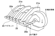
図1において符号8で示されるものは輪状に形成されたA相用の第1輪状巻線であり、この第1輪状巻線8の一対の互いに離間して対向する第1、第2直線部8A、8Bには複数の第1、第2コア20、21が所定の間隔で、かつ、完全に独立して設けられている。前記各コア20、21は、U字部(U)とL字部(L)が連続して一体の形状で形成されている。
Hereinafter, preferred embodiments of a linear motor according to the present invention will be described with reference to the drawings. The same reference numerals are used for the same or equivalent parts as in the conventional example.
In FIG. 1,
前記第1、第2コア20、21は、第1輪状巻線8の各直線部8A、8Bの長手方向に沿って互いに交互に、かつ、前記長手方向に沿って重合するように配設されている。すなわち、前記U字部(U)とL字部(L)とが直接重合している。
前記第1輪状巻線8の隣接位置には、B相用として、第2輪状巻線9が直線状位置に配設されている。
The first,
At the position adjacent to the first ring-
前記第1、第2コア20、21の各第1、第2コア面20a、21a(図3の底面に相当)には第1輪状巻線8が存在せず、前記第1、第2コア20a、21aと対向する第3、第4コア面20b、21b(図3の上面に相当)には、上方へ向けて解放された状態の空隙22が形成されている。このスリット状の1個の空隙22は、直線状に配列され、この空隙22内には、複数のマグネット23を直線状でかつ板状に有すると共に交互にN、S着磁した可動子24が往復動自在に設けられている。
前記可動子24は、各マグネット23を支持する長手板状の支持板24Aを有しており、全体形状としては断面T字型をなす高剛性を有する構造で形成されると共に、前記各輪状巻線8、9の端面8Dの面方向と平行に往復動できる構成である。また、前記可動子24の一端に設けられた支持板24Aは、前記輪状巻線8の端面8Dと平面でみて重合し、前記可動子24のマグネット23のみが前記空隙22内に位置している。
尚、第1輪状巻線8と各コア20、21によって固定子部50が形成され、複数の固定子部50を各相分ベース1上に固定することにより固定子12が形成されている。
The first and
The mover 24 has a longitudinal plate-like support plate 24A that supports each
A stator portion 50 is formed by the first ring-
図2は、図1の構成を平面的に示し、A相、B相、C相からなる三相とした場合を示しており、極間隔G3に対し、各コア20、21間の極間隙間G1を詰めることによって極幅G2を広くすることができる。
FIG. 2 shows the configuration of FIG. 1 in a plan view, and shows a case of three phases including an A phase, a B phase, and a C phase, and a gap between the
図3は、図2の輪状巻線8の通電状態を示すもので、第1、第2コア20、21に流れる磁束φによって可動子24が直動できる状態を示している。
FIG. 3 shows an energized state of the ring-
図4は、本発明のリニアモータの磁路を示すもので、第1輪状巻線8に対して図示の方向によって電流を印加すると、各コア20、21に対して主磁路l0が形成されるが、各コア20、21は一体化されていないため、両側の各コア20に対して2倍の極間隙間G1の空気層を通過する必要があり、磁束が流れにくく、漏れ磁路l1、l2が形成され苦しくなり、可動子24に対する大きい駆動力を得ることができる。
従って、一相、二相又は三相の輪状巻線8、9・・・を用いて駆動電流を制御することにより、周知の磁気作用により可動子24を自在に直動させることができる。
尚、説明の便宜上、コイル側を固定子側、マグネット側を可動子側としたが、固定子側と可動子側を逆にしても成立つことは述べるまでもないことである。
FIG. 4 shows a magnetic path of the linear motor of the present invention. When a current is applied to the first
Therefore, by controlling the drive current using the one-phase, two-phase, or three-phase ring-
For convenience of explanation, the coil side is the stator side, and the magnet side is the mover side. However, it goes without saying that the stator side and the mover side are reversed.
本発明は、リニアモータに限らず、リニアアクチュエータ、リニア検出器等へ適用が可である。 The present invention is applicable not only to linear motors but also to linear actuators, linear detectors, and the like.
1 ベース
8 第1輪状巻線
9 第2輪状巻線
12 固定子
20 第1コア
21 第2コア
22 空隙
23 マグネット
24 可動子
8A、8B 第1、第2直線部
50 固定子部
G1 極間隙間
G2 極幅
G3 極間隔
DESCRIPTION OF SYMBOLS 1
Claims (2)
前記第1、第2コア(20,21)はU字部(U)とL字部(L)の連続一体形状よりなり、1個の前記輪状巻線(8)で1相が形成され、前記輪状巻線(8)の互いに離間して対向する第1、第2直線部(8A,8B)に各々2個ずつ前記第1、第2コア(20,21)が互いに独立した状態でかつ前記第1、第2直線部(8A,8B)の長手方向に沿って前記U字部(U)とL字部(L)が直接重合して配設され、前記第1、第2コア(20,21)の各第1、第2コア面(20a,21a)には前記輪状巻線(8)が存在せず、前記第1、第2コア(20,21)の前記第1、第2コア面(20a,21a)と対向する第3、第4コア面(20b,21b)には1個の空隙(22)が上方へ向けて解放された状態で形成され、断面T字型をなす前記可動子(24)の一端に設けられた支持板(24A)は前記輪状巻線(8)の端面(8D)と平面でみて重合し、前記可動子(24)の一列のマグネット(23)のみが前記空隙(22)内に位置していることを特徴とするリニアモータ。 One annular winding formed annular and (8), the circular winding a total of four first with voids (22) provided in (8), a second core (20, 21), from A stator (12) is formed by using a plurality of stator parts (50), and a mover (26) having a magnet (23) in each gap (22) of the first and second cores (20, 21). 24) in a linear motor configured to reciprocate,
The first and second cores (20, 21) are formed by continuously integrating a U-shaped part (U) and an L-shaped part (L), and one phase is formed by one annular winding (8). Two each of the first and second cores (20, 21) are independent from each other on the first and second linear portions (8A, 8B) of the ring-shaped winding (8) that are spaced apart from each other. The U-shaped portion (U) and the L-shaped portion (L) are directly superposed along the longitudinal direction of the first and second linear portions (8A, 8B), and the first and second cores ( 20, 21) does not have the annular winding (8) on the first and second core surfaces (20a, 21a), and the first and second cores (20, 21) have the first and second core surfaces (20a, 21a). The third and fourth core surfaces (20b, 21b) facing the two core surfaces (20a, 21a) are formed with one gap (22) open upward, and have a T-shaped cross section. A support plate (24A) provided at one end of the movable element (24) is overlapped with the end surface (8D) of the ring-shaped winding (8) when viewed in plan, and a single row of magnets (23 ) Only the linear motor is located in the gap (22).
Priority Applications (1)
| Application Number | Priority Date | Filing Date | Title |
|---|---|---|---|
| JP2003413356A JP3827671B2 (en) | 2003-12-11 | 2003-12-11 | Linear motor |
Applications Claiming Priority (1)
| Application Number | Priority Date | Filing Date | Title |
|---|---|---|---|
| JP2003413356A JP3827671B2 (en) | 2003-12-11 | 2003-12-11 | Linear motor |
Publications (2)
| Publication Number | Publication Date |
|---|---|
| JP2005176506A JP2005176506A (en) | 2005-06-30 |
| JP3827671B2 true JP3827671B2 (en) | 2006-09-27 |
Family
ID=34733508
Family Applications (1)
| Application Number | Title | Priority Date | Filing Date |
|---|---|---|---|
| JP2003413356A Expired - Fee Related JP3827671B2 (en) | 2003-12-11 | 2003-12-11 | Linear motor |
Country Status (1)
| Country | Link |
|---|---|
| JP (1) | JP3827671B2 (en) |
Families Citing this family (2)
| Publication number | Priority date | Publication date | Assignee | Title |
|---|---|---|---|---|
| DE102013014248A1 (en) * | 2013-08-27 | 2015-03-05 | Herbert Weh | Electric linear drive for road traffic |
| JP7344813B2 (en) * | 2020-02-25 | 2023-09-14 | 株式会社日立産機システム | Linear motors, compressors equipped with linear motors, refrigerators equipped with these compressors, and air suspensions for vehicles |
-
2003
- 2003-12-11 JP JP2003413356A patent/JP3827671B2/en not_active Expired - Fee Related
Also Published As
| Publication number | Publication date |
|---|---|
| JP2005176506A (en) | 2005-06-30 |
Similar Documents
| Publication | Publication Date | Title |
|---|---|---|
| KR100443590B1 (en) | Linear motor and production method therefor | |
| US6548920B2 (en) | Linear motor and method of producing the same | |
| EP1330864B1 (en) | Xyz-axes table | |
| JP5477126B2 (en) | Linear motor | |
| JP3945142B2 (en) | Linear motor and control method thereof | |
| JP5770417B2 (en) | Linear motor | |
| JP2010183823A (en) | Linear motor | |
| JP3360606B2 (en) | Linear motor | |
| JP2009219199A (en) | Linear motor | |
| JP3855914B2 (en) | Linear drive | |
| JP4061835B2 (en) | Electric motor | |
| JP3744437B2 (en) | Drive device | |
| JP5386925B2 (en) | Cylindrical linear motor | |
| JP5678025B2 (en) | Thrust generating mechanism | |
| JP3827671B2 (en) | Linear motor | |
| JP4089597B2 (en) | Linear motor and XY stage | |
| JPH0823669A (en) | Linear actuator | |
| JP3944766B2 (en) | Permanent magnet synchronous linear motor | |
| KR20130008725A (en) | Electric motor | |
| JP4106571B2 (en) | Linear motor | |
| JP3906443B2 (en) | Linear motor | |
| JP4458078B2 (en) | Linear motor and control method thereof | |
| JP2005229778A (en) | Linear motor | |
| JP2007143398A (en) | Linear motor | |
| JP2007209175A (en) | Three-phase linear motor |
Legal Events
| Date | Code | Title | Description |
|---|---|---|---|
| A977 | Report on retrieval |
Free format text: JAPANESE INTERMEDIATE CODE: A971007 Effective date: 20051221 |
|
| A131 | Notification of reasons for refusal |
Free format text: JAPANESE INTERMEDIATE CODE: A131 Effective date: 20060110 |
|
| A521 | Written amendment |
Free format text: JAPANESE INTERMEDIATE CODE: A523 Effective date: 20060217 |
|
| TRDD | Decision of grant or rejection written | ||
| A01 | Written decision to grant a patent or to grant a registration (utility model) |
Free format text: JAPANESE INTERMEDIATE CODE: A01 Effective date: 20060627 |
|
| A61 | First payment of annual fees (during grant procedure) |
Free format text: JAPANESE INTERMEDIATE CODE: A61 Effective date: 20060704 |
|
| R150 | Certificate of patent or registration of utility model |
Free format text: JAPANESE INTERMEDIATE CODE: R150 |
|
| LAPS | Cancellation because of no payment of annual fees |