JP3822041B2 - Vehicle bearing device - Google Patents
Vehicle bearing device Download PDFInfo
- Publication number
- JP3822041B2 JP3822041B2 JP2000262547A JP2000262547A JP3822041B2 JP 3822041 B2 JP3822041 B2 JP 3822041B2 JP 2000262547 A JP2000262547 A JP 2000262547A JP 2000262547 A JP2000262547 A JP 2000262547A JP 3822041 B2 JP3822041 B2 JP 3822041B2
- Authority
- JP
- Japan
- Prior art keywords
- shaft portion
- vehicle
- hub wheel
- constant velocity
- velocity joint
- Prior art date
- Legal status (The legal status is an assumption and is not a legal conclusion. Google has not performed a legal analysis and makes no representation as to the accuracy of the status listed.)
- Expired - Fee Related
Links
Images


Classifications
-
- F—MECHANICAL ENGINEERING; LIGHTING; HEATING; WEAPONS; BLASTING
- F16—ENGINEERING ELEMENTS AND UNITS; GENERAL MEASURES FOR PRODUCING AND MAINTAINING EFFECTIVE FUNCTIONING OF MACHINES OR INSTALLATIONS; THERMAL INSULATION IN GENERAL
- F16C—SHAFTS; FLEXIBLE SHAFTS; ELEMENTS OR CRANKSHAFT MECHANISMS; ROTARY BODIES OTHER THAN GEARING ELEMENTS; BEARINGS
- F16C35/00—Rigid support of bearing units; Housings, e.g. caps, covers
- F16C35/04—Rigid support of bearing units; Housings, e.g. caps, covers in the case of ball or roller bearings
- F16C35/06—Mounting or dismounting of ball or roller bearings; Fixing them onto shaft or in housing
- F16C35/063—Fixing them on the shaft
- F16C35/0635—Fixing them on the shaft the bore of the inner ring being of special non-cylindrical shape which co-operates with a complementary shape on the shaft, e.g. teeth, polygonal sections
-
- F—MECHANICAL ENGINEERING; LIGHTING; HEATING; WEAPONS; BLASTING
- F16—ENGINEERING ELEMENTS AND UNITS; GENERAL MEASURES FOR PRODUCING AND MAINTAINING EFFECTIVE FUNCTIONING OF MACHINES OR INSTALLATIONS; THERMAL INSULATION IN GENERAL
- F16C—SHAFTS; FLEXIBLE SHAFTS; ELEMENTS OR CRANKSHAFT MECHANISMS; ROTARY BODIES OTHER THAN GEARING ELEMENTS; BEARINGS
- F16C19/00—Bearings with rolling contact, for exclusively rotary movement
- F16C19/02—Bearings with rolling contact, for exclusively rotary movement with bearing balls essentially of the same size in one or more circular rows
- F16C19/14—Bearings with rolling contact, for exclusively rotary movement with bearing balls essentially of the same size in one or more circular rows for both radial and axial load
- F16C19/18—Bearings with rolling contact, for exclusively rotary movement with bearing balls essentially of the same size in one or more circular rows for both radial and axial load with two or more rows of balls
- F16C19/181—Bearings with rolling contact, for exclusively rotary movement with bearing balls essentially of the same size in one or more circular rows for both radial and axial load with two or more rows of balls with angular contact
- F16C19/183—Bearings with rolling contact, for exclusively rotary movement with bearing balls essentially of the same size in one or more circular rows for both radial and axial load with two or more rows of balls with angular contact with two rows at opposite angles
- F16C19/184—Bearings with rolling contact, for exclusively rotary movement with bearing balls essentially of the same size in one or more circular rows for both radial and axial load with two or more rows of balls with angular contact with two rows at opposite angles in O-arrangement
- F16C19/186—Bearings with rolling contact, for exclusively rotary movement with bearing balls essentially of the same size in one or more circular rows for both radial and axial load with two or more rows of balls with angular contact with two rows at opposite angles in O-arrangement with three raceways provided integrally on parts other than race rings, e.g. third generation hubs
-
- F—MECHANICAL ENGINEERING; LIGHTING; HEATING; WEAPONS; BLASTING
- F16—ENGINEERING ELEMENTS AND UNITS; GENERAL MEASURES FOR PRODUCING AND MAINTAINING EFFECTIVE FUNCTIONING OF MACHINES OR INSTALLATIONS; THERMAL INSULATION IN GENERAL
- F16C—SHAFTS; FLEXIBLE SHAFTS; ELEMENTS OR CRANKSHAFT MECHANISMS; ROTARY BODIES OTHER THAN GEARING ELEMENTS; BEARINGS
- F16C2226/00—Joining parts; Fastening; Assembling or mounting parts
- F16C2226/50—Positive connections
- F16C2226/60—Positive connections with threaded parts, e.g. bolt and nut connections
-
- F—MECHANICAL ENGINEERING; LIGHTING; HEATING; WEAPONS; BLASTING
- F16—ENGINEERING ELEMENTS AND UNITS; GENERAL MEASURES FOR PRODUCING AND MAINTAINING EFFECTIVE FUNCTIONING OF MACHINES OR INSTALLATIONS; THERMAL INSULATION IN GENERAL
- F16C—SHAFTS; FLEXIBLE SHAFTS; ELEMENTS OR CRANKSHAFT MECHANISMS; ROTARY BODIES OTHER THAN GEARING ELEMENTS; BEARINGS
- F16C2326/00—Articles relating to transporting
- F16C2326/01—Parts of vehicles in general
- F16C2326/02—Wheel hubs or castors
-
- F—MECHANICAL ENGINEERING; LIGHTING; HEATING; WEAPONS; BLASTING
- F16—ENGINEERING ELEMENTS AND UNITS; GENERAL MEASURES FOR PRODUCING AND MAINTAINING EFFECTIVE FUNCTIONING OF MACHINES OR INSTALLATIONS; THERMAL INSULATION IN GENERAL
- F16D—COUPLINGS FOR TRANSMITTING ROTATION; CLUTCHES; BRAKES
- F16D3/00—Yielding couplings, i.e. with means permitting movement between the connected parts during the drive
- F16D3/16—Universal joints in which flexibility is produced by means of pivots or sliding or rolling connecting parts
- F16D3/20—Universal joints in which flexibility is produced by means of pivots or sliding or rolling connecting parts one coupling part entering a sleeve of the other coupling part and connected thereto by sliding or rolling members
- F16D3/22—Universal joints in which flexibility is produced by means of pivots or sliding or rolling connecting parts one coupling part entering a sleeve of the other coupling part and connected thereto by sliding or rolling members the rolling members being balls, rollers, or the like, guided in grooves or sockets in both coupling parts
- F16D3/223—Universal joints in which flexibility is produced by means of pivots or sliding or rolling connecting parts one coupling part entering a sleeve of the other coupling part and connected thereto by sliding or rolling members the rolling members being balls, rollers, or the like, guided in grooves or sockets in both coupling parts the rolling members being guided in grooves in both coupling parts
- F16D2003/22326—Attachments to the outer joint member, i.e. attachments to the exterior of the outer joint member or to the shaft of the outer joint member
Landscapes
- Engineering & Computer Science (AREA)
- General Engineering & Computer Science (AREA)
- Mechanical Engineering (AREA)
- Support Of The Bearing (AREA)
- Mounting Of Bearings Or Others (AREA)
- Rolling Contact Bearings (AREA)
Description
【0001】
【発明の属する技術分野】
本発明は、ディスクブレーキ装置のディスクロータおよび車輪が取り付けられる車両用ハブユニット等の車両用軸受装置に関する。
【0002】
【従来の技術】
図11で示される従来の駆動輪用ハブユニットにおいては、車輪が取り付けられるハブホイール1の中空軸部12の外周に複列転がり軸受2が外嵌装着されている。このハブホイール1は、等速ジョイント3により、シャフト7に対して傾動可能に連結される。ハブホイール1の中空軸部12における車両インナ側軸端は、径方向外向きに屈曲変形されてかしめ部12aとされ複列転がり軸受2における内輪25の外端面にかしめつけられることで、その内輪25に対して予圧と抜け止めとが行われる。
【0003】
等速ジョイント3の外輪31は、傾動案内用のボール群の軌道となる椀型の筒部35と、これの小径部分にハブホイール1の中空軸部12に挿入されて該中空軸部12とスプライン嵌合する軸部36とで構成される。
【0004】
等速ジョイント3は、その椀型筒部35がハブホイール1の中空軸部12における車両インナ側軸端を径方向外向きに屈曲変形してなるかしめ部12aに当接されている一方、その外輪軸部36の車両アウタ側の小径ねじ軸部36hに螺合されたナット36iの端面がハブホイール1の中空軸部12の車両アウタ側開口12cの端面12hに宛てがわれた状態で、ナット36iの締結によりハブホイール1に連結されている。
【0005】
【発明が解決しようとする課題】
上記のようなハブユニットの場合、一般に、複列転がり軸受2の内輪25の外端面にハブホイール1の車両インナ側端部をかしめつけることにより、複列転がり軸受2に予圧を付与している。
【0006】
通常、ハブホイール1に等速ジョイント3の外輪31を結合するために、ナット36iは緩みのないよう所要のトルクで締め付けられる。
【0007】
ところで、図11のように、かしめ部12aと、等速ジョイント3の外輪軸部36とを接触させて、椀型筒部36とナット36iとで軸方向から挟む形態とすることにより、ハブホイール1と等速ジョイント3とを結合する構造の場合、締め付けトルクが、複列転がり軸受2に対して余分な負荷としてかかり、前記予圧に影響を及ぼすおそれがある。
【0008】
そこで、本願出願人は、鋭意研究の結果、前記予圧に対してナット36iの締め付けトルクの影響を低減できる構造を考え付き本発明を完成できるに至った。
【0009】
したがって、本発明は、車両用ハブユニット等の軸受装置において、ナットを緩まないよう締め付けても、その締め付けが複列転がり軸受に対する予圧に影響しないようにすることを課題としている。
【0010】
【課題を解決するための手段】
本発明の車両用軸受装置は、車輪が取り付けられるハブホイールの中空軸部の外周に複列転がり軸受が外嵌装着され、また、このハブホイールを駆動軸に対して傾動可能に連結する等速ジョイントを備えた車両用軸受装置であって、ハブホイールの中空軸部における車両インナ側軸端が複列転がり軸受の車両インナ側内輪の外端面にかしめつけられており、等速ジョイントの外輪が、傾動案内用のボール群の軌道となる椀型の筒部とこれの小径部分にハブホイールの中空軸部に挿入されてスプライン嵌合する外輪軸部とを有する構成とされており、前記等速ジョイントの外輪軸部の車両アウタ側軸端にねじ軸部が設けられ、このねじ軸部に対してナットが螺合され、このナットがハブホイールの中空軸部の車両アウタ側端面に当てられることでハブホイールに等速ジョイントの外輪が結合されており、中空軸部の内周面の車両アウタ側端面から軸方向車両インナ側に離れた位置に径方向外方へ拡径された周溝状切欠きを設けて構成されている。
【0020】
【発明の実施の形態】
以下、本発明の詳細を図面に示す実施形態に基づいて説明する。
【0021】
本実施形態は、車両用ハブユニットについて説明するが、本発明はこれに限定されず、車両用の軸受装置に適用することができる。
【0022】
図1ないし図4は、本発明の実施形態に係る車両用ハブユニットを示し、図1は、車両用ハブユニットの縦断側面図、図2は、図1の要部の拡大図、図3は、図2に示されるハブホイールの中空軸部の拡大図、図4は、図2に示される等速ジョイントの外輪軸部の拡大図である。
【0023】
図例の車両用ハブユニットは、自動車の駆動輪側に使用されるタイプであって、ハブホイール1と、複列転がり軸受2と、等速ジョイント3とを備える。
【0024】
ハブホイール1は、不図示の車輪が取り付けられる径方向外向きのフランジ11と、複列転がり軸受2がその外周の軸受嵌合領域に固定される中空軸部12とを有する。ハブホイール1の中空軸部12の外周面の車両アウタ側寄りに複列転がり軸受2における片方列のボール22群の軌道面22aが形成されている。
【0025】
ハブホイール1の中空軸部12の車両インナ側軸端は、径方向外向きに屈曲されて複列転がり軸受2の車両インナ側内輪25の外端面にかしめつけられたかしめ部12aとなっている。
【0026】
複列転がり軸受2は、二列の軌道溝を有する単一の外輪21と、二列で配設される転動体としての複数のボール22と、二つの冠形保持器23とから構成されており、本来必要な2つの内輪については、一方は上述したようにハブホイール1の車両アウタ側の軌道面22aを利用し、車両インナ側の内輪25のみを備えた構成となっている。なお、上記外輪21には、車体6などにボルト止めされる径方向外向きのフランジ24が形成されている。
【0027】
等速ジョイント3は、例えば、周知のツェッパタイプ(バーフィールド型)と呼ばれるものとされ、外輪31、内輪32、ボール33および保持器34などから構成されている。
【0028】
外輪31は、内輪32、ボール33および保持器34などが収納配設される椀形筒部35と、この椀形筒部35の小径側に一体に連接される軸部36とから構成されている。
【0029】
内輪32には、シャフト(駆動軸)7の一端側がスプライン嵌合されるとともに止め輪(符号省略)などで抜け止め固定され、このシャフト7の他端側が、図示しない別の等速ジョイントを介して車両のデファレンシャル装置に取り付けられる。
【0030】
そして、上記ハブホイール1の外周面に複列転がり軸受2を取り付けると共にハブホイール1に対して複列転がり軸受2と近接した状態で等速ジョイント3を取り付ける。
【0031】
また、上記フランジ11の円周数箇所には、ディスクブレーキ装置のディスクロータ4および車輪(図示省略)を固定するためのボルト13が貫通状態で装着されている。
【0032】
このような車両用ハブユニットでは、シャフト7の回転動力が、等速ジョイント3を介してハブホイール1に取り付けられてある車輪(図示省略)に対して伝達される。
【0033】
次に、等速ジョイントの3の外輪31は、かしめ部12aに対して等速ジョイント3の外輪31における椀型筒部35が隙間Gにより非接触となる状態でハブホイール1に結合されている。
【0034】
この結合のため、ハブホイール1の中空軸部12における軸方向途中位置12bと車両アウタ側軸端12cとが等速ジョイント3の外輪軸部36における軸方向途中位置36bと車両アウタ側軸端36c側とで軸方向から挟みつける形態とされている。
【0035】
具体的には、ハブホイール1の中空軸部12の内周において、その車両インナ側軸端であるかしめ部12aから軸方向途中位置12bまでが大径とされ、その途中位置12bから車両アウタ側軸端12cまでが小径とされ、その小径側に溝底12dが大径部12eより内径側に位置する雌スプライン12fが設けられている。
【0036】
一方、等速ジョイント3の外輪31の軸部36の外周において、その車両インナ側軸端36aから途中位置36bまでが大径とされ、その途中位置36bから車両アウタ側軸端36cまでが小径とされ、この小径部に歯先36dが大径部36eより内径側に位置する雄スプライン36fが設けられている。
【0037】
そして、車両インナ側からハブホイール1の中空軸部12に、等速ジョイント3の外輪軸部36が挿入されてハブホイール1の中空軸部12における前記大径部と小径部との段壁面12g(軸方向途中位置)に、等速ジョイント3の外輪軸部36における大径部と小径部との段壁36g(軸方向途中位置)が宛てがわれた状態で外輪軸部36の車両アウタ側軸端36c側が中空軸部12の車両アウタ側軸端12cに対して位置決めされるようになっている。
【0038】
この位置決めは、等速ジョイント3の外輪軸部36における車両アウタ側軸端36cに小径ねじ軸部36hが設けられている。
【0039】
ナット36iは、小径ねじ軸部36hに螺合されるとともに、その端面36jがハブホイール1の中空軸部12の車両アウタ側軸端12cの端面12hに対して当てられた状態で、締め付けられている。
【0040】
以上の実施形態の場合、複列転がり軸受2の車両アウタ側内輪25の外端面25aにかしめつけられているかしめ部12aに対して等速ジョイント3の外輪31における椀型筒部35が軸方向隙間Gを隔てて非接触となる状態でハブホイール1に対して等速ジョイント3の外輪31が結合されている。
【0041】
したがって、等速ジョイント3の外輪軸部36からかしめ部12aを通じて、内輪25に余分な負荷がかからずに済み、その予圧が適正に保たれる。
【0042】
この場合、ナット36iの緩みを防止するためにその締め付けトルクが強くなると、ハブホイール1の中空軸部12において段壁面12gと車両アウタ側軸端12cの端面12hとの間の軸方向部分に対しての軸方向圧縮力が、かしめ部12aを通じて、内輪25に余分な負荷がかかり得るから、実施形態では次に述べる構成を備える。
【0043】
すなわち、この実施形態においては、中空軸部12の車両アウタ側軸端部12c寄りに、ナット36iの螺合に伴い軸方向の弾性圧縮を許容する低剛性部として、中空軸部12の内周面において車両アウタ側の所要領域に周溝状切り欠き12kが設けられている。
【0044】
この切り欠き12kにより、車両アウタ側軸端部12cは、ナット36iの締め付けトルクの大きさに応じて弾性圧縮可能とされている。
【0045】
ナット36iの締め付けトルクは、車両アウタ側軸端部12cの車両インナ側方向への弾性圧縮により吸収されるから、ハブホイール1の中空軸部12において段壁面12gと車両アウタ側軸端の端面12hとの間の軸方向部分に対して過剰な軸方向圧縮力がかからず、したがって、内輪25に対して適正な予圧を付与した状態を保持することができる。
【0046】
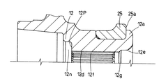
図5ないし図8を参照して本発明の参考形態に係る車両用ハブユニットについて説明する。ここで、図5は、車両用ハブユニットの縦断側面図、図6は、図5の要部の拡大図、図7は、図6に示されるハブホイールの中空軸部の拡大図、図8は、図6に示される等速ジョイントの外輪軸部の拡大図であり、図1ないし図4と対応する部分には同一の符号が付されている。
【0047】
本参考形態では、図5ないし図8で示すように、外輪軸部36の車両アウタ側軸端部における小径ねじ軸36hとスプライン嵌合領域との間の外周領域に、ナット36iの螺合に伴い軸方向の弾性伸長を許容する低剛性部としての軸方向所要長さにわたる小径部分36nを設けた。この小径部分36nは、座繰りにより形成されている。
【0048】
すなわち、ナット36iの締め付けトルクで外輪軸部36に引張応力が作用し、この引張応力により中空軸部12に軸方向圧縮力が作用する場合、前記小径部分36nの剛性が小さいので小径部分が引張応力で軸方向に弾性伸長する結果、ナット36iの締め付けトルクによる中空軸部12に対する軸方向の圧縮力は下げられる。
【0049】
これによって、ハブホイール1の中空軸部12において段壁面12gと車両アウタ側軸端の端面12hとの間の軸方向部分に対して過剰な軸方向圧縮力がかからなくなって、内輪25に対するかしめ部12aからの適正な予圧付与状態を保持することができる。
【0050】
なお、中空軸部12の車両アウタ側軸端部12cの端面に、周方向の切り欠き12nが設けられ、この切り欠き12nの内壁面12pにナット36iの端面36jが当てられるから、ナット36iを小さくしてハブユニットの軽量化を図れて好ましい。
【0051】
本発明は、上述の各実施形態に限定されるものではなく、さらに種々な変形や応用が可能である。
【0052】
(1)上述の実施形態の場合、ハブホイール1の中空軸部12の車両インナ側軸端を径方向外向きに屈曲変形してなるかしめ部12aと等速ジョイント3の外輪31における椀型筒部35との間に僅かの隙間Gが存在しているために、この隙間から泥水が浸入し、その中空軸部12内周と等速ジョイント3の外輪軸部36の外周とのスプライン間にその泥水が停滞してそこでの腐食が進行するおそれがある。
【0053】
そこで、この泥水の浸入を防ぐために、図9および図10で示す環状のシール20,21を設けてもよい。
【0054】
図9は、車両用ハブユニットの縦断側面図、図10は、各シールの構成例を示すための図9の要部における各拡大図である。
【0055】
シール20は、ゴム等の弾性体よりなり、かしめ部12aと椀型筒部35の軸方向対向面間に配設されており、凹部としての環状溝35aまたは環状の切り欠き35bに嵌入されて、隙間Gを塞いで内部への泥水の浸入を防止している。
【0056】
シール21は、ゴム等の弾性体よりなり、スプライン12f,36fより車両インナ側に位置する中空軸部12の内周領域と等速ジョイント3の外輪軸部36の外周領域との対向面に配設されており、凹部としての環状溝36mに嵌入されて、前記中空軸部21内周領域と、外輪軸部36の外周領域との間を密封することで、シール20と共にスプライン12f,36f部分への泥水の浸入を防止しそこでの腐食を防止している。
【0057】
シール20,21は、環状芯金にシールリップを固着した形態でもよい。
【0058】
両シール20,21は、必ずしも2つ必要となるものではなく、いずれか一方でもよい。
【0059】
(2)上述の実施形態の場合、椀型筒部35とかしめ部12aとを非接触としたが、本発明はこれに限定されるものではなく、椀型筒部35とかしめ部12aとが接触される構造のものに対しても、図1で示されるハブホイール1の中空軸部12に切り欠き12kを設けたり、あるいは、図5で示される等速ジョイント3の外輪軸部36に小径部分36nを設けることにより、上述の実施形態と同様に、内輪25に対する予圧に影響を及ぼす余分な負荷がかからないようにしてもよい。
【0060】
【発明の効果】
以上のように本発明の車両用軸受装置は、等速ジョイントの外輪軸部の車両アウタ側軸端にねじ軸部を設け、このねじ軸部に対してナットを螺合し、このナットをハブホイールの中空軸部の車両アウタ側端面に当てることでハブホイールに等速ジョイントの外輪を結合し、中空軸部の車両アウタ側軸端部寄りに、前記ナットの螺合に伴い軸方向の弾性圧縮を許容する低剛性部を設けて構成されており、ナットをその緩み防止を可能とするトルクで締め付けても低剛性部が車両インナ側方向に弾性圧縮し、ナットの締め付けトルクによる複列転がり軸受に対する予圧への影響を低減することができる。
【図面の簡単な説明】
【図1】本発明の実施形態にかかるハブユニットの縦断側面図
【図2】図1の要部の拡大図
【図3】図1のハブホイールの拡大図
【図4】図1の等速ジョイントの外輪軸部の拡大図
【図5】他の参考形態にかかるハブユニットの縦断側面図
【図6】図5の要部の拡大図
【図7】図5のハブホイールの拡大図
【図8】図5の等速ジョイントの外輪軸部の拡大図
【図9】本発明のさらに他の実施形態にかかるハブユニットの縦断側面図
【図10】図9の要部を拡大して各シールの変形を示す斜視図
【図11】従来のハブユニットの縦断側面図
【符号の説明】
1 ハブホイール
2 複列転がり軸受
3 等速ジョイント
12 ハブホイールの中空軸部
31 等速ジョイントの外輪軸部
35 等速ジョイントの外輪の椀型筒部
36 等速ジョイントの外輪の軸部[0001]
BACKGROUND OF THE INVENTION
The present invention relates to a vehicle bearing device such as a vehicle hub unit to which a disc rotor and wheels of a disc brake device are attached.
[0002]
[Prior art]
In the conventional drive wheel hub unit shown in FIG. 11, a double-
[0003]
The
[0004]
The
[0005]
[Problems to be solved by the invention]
In the case of the hub unit as described above, generally, preload is applied to the double row rolling bearing 2 by caulking the vehicle inner side end portion of the
[0006]
Normally, in order to connect the
[0007]
By the way, as shown in FIG. 11, the
[0008]
Therefore, as a result of earnest research, the applicant of the present application has come up with a structure capable of reducing the influence of the tightening torque of the
[0009]
Accordingly, an object of the present invention is to prevent a tightening of a nut from being loosened in a bearing device such as a vehicle hub unit so that the tightening does not affect a preload on a double row rolling bearing.
[0010]
[Means for Solving the Problems]
In the vehicle bearing device of the present invention, a double row rolling bearing is fitted on the outer periphery of a hollow shaft portion of a hub wheel to which a wheel is attached, and the hub wheel is connected to the drive shaft so as to be tiltable. A bearing device for a vehicle having a joint, wherein a vehicle inner side shaft end of a hollow shaft portion of a hub wheel is caulked to an outer end surface of a vehicle inner side inner ring of a double row rolling bearing, and an outer ring of a constant velocity joint is , A cylindrical tube portion serving as a trajectory of the tilt guide ball group, and an outer ring shaft portion that is inserted into the hollow shaft portion of the hub wheel and spline-fitted to the small diameter portion thereof, and the like A screw shaft portion is provided at the vehicle outer side shaft end of the outer ring shaft portion of the speed joint, and a nut is screwed to the screw shaft portion, and this nut is applied to the vehicle outer side end surface of the hollow shaft portion of the hub wheel. thing Constant velocity joint outer ring to the hub wheel and is coupled, circumferential groove cut, which is enlarged from the vehicle outer side end face of the inner peripheral surface of the hollow shaft portion at a position axially spaced apart vehicle inner side to the radially outward It is configured with a notch.
[0020]
DETAILED DESCRIPTION OF THE INVENTION
Hereinafter, details of the present invention will be described based on embodiments shown in the drawings.
[0021]
Although the present embodiment will be described with reference to a vehicle hub unit, the present invention is not limited to this and can be applied to a vehicle bearing device.
[0022]
1 to 4 show a vehicle hub unit according to an embodiment of the present invention, FIG. 1 is a longitudinal side view of the vehicle hub unit, FIG. 2 is an enlarged view of a main part of FIG. 1, and FIG. 2 is an enlarged view of the hollow shaft portion of the hub wheel shown in FIG. 2, and FIG. 4 is an enlarged view of the outer ring shaft portion of the constant velocity joint shown in FIG.
[0023]
The vehicle hub unit shown in the figure is a type used on the drive wheel side of an automobile, and includes a
[0024]
The
[0025]
The vehicle inner side shaft end of the
[0026]
The double
[0027]
The
[0028]
The
[0029]
One end of a shaft (drive shaft) 7 is spline fitted to the
[0030]
The double-
[0031]
Further,
[0032]
In such a vehicle hub unit, the rotational power of the
[0033]
Next, the
[0034]
Because of this connection, the
[0035]
Specifically, in the inner periphery of the
[0036]
On the other hand, the outer diameter of the
[0037]
Then, the outer
[0038]
For this positioning, a small-diameter
[0039]
The
[0040]
In the case of the above embodiment, the vertical
[0041]
Therefore, an extra load is not applied to the
[0042]
In this case, when the tightening torque is increased in order to prevent the
[0043]
That is, in this embodiment, the inner periphery of the
[0044]
By this
[0045]
Since the tightening torque of the
[0046]
A vehicle hub unit according to a reference embodiment of the present invention will be described with reference to FIGS. 5 is a longitudinal side view of the vehicle hub unit, FIG. 6 is an enlarged view of the main part of FIG. 5, FIG. 7 is an enlarged view of the hollow shaft portion of the hub wheel shown in FIG. FIG. 7 is an enlarged view of an outer ring shaft portion of the constant velocity joint shown in FIG. 6, and portions corresponding to those in FIGS. 1 to 4 are denoted by the same reference numerals.
[0047]
In the present embodiment, as shown in FIGS. 5 to 8, the
[0048]
That is, when a tensile stress acts on the outer
[0049]
As a result, in the
[0050]
In addition, since the
[0051]
The present invention is not limited to the above-described embodiments, and various modifications and applications can be made.
[0052]
(1) In the case of the above-described embodiment, the
[0053]
Therefore, in order to prevent this muddy water from entering,
[0054]
FIG. 9 is a longitudinal side view of the vehicle hub unit, and FIG. 10 is an enlarged view of a main part of FIG. 9 for illustrating a configuration example of each seal.
[0055]
The seal 20 is made of an elastic body such as rubber, and is disposed between the
[0056]
The
[0057]
The
[0058]
Two
[0059]
(2) In the case of the above-described embodiment, the saddle-shaped
[0060]
【The invention's effect】
As described above, in the vehicle bearing device of the present invention, the screw shaft portion is provided at the vehicle outer side shaft end of the outer ring shaft portion of the constant velocity joint, and the nut is screwed to the screw shaft portion. The outer ring of the constant velocity joint is coupled to the hub wheel by hitting the end surface of the hollow shaft of the wheel on the outer side of the vehicle. It is configured with a low-rigidity part that allows compression, and even if the nut is tightened with a torque that prevents it from loosening, the low-rigidity part elastically compresses in the vehicle inner side direction, and double row rolling due to the tightening torque of the nut The influence on the preload on the bearing can be reduced.
[Brief description of the drawings]
FIG. 1 is a longitudinal side view of a hub unit according to an embodiment of the present invention. FIG. 2 is an enlarged view of a main part of FIG. 1. FIG. 3 is an enlarged view of a hub wheel of FIG. Enlarged view of the outer ring shaft of the joint [Fig. 5] Vertical side view of the hub unit according to another reference embodiment [Fig. 6] Enlarged view of the main part of Fig. 5 [Fig. 7] Enlarged view of the hub wheel of Fig. 5 8 is an enlarged view of the outer ring shaft portion of the constant velocity joint of FIG. 5. FIG. 9 is a vertical side view of a hub unit according to still another embodiment of the present invention. FIG. 11 is a perspective view showing a modification of the conventional hub unit.
DESCRIPTION OF
Claims (1)
ハブホイールの中空軸部における車両インナ側軸端が複列転がり軸受の車両インナ側内輪の外端面にかしめつけられており、
等速ジョイントの外輪が、傾動案内用のボール群の軌道となる椀型の筒部とこれの小径部分にハブホイールの中空軸部に挿入されてスプライン嵌合する外輪軸部とを有する構成とされており、
前記等速ジョイントの外輪軸部の車両アウタ側軸端にねじ軸部が設けられ、このねじ軸部に対してナットが螺合され、このナットがハブホイールの中空軸部の車両アウタ側端面に当てられることでハブホイールに等速ジョイントの外輪が結合されており、
中空軸部の内周面の車両アウタ側端面から軸方向車両インナ側に離れた位置に径方向外方へ拡径された周溝状切欠きを設けた、ことを特徴とする車両用軸受装置。A vehicle bearing device including a double-row rolling bearing fitted on the outer periphery of a hollow shaft portion of a hub wheel to which a wheel is attached, and a constant velocity joint that tiltably connects the hub wheel to a drive shaft. There,
The vehicle inner side shaft end of the hollow shaft portion of the hub wheel is caulked to the outer end surface of the vehicle inner side inner ring of the double row rolling bearing,
The outer ring of the constant velocity joint has a saddle-shaped cylindrical part that serves as a trajectory of a tilting ball group, and an outer ring shaft part that is inserted into the hollow shaft part of the hub wheel at a small diameter part thereof and is spline-fitted. Has been
A screw shaft portion is provided at the vehicle outer side shaft end of the outer ring shaft portion of the constant velocity joint, and a nut is screwed to the screw shaft portion, and this nut is fitted to the vehicle outer side end surface of the hollow shaft portion of the hub wheel. The outer ring of the constant velocity joint is connected to the hub wheel by being hit,
A vehicular bearing device, characterized in that a circumferential groove-shaped notch that is radially outwardly expanded is provided at a position away from the vehicle outer side end surface of the inner peripheral surface of the hollow shaft portion toward the axial vehicle inner side. .
Priority Applications (1)
| Application Number | Priority Date | Filing Date | Title |
|---|---|---|---|
| JP2000262547A JP3822041B2 (en) | 2000-08-31 | 2000-08-31 | Vehicle bearing device |
Applications Claiming Priority (1)
| Application Number | Priority Date | Filing Date | Title |
|---|---|---|---|
| JP2000262547A JP3822041B2 (en) | 2000-08-31 | 2000-08-31 | Vehicle bearing device |
Publications (2)
| Publication Number | Publication Date |
|---|---|
| JP2002070881A JP2002070881A (en) | 2002-03-08 |
| JP3822041B2 true JP3822041B2 (en) | 2006-09-13 |
Family
ID=18750212
Family Applications (1)
| Application Number | Title | Priority Date | Filing Date |
|---|---|---|---|
| JP2000262547A Expired - Fee Related JP3822041B2 (en) | 2000-08-31 | 2000-08-31 | Vehicle bearing device |
Country Status (1)
| Country | Link |
|---|---|
| JP (1) | JP3822041B2 (en) |
Families Citing this family (5)
| Publication number | Priority date | Publication date | Assignee | Title |
|---|---|---|---|---|
| WO2008007474A1 (en) | 2006-07-11 | 2008-01-17 | Ntn Corporation | Bearing device for wheel |
| KR100925751B1 (en) * | 2007-11-16 | 2009-11-11 | 주식회사 일진글로벌 | Wheel bearing hub |
| JP5393997B2 (en) * | 2008-04-22 | 2014-01-22 | Ntn株式会社 | Wheel bearing device |
| JP5217861B2 (en) * | 2008-10-01 | 2013-06-19 | 株式会社ジェイテクト | Connecting structure and steering device |
| EP4097367B1 (en) | 2020-01-27 | 2023-12-20 | Volvo Truck Corporation | Rotational lock in inner ring of outboard bearing to avoid lock washer |
Family Cites Families (9)
| Publication number | Priority date | Publication date | Assignee | Title |
|---|---|---|---|---|
| US4371214A (en) * | 1980-11-17 | 1983-02-01 | Motor Wheel Corporation | Bearing hub and carrier assembly for a driven steering wheel unit |
| DE3636243A1 (en) * | 1986-10-24 | 1988-05-11 | Loehr & Bromkamp Gmbh | WHEEL BEARING (NY) SMOOTH JOINT UNIT |
| JPH022527U (en) * | 1988-06-17 | 1990-01-09 | ||
| JPH05319008A (en) * | 1992-05-15 | 1993-12-03 | Nippon Seiko Kk | Bearing unit with wheel balance adjusting function |
| JPH0996317A (en) * | 1995-09-29 | 1997-04-08 | Ntn Corp | Outer ring for constant velocity joint |
| DE19543436C2 (en) * | 1995-11-22 | 2000-10-12 | Fag Automobiltechnik Ag | Wheel bearings |
| JP3533883B2 (en) * | 1997-06-16 | 2004-05-31 | 日本精工株式会社 | Hub unit for wheel support |
| JP3982093B2 (en) * | 1998-02-16 | 2007-09-26 | 日本精工株式会社 | Wheel drive axle unit |
| JP2000062405A (en) * | 1998-08-25 | 2000-02-29 | Nippon Seiko Kk | Axle device for automobile |
-
2000
- 2000-08-31 JP JP2000262547A patent/JP3822041B2/en not_active Expired - Fee Related
Also Published As
| Publication number | Publication date |
|---|---|
| JP2002070881A (en) | 2002-03-08 |
Similar Documents
| Publication | Publication Date | Title |
|---|---|---|
| EP2127902B1 (en) | Bearing device for driving wheel, and its assembling method | |
| JP4044388B2 (en) | Drive wheel bearing device | |
| JP2003097588A (en) | Hub unit for automobile driving wheel | |
| JP3869202B2 (en) | Hub unit for vehicles | |
| JP4649713B2 (en) | Axle bearing device | |
| JP3869197B2 (en) | Vehicle bearing device | |
| JP4338095B2 (en) | Drive wheel bearing unit | |
| JP3905398B2 (en) | Drive wheel bearing device | |
| JP6381238B2 (en) | Assembly of hub of driving wheel and saddle-shaped body of power transmission joint | |
| JP3822041B2 (en) | Vehicle bearing device | |
| EP1621364A1 (en) | Bearing apparatus for a driving wheel of vehicle | |
| JPH115404A (en) | Wheel supporting hub unit | |
| US6588935B1 (en) | Wheel bearing assembly | |
| JP2004353724A (en) | Bearing device for driving wheel | |
| JP2023037318A (en) | Wheel bearing device | |
| JP4042528B2 (en) | Rolling bearing device | |
| JP2002187404A (en) | Wheel bearing device | |
| US11420470B2 (en) | Wheel bearing | |
| JP2007076465A (en) | Bearing device for driving wheel | |
| JP2005319889A (en) | Bearing device for driving wheel | |
| JP2003112502A (en) | Bearing device for driving wheel | |
| JP6109786B2 (en) | Wheel bearing device and method for manufacturing wheel bearing device | |
| JP2008221859A (en) | Wheel supporting device | |
| JP4481966B2 (en) | Wheel bearing device for driving wheel | |
| JP2003089301A (en) | Bearing device for driving wheel |
Legal Events
| Date | Code | Title | Description |
|---|---|---|---|
| A131 | Notification of reasons for refusal |
Free format text: JAPANESE INTERMEDIATE CODE: A131 Effective date: 20060131 |
|
| A711 | Notification of change in applicant |
Free format text: JAPANESE INTERMEDIATE CODE: A712 Effective date: 20060228 |
|
| A521 | Written amendment |
Free format text: JAPANESE INTERMEDIATE CODE: A523 Effective date: 20060403 |
|
| TRDD | Decision of grant or rejection written | ||
| A01 | Written decision to grant a patent or to grant a registration (utility model) |
Free format text: JAPANESE INTERMEDIATE CODE: A01 Effective date: 20060620 |
|
| A61 | First payment of annual fees (during grant procedure) |
Free format text: JAPANESE INTERMEDIATE CODE: A61 Effective date: 20060621 |
|
| R150 | Certificate of patent or registration of utility model |
Free format text: JAPANESE INTERMEDIATE CODE: R150 |
|
| FPAY | Renewal fee payment (event date is renewal date of database) |
Free format text: PAYMENT UNTIL: 20100630 Year of fee payment: 4 |
|
| FPAY | Renewal fee payment (event date is renewal date of database) |
Free format text: PAYMENT UNTIL: 20100630 Year of fee payment: 4 |
|
| FPAY | Renewal fee payment (event date is renewal date of database) |
Free format text: PAYMENT UNTIL: 20110630 Year of fee payment: 5 |
|
| FPAY | Renewal fee payment (event date is renewal date of database) |
Free format text: PAYMENT UNTIL: 20120630 Year of fee payment: 6 |
|
| FPAY | Renewal fee payment (event date is renewal date of database) |
Free format text: PAYMENT UNTIL: 20120630 Year of fee payment: 6 |
|
| FPAY | Renewal fee payment (event date is renewal date of database) |
Free format text: PAYMENT UNTIL: 20130630 Year of fee payment: 7 |
|
| LAPS | Cancellation because of no payment of annual fees |