JP3820699B2 - Pulse wave detector - Google Patents
Pulse wave detector Download PDFInfo
- Publication number
- JP3820699B2 JP3820699B2 JP23499497A JP23499497A JP3820699B2 JP 3820699 B2 JP3820699 B2 JP 3820699B2 JP 23499497 A JP23499497 A JP 23499497A JP 23499497 A JP23499497 A JP 23499497A JP 3820699 B2 JP3820699 B2 JP 3820699B2
- Authority
- JP
- Japan
- Prior art keywords
- pulse wave
- waveform
- detection
- polarity
- positioning sensor
- Prior art date
- Legal status (The legal status is an assumption and is not a legal conclusion. Google has not performed a legal analysis and makes no representation as to the accuracy of the status listed.)
- Expired - Fee Related
Links
Images


Landscapes
- Measuring Pulse, Heart Rate, Blood Pressure Or Blood Flow (AREA)
Description
【0001】
【発明の属する技術分野】
本発明は、脈波を検出する脈波検出装置に関し、特に操作者の熟練度などによらず安定な脈波の検出ができる脈波検出装置に関する。
【0002】
【従来の技術】
脈波検出装置の一つとして、橈骨動脈波を検出するものがある。この種の装置においては、橈骨動脈近傍の表皮の圧力の変化を圧力センサを用いて検出し、これにより脈波を測定する。この場合、橈骨動脈上の表皮に置いたセンサに加わる圧力の変化を検出しているので、安定した脈波検出を行うためには、30mmHgから80mmHgの押圧力を加える必要があり、被験者にとって圧迫感が強いという問題があった。
【0003】
例えば、米国特許NO.4951679に示される発明においては、橈骨動脈の近傍に配置させた圧力センサを腕に対して押圧し、さらに、この押圧力を順次変化させて、検出信号の振幅が最大になる押圧力を検出する。そして、その押圧力において、脈波の検出を行っている。この場合、最適な押圧力を設定することができ、必要以上の圧力がかかることを防止することはできるが、いずれにしても、腕に所定の圧力をかけることには変わりなく、圧迫感が強いという問題は解消しない。
【0004】
これに対して、強い押圧力を加える必要のない脈波検出装置として、超音波を用いるものや、光(赤外線、レーザ光など)を用いるものがある。超音波の反射波を用いる脈波検出装置にあっては、超音波を出射するプローブを被検者の腕の外側方向より当て、動脈血管などで反射した超音波をそのプローブで受信して脈波の測定を行う。
【0005】
一方、光を用いて脈波を検出する脈波検出装置においては、例えば、発光ダイオードから体内に向けて光を送出し、その反射光(皮下組織などによる反射光)の光量を検出する。この場合、発光ダイオードから放射された光の一部は、血管内のヘモグロビンに吸収されるため、その反射光量は血管内の血液容量に関係したものとなり、脈波として検出される。
【0006】
【発明が解決しようとする課題】
ところで、超音波を用いた従来の脈波検出装置では、超音波を送波および受波するプローブと血流のなす角度に応じて反射波の検出値が変化する。そして、プローブの操作においては、血流に対し一定角度を維持するのが難しく、安定した脈波の測定が困難であった。例えば、プローブを被験者の腕の掌側に当てた場合は、そのプローブの位置が動脈血管に対して数ミリずれただけで、脈波の検出が困難となってしまう。また、そのプローブを被験者の腕の背側に当てた場合は、脈波の検出に必要なSN比を確保することができない。
【0007】
また、レーザや発光ダイオードを用いる装置においても、照射光が動脈に照射されなければ、脈波波形の検出に必要なSN比を確保することができなかったり、あるいは、安定した脈波波形を検出することができない。
【0008】
本発明は、上述した事情に鑑みてなされたものであり、操作者に圧迫感を強いることなく、かつ、操作者の熟練度などの影響を受けず正確で安定した脈波を検出することができる脈波検出装置を提供することを目的としている。
【0010】
【課題を解決するための手段】
上記課題を解決するため、請求項1に記載の発明にあっては、生体の検出部位から脈波波形を検出する脈波検出手段と、前記脈波検出手段の近傍に取り付けられ、前記検出部位に光を照射する発光部とその反射光を受光する受光部とからなる位置決めセンサと、前記位置決めセンサおよび前記脈波検出手段と、前記検出部位との相対位置関係を変更する位置変更手段と、前記位置決めセンサから出力される脈波波形の振幅極性を検出する極性検出手段と、前記極性検出手段の検出結果を告知する告知手段とを備えることを特徴とする。
【0011】
また、請求項2に記載の発明にあっては、生体の検出部位から脈波波形を検出する脈波検出手段と、前記脈波検出手段の近傍に取り付けられ、前記検出部位に光を照射する発光部とその反射光を受光する受光部とからなる位置決めセンサと、前記位置決めセンサから出力される脈波波形の振幅極性を検出する極性検出手段と、前記極性検出手段によって検出される振幅極性が反転するように、前記位置決めセンサおよび前記脈波検出手段と前記検出部位との相対位置関係を変更する位置変更手段とを備えることを特徴する。
【0012】
また、請求項3に記載の発明にあっては、前記位置決めセンサによって検出される脈波波形から体動を除去して体動除去脈波波形を生成する体動除去手段を備え、前記極性検出手段は、前記体動除去脈波波形に基づいて極性を検出することを特徴とする。
【0013】
また、請求項4に記載の発明にあっては、生体の検出部位から脈波波形を検出する脈波検出手段と、前記脈波検出手段の近傍に取り付けられ、前記検出部位に光を照射する発光部とその反射光を受光する受光部とからなる位置決めセンサと、前記位置決めセンサと前記検出部位との相対位置関係を変更する位置変更手段と、前記位置決めセンサから出力される脈波波形の振幅極性を検出する極性検出手段と、前記位置決めセンサから出力される脈波波形の振幅を検出する振幅検出手段と、前記極性検出手段の検出結果と前記振幅検出手段の検出結果を告知する告知手段とを備えることを特徴とする。
【0014】
また、請求項5に記載の発明にあっては、生体の検出部位から脈波波形を検出する脈波検出手段と、前記脈波検出手段の近傍に取り付けられ、前記検出部位に光を照射する発光部とその反射光を受光する受光部とからなる位置決めセンサと、前記位置決めセンサおよび前記脈波検出手段と、前記検出部位との相対位置関係を変更する位置変更手段と、前記位置決めセンサから出力される脈波波形の振幅極性を検出する極性検出手段と、前記位置決めセンサから出力される脈波波形の振幅を検出する振幅検出手段と、前記極性検出手段によって検出される振幅極性が反転し、かつ、前記振幅検出手段によって検出される振幅が最大となるように、前記位置決めセンサおよび前記脈波検出手段と、前記検出部位との相対位置関係を変更する位置変更手段とを備えることを特徴とする。
【0015】
また、請求項6に記載の発明にあっては、前記位置決めセンサからの脈波波形から体動を除去して体動除去脈波波形を生成する体動除去手段を備え、前記極性検出手段は前記体動除去脈波波形に基づいて極性を検出するとともに、前記振幅検出手段は前記体動除去脈波波形に基づいて振幅を検出することを特徴とする。
【0016】
また、請求項7に記載の発明にあっては、前記体動除去手段は、前記生体の体動を検出する体動検出部と、前記体動検出部によって検出された体動波形の周波数解析を行う第1の周波数解析部と、前記位置決めセンサからの脈波波形の周波数解析を行う第2の周波数解析部と、前記第1の周波数解析部によって解析された周波数解析結果と、前記第2の周波数解析部によって解析された周波数解析結果とを比較して、前記体動除去脈波波形を生成する体動除去部とを備えたことを特徴とする。
【0017】
また、請求項8に記載の発明にあっては、前記第1の周波数解析部と前記第2の周波数解析部は、FFTを用いて周波数解析を行うことを特徴とする。
また、請求項9に記載の発明にあっては、前記位置変更手段は、少なくともFFTが行える最小単位時間以上の停止時間をもって移動することを特徴とする。
【0018】
また、請求項10に記載の発明にあっては、前記第1の周波数解析部と前記第2の周波数解析部は、ウエーブレット変換を用いて周波数解析を行うことを特徴とする。
また、請求項11に記載の発明にあっては、前記体動除去手段は、前記位置決めセンサからの脈波波形の周波数解析を行う周波数解析部と、前記周波数解析部によって解析された周波数解析結果のうち低域成分を除去した周波数成分に基づいて、前記体動除去脈波波形を生成する体動分離部とを備えたことを特徴とする。
【0019】
また、請求項12に記載の発明にあっては、前記周波数解析部は、FFTまたはウエーブレット変換を用いて周波数解析を行うことを特徴とする。
また、請求項13に記載の発明にあっては、前記脈波検出手段は、圧力センサであることを特徴とする。
また、請求項14に記載の発明にあっては、前記脈波検出手段は、光学式センサであることを特徴とする。
【0020】
また、請求項15に記載の発明にあっては、前記脈波検出手段と前記位置決めセンサとを兼用したことを特徴とする。
また、請求項16に記載の発明にあっては、前記脈波検出手段と前記位置決めセンサとの検出波長を、300nmから600nmの波長領域中に設定したことを特徴とする。
【0021】
【発明の実施の形態】
A.原理
まず、本発明に係わる橈骨動脈の位置検出方法について説明する。図1は、橈骨動脈の立体模型図である。血液は内皮100の中を流れる。内皮100は内膜101に覆われており、その外側には内弾性板102が形成されている。内弾性板102と外弾性板104の間には、内膜103が形成されている。内膜103は密に並んだ平滑筋で構成されている。外弾性板104の外側には外膜105が形成されており、外膜105の内部に細動脈ARが形成されている。橈骨動脈が収縮すると、内弾性板102,外弾性板104は強く波うち、それが拡張するとまっすぐ伸びる。こうした脈動によって橈骨動脈は血液を組織に供給するが、橈骨動脈自体にも血液を供給する必要がある。この役割を担うのが、細動脈ARである。
また、図2は、橈骨動脈、細動脈および毛細血管の関係を模式的に示す断面図である。この図において、RAは、内皮100と内膜101からなる橈骨動脈の内壁、ARは細動脈、CA,CA’は毛細血管、Sは皮膚である。図に示すように、橈骨動脈の内壁RAの外側には細動脈ARが形成されており、また、皮膚Sの内部には多数の毛細血管CA,CA’が形成されている。この例では、橈骨動脈の内壁RAと皮膚Sの間にある毛細血管に符号CA’を、橈骨動脈の内壁RAから離れた位置にある毛細血管に符号CAをふしてある。
毛細血管CA,CA’は網目状になっており、橈骨動脈によって運ばれた血液を組織の隅々にまで供給している。このため、橈骨動脈から検出される脈波波形と毛細血管CAから検出される脈波波形は、多少の時間遅れがあるものの、その振幅極性は一致している。
【0022】
ところで、橈骨動脈には、心臓の収縮拡張によって送り出される血液流が流れるので、図3に示すような脈動が末梢部に向けて8〜16m/sで進行していく。ここで、位置X1のように橈骨動脈の内壁RAが脈動によって拡張すると、その近傍にある細動脈ARと毛細血管CA’は橈骨動脈の内壁RAに圧迫されて虚血状態となる。一方、位置X2のように橈骨動脈の内壁RAが拡張していない状態にあっては、細動脈ARと毛細血管CA’は橈骨動脈の内壁RAに圧迫されないので、通常の血液流が流れる。
【0023】
このため、橈骨動脈の脈波波形と細動脈ARおよび毛細血管CA’の脈波波形は、その振幅極性が反転したものとなる。一方、上述したように橈骨動脈の脈波波形と毛細血管CAの脈波波形では、振幅極性が一致したものとなる。したがって、毛細血管CAの脈波波形と細動脈ARの脈波波形は、その振幅極性が反転したものとなる。図4(a)は毛細血管CAの脈波波形を、図4(b)は細動脈ARの脈波波形を各々示したものである。
【0024】
手腕の周りの皮膚Sの上から、ごく浅い内部の脈波波形を計測すると、図2に示すように毛細血管CAの脈波波形が計測される領域W1,W3と、細動脈ARおよび毛細血管CA’の脈波波形が計測される領域W2がある。ここで、位置Xsから位置Xeに向けて(周方向に)脈波波形を計測していくと、領域W2において脈波波形の振幅極性が反転することとなる。したがって、脈波波形の振幅極性が反転する位置を検知することによって、橈骨動脈の位置を特定することができる。
【0025】
本発明者らは、以上説明したように医学的な見地から毛細血管CA,CA’、橈骨動脈の内壁RA、および細動脈ARを考察した結果に着目して、橈骨動脈の位置を簡易に特定する脈波検出法を開発した。この脈波検出法の要点は、脈波検出手段を用いて生体の検出部位から脈波波形を検出する際に、脈波検出手段の近傍に取り付けられ、検出部位に光を照射する発光部とその反射光を受光する受光部とからなる位置決めセンサを設け、位置決めセンサから出力される脈波波形に基づいて、脈波検出手段と検出部位との相対位置関係を変更するものである。
【0026】
B.機能構成
次に、本実施形態に係わる脈波検出装置の機能を説明する。図5は本実施形態に係わる脈波検出装置の機能ブロック図である。図において、f1は脈波検出手段であって、生体の検出部位から脈波波形を検出する。例えば、光学式脈波センサや圧力センサ等が該当する。また、f2は振幅検出手段であって、脈波検出手段によって検出された脈波波形の振幅値を検出する。
【0027】
f3は位置決めセンサであって、脈波検出手段f1と一体に取り付けられ、検出部位に光を照射する発光部とその反射光を受光する受光部とから構成されている。この位置決めセンサf3によって、毛細血管CAと細動脈RAおよび毛細血管CA’の脈波波形が検出される。
【0028】
また、f4は極性検出手段であって、位置決めセンサf2から出力される脈波波形の振幅極性を検出する。これにより、脈波波形の振幅極性が反転した位置を特定することができる。また、f5は位置変更手段であって、位置決めセンサf2および脈波検出手段f1と検出部位との相対位置関係を変更する。変更の態様としては、被験者が操作するものと、極性検出手段f3の検出結果に基づいて自動的に位置制御を行うものとがある。自動変更を行う場合には、図中点線で示すように、極性変更手段f4によって検出された振幅極性や振幅検出手段f2によって検出された振幅値に基づいて位置変更手段f5は位置変更を行う。
【0029】
また、f6は告知手段であって、脈波検出手段f1によって検出された脈波波形、脈波波形に基づいて求められた生体の状態を示す生態情報、極性検出手段f3および振幅検出手段f2検出結果等を告知する。位置変更手段f4が手動によるもので構成される場合には、被験者は告知手段f3によって、脈波検出手段f1が適切な位置にあるか否かを知ることができる。
【0030】
C.第1実施形態
以下、図面を参照しつつ、本発明の第1実施形態に係わる脈波検出装置を説明する。
1.第1実施形態の構成
1−1:電気的構成
図6は、第1実施形態に係わる脈波検出装置の電気的構成を示すブロック図である。図において、1は位置決めセンサであって、毛細血管CA,CA’および細動脈ARの脈波波形MHを検出する。位置決めセンサ1は、図7に示すようにLED32(発光部)、フォトトランジスタ33(受光部)などから構成される。この図において、スイッチSWがon状態となり、電源電圧が印加されると、LED32から光が照射され、血管や組織によって反射された後に、フォトトランジスタ33によって受光され、脈波波形MHが検出される。ここで、LEDの発光波長は、血液中のヘモグロビンの吸収波長ピーク付近に選ばれる。このため、受光レベルは血流量に応じて変化する。したがって、受光レベルを検出することによって、脈波波形を検出できる。
【0031】
また、LED32としては、InGaN系(インジウム−ガリウム−窒素系)の青色LEDが好適である。青色LEDの発光スペクトルは、例えば450nmに発光ピークを有し、その発光波長域は、350nmから600nmまでの範囲にある。この場合には、かかる発光特性を有するLEDに対応させてフォトトランジスタ33として、GaAsP系(ガリウム−砒素−リン系)のフォトトランジスタを用いればよい。このフォトトランジスタ33の受光波長領域は、例えば、主要感度領域が300nmから600nmまでの範囲にあって、300nm以下にも感度領域がある。このような青色LEDとフォトトランジスタ33とを組み合わせると、その重なり領域である300nmから600nmまでの波長領域において、脈波が検出される。この場合には、以下の利点がある。
【0032】
まず、細動脈ARは橈骨動脈の血管壁を外側から取り巻くように形成されており、また、橈骨動脈の内壁RAと皮膚Sの間に毛細血管CA’が形成されている。このため、仮に細動脈ARおよび毛細血管CA’の脈波波形MHを検出する目的で照射した光が橈骨動脈の内壁RAの内部まで届くと、その血液流を検出してしまう。橈骨動脈の脈波波形と毛細血管CAの脈波波形の振幅極性は、上述したように同一であるから、照射光が橈骨動脈RAの内部まで届くと、腕の周方向に位置決めセンサ1を移動させても、橈骨動脈の位置で脈波波形MHの振幅極性の反転せず、橈骨動脈の位置を特定することができない。しかし、波長領域が700nm以下の照射光は、生体の組織を透過しにくい傾向があり、皮膚表面から2mm〜3mm程度までしか届かない。また、橈骨動脈は、皮膚の表面から3mm以上深い所にあるのが通常である。したがって、検出光の範囲(照射光と受光感度が重複する範囲)を300nmから600nmまでの波長領域に設定すると、橈骨動脈の血液流の影響を受けることなく毛細血管CAと細動脈ARおよび毛細血管CA’の脈波波形MHを検出することができる。
【0033】
また同様に、外光に含まれる光のうち、波長領域が700nm以下の光は、生体の組織を透過しにくい傾向があるため、外光が遮光部分(後述するバンド)で覆われていない皮膚に照射されても、生体の組織を介してフォトトランジスタ33まで到達せず、検出に影響を与えない波長領域の光のみがフォトトランジスタ33に達する。一方、300nmより低波長領域の光は、皮膚表面でほとんど吸収されるので、受光波長領域を700nm以下としても、実質的な受光波長領域は、300nm〜700nmとなる。したがって、検出部位を大掛かりに覆わなくとも、外光の影響を抑圧することができる。
【0034】
また、血液中のヘモグロビンは、波長が300nmから700nmまでの光に対する吸光係数が大きく、波長が880nmの光に対する吸光係数に比して数倍〜約100倍以上大きい。したがって、この例のように、ヘモグロビンの吸光特性に合わせて、吸光特性が大きい波長領域(300nmから700nm)の光を検出光として用いると、その検出値は、血量変化に応じて感度よく変化するので、血量変化に基づく脈波波形MHのS/N比を高めることができる。
【0035】
次に、2は手動位置変更機構であって、位置決めセンサ1の橈骨動脈に対する相対的な位置関係を手動によって変更できるようになっている。この例における手動位置変更機構2は機械的な構成であるので、この点については後述する。
【0036】
次に、3は脈波波形MHの振幅極性を検出して極性検出信号KSを出力する極性検出部である。図8は、極性検出部2の回路図である。図に示すように極性検出部3は、+V,−Vの電源電圧が供給されるオペアンプ30、抵抗31,32から構成されている。オペアンプ30の正入力には、その出力が抵抗31,32を介して正帰還されており、これによりヒシテリシスコンパレータが構成される。ヒシテリシスコンパレータは2つの閾値L1,L2(L1>L2)を持ち、その出力信号は入力信号がL1を越えるとハイレベルとなり、L2を下回るとローレベルとなる。この例において、抵抗31,32の値をR1,R2とすれば、L1,L2は以下の式で与えられる。
L1=+V・R2/(R1+R2)、L2=−V・R2/(R1+R2)
したがって、脈波波形MHが閾値L1を上回れば極性検出信号KSはハイレベルとなり、脈波波形MHが閾値L2を上回れば極性検出信号KSはローレベルとなる。
【0037】
次に、4は表示部であって、液晶表示装置によって構成される。そこには、極性検出部2で検出された振幅極性、また、橈骨動脈の脈波波形Mの振幅値、脈拍数等の生態情報が表示される。振幅極性は、例えば、「+」「−」といった記号で表示される。これにより、手動位置変更機構2を被験者が操作すると、位置決めセンサ1で検出された脈波波形MHの振幅極性が表示部4に表示されるので、被験者は、振幅極性が反転した位置、すなわち、橈骨動脈の位置を知ることができる。
【0038】
次に、5は脈波検出部であって、橈骨動脈の内壁RAの脈動を脈波波形Mとして検出する。この例における脈波検出部5は、圧力センサによって構成されている。圧力センサは、脈動を圧力として検出するものであるから、脈波測定時に、脈波検出部5を皮膚の上から橈骨動脈RAに押しつけることができるようになっている。また、8は生体情報生成部であって脈波波形Mに基づいて、その振幅値、脈拍数等の生体情報を生成する。
【0039】
以上の構成によって、被験者が手動位置変更機構2を操作すると、位置決めセンサ1によって検出された脈波波形MHの振幅極性が極性検出部3によって検出され、これが表示部4に表示される。橈骨動脈の内壁RAの周辺にある細動脈ARおよび毛細血管CA’の脈波波形は、毛細血管CAの脈波波形MHとその振幅極性が反転したものとなるので、被験者は、表示部4に表示される振幅極性が反転した位置を橈骨動脈の位置として認識することができる。これにより、脈波検出部5を橈骨動脈の上部に位置決めすることができる。また、より正確に位置決めを行う場合には、表示部4に表示される脈波波形Mの振幅値が最大になるように位置決めを行うことも可能である。
【0040】
1−2:機械的構成
次に、図9は、本実施形態に係わる脈波検出装置の外観を示す斜視図である。この図に示すように、本実施形態は腕時計の形態をとっている。ここで、図9に示す18は本体であり、前述した極性検出部3と表示部4を収納している。なお、本体18には、図示せぬ時計ICが設けられており、表示部4は図9に示すように、時計ICが出力する時刻情報を表示する。また、11は各種操作を行うための操作ボタンであり、例えば、脈波を測定する測定モードと時刻を表示する時計モードの切り替えなどを行う。
【0041】
また、本体18には、一対のバンド13a、13bが取り付けられており、図10に示すように、これらを腕に巻き付け、所定の止め金具12で止めることにより、腕に装着される。14は、バンド13a,13bに沿って移動可能な矩形断面の筒状の摺動体であり、この摺動体14内に位置決めセンサ1と脈波検出部5が設けられている。したがって、摺動体14を移動させると、位置決めセンサ1と脈波検出部5とが一体となって移動する。また、脈波検出部5は半球状の形状をしており、位置決め時には摺動体14の内部に陥没している。そして、脈波検出部5は、ボタン14aを引っ張ると突出し、押し込むと陥没するようになっている。したがって、位置決め時には、ボタン14aを押し込んだ状態で摺動部14の位置を調整し、橈骨動脈の脈波波形を測定する際にボタン14aを引っ張って脈波検出部5を突出させる。これにより、位置決めを行う際に摺動部14を円滑に移動させることができるので、被験者が圧迫感を受けることにならない。
【0042】
また、位置決めセンサ1および脈波検出部5と本体18との間には、図示せぬケーブルが設けられており、これにより、検出された脈波波形MH,Mが伝達されるようになっている。
【0043】
2.第1実施形態の動作
次に、第1実施形態の動作について説明する。まず、バンド13a,13bを腕に巻き、止め金具12によって固定する。そして、操作ボタン11を操作することによって、位置決めモードに設定する。この結果、位置決めセンサ1の発光部(LED32)から光が被験者の腕に照射され、その反射光が受光部(フォトトランジスタ33)で受光される。血管を流れる血液は、上述したように光を吸収する吸光特性を持っているから、受光部が受光する反射光の光量は、毛細血管CA,CA’や細動脈ARを流れる血液によって減衰する。その減衰量は、その血管における照射光が貫く部位の血液容量の関数となり、すなわち、毛細血管CA,CA’や細動脈ARを流れる血液の脈波に対応したものとなる。
【0044】
ここで、摺動体14が図2に示す位置Xsにあり、これを位置Xeまで移動させるものとする。この場合、位置決めセンサ1によって検出される脈波波形MHは、摺動体14の移動速度にもよるが、十分低速で移動させたとすると、図11(a)に示す脈波波形MHとなる。なお、同図(a)に示すL1,L2は、極性検出部3に用いられるヒシテリシスコンパレータの閾値である。
【0045】
ヒシテリシスコンパレータの出力は、脈波波形MHの振幅が閾値L1を越えるとハイレベルとなり、閾値L2を下回るとローレベルになるから、振幅極性検出信号KSは同図(b)に図示したものとなる。ここで、振幅極性検出信号KSがハイレベルの期間T1,T3は図2に示す領域W1,W3に対応し、一方、ローレベル期間T2は図2に示す領域W2に対応する。
【0046】
この場合、期間T1,T3においては表示部4に「+」が、期間T2においては表示部4に「−」が表示されるが、摺動体14の移動距離に対して橈骨動脈の太さは小さいから、期間T2はごく短い期間となる。したがって、被験者は表示部4に表示される振幅極性を見ながら摺動体14を移動させることによって、橈骨動脈RAの位置を知ることができる。
【0047】
このようにして、橈骨動脈の上に摺動体14を移動させた後、図9に示すボタン14aを引っ張ると、脈波検出部5が腕の側に突出する。ここで、脈波検出部5と位置決めセンサ1は摺動体14の回動方向と垂直方向に取り付けられているから、位置決めセンサ1と脈波検出部5は橈骨動脈の上に位置する。したがって、脈波検出部5は、橈骨動脈を正確に押圧することができる。
【0048】
この後、操作ボタン11を操作することによって、脈波検出モードに設定されると、表示部4には脈波検出部5によって検出された脈波波形Mの振幅値が表示される。ここで、被験者は脈波波形Mの振幅が最大となるように、摺動体14の位置を微調整することによって、より正確な脈波波形Mを検知することができる。
【0049】
3.第1実施形態の変形例
(1)告知手段の一例
前述のように、本実施形態によれば、表示によって脈波検出部5と橈骨動脈の位置関係を操作者に告知するようにしたが、これに代えて音によって告知するように構成してもよい。すなわち、極性検出部3の振幅極性検出信号KSに基づいて発音を行う発音手段VOを設けてもよい。そして、発音手段においては、例えば、振幅極性検出信号KSのレベルに応じて、音量、音高、音色、などの音の属性を変えることによって、脈波検出部5と橈骨動脈RAの位置関係を告知するように構成する。また、音の発音間隔、例えば、ピッピッピという電子音の発音間隔などを変化させることによって告知してもよい。
【0050】
(2)脈波検出部5の位置決め方法の一例
前述のように、本実施形態によれば、表示部4の表示を見ながら、脈波検出部5の位置を良好に設定することができるが、腕に装着した際の当初の位置決めにおいても、できるだけ橈骨動脈付近を貫通するようにした方が好適である。そこで、一応の目安として、バンド13aにマークを付けるとよい。すなわち、図10に示すように、バンド13aに所定の間隔で目盛り13m、13m……を付けておき、摺動体14がどの目盛りの位置のときに伝送路Lが良い位置に達したかを覚えておく。そして、バンド13a,13bを腕に装着した直後に、摺動体14の位置をその目盛り位置に調整する。このようにすれば、測定モードに移行した後の摺動体14の調整量が少なくて済み、測定が迅速に行える。
【0051】
C.第2実施形態
1.第2実施形態の構成
図12は、第2実施形態に係わる脈波検出装置の電気的構成を示すブロック図である。本実施形態は、前述の第1実施形態の構成における摺動体14(手動位置変更機構2)に代えて、自動位置変更機構10と制御部6を設けたものである。
自動位置変更機構10は、位置決めセンサ1および脈波検出部5を腕の周方向(橈骨動脈RAに対して直交する方向)に駆動するものであり、制御部6によって駆動される。制御部6は、振幅極性信号KSに基づいて、その振幅極性が反転する中央に位置決めセンサ1および脈波検出部5が位置するようにパルス駆動信号DSを生成する。
【0052】
ここで、図13は、自動位置変更機構10の外観を示す正面図(皮膚側)であり、図示のようにバンド13bが貫通している。自動位置変更機構10の内部は、リニアパルスモータの構成になっており、図示の10bはそのスライダである。このリニアパルスモータは、パルス駆動信号DSによって内部コイルの励磁条件を変更し正確に一定ピッチづつ直線的に歩進するようになっている。スライダ10bには、皮膚側に可動部10cが設けられており、この可動部10cに位置決めセンサ1と脈波検出部5が取り付けられている。可動部10cは、溝10aに沿って図面左右方向に1cm程度のストロークで移動自在である。
【0053】
2.第2実施形態の動作
以上の構成において、位置決めモードが設定されると、制御部6は、自動位置変更機構10を初期化するように駆動信号DSを出力する。具体的には、図13に示す可動部10cをみぞ10aの右端に移動させる。
【0054】
この後、制御部6は可動部10cを右から左へ一定の速度で移動させるように自動位置変更機構10を制御する。この場合、可動部10cの移動速度は、脈波波形MHの反転を検出できるように設定される。可動部10cが移動を開始すると、位置決めセンサ1からの脈波波形MHに基づいて、極性検出部3はその振幅極性を検出し、振幅極性信号KSを生成する。
【0055】
振幅極性信号KSが制御部6に供給されると、制御部6は振幅極性信号KSが反転するまで、可動部10cを左方向へ移動させるように制御する。橈骨動脈の内壁RAの血管径は、可動部10cのストローク(1cm)に対して小さく、また、バンド13bに対する自動位置変更機構10の取り付け位置は、自動位置変更機構10の中心が橈骨動脈と略一致するように設定される。このため、可動部10cの初期化時に位置決めセンサ1が橈骨動脈の上部に位置することはごく稀であり、可動部10cは初期化時に図2に示す位置Xsに位置する。したがって、初期化位置から可動部10cが移動を開始すると、まず、毛細血管CAの脈波波形MHが位置決めセンサ1によって検出される。そして、さらに可動部10cが移動すると、細動脈ARおよび毛細血管CA’の脈波波形MHが検出される。ここで、毛細血管CAの脈波波形MHと細動脈ARおよび毛細血管CA’の脈波波形MHとの振幅極性は反転するから、振幅極性信号KSが反転した時、可動部10cは橈骨動脈の左端上部に位置している。
【0056】
制御部6は振幅極性信号KSの反転を検知すると、パルス駆動信号DSのパルス数のカウントを開始し、振幅極性信号KSの振幅極性が再反転するまでカウントを行う。振幅極性信号KSが再反転するのは、位置決めセンサ1によって検出される脈波波形MHが、細動脈ARおよび毛細血管CA’から毛細血管CAに切り替わった時である。すなわち、このタイミングにおいて、可動部10cは橈骨動脈の右端上部に位置している。
【0057】
この後、制御部6は、カウントされたパルス駆動信号DSのパルス数を半分にし、このパルス数だけ可動部10cを逆方向に移動させるようにパルス駆動信号DSを生成する。これにより、可動部10cを橈骨動脈の真上に移動させることができる。
【0058】
次に、制御部6は、可動部10cに設けられた脈波検出部5を突出せるように制御信号CSを生成して自動位置変更機構10に供給する。この制御信号CSを自動位置変更機構10が検知すると、自動位置変更機構10は、脈波検出部5を皮膚側に突出させる。これにより、脈波検出部5によって橈骨動脈の脈波波形Mが検出される。
【0059】
以上の動作の結果、脈波検出部5は、脈波波形Mが最大になる位置に制御される。本実施形態においては、圧力センサによって位置決めする装置(例えば、米国特許NO.4951679)と異なり、位置決めを行う際には、脈波検出部5を表皮に押しつけていないので、可動部10cを腕の表皮に沿って移動させる力は少なくて済む。したがって、一般的なリニアパルスモータのトルクで十分にサーボ制御が可能である。また、動脈血管の径から、可動部10cの移動距離は1cm程度あれば、十分に脈波検出部5の最適位置を見つけることができる。
【0060】
3.第2実施形態の変形例
(1)第2実施形態においては、表示部4における振幅値の表示を省略してもよい。これは、装置がサーボ機構によって自動的に脈波検出部5を最適位置にするので、利用者が振幅値をモニタしなくてもよいからである。ただし、表示部4で振幅値を表示すれば、サーボ機構の動作状況を知ることができ、また、仮にサーボ機構が故障した場合には、手動によって脈波検出部5の位置を最適化することができる。
【0061】
(2)第2実施形態において、脈波検出部5で検出される脈波波形Mの振幅値を制御部6に供給し(図12中の点線を参照)、この振幅値と振幅極性信号KSに基づいてパルス駆動信号DSを生成してもよい。この場合、制御部6は振幅極性信号KSの反転を検知すると、制御信号CSを自動位置変更機構10に供給する。制御信号CSを自動位置変更機構10が検知すると、自動位置変更機構10は、脈波検出部5を皮膚側に突出させる。これにより、脈波検出部5によって橈骨動脈の脈波波形Mが検出される。この後、制御部6は、可動部10cを右に1ピッチ移動させ、脈波波形Mの振幅値が大きくなるか否かを判定する。仮に大きくなっていたら、さらに、1ピッチ右に移動させ、振幅値が大きくなるか否かを測定する。以後同様にして、右に移動させて行き、振幅値が小さくなったときは、1ピッチ左に戻って移動を終了する。以上の動作の結果、脈波検出部5は、脈波波形Mの振幅が最大になる位置に制御される。
【0062】
ところで、ランニング等の運動中にあっては、腕に巻き付けたベルトが腕の振りよってずれることがある。このような場合、脈波検出部5の位置が橈骨動脈RAの真上からずれてしまい、脈波波形MのSN比が劣化することが起こりうる。そこで、制御部6において、脈波波形Mの振幅値が過去の平均した振幅値からある値を越えて低下したこと検知し、これをトリガとして、再度、上述した振幅値に基づく脈波検出部5の位置変更を行うようにしてもよい。
【0063】
C:第3実施形態
上述した第1,第2実施形態は、位置決めセンサ1で検出された脈波波形MHの振幅極性を検出し、この検出結果に基づいて脈波検出部5の位置決めを行うものであった。ところで、運動時には毛細血管CA,CA’や細動脈ARを流れる血液流は体動の影響を受けるため、脈波波形MHに体動成分が重畳し、脈波波形MHの振幅が脈動とは無関係に大きく変動する。このような場合、位置決めセンサ1の出力に基づいて振幅極性を判定すると、体動の影響を受けて振幅極性を正確に判定できないこともある。そこで、第3実施形態にあっては、体動成分を除去した後に振幅極性を検出することにより、体動がある場合であっても正確に脈波検出部5の位置決めを行うようにしている。
【0064】
第3実施形態に係わる脈波検出装置の電気的構成を図14に示す。この脈波検出装置の構成は、位置決めセンサ1と極性検出部3との間に体動除去手段7を設けた点を除いて、上述した第2実施形態の脈波検出装置と同様である。体動除去手段7は、脈波波形MHから体動波形を除去して体動除去脈波波形MH’を生成する。体動除去手段7の具体的な構成としては、以下の構成例がある。
【0065】
1.構成例1
図15は、体動除去手段7の構成例1を示すブロック図である。図において、70は体動検出部であって、本体18(図9参照)の内部に設けられ、加速度センサ等で構成される。体動検出部70によって、生体の体動を示す体動波形THが検出される。
また、71は第1の周波数解析部であって、体動波形THに周波数解析を施して、体動解析データTKDを生成する。一方、72は第2の周波数解析部であって、脈波波形MHに周波数解析を施して、脈波解析データMKDを生成する。周波数解析の手法には、FFT(高速フーリエ変換)の他、ウエーブレット変換等がある。この例にあっては、ウエーブレット変換を一例として説明する。
【0066】
一般に、信号を時間と周波数の両面から同時に捉える時間周波数解析において、ウエーブレットは信号の部分を切り出す単位となる。ウエーブレット変換は、この単位で切り出した信号各部の大きさを表している。ウエーブレット変換を定義するために基底関数として、時間的にも周波数的にも局在化した関数ψ(x)をマザー・ウエーブレットとして導入する。ここで、関数f(x)のマザー・ウエーブレットψ(x)によるウエーブレット変換は次のように定義される。
【数1】

数1においてbは、マザー・ウエーブレットψ(x)をトランスレート(平行移動)する際に用いるパラメータであり、一方、aはスケール(伸縮)する際のパラメータである。したがって、数1においてウエーブレットψ((x−b)/a)は、マザー・ウエーブレットψ(x)をbだけ平行移動し、aだけ伸縮したものである。この場合、スケールパラメータaに対応してマザー・ウエーブレットψ(x)の幅は伸長されるので、1/aは周波数に対応するものとなる。
【0068】
ここで、第1の周波数解析部71の詳細な構成について説明する。図16は第1の周波数解析部71の詳細な構成を示すブロック図である。なお、第2の周波数解析部72も第1の周波数解析部71と同様に構成される。この第1の周波数解析部71は、上記した数1の演算処理を行う構成であって、クロックCKが供給され、クロック周期で演算処理が行われるようになっている。図示するように第1の周波数解析部71は、マザー・ウエーブレットψ(x)を記憶する基底関数記憶部W1、スケールパラメータaを変換するスケール変換部W2、バッファメモリW3、トランスレートを行う平行移動部W4および乗算部W5から構成される。なお、基底関数記憶部W1に記憶するマザー・ウエーブレットψ(x)としては、ガボールウエーブレットの他、メキシカンハット、Haarウエーブレット、Meyerウエーブレット、Shannonウエーブレット等が適用できる。
【0069】
まず、基底関数記憶部W1からマザー・ウエーブレットψ(x)が読み出されると、スケール変換部W2はスケールパラメータaの変換を行う。ここで、スケールパラメータaは周期に対応するものであるから、aが大きくなると、マザー・ウエーブレットψ(x)は時間軸上で伸長される。この場合、基底関数記憶部W1に記憶されるマザー・ウエーブレットψ(x)のデータ量は一定であるので、aが大きくなると単位時間当たりのデータ量が減少してしまう。スケール変換部W2は、これを補うように補間処理を行うとともに、aが小さくなると間引き処理を行って、関数ψ(x/a)を生成する。このデータはバッファメモリW3に一旦格納される。
【0070】
次に、平行移動部W4はバッファメモリW3からトランスレートパラメータbに応じたタイミングで関数ψ(x/a)を読み出すことにより、関数ψ(x/a)の平行移動を行い関数ψ(x−b/a)を生成する。
【0071】
次に、乗算部W5には、図示せぬA/D変換器を介して体動波形THをA/D変換して得た体動波形データTHDが供給される。乗算部W4は、変数1/a1/2、関数ψ(x−b/a)および体動波形データTHDを乗算してウエーブレット変換を行い、体動解析データTKDを生成する。この例において、体動波形データTKDは、0Hz〜0.5Hz、0.5Hz〜1.0Hz、1.0Hz〜1.5Hz、1.5Hz〜2.0Hz、2.0Hz〜2.5Hz、2.5Hz〜3.0Hz、3.0Hz〜3.5Hz、3.5Hz〜4.0Hzといった周波数領域に分割されて出力される。なお、第2の周波数解析部72も、第1の周波数解析部71と同様に構成される。
【0072】
次に、図15に示す73は体動除去部であって、脈波解析データMKDから体動解析データTKDを減算して、体動除去脈波解析データMKD’を生成し、これに逆ウエーブレット変換、D/A変換を施して体動除去脈波波形MH’を生成する。逆ウエーブレット変換は、上述したウエーブレット変換と相補的な関係にあり、そこでは以下に示す数2の演算がなされる。
【数2】
ここで、構成例1の動作を図面を参照しつつ説明する。この例では、使用者が手でコップを持ち上げた後、これを元の位置に戻した場合を想定する。この場合、図17(a)に示す脈波波形MHが脈波検出部5によって検出され、また、同時に図17(b)に示す体動波形THが体動検出部70によって検出されたものとする。
【0074】
ここで、体動波形THは、時刻T1から増加しはじめ、時刻T2で正のピークとなり、その後、次第に減少して時刻T2でレベル0を通過し、時刻T3で負のピークに達し、時刻T4でレベル0に戻っている。ところで、体動波形THは加速度センサ等によって検出されるため、時刻T3は使用者がコップを最大に持ち上げた時刻に対応し、時刻T1は持上開始時刻に対応し、また、時刻T4は持上終了時刻に対応する。したがって、時刻T1から時刻T4までの期間が体動が存在する期間となる。なお、図16(c)は仮に体動がなかったとした場合の脈波波形MH’である。また、この例において、脈波波形MHの基本波周波数は、1.3Hzとなっている。
【0075】
次に、図18〜図20を参照して、図17に示す期間Tcにおける脈波検出装置の動作を説明する。図18は期間Tcにおける脈波解析データMKDを示し、図18に期間Tcにおける体動解析データTKDを示す。この図から、体動波形THには、0.0Hz〜1.0Hzの周波数領域において比較的大きなレベルの周波数成分が存在していることが判る。
【0076】
脈波解析データMKDと体動解析データTKDが、体動除去部73に供給されると、体動除去部73は、脈波解析データMKDから体動解析データTKDを減算して、図20に示す体動除去脈波解析データMKD’を生成する。これにより、体動がある場合でもその影響をキャンセルして体動除去脈波解析データMKD’を得ることができる。この後、体動除去部73は体動除去脈波解析データMKD’に逆ウエーブレット変換を施して、図17(c)に示す体動除去脈波波形MH’を生成する。
【0077】
このように構成例1にあっては、体動検出部70で検出された体動波形THに基づいて、脈波波形MHに重畳している体動成分を除去し体動除去脈波波形MH’を生成したので、腕の振り等の体動がある場合であっても、正確に橈骨動脈の位置を検出することが可能となる。この例は、脈波検出中に脈波波形Mの振幅値が最大となるように、自動位置変更機構10をフィードバック制御する場合に好適である。
【0078】
2.構成例2
構成例1においては、体動検出部70によって体動波形THを検出し、体動波形THにウエーブレット変換を施した。そして、脈波波形MHのウエーブレット変換の結果と、体動波形THのウエーブレット変換の結果とを比較して、脈波波形MHの周波数成分に含まれている体動成分をキャンセルし体動除去脈波波形MH’を生成した。しかし、構成例1では、体動検出部70および第1の周波数解析部71が必要になるので、構成が複雑になる。構成例2は、この点に鑑みてなされたものである。
【0079】
図21は、体動除去手段7の構成例2を示すブロック図である。この例にあっては、体動除去手段7は、第2の周波数解析部72と体動分離部74から構成される。第2の周波数解析部72については構成例1と同一である。体動分離部74は、脈波解析データMKDから体動成分を分離除去して体動除去脈波波形MH’を生成する。体動分離部74は、以下に述べる体動の性質を利用している。
【0080】
体動は、腕の上下動や走行時の腕の振り等によって生じるが、日常生活においては、人体を瞬間的に動かすことはほとんどない。このため、日常生活では、体動波形THの周波数成分はそれほど高くなく、0Hz〜1Hzの範囲にあるのが通常である。この場合、脈波波形MHの基本波周波数は、1Hz〜2Hzの範囲にあることが多い。したがって、日常生活において、体動波形THの周波数成分は脈波波形MHの基本波周波数よりも低い周波数領域にある。
【0081】
一方、ジョギング等のスポーツ中にあっては、腕の振り等の影響があるため、体動波形THの周波数成分が幾分高くなるが、運動量に応じて心拍数が増加するため、脈波波形MHの基本波周波数も同時に高くなる。このため、スポーツ中においても、体動波形THの周波数成分は脈波波形MHの基本波周波数よりも低い周波数領域にあるのが通常である。
【0082】
体動分離部74は、この点に着目して体動成分を分離するものであり、脈波波形MHの基本波成分よりも低い周波数領域を無視するように構成されている。この場合には、脈波波形MHの基本波成分より高い周波数領域に体動成分が存在すると脈象の検出精度が低下する。しかしながら、上述したように体動成分は脈波波形MHの基本波成分よりも低い周波数領域にある確率が高いので、高い精度で体動を除去することが可能である。すなわち、体動分離部74は、周波数解析結果のうち低域成分を除去した周波数成分に基づいて、体動除去脈波波形MH’を生成するものである。
【0083】
図21において、波形整形部741は脈波波形MHに波形整形を施して、脈波波形MHと同期したリセットパルスを生成する。カウンタ742は図示せぬクロックパルスを計数し、前記リセットパルスによってカウント値がリセットされるようになっている。また、平均値算出回路743は、カウンタ742のカウント値の平均値を算出する。この平均値は、脈波波形MHの平均周期に対応する。したがって、平均値を参照すれば、脈波波形MHの基本波周波数を検知できる。
【0084】
次に、置換回路744は、前記平均値に基づいて、脈波波形MHの基本波周波数を含む周波数領域を特定する。例えば、前記平均値が0.71秒を示す場合には、基本波周波数は1.4Hzとなるので、特定される周波数領域は1Hz〜1.5Hzとなる。この後、置換回路744は、特定周波数領域未満の周波数領域について、脈波解析データMKDを「0」に置換して体動分離脈波データTBDを生成する。これにより、脈波波形MHの基本波周波数より低い周波数領域の成分は無視される。この場合、体動成分とともに脈波成分も「0」に置換されてしまうが、脈波波形MHの特徴的な部分は基本波周波数よりも高域の周波数領域に存在するため、「0」に置換しても最終的に得られる体動除去脈波波形MH’にほとんど影響を与えない。次に、逆変換部745は体動分離脈波データTBDに逆ウエーブレット変換を施して体動除去脈波波形MH’を生成する。
【0085】
このように構成例2にあっては、体動検出部70および第1の周波数解析部71を用いることなく、体動分離部74によって体動除去脈波波形MH’を生成したので、簡易な構成で正確に橈骨動脈の位置を検出することが可能となる。この例は、構成例1と同様に脈波検出中に脈波波形Mの振幅値が最大となるように、自動位置変更機構10をフィードバック制御する場合に好適である。
【0086】
3.第3実施形態の変形例
(1)上述した第3実施形態にあっては、体動除去手段7を用いて位置決めセンサ1からの脈波波形MHより体動を除去したが、これを脈波検出部5によって検出される脈波波形Mに適用して、体動除去脈波波形M’を生成するようにしてもよい。
【0087】
(2)上述した第3実施形態にあっては、第2実施形態と同様に自動位置変更機構10を有する脈波検出装置を一例として説明したが、第1実施形態で説明した手動位置変更機構2を有する脈波検出装置に、体動除去手段7を適用してもよいことは勿論である。
【0088】
(3)上述した第3実施形態にあって、ウエーブレット変換の出力には、各周波数領域と時間領域には一定の関係があるので、分割する周波数領域に応じて検出時間が定まる。このため、自動位置変更部10を検出時間単位毎に間欠駆動するのが好適である。また、周波数解析の手法としてFFTを用いる場合には、自動位置変更部10をFFTが行える検出時間単位毎に間欠駆動するのが好適である。
【0089】
D.変形例
本発明は上述した各実施形態に限定されるものではなく、以下に述べる各種の変形が可能である。
(1)上述した各実施形態においては、脈派を検出する生体の部位として、手首の橈骨動脈を一例として説明したが、本発明はこれに限定されるものではなく、脈派の検出部位に相当する動脈はどのようなものであってもよい。すなわち、人の動脈には、図22に示すように各種のものがあるが、上述した脈派検出装置の形態を検出部位に合わせて変形すれば、各種の動脈の位置決めを行うことができ、正確な脈波波形の検出が可能である。
【0090】
例えば、首の頚動脈から脈波波形Mを検出する場合にあっては、図23に示すように構成すればよい。この図において、30は、アーチ状の装着部であり、洋服のカラーの内側部分に装着できるようになっている。この装着部30の内側には、自動位置変更機構10が取り付けられている。自動位置変更機構10からはコードが引き出され、制御ボックス35に接続されている。制御ボックス35には、表示部4や極性検出部3が設けられている。制御ボックス35は、例えば、洋服のポケットなどに入る大きさに設定されている。上述した構成によるこの実施形態の動作は、前述した第2実施形態と同様である。
【0091】
また、自動位置変更機構10に代えて、第1実施形態のように、手動で脈波検出部5を動かすかす構成にしてもよい。また、頚動脈から脈波を検出するための装着部30としては、上述したタイプのみならず、ネックレスの輪のような形状にしても、ネクタイのループ部分の形状にしても、あるいは、首輪のような形にしてもよい。
【0092】
(2)上述した各実施形態は、脈波検出部5の一例として圧力センサを取り上げたが、本発明はこれに限定されることなく、例えば、光学式センサを使用してもよい。光学式センサとしては、位置決めセンサ1と同様の形式である反射型の他、透過型のセンサを使用することもできる。また、超音波を用いたセンサを使用してもよい。要は、動脈の脈波波形を検出できるのであれば、どのような形式のものを使用してもよい。
【0093】
(3)上述した各実施形態は、位置決めセンサ1と脈波検出部5を別個の構成として説明したが、両者を兼用してもよい。この場合には、脈波検出部5を削除して位置決めセンサ1から出力される脈波波形MHを用いて、脈拍数等の生体情報を計測して、これを表示部4に表示できる。また、第3実施形態の変形例で説明した体動除去を行う場合には、体動除去手段7を位置決めセンサ1の後段に一つのみ設ければよいので、構成を簡易にすることができる。
【0094】
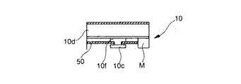
(4)第2、第3実施形態で用いた自動位置変更機構10は、リニアパルスモータの構成を採用していたが、これに代えて、機械的な構成によって可動部10cを駆動してもよい。この場合の一例を図24に示す。図24において、Mはモータであり、50はモータMの軸に、軸心を共通にして取り付けられているボールネジである。10fは受光部2が取り付けられるベース部材であり、ボールネジ50と螺合している。ベース部材10fは、ボールネジが回転すると、その回転方向に応じて図面左右方向に移動する。また、その移動量はボールネジ50の回転量に比例する。また可動部10cには、位置決めセンサ1と脈波検出部5が設けられている。以上の構成により、自動位置変更機構10は、可動部10cを腕の周方向(橈骨動脈に対して直交する方向)に駆動する。
この場合も、第2実施形態と同様に、可動部10cを表皮に押しつけていないので、腕の表皮に沿って移動させる力は少なくて済む。したがって、一般的な超小型モータのトルクで十分にサーボ制御が可能である。また、可動部10cの移動距離は1cm程度あれば、十分に最適位置を見つけることができる。
【0095】
(5)上述した各実施形態および変形例において、摺動体14の端部に押圧脚部2a,2bを設けるようにしても良い。この点について、図25を用いて説明する。図25は光電反射型の脈派検出装置を腕に装着状態での断面図である。この図において、本体18の両端に取り付けられたリストバンド13a,13bは、被験者の手首に巻き付けられて、公知のフック122によって互いに締結されている。なお、フック122により、腕時計10の周長の調節が可能なように、すなわち手首への締め付け力を調節可能なようにされている。
【0096】
リストバンド13aの裏面(手首に対向する面)には光学式拍動検出センサ2’が固定されている。これに代えて圧力検出センサを用いてもよい。光学式拍動検出センサ2’は送信部と受信部が一体となって構成されている。光学式拍動検出センサ2’は、リストバンド13a,13bの締め付け力を受けて橈骨動脈21の真上の表皮を押圧する。
【0097】
リストバンド13aには、裏側に突出する押圧脚部2a,2bが取り付けられており、押圧脚部2a,2bの少なくとも一方はリストバンド13aの周方向に沿って移動可能、かつ移動した位置で停止可能になされている。
この場合、押圧脚部2a,2bは橈骨動脈の両側の弾性の高い(軟らかい)表面を凹ませるから、脈波検出部5を容易に橈骨動脈RAの真上に位置決めすることが可能である。また、可動部10cの先端は、押圧脚部2a,2bの先端同士よりも、上方に位置しているため、他の組織よりも弾性の低い(硬い)橈骨動脈が、押圧脚部2a,2bの間に簡単に位置決めされるようになっている。
【0098】
したがって、このような押圧脚部2a,2bを摺動体14(図4、図13等参照)の端部に設けることによって概略の位置決めを行い、この後、摺動体14によって精密な位置決めを行うことにより、正確な位置決めを容易に行うことができ、脈派信号のSN比を向上することができる。
【0099】
なお、橈骨動脈は皮膚の下3mm程度の位置にあるのが通常であるから、押圧脚部2a,2bのみを用いて皮膚を押圧して位置決めを行っても良い。この場合は、摺動体14と押圧脚部2a,2bを使用する場合と比較して脈派信号のSNは多少劣化するが、実用上問題は少ない。
【0100】
(6)上述した第1実施形態あっては、位置決めセンサ1からの脈波波形MHの極性を極性検出部3で検出して、これを表示部4に表示するようにしたが、脈波波形MHを直接、表示部4に表示してもよい。この場合、脈波検出部5が橈骨動脈の上に位置すると、表示部4に表示される脈波波形MHの振幅極性が反転するので、被験者は脈波検出部5の位置決めを行うことができる。
要は、位置決めセンサ1から出力される脈波波形MHに基づいて、脈波検出手部1と生体の検出部位との相対位置関係を変更するものであれば、如何なる構成を用いてもよい。
【0101】
【発明の効果】
以上、説明したように本発明の発明特定事項によれば、皮膚を押圧ことなく動脈の位置を特定することができるので、被験者に負担をかけることなく、動脈の位置を正確に特定することができ、SN比のよい脈波を検出することができる。
【図面の簡単な説明】
【図1】 橈骨動脈の立体模型図である。
【図2】 橈骨動脈、細動脈および毛細血管の関係を模式的に示す断面図である。
【図3】 橈骨動脈の脈動を示す図である。
【図4】 (a)は毛細血管CAの脈波波形を、(b)は細動脈ARの脈波波形を各々示した図である。
【図5】 本発明の実施形態に係わる脈波検出装置の機能ブロック図である。
【図6】 第1実施形態に係わる脈波検出装置の電気的構成を示すブロック図である。
【図7】 同実施形態に係わる位置決めセンサの回路図である。
【図8】 同実施形態に係わる極性検出部の回路図である。
【図9】 同実施形態に係わる脈波検出装置の外観を示す斜視図である。
【図10】 同実施形態に係わる脈波検出装置を腕に装着した状態を示す斜視図である。
【図11】 同実施形態において脈波波形MHと極性検出信号KSの関係を示す図である。
【図12】 第2実施形態に係わる脈波検出装置の電気的構成を示すブロック図である。
【図13】 同実施形態に係わる自動位置変更機構の外観を示す正面図である。
【図14】 第3実施形態に係わる脈波検出装置の電気的構成を示すブロック図である。
【図15】 同実施形態の体動除去手段7に係わる構成例1を示すブロック図である。
【図16】 同実施形態に係わる第1の周波数解析部71の詳細な構成を示すブロック図である。
【図17】 同実施形態に係わる構成例1の動作を説明するためのタイミングチャートである。
【図18】 同実施形態において、期間Tcにおける脈波解析データMKDを示す図である。
【図19】 同実施形態において、期間Tcにおける体動解析データTKDを示す図である。
【図20】 同実施形態において、体動除去脈波解析データMKD’を示す図である。
【図21】 同実施形態の体動除去手段7に係わるに構成例2を示すブロック図である。
【図22】 人体の動脈を示す図である。
【図23】 変形例に係わる脈波検出装置の外観構成を示す図である。
【図24】 変形例に係わる自動位置変更機構10の機械的な構成を示す図である。
【図25】 光電反射型の脈派検出装置を腕に装着状態での断面図である。
【符号の説明】
1 位置決めセンサ
2 手動位置変更機構(位置変更手段)
3 極性検出部(極性検出手段)
4 表示部(告知手段)
5 脈波検出部(脈波検出手段)
6 制御部(位置変更手段)
7 体動除去手段
8 生態情報生成部(振幅検出手段)
10 自動位置変更機構(位置変更手段)
70 体動検出部
71 第1の周波数解析部
72 第2の周波数解析部
73 体動除去部
74 体動分離部
M,MH 脈波波形
TH 体動波形
MH’体動除去脈波波形[0001]
BACKGROUND OF THE INVENTION
The present invention is a pulse wave detection for detecting a pulse wave. Dress In particular, the present invention relates to a pulse wave detection device capable of detecting a stable pulse wave regardless of the skill level of an operator.
[0002]
[Prior art]
One of the pulse wave detectors detects a radial artery wave. In this type of apparatus, a change in the pressure of the epidermis in the vicinity of the radial artery is detected using a pressure sensor, thereby measuring a pulse wave. In this case, since a change in pressure applied to the sensor placed on the epidermis on the radial artery is detected, it is necessary to apply a pressing force of 30 mmHg to 80 mmHg in order to perform stable pulse wave detection. There was a problem that the feeling was strong.
[0003]
For example, in the invention shown in US Pat. No. 4951679, a pressure sensor placed in the vicinity of the radial artery is pressed against the arm, and the pressure is sequentially changed to maximize the amplitude of the detection signal. Detect the pressing force. The pulse wave is detected with the pressing force. In this case, an optimal pressing force can be set and it is possible to prevent an excessive pressure from being applied, but in any case, a predetermined pressure is applied to the arm, and a feeling of pressure is not changed. The problem of being strong does not go away.
[0004]
On the other hand, there are devices using ultrasonic waves and devices using light (infrared rays, laser light, etc.) as pulse wave detection devices that do not require a strong pressing force. In a pulse wave detection device using an ultrasonic reflected wave, a probe that emits an ultrasonic wave is applied from the outside of the subject's arm, and the ultrasonic wave reflected by an arterial blood vessel or the like is received by the probe and the pulse is received. Perform wave measurements.
[0005]
On the other hand, in a pulse wave detection device that detects light using light, for example, light is transmitted from a light emitting diode toward the body, and the amount of reflected light (reflected light from a subcutaneous tissue or the like) is detected. In this case, since a part of the light emitted from the light emitting diode is absorbed by hemoglobin in the blood vessel, the amount of reflected light is related to the blood volume in the blood vessel and is detected as a pulse wave.
[0006]
[Problems to be solved by the invention]
By the way, in the conventional pulse wave detection device using the ultrasonic wave, the detection value of the reflected wave changes according to the angle formed by the probe that transmits and receives the ultrasonic wave and the blood flow. In the probe operation, it is difficult to maintain a constant angle with respect to the blood flow, and it is difficult to measure a stable pulse wave. For example, when the probe is placed on the palm side of the subject's arm, the detection of the pulse wave becomes difficult because the position of the probe is only a few millimeters away from the arterial blood vessel. Further, when the probe is applied to the back side of the subject's arm, the SN ratio necessary for detecting the pulse wave cannot be ensured.
[0007]
Even in a device using a laser or a light emitting diode, if the irradiation light is not applied to the artery, the S / N ratio required for detecting the pulse waveform cannot be secured, or a stable pulse waveform is detected. Can not do it.
[0008]
The present invention has been made in view of the above-described circumstances, and can detect an accurate and stable pulse wave without forcing the operator to feel pressure and without being affected by the skill level of the operator. An object of the present invention is to provide a pulse wave detection device that can perform this.
[0010]
[Means for Solving the Problems]
To solve the above problem,
[0011]
[0012]
[0013]
[0014]
[0015]
[0016]
[0017]
[0018]
[0019]
[0020]
[0021]
DETAILED DESCRIPTION OF THE INVENTION
A. principle
First, the radial artery position detection method according to the present invention will be described. FIG. 1 is a three-dimensional model of the radial artery. Blood flows through the
FIG. 2 is a cross-sectional view schematically showing the relationship between the radial artery, arteriole and capillary. In this figure, RA is the inner wall of the radial artery composed of the
The capillaries CA and CA ′ have a mesh shape, and supply blood carried by the radial artery to every corner of the tissue. For this reason, the pulse wave waveform detected from the radial artery and the pulse wave waveform detected from the capillary CA have a slight time delay, but their amplitude polarities are the same.
[0022]
By the way, since the blood flow sent out by contraction and expansion of the heart flows in the radial artery, the pulsation as shown in FIG. 3 proceeds toward the peripheral portion at 8 to 16 m / s. Here, when the inner wall RA of the radial artery is expanded by pulsation as in the position X1, the arteriole AR and the capillary vessel CA ′ in the vicinity thereof are compressed by the inner wall RA of the radial artery and become ischemic. On the other hand, when the inner wall RA of the radial artery is not expanded as in the position X2, the arteriole AR and the capillary vessel CA ′ are not compressed by the inner wall RA of the radial artery, so that a normal blood flow flows.
[0023]
For this reason, the pulse wave waveform of the radial artery and the pulse waveform of the arteriole AR and the capillary vessel CA ′ are those in which the amplitude polarity is inverted. On the other hand, as described above, the pulse waveform of the radial artery and the pulse waveform of the capillary vessel CA have the same amplitude polarity. Accordingly, the amplitude waveform of the pulse waveform of the capillary CA and the pulse waveform of the arteriole AR are inverted. FIG. 4A shows the pulse waveform of the capillary CA, and FIG. 4B shows the pulse waveform of the arteriole AR.
[0024]
When a very shallow internal pulse wave waveform is measured from above the skin S around the hand and arm, regions W1 and W3 where the pulse wave waveform of the capillary CA is measured as shown in FIG. 2, and the arterioles AR and capillaries. There is a region W2 where the pulse waveform of CA ′ is measured. Here, when the pulse waveform is measured from the position Xs to the position Xe (in the circumferential direction), the amplitude polarity of the pulse waveform is inverted in the region W2. Therefore, the position of the radial artery can be specified by detecting the position where the amplitude polarity of the pulse wave waveform is reversed.
[0025]
As described above, the present inventors easily identify the position of the radial artery by paying attention to the results of considering the capillaries CA and CA ′, the inner wall RA of the radial artery, and the arteriole AR from the medical viewpoint. A pulse wave detection method was developed. The main point of this pulse wave detection method is that, when detecting a pulse wave waveform from a detection part of a living body using the pulse wave detection means, a light emitting unit that is attached in the vicinity of the pulse wave detection means and irradiates light to the detection part A positioning sensor including a light receiving unit that receives the reflected light is provided, and the relative positional relationship between the pulse wave detecting means and the detection site is changed based on the pulse wave waveform output from the positioning sensor.
[0026]
B. Functional configuration
Next, functions of the pulse wave detection device according to the present embodiment will be described. FIG. 5 is a functional block diagram of the pulse wave detection device according to the present embodiment. In the figure, f1 is a pulse wave detection means for detecting a pulse wave waveform from a detection part of a living body. For example, an optical pulse wave sensor or a pressure sensor is applicable. Further, f2 is an amplitude detecting means for detecting the amplitude value of the pulse wave waveform detected by the pulse wave detecting means.
[0027]
Reference numeral f3 denotes a positioning sensor, which is attached integrally with the pulse wave detection means f1, and is composed of a light emitting unit that irradiates light to the detection site and a light receiving unit that receives the reflected light. The positioning sensor f3 detects the pulse wave waveforms of the capillary CA, the arteriole RA, and the capillary CA '.
[0028]
Further, f4 is a polarity detection means for detecting the amplitude polarity of the pulse waveform output from the positioning sensor f2. Thereby, the position where the amplitude polarity of the pulse wave waveform is inverted can be specified. Further, f5 is a position changing unit that changes the relative positional relationship between the positioning sensor f2, the pulse wave detecting unit f1, and the detection site. As a mode of change, there are one that is operated by the subject and one that automatically performs position control based on the detection result of the polarity detection means f3. When the automatic change is performed, as indicated by a dotted line in the figure, the position changing unit f5 changes the position based on the amplitude polarity detected by the polarity changing unit f4 and the amplitude value detected by the amplitude detecting unit f2.
[0029]
Further, f6 is a notification means, and the pulse wave waveform detected by the pulse wave detection means f1, the biological information indicating the state of the living body obtained based on the pulse wave waveform, the polarity detection means f3 and the amplitude detection means f2 are detected. Announce the results. When the position changing unit f4 is configured manually, the subject can know whether or not the pulse wave detecting unit f1 is in an appropriate position by the notification unit f3.
[0030]
C. First embodiment
Hereinafter, a pulse wave detection device according to a first embodiment of the present invention will be described with reference to the drawings.
1. Configuration of the first embodiment
1-1: Electrical configuration
FIG. 6 is a block diagram showing an electrical configuration of the pulse wave detection device according to the first embodiment. In the figure,
[0031]
As the
[0032]
First, the arteriole AR is formed so as to surround the vascular wall of the radial artery from the outside, and a capillary vessel CA ′ is formed between the inner wall RA of the radial artery and the skin S. For this reason, if the light irradiated for the purpose of detecting the pulse waveform MH of the arteriole AR and the capillary vessel CA ′ reaches the inside of the inner wall RA of the radial artery, the blood flow is detected. As described above, the radial polarity of the pulse waveform of the radial artery and the pulse waveform of the capillary CA are the same, so when the irradiation light reaches the inside of the radial artery RA, the
[0033]
Similarly, light having a wavelength region of 700 nm or less out of the light included in the external light tends not to pass through the tissue of the living body, and therefore the external light is not covered with a light-shielding portion (a band described later). Even when the light is irradiated, the light does not reach the
[0034]
Moreover, hemoglobin in blood has a large extinction coefficient for light having a wavelength of 300 nm to 700 nm, and is several times to about 100 times or more larger than that for light having a wavelength of 880 nm. Therefore, as shown in this example, when light of a wavelength region (300 nm to 700 nm) having a large light absorption characteristic is used as detection light in accordance with the light absorption characteristic of hemoglobin, the detection value changes with sensitivity according to the blood volume change. Therefore, the S / N ratio of the pulse wave waveform MH based on the blood volume change can be increased.
[0035]
Next,
[0036]
Next, 3 is a polarity detection unit that detects the amplitude polarity of the pulse wave waveform MH and outputs a polarity detection signal KS. FIG. 8 is a circuit diagram of the
L1 = + V · R2 / (R1 + R2), L2 = −V · R2 / (R1 + R2)
Accordingly, when the pulse wave waveform MH exceeds the threshold value L1, the polarity detection signal KS becomes a high level, and when the pulse wave waveform MH exceeds the threshold value L2, the polarity detection signal KS becomes a low level.
[0037]
Next, 4 is a display unit, which is constituted by a liquid crystal display device. The biological information such as the amplitude polarity detected by the
[0038]
Next, 5 is a pulse wave detector, which detects the pulsation of the inner wall RA of the radial artery as a pulse wave waveform M. The
[0039]
With the above configuration, when the subject operates the manual
[0040]
1-2: Mechanical configuration
Next, FIG. 9 is a perspective view showing an appearance of the pulse wave detection device according to the present embodiment. As shown in this figure, the present embodiment takes the form of a wristwatch. Here,
[0041]
Further, a pair of
[0042]
In addition, a cable (not shown) is provided between the
[0043]
2. Operation of the first embodiment
Next, the operation of the first embodiment will be described. First, the
[0044]
Here, it is assumed that the sliding
[0045]
The output of the hysteresis comparator becomes high level when the amplitude of the pulse wave waveform MH exceeds the threshold value L1, and becomes low level when the amplitude falls below the threshold value L2. Therefore, the amplitude polarity detection signal KS is as shown in FIG. Become. Here, the periods T1 and T3 in which the amplitude polarity detection signal KS is high level correspond to the areas W1 and W3 shown in FIG. 2, while the low level period T2 corresponds to the area W2 shown in FIG.
[0046]
In this case, “+” is displayed on the
[0047]
After moving the sliding
[0048]
Thereafter, when the pulse wave detection mode is set by operating the
[0049]
3. Modification of the first embodiment
(1) An example of notification means
As described above, according to the present embodiment, the positional relationship between the
[0050]
(2) An example of the positioning method of the
As described above, according to the present embodiment, the position of the pulse
[0051]
C. Second embodiment
1. Configuration of the second embodiment
FIG. 12 is a block diagram showing an electrical configuration of the pulse wave detection device according to the second embodiment. In the present embodiment, an automatic
The automatic
[0052]
Here, FIG. 13 is a front view (skin side) showing the appearance of the automatic
[0053]
2. Operation of the second embodiment
In the above configuration, when the positioning mode is set, the
[0054]
Thereafter, the
[0055]
When the amplitude polarity signal KS is supplied to the
[0056]
When detecting the inversion of the amplitude polarity signal KS, the
[0057]
Thereafter, the
[0058]
Next, the
[0059]
As a result of the above operation, the
[0060]
3. Modified example of the second embodiment
(1) In the second embodiment, the display of the amplitude value on the
[0061]
(2) In the second embodiment, the amplitude value of the pulse wave waveform M detected by the
[0062]
By the way, during exercise such as running, the belt wrapped around the arm may be displaced by the swing of the arm. In such a case, the position of the
[0063]
C: Third embodiment
In the first and second embodiments described above, the amplitude polarity of the pulse wave waveform MH detected by the
[0064]
FIG. 14 shows the electrical configuration of the pulse wave detection device according to the third embodiment. The configuration of the pulse wave detection device is the same as that of the pulse wave detection device of the second embodiment described above, except that the body motion removal means 7 is provided between the
[0065]
1. Configuration example 1
FIG. 15 is a block diagram showing a configuration example 1 of the body
Reference numeral 71 denotes a first frequency analysis unit, which performs frequency analysis on the body motion waveform TH to generate body motion analysis data TKD. On the other hand, 72 is a second frequency analysis unit, which performs frequency analysis on the pulse wave waveform MH and generates pulse wave analysis data MKD. Examples of frequency analysis methods include FFT (Fast Fourier Transform), wavelet transform, and the like. In this example, wavelet transformation will be described as an example.
[0066]
In general, in a time-frequency analysis in which a signal is simultaneously captured from both time and frequency, a wavelet is a unit for cutting out a signal portion. The wavelet transform represents the size of each part of the signal cut out in this unit. In order to define the wavelet transform, a function ψ (x) localized in terms of time and frequency is introduced as a mother wavelet as a basis function. Here, the wavelet transformation of the function f (x) by the mother wavelet ψ (x) is defined as follows.
[Expression 1]
In
[0068]
Here, a detailed configuration of the first frequency analysis unit 71 will be described. FIG. 16 is a block diagram showing a detailed configuration of the first frequency analysis unit 71. The second
[0069]
First, when the mother wavelet ψ (x) is read from the basis function storage unit W1, the scale conversion unit W2 converts the scale parameter a. Here, since the scale parameter a corresponds to the period, the mother wavelet ψ (x) is expanded on the time axis when a increases. In this case, since the amount of data of the mother wavelet ψ (x) stored in the basis function storage unit W1 is constant, the amount of data per unit time decreases as a increases. The scale conversion unit W2 performs an interpolation process so as to compensate for this, and performs a thinning process when a becomes smaller to generate a function ψ (x / a). This data is temporarily stored in the buffer memory W3.
[0070]
Next, the translation unit W4 reads the function ψ (x / a) from the buffer memory W3 at a timing according to the translation parameter b, thereby translating the function ψ (x / a) and performing the function ψ (x−a). b / a) is generated.
[0071]
Next, body motion waveform data THD obtained by A / D converting the body motion waveform TH via an A / D converter (not shown) is supplied to the multiplication unit W5. The multiplication unit W4 is a variable 1 / a 1/2 , Function ψ (x−b / a) and body motion waveform data THD are multiplied to perform wavelet transform to generate body motion analysis data TKD. In this example, body motion waveform data TKD is 0 Hz to 0.5 Hz, 0.5 Hz to 1.0 Hz, 1.0 Hz to 1.5 Hz, 1.5 Hz to 2.0 Hz, 2.0 Hz to 2.5 Hz, 2 The output is divided into frequency regions such as .5 Hz to 3.0 Hz, 3.0 Hz to 3.5 Hz, and 3.5 Hz to 4.0 Hz. The second
[0072]
Next,
[Expression 2]
Here, the operation of the configuration example 1 will be described with reference to the drawings. In this example, it is assumed that the user lifts the cup by hand and then returns it to its original position. In this case, the pulse wave waveform MH shown in FIG. 17 (a) is detected by the
[0074]
Here, the body motion waveform TH starts to increase from time T1, reaches a positive peak at time T2, then gradually decreases, passes
[0075]
Next, the operation of the pulse wave detection device in the period Tc shown in FIG. 17 will be described with reference to FIGS. FIG. 18 shows pulse wave analysis data MKD in the period Tc, and FIG. 18 shows body motion analysis data TKD in the period Tc. From this figure, it can be seen that the body motion waveform TH includes a relatively large level of frequency components in the frequency range of 0.0 Hz to 1.0 Hz.
[0076]
When the pulse wave analysis data MKD and the body motion analysis data TKD are supplied to the body
[0077]
As described above, in the configuration example 1, based on the body motion waveform TH detected by the body
[0078]
2. Configuration example 2
In the configuration example 1, the body motion waveform TH is detected by the body
[0079]
FIG. 21 is a block diagram showing a configuration example 2 of the body
[0080]
The body movement is caused by the vertical movement of the arm, the swing of the arm during running, etc., but in daily life, the human body is hardly moved instantaneously. For this reason, in daily life, the frequency component of the body motion waveform TH is not so high and is usually in the range of 0 Hz to 1 Hz. In this case, the fundamental frequency of the pulse wave waveform MH is often in the range of 1 Hz to 2 Hz. Therefore, in daily life, the frequency component of the body motion waveform TH is in a frequency region lower than the fundamental frequency of the pulse wave waveform MH.
[0081]
On the other hand, during sports such as jogging, the frequency component of the body movement waveform TH is somewhat higher due to the influence of arm swinging, etc., but the heart rate increases according to the amount of exercise, so the pulse wave waveform The fundamental frequency of MH also increases at the same time. For this reason, even during sports, the frequency component of the body movement waveform TH is usually in a frequency region lower than the fundamental frequency of the pulse wave waveform MH.
[0082]
The body
[0083]
In FIG. 21, the
[0084]
Next, the
[0085]
As described above, in the configuration example 2, the body motion removal pulse wave waveform MH ′ is generated by the body
[0086]
3. Modification of the third embodiment
(1) In the third embodiment described above, body movement is removed from the pulse wave waveform MH from the
[0087]
(2) In the third embodiment described above, the pulse wave detection device having the automatic
[0088]
(3) In the third embodiment described above, the output of the wavelet transform has a fixed relationship between each frequency domain and the time domain, so the detection time is determined according to the frequency domain to be divided. For this reason, it is preferable to intermittently drive the automatic
[0089]
D. Modified example
The present invention is not limited to the above-described embodiments, and various modifications described below are possible.
(1) In each of the above-described embodiments, the radial artery of the wrist has been described as an example of the living body part for detecting the pulse group. The corresponding artery may be any type. That is, there are various types of human arteries as shown in FIG. 22, and if the form of the pulse group detection device described above is modified in accordance with the detection site, various arteries can be positioned, An accurate pulse wave waveform can be detected.
[0090]
For example, when the pulse wave waveform M is detected from the neck carotid artery, it may be configured as shown in FIG. In this figure,
[0091]
Moreover, it may replace with the automatic
[0092]
(2) Although each embodiment mentioned above took up the pressure sensor as an example of the pulse
[0093]
(3) In each of the above-described embodiments, the
[0094]
(4) The automatic
Also in this case, as in the second embodiment, since the
[0095]
(5) In each of the above-described embodiments and modifications, the
[0096]
An optical pulsation detection sensor 2 'is fixed to the back surface (the surface facing the wrist) of the
[0097]
The
In this case, since the
[0098]
Therefore, rough positioning is performed by providing such
[0099]
Since the radial artery is usually located at a position of about 3 mm below the skin, the positioning may be performed by pressing the skin using only the
[0100]
(6) In the first embodiment described above, the polarity of the pulse wave waveform MH from the
In short, any configuration may be used as long as it changes the relative positional relationship between the pulse wave
[0101]
【The invention's effect】
As described above, according to the invention specifying matters of the present invention, the position of the artery can be specified without pressing the skin, so that the position of the artery can be accurately specified without placing a burden on the subject. And a pulse wave with a good S / N ratio can be detected.
[Brief description of the drawings]
FIG. 1 is a three-dimensional model of a radial artery.
FIG. 2 is a cross-sectional view schematically showing the relationship between radial arteries, arterioles and capillaries.
FIG. 3 is a diagram showing pulsation of the radial artery.
4A is a diagram showing a pulse waveform of a capillary CA, and FIG. 4B is a diagram showing a pulse waveform of an arteriole AR.
FIG. 5 is a functional block diagram of a pulse wave detection device according to an embodiment of the present invention.
FIG. 6 is a block diagram showing an electrical configuration of the pulse wave detection device according to the first embodiment.
FIG. 7 is a circuit diagram of a positioning sensor according to the same embodiment.
FIG. 8 is a circuit diagram of a polarity detection unit according to the embodiment.
FIG. 9 is a perspective view showing an appearance of the pulse wave detection device according to the embodiment.
FIG. 10 is a perspective view showing a state in which the pulse wave detection device according to the embodiment is mounted on the arm.
FIG. 11 is a diagram showing a relationship between a pulse wave waveform MH and a polarity detection signal KS in the same embodiment.
FIG. 12 is a block diagram showing an electrical configuration of the pulse wave detection device according to the second embodiment.
FIG. 13 is a front view showing the appearance of the automatic position changing mechanism according to the embodiment.
FIG. 14 is a block diagram showing an electrical configuration of a pulse wave detection device according to a third embodiment.
FIG. 15 is a block diagram showing a configuration example 1 relating to body movement removing means 7 of the same embodiment;
FIG. 16 is a block diagram showing a detailed configuration of a first frequency analysis unit 71 according to the embodiment.
FIG. 17 is a timing chart for explaining an operation of the configuration example 1 according to the embodiment;
FIG. 18 is a diagram showing pulse wave analysis data MKD in a period Tc in the embodiment.
FIG. 19 is a diagram showing body motion analysis data TKD in a period Tc in the same embodiment.
FIG. 20 is a diagram showing body motion removal pulse wave analysis data MKD ′ in the same embodiment.
FIG. 21 is a block diagram showing a configuration example 2 relating to the body
FIG. 22 is a diagram showing an artery of a human body.
FIG. 23 is a diagram showing an external configuration of a pulse wave detection device according to a modified example.
FIG. 24 is a diagram showing a mechanical configuration of an automatic
FIG. 25 is a cross-sectional view of a photoelectric reflection type pulse group detection device attached to an arm.
[Explanation of symbols]
1 Positioning sensor
2 Manual position change mechanism (position change means)
3 Polarity detection unit (polarity detection means)
4 display part (notification means)
5 Pulse wave detector (pulse wave detector)
6 Control unit (position changing means)
7 Body motion removal means
8 Ecological information generator (amplitude detection means)
10 Automatic position change mechanism (position change means)
70 Body motion detector
71 1st frequency analysis part
72 Second frequency analysis unit
73 Body movement removal unit
74 Body motion separation part
M, MH pulse waveform
TH body movement waveform
MH 'body motion elimination pulse wave waveform
Claims (16)
前記脈波検出手段の近傍に取り付けられ、前記検出部位に光を照射する発光部とその反射光を受光する受光部とからなる位置決めセンサと、
前記位置決めセンサおよび前記脈波検出手段と、
前記検出部位との相対位置関係を変更する位置変更手段と、
前記位置決めセンサから出力される脈波波形の振幅極性を検出する極性検出手段と、
前記極性検出手段の検出結果を告知する告知手段と
を備えることを特徴とする脈波検出装置。Pulse wave detection means for detecting a pulse wave waveform from a detection site of a living body;
A positioning sensor that is attached in the vicinity of the pulse wave detection means and includes a light emitting unit that irradiates light to the detection site and a light receiving unit that receives the reflected light;
The positioning sensor and the pulse wave detection means;
Position changing means for changing the relative positional relationship with the detection site;
Polarity detection means for detecting the amplitude polarity of the pulse waveform output from the positioning sensor;
A pulse wave detection device comprising: notification means for notifying a detection result of the polarity detection means.
前記脈波検出手段の近傍に取り付けられ、前記検出部位に光を照射する発光部とその反射光を受光する受光部とからなる位置決めセンサと、
前記位置決めセンサから出力される脈波波形の振幅極性を検出する極性検出手段と、
前記極性検出手段によって検出される振幅極性が反転するように、前記位置決めセンサおよび前記脈波検出手段と前記検出部位との相対位置関係を変更する位置変更手段と
を備えることを特徴する脈波検出装置。Pulse wave detection means for detecting a pulse wave waveform from a detection site of a living body;
A positioning sensor that is attached in the vicinity of the pulse wave detection means and includes a light emitting unit that irradiates light to the detection site and a light receiving unit that receives the reflected light;
Polarity detection means for detecting the amplitude polarity of the pulse waveform output from the positioning sensor;
A pulse wave detection comprising: a positioning sensor and a position changing means for changing a relative positional relationship between the pulse wave detecting means and the detection part so that the amplitude polarity detected by the polarity detecting means is reversed. apparatus.
前記極性検出手段は、前記体動除去脈波波形に基づいて極性を検出することを特徴とする請求項1または2に記載の脈波検出装置。Body movement removing means for removing body movement from the pulse wave waveform detected by the positioning sensor to generate a body movement removal pulse wave waveform;
It said polarity detection means, a pulse wave detection device according to claim 1 or 2, characterized in that detecting the polarity based on said body movement eliminated pulse waveform.
前記脈波検出手段の近傍に取り付けられ、前記検出部位に光を照射する発光部とその反射光を受光する受光部とからなる位置決めセンサと、
前記位置決めセンサと前記検出部位との相対位置関係を変更する位置変更手段と、
前記位置決めセンサから出力される脈波波形の振幅極性を検出する極性検出手段と、
前記位置決めセンサから出力される脈波波形の振幅を検出する振幅検出手段と、
前記極性検出手段の検出結果と前記振幅検出手段の検出結果を告知する告知手段と
を備えることを特徴とする脈波検出装置。Pulse wave detection means for detecting a pulse wave waveform from a detection site of a living body;
A positioning sensor that is attached in the vicinity of the pulse wave detection means and includes a light emitting unit that irradiates light to the detection site and a light receiving unit that receives the reflected light;
Position changing means for changing a relative positional relationship between the positioning sensor and the detection site;
Polarity detection means for detecting the amplitude polarity of the pulse waveform output from the positioning sensor;
Amplitude detecting means for detecting the amplitude of the pulse waveform output from the positioning sensor;
A pulse wave detection device comprising: a detection result for notifying a detection result of the polarity detection means and a detection result of the amplitude detection means.
前記脈波検出手段の近傍に取り付けられ、前記検出部位に光を照射する発光部とその反射光を受光する受光部とからなる位置決めセンサと、
前記位置決めセンサおよび前記脈波検出手段と、
前記検出部位との相対位置関係を変更する位置変更手段と、
前記位置決めセンサから出力される脈波波形の振幅極性を検出する極性検出手段と、
前記位置決めセンサから出力される脈波波形の振幅を検出する振幅検出手段と、
前記極性検出手段によって検出される振幅極性が反転し、かつ、前記振幅検出手段によって検出される振幅が最大となるように、前記位置決めセンサおよび前記脈波検出手段と、
前記検出部位との相対位置関係を変更する位置変更手段と
を備えることを特徴とする脈波検出装置。Pulse wave detection means for detecting a pulse wave waveform from a detection site of a living body;
A positioning sensor that is attached in the vicinity of the pulse wave detection means and includes a light emitting unit that irradiates light to the detection site and a light receiving unit that receives the reflected light;
The positioning sensor and the pulse wave detection means;
Position changing means for changing the relative positional relationship with the detection site;
Polarity detection means for detecting the amplitude polarity of the pulse waveform output from the positioning sensor;
Amplitude detecting means for detecting the amplitude of the pulse waveform output from the positioning sensor;
The positioning sensor and the pulse wave detection means so that the amplitude polarity detected by the polarity detection means is reversed and the amplitude detected by the amplitude detection means is maximized;
And a position changing means for changing a relative positional relationship with the detection site.
前記極性検出手段は前記体動除去脈波波形に基づいて極性を検出するとともに、前記振幅検出手段は前記体動除去脈波波形に基づいて振幅を検出する
ことを特徴とする請求項4または5に記載の脈波検出装置。Body movement removing means for removing body movement from the pulse wave waveform from the positioning sensor to generate a body movement removal pulse wave waveform;
Together with the polarity detection means detects the polarity based on said body movement eliminated pulse wave waveform, claim 4 or 5 amplitude detecting means and detects an amplitude based on said body movement eliminated pulse wave waveform The pulse wave detection device according to 1.
前記生体の体動を検出する体動検出部と、
前記体動検出部によって検出された体動波形の周波数解析を行う第1の周波数解析部と、
前記位置決めセンサからの脈波波形の周波数解析を行う第2の周波数解析部と、
前記第1の周波数解析部によって解析された周波数解析結果と、
前記第2の周波数解析部によって解析された周波数解析結果とを比較して、前記体動除去脈波波形を生成する体動除去部と
を備えたことを特徴とする請求項3または6に記載の脈波検出装置。The body movement removing means includes
A body motion detector for detecting body motion of the living body;
A first frequency analysis unit that performs frequency analysis of a body motion waveform detected by the body motion detection unit;
A second frequency analysis unit that performs frequency analysis of a pulse waveform from the positioning sensor;
A frequency analysis result analyzed by the first frequency analysis unit;
By comparing the frequency analysis result analyzed by the second frequency analysis unit, according to claim 3 or 6, characterized in that a body movement elimination section that generates the body movement eliminated pulse wave waveform Pulse wave detector.
前記位置決めセンサからの脈波波形の周波数解析を行う周波数解析部と、
前記周波数解析部によって解析された周波数解析結果のうち低域成分を除去した周波数成分に基づいて、前記体動除去脈波波形を生成する体動分離部と
を備えたことを特徴とする請求項3または6に記載の脈波検出装置。The body movement removing means includes
A frequency analysis unit that performs frequency analysis of a pulse waveform from the positioning sensor;
A body motion separation unit that generates the body motion removal pulse wave waveform based on a frequency component obtained by removing a low frequency component from the frequency analysis result analyzed by the frequency analysis unit. 7. The pulse wave detection device according to 3 or 6 .
Priority Applications (1)
| Application Number | Priority Date | Filing Date | Title |
|---|---|---|---|
| JP23499497A JP3820699B2 (en) | 1997-08-29 | 1997-08-29 | Pulse wave detector |
Applications Claiming Priority (1)
| Application Number | Priority Date | Filing Date | Title |
|---|---|---|---|
| JP23499497A JP3820699B2 (en) | 1997-08-29 | 1997-08-29 | Pulse wave detector |
Publications (2)
| Publication Number | Publication Date |
|---|---|
| JPH1170087A JPH1170087A (en) | 1999-03-16 |
| JP3820699B2 true JP3820699B2 (en) | 2006-09-13 |
Family
ID=16979492
Family Applications (1)
| Application Number | Title | Priority Date | Filing Date |
|---|---|---|---|
| JP23499497A Expired - Fee Related JP3820699B2 (en) | 1997-08-29 | 1997-08-29 | Pulse wave detector |
Country Status (1)
| Country | Link |
|---|---|
| JP (1) | JP3820699B2 (en) |
Families Citing this family (12)
| Publication number | Priority date | Publication date | Assignee | Title |
|---|---|---|---|---|
| JP3722203B2 (en) | 2000-06-14 | 2005-11-30 | 株式会社デンソー | Pulse wave sensor |
| JP2002049979A (en) * | 2000-08-03 | 2002-02-15 | Seiko Precision Inc | Automatically emergency warning device and method for automatically outputting emergency warning |
| JP4845303B2 (en) * | 2001-05-31 | 2011-12-28 | セイコーインスツル株式会社 | Pulse meter |
| JP3972141B2 (en) * | 2002-05-09 | 2007-09-05 | オムロンヘルスケア株式会社 | Pulse meter |
| JP4306382B2 (en) | 2003-01-23 | 2009-07-29 | オムロンヘルスケア株式会社 | Pulse wave measuring device |
| JP6010982B2 (en) * | 2012-04-04 | 2016-10-19 | セイコーエプソン株式会社 | Biological information measuring device |
| JP6224526B2 (en) | 2014-05-28 | 2017-11-01 | 京セラ株式会社 | Measuring apparatus and measuring method |
| JP6658332B2 (en) * | 2016-06-23 | 2020-03-04 | オムロンヘルスケア株式会社 | Sphygmomanometer |
| JP6633040B2 (en) * | 2017-10-05 | 2020-01-22 | 京セラ株式会社 | Measuring device and measuring method |
| JP2018027324A (en) * | 2017-10-05 | 2018-02-22 | 京セラ株式会社 | Measuring device and measuring method |
| JP6454050B1 (en) * | 2018-09-20 | 2019-01-16 | 秀昭 松▲崎▼ | Vaginal vital sign measuring instrument |
| FI128751B (en) * | 2019-01-09 | 2020-11-30 | Turun Yliopisto | An apparatus for measuring functionality of an arterial system |
-
1997
- 1997-08-29 JP JP23499497A patent/JP3820699B2/en not_active Expired - Fee Related
Also Published As
| Publication number | Publication date |
|---|---|
| JPH1170087A (en) | 1999-03-16 |
Similar Documents
| Publication | Publication Date | Title |
|---|---|---|
| JP3882204B2 (en) | Pulse wave detector | |
| EP2291111B1 (en) | Contactless respiration monitoring of a patient and optical sensor for a photoplethysmography measurement | |
| JP3951708B2 (en) | Biological information evaluation device | |
| JP3843462B2 (en) | Pulse wave diagnostic device | |
| JP3820699B2 (en) | Pulse wave detector | |
| CN116568208A (en) | Non-invasive blood pressure estimation and vessel monitoring based on photoacoustic plethysmography | |
| CN103961080B (en) | Bioinformation detecting device and Biont information detection method | |
| JP3940150B2 (en) | Caffres electronic blood pressure monitor | |
| WO2001000087A9 (en) | Method and apparatus for the noninvasive determination of arterial blood pressure | |
| WO1997038626A1 (en) | Arrhythmia detector | |
| JP2014217707A (en) | Biological information measuring device and biological information measuring system | |
| JPWO2018043692A1 (en) | Blood pressure measurement device, blood pressure measurement method, and recording medium recording blood pressure measurement program | |
| JP2017510411A (en) | Method for determining blood pressure in a blood vessel and apparatus for performing the method | |
| JPH1156827A (en) | Exercise intensity detector | |
| US20150243190A1 (en) | Blood pressure measurement apparatus | |
| JP3870514B2 (en) | Stroke volume detection device and cardiac function diagnosis device | |
| JP3666188B2 (en) | Cardiac function diagnostic device | |
| JP4759860B2 (en) | Anoxic work threshold detection device | |
| JP3858379B2 (en) | Cardiac output detection device and cardiac function diagnosis device | |
| JP2010207344A (en) | Blood pressure/blood velocity state determination device and method for determining the same | |
| JP3533122B2 (en) | Pulse wave monitor | |
| JPS6384520A (en) | Reflection type heart rate meter | |
| US11389075B2 (en) | Veterinary pulse probe | |
| JP2003210425A (en) | Circulatory dynamics measuring instrument | |
| JP2681151B2 (en) | Sphygmomanometer probe and blood pressure measuring device |
Legal Events
| Date | Code | Title | Description |
|---|---|---|---|
| A977 | Report on retrieval |
Free format text: JAPANESE INTERMEDIATE CODE: A971007 Effective date: 20041130 |
|
| A131 | Notification of reasons for refusal |
Free format text: JAPANESE INTERMEDIATE CODE: A131 Effective date: 20051129 |
|
| A521 | Written amendment |
Free format text: JAPANESE INTERMEDIATE CODE: A523 Effective date: 20060112 |
|
| TRDD | Decision of grant or rejection written | ||
| A01 | Written decision to grant a patent or to grant a registration (utility model) |
Free format text: JAPANESE INTERMEDIATE CODE: A01 Effective date: 20060530 |
|
| A61 | First payment of annual fees (during grant procedure) |
Free format text: JAPANESE INTERMEDIATE CODE: A61 Effective date: 20060612 |
|
| R150 | Certificate of patent or registration of utility model |
Free format text: JAPANESE INTERMEDIATE CODE: R150 |
|
| FPAY | Renewal fee payment (event date is renewal date of database) |
Free format text: PAYMENT UNTIL: 20100630 Year of fee payment: 4 |
|
| FPAY | Renewal fee payment (event date is renewal date of database) |
Free format text: PAYMENT UNTIL: 20110630 Year of fee payment: 5 |
|
| FPAY | Renewal fee payment (event date is renewal date of database) |
Free format text: PAYMENT UNTIL: 20110630 Year of fee payment: 5 |
|
| FPAY | Renewal fee payment (event date is renewal date of database) |
Free format text: PAYMENT UNTIL: 20120630 Year of fee payment: 6 |
|
| FPAY | Renewal fee payment (event date is renewal date of database) |
Free format text: PAYMENT UNTIL: 20130630 Year of fee payment: 7 |
|
| FPAY | Renewal fee payment (event date is renewal date of database) |
Free format text: PAYMENT UNTIL: 20130630 Year of fee payment: 7 |
|
| LAPS | Cancellation because of no payment of annual fees |