JP3805930B2 - Container cover and container with container cover - Google Patents
Container cover and container with container cover Download PDFInfo
- Publication number
- JP3805930B2 JP3805930B2 JP22256799A JP22256799A JP3805930B2 JP 3805930 B2 JP3805930 B2 JP 3805930B2 JP 22256799 A JP22256799 A JP 22256799A JP 22256799 A JP22256799 A JP 22256799A JP 3805930 B2 JP3805930 B2 JP 3805930B2
- Authority
- JP
- Japan
- Prior art keywords
- container
- fixing frame
- engaging portion
- cover
- mountain cap
- Prior art date
- Legal status (The legal status is an assumption and is not a legal conclusion. Google has not performed a legal analysis and makes no representation as to the accuracy of the status listed.)
- Expired - Fee Related
Links
Images


Landscapes
- Containers And Packaging Bodies Having A Special Means To Remove Contents (AREA)
- Closures For Containers (AREA)
Description
【0001】
【発明の属する利用分野】
本発明は、容器カバー及び容器カバー付き容器に関するものである。
【0002】
【従来の技術】
化粧品類をはじめ、各種薬剤や溶液等を詰めたエアゾール容器等の容器では、その頭部に、内容物の取出機能を有する容器カバーが装着されている。
この容器カバーは、容器の頭部に設けられた内容物取出用のステムに対して嵌着される噴出操作部と、この噴出操作部を除いて容器の頭部を被蓋するカバー本体とを有した構成となっており、噴出操作部による内容物の取出形態として、ムースタイプとスプレータイプとに大別される。
【0003】
なお、噴出操作部とカバー本体とは、互いに一体形成されている場合や、それぞれ別部材であるが不可分一体に組み立てられている場合、及び別部材を別個独立した状態で容器に組み付けられている場合がある。
このような容器カバーは一般にプラスチック製であり、これに対して容器はアルミやスチール等の金属製であるか又はガラス製である。従って、環境問題が叫ばれている昨今では、使用済み後の廃棄時にこれら容器カバーと容器とを分別することが使用者側に求められている。
【0004】
ところで、容器の頭部には、上記ステムを囲むようにして環状のマウンテンキャップが設けられており、容器カバーは、このマウンテンキャップを外嵌しつつ係合する円筒形の固定枠を有して、この固定枠を介して容器に装着するものとなっている。
従来、このような構造で容器に装着されている容器カバーを、その廃棄時に取り外せるようにするためには、固定枠における周方向の一部に当初より切欠を設けておくと共に、この切欠に対応する外周面位置又は天面に、この切欠をステム位置方向へ向けて側方押圧させるべく促す表示部を設ける構造を採用していた(特開平10−17040号公報、特開平10−167356号公報、特開平10−230197号公報、特開平10−245082号公報等参照)。
【0005】
【発明が解決しようとする課題】
従来において、容器から容器カバーを取り外すために採られていた上記の構造では、固定枠の周方向一部に切欠を設けているため、この切欠では当然のことながらマウンテンキャップとの係合は行われていないことになる。
従って、このことが必要時における容器カバーの取り外しを容易にしているものであるが、裏を返せば、この切欠では意図しないとき(廃棄時でないとき)でも容器カバーを外れ易くするから、実際に、容器の一般的な取り扱い中であるにも拘わらず、容器から容器カバーが外れてしまうということがあった。
【0006】
本発明は、上記事情に鑑みてなされたものであって、廃棄時等の必要時には簡単に容器カバーを容器から取り外すことができるようにし、しかし必要時以外には容器から容器カバーが簡単に外れてしまうことがないようにできる容器カバー及び容器カバー付き容器を提供することを目的とする。
【0007】
【課題を解決するための手段】
本発明では、上記目的を達成するために、次の技術的手段を講じた。
即ち、本発明に係る容器カバーは、内容物取出用ステムとこのステムを囲む環状のマウンテンキャップとが設けられた容器の頭部に装着されるものであって、上記ステムに嵌着される噴出操作部と、この噴出操作部を除いて上記容器の頭部を被蓋するカバー本体とを有している。
そして、このうちカバー本体は、上記マウンテンキャップに内嵌して係合可能となる内固定枠と、マウンテンキャップに外嵌して係合可能となる外固定枠と、これら内外固定枠を連結する天枠とを有している。すなわち、少なくとも内固定枠と外固定枠との二重の固定枠を有したものである。
【0008】
また、上記外固定枠には、周方向の少なくとも1か所にマウンテンキャップに対する非係合部が設けられていると共に、上記内固定枠には、外固定枠の非係合部からステム位置を介した対称位置にマウンテンキャップに対する非係合部が設けられている。
この場合、外固定枠においては、内固定枠の非係合部とほぼ対応する部位で、この外固定枠がマウンテンキャップに係合可能な状態を確保されていることが重要とされる。また、内固定枠においては、外固定枠の非係合部とほぼ対応する部位で、この内固定枠がマウンテンキャップに係合可能な状態を確保されていることが重要とされる。
【0009】
このような構成であると、外固定枠において非係合部が設けられた部分では内固定枠がマウンテンキャップに係合しており、また内固定枠において非係合部が設けられた部分では外固定枠がマウンテンキャップに係合していることになるため、結果として、外固定枠及び内固定枠の共同体として、マウンテンキャップにほぼ全周的に係合していることになる。
そのため、廃棄時等の必要時には外固定枠において非係合部が設けられた位置に対応して側面押圧すれば、容器カバーを容器から簡単に取り外すことができるものであり、必要時以外では(意欲をもって外そうとしない限りは)、容器から容器カバーが外れないもの、或いは外れ難いものとなる。
【0010】
カバー本体には、外固定枠の非係合部が設けられた周方向位置に対応して、側方押圧を促す表示部を設けておくのが好ましい。
このようにすることで、操作位置を見つけや易くなる。
内固定枠の非係合部は、マウンテンキャップには未当接となる切欠として形成しておくのが好適である。
このようにすることで、一層、外しやすくなる。
カバー本体に対して外固定枠を被覆する肩カバー部が設けられている場合であれば、前記外固定枠の非係合部は、マウンテンキャップには未当接となる切欠として形成しておくのが好適である。
【0011】
このようにすることで、一層、外しやすくなる。
外固定枠の非係合部及び前記内固定枠の非係合部は、周方向に複数設けておくことができる。
このようにすれば、操作位置が多くなることに伴って操作位置を見つけやすいと言うことに繋がり、結果として外しやすいことになる。また、外固定枠や内固定枠において可撓性が増すことに繋がるため、このことも、外しやすさを助長するものとなる。
【0012】
一方、本発明に係る容器カバー付き容器では、上記構成の容器カバーを容器頭部に装着したものであり、上記作用効果を得ることができるものである。
【0013】
【発明の実施の形態】
以下、図面に基づいて本発明の実施の形態を説明する。
図1乃至図4は、本発明に係る容器カバー1の第1実施形態を示している。
図2及び図3に示すように、この容器カバー1は、噴出操作部2とカバー本体3とを有したもので、噴出操作部2は、容器5の頭部5aに設けられた内容物取出用のステム6に対して嵌着されるようになっており、またカバー本体3は、この噴出操作部2を除いて容器5の頭部5aを被蓋するようになっている。
【0014】
この第1実施形態において、噴出操作部2における内容物の取出形態はムースタイプとされており、従ってこの噴出操作部2は、やや先細りとなるパイプ状に形成され、その根元部には側方へ膨出するかたちで押釦部7が設けられている。
噴出操作部2の根元部まわりには、細幅に形成された1か所の連結部8を除いて略1周する周溝9が設けられている。すなわち、これら噴出操作部2及びカバー本体3は、連結部8を介して互いに一体形成されている。これらの形成素材としては、ポリプロピレン、ポリエチレン、ABS等の適宜プラスチックが用いられている。
【0015】
従って、連結部8にはある程度の可撓性が与えられた状態となり、この可撓性に基づき、噴出操作部2は、押釦部7を下方へ押したときに傾動自在となっている。この噴出操作部2の傾動により、容器5のステム6を押して容器5の内容物を噴出させるものである。
なお、容器5は、アルミやスチール等の金属製、又はガラス製とされており、その頭部5aには、上記したステム6を囲むようにして環状のマウンテンキャップ12が設けられている。
【0016】
上記カバー本体3は、容器5のマウンテンキャップ12を利用して、これに係合することで容器5の頭部5aに装着されるようになっている。すなわち、このカバー本体3は内固定枠13と外固定枠14、及びこれら内外固定枠13,14を連結する天枠15並びに外固定枠14のまわりを被覆する肩カバー部16とを有している。
なお、肩カバー部16は、容器5の外周面をそのまま同径で立ち上げた状態とし、そのうえで外膨らみ状のアールを伴いながら中心方向へ延びて外固定枠14のまわりを被覆するようになっている。
【0017】
内固定枠13は、マウンテンキャップ12に内嵌可能な直径を有する円筒形に形成されたもので、その下端部の外周面には、径方向外方へ少しだけ膨出して上記マウンテンキャップ12の内周部に係合可能となる係合凸条17が設けられている。
また外固定枠14は、マウンテンキャップ12に外嵌可能な直径を有する円筒形に形成されたもので、その下端部の内周面には、径方向内方へ少しだけ膨出して上記マウンテンキャップ12の外周部に係合可能となる係合凸条18が設けられている。
【0018】
図3及び図4に示すように、上記外固定枠14には、その周方向の1か所に、マウンテンキャップ12には未当接となる切欠20が設けられている。この切欠20の部分では、同時に係合凸条18も除去されたかたちになるので、これによってマウンテンキャップ12に対する非係合部21が形成されることになる。
また、上記内固定枠13でも同じように、その周方向の1か所に、マウンテンキャップ12には未当接となる切欠23が設けられている。この切欠23の部分では、同時に係合凸条17も除去されたかたちになるので、これによってマウンテンキャップ12に対する非係合部24が形成されることになる。
【0019】
そして、外固定枠14に設けられる非係合部21と、内固定枠13に設けられる非係合部24とは、互いにステム6の位置を介した対称位置に配されたものとなっている。
外固定枠14において、その非係合部21が設けられる部分以外は、全て、この外固定枠14がマウンテンキャップ12に係合可能な状態を確保されていることになり、また内固定枠13において、その非係合部24が設けられる部分以外は、全て、この内固定枠13がマウンテンキャップ12に係合可能な状態を確保されていることになるので、その結果、外固定枠14の非係合部21位置では必ず内固定枠13がマウンテンキャップ12に係合し、また内固定枠13の非係合部24位置では必ず外固定枠14がマウンテンキャップ12に係合するようになる。
【0020】
すなわち、このカバー本体3は、これら内外固定枠13,14の共同体として、マウンテンキャップ12に全周的に係合していることになる。従って、容器5からカバ−体1が簡単に外れてしまうということはない。
また、このように内外固定枠13,14による二重構造にすると、容器5に対する容器カバー1の回転を抑えることができるようになり、それだけ容器5として使いやすくなると共に、このような回転を原因として内固定枠13や外固定枠14が変形を起こすこともなくなり、意図しないときに容器5からカバ−体1が外れるのを防止する効果も、それだけ高くなる。
【0021】
なお、図2に示すように、カバー本体3の天枠15上面や肩カバー部16の上面又は外周面には、外固定枠14において非係合部21が設けられている周方向位置に対応して、この位置を側方押圧するように促すための表示部25,26が設けられている。
この表示部25,26は、矢印や星印、円形、多角形等の図形又は文字でもよく、またその設け方も、成形と同時の浮き出し又は凹ませによるものをはじめ、成型後の刻印、着色、印刷、シール貼付等、適宜方法を採用可能である。
【0022】
また、2つの表示部25,26は、いずれか一方だけ設けるだけでも足りる。
このような構成の容器カバー1にあって、いまこの容器カバー1が容器5の頭部5aに装着された状態にあるものとして、容器5の内容物を使いきったことによって廃棄するのに先駆けて、この容器カバー1を容器5から取り外す場合を説明する。
容器カバー1を外すには、外固定枠14において非係合部21が設けられている周方向位置に対応して、この位置を側方押圧するようにするが、このとき、天枠15の上面に設けられた表示部25にしたがって、図3及び図1中に矢符Xで示すように噴出操作部2の側面を横押ししたとする。
【0023】
すると、噴出操作部2は、ステム6を押し込む範囲を超えて傾動するようになり、これに伴って容器カバー1全体に横移動しようとする力が加えられる。このとき、この横移動方向の先方側では、マウンテンキャップ12の内周部に対して内固定枠13の非係合部24が対応しており、従ってこのマウンテンキャップ12の内アールに沿いつつ非係合部24、即ち、切欠23における周方向両側の開口縁部が幅詰め状に対向接近されるようになる。
そのため、内固定枠13は縮径状態となり、これに伴って容器カバー1全体としての上記横移動状況は、一層、進行されることになる。
【0024】
これに対し、容器カバー1全体の横移動における横移動方向の後方側では、マウンテンキャップ12の外周部に対して外固定枠14の非係合部21が対応しており、従って容器カバー1全体としての上記横移動に支障は生じないものとなっている。
このようなことから、容器カバー1は上記の横移動によって、簡単に、容器5から取り外せることになる。
一方、容器カバー1を外すときに、肩カバー部16の上面に設けられた表示部26にしたがって、図3及び図1中に矢符Yで示すように肩カバー部16の側面を横押ししたとする。
【0025】
すると、容器カバー1全体に直接、横移動しようとする力が加えられ、この力はまた、肩カバー部16と共に外固定枠14を移動方向に対する両側方へ拡大させ移動方向へ短縮化する向きに、偏心状の変形を起こさせることになる。このとき、内固定枠13の非係合部24において切欠23の開口縁部が幅詰め状に対向接近され、これによって内固定枠13が縮径すること、及び外固定枠14の非係合部21が容器カバー1全体としての上記横移動に支障を生じさせないことは、噴出操作部2の側面を矢符Xで示すように横押しした上記の場合と略同じである。
【0026】
このようなことから、容器カバー1は上記の横移動によって、簡単に、容器5から取り外せることになる。
図5は、本発明に係る容器カバー1の第2実施形態を示している。
この第2実施形態において、上記第1実施形態と異なるところは、外固定枠14に設けた非係合部21を、当該外固定枠14中においてその半周より更に広範囲を占めるものとし、これにより外固定枠14において係合凸条18が形成される範囲が、丁度、内固定枠13に設けた非係合部24とオーバーラップするようになっている点にある。
【0027】
内固定枠13に設けた非係合部24は、上記第1実施形態の場合と同じ範囲にしてある。その他の構成及び作用効果については、上記第1実施形態の場合と略同じである。図6は、本発明に係る容器カバー1の第3実施形態を示している。この第3実施形態において、上記第1実施形態と異なるところは、内固定枠13に設けた非係合部24を、当該内固定枠13中においてその半周より更に広い範囲を占めるものとし、これにより内固定枠13において係合凸条17が形成される範囲が、丁度、外固定枠14に設けた非係合部21とオーバーラップするようになっている点にある。
【0028】
外固定枠14に設けた非係合部21は、上記第1実施形態の場合と同じ範囲にしてある。
その他の構成及び作用効果については、上記第1実施形態の場合と略同じである。
図7は、本発明に係る容器カバー1の第4実施形態を示している。
この第4実施形態において、上記第1実施形態と異なるところは、外固定枠14及び内固定枠13において、それらの非係合部21,24をいずれも周方向の3等配位置へ振り分け状に複数設けるものとし、且つ、これら外固定枠14の非係合部21と内固定枠13の非係合部24とが、交互配置となっている点にある。
【0029】
この第4実施形態では、容器カバー1に対して側面押圧を可能とする操作位置も、3か所に設けられることになる。
また、操作位置を図7に示すようにYa,Yb,Ycとおくとき、Ya位置への押圧操作を受ける構造として、上記第1実施形態の場合と同様に外固定枠14の非係合部21Aが切欠20とされ、内固定枠13の非係合部24Aが切欠23とされたものとなっているが、Yb位置への押圧操作を受ける構造としては、外固定枠14の非係合部21Bは切欠20を伴わず係合凸条18を除去しただけのものとされ、また内固定枠13の非係合部24Bも切欠23を伴わず係合凸条17を除去しただけのものとされている。
【0030】
また、Yc位置への押圧操作を受ける構造としても、外固定枠14の非係合部21Cは切欠20を伴わず係合凸条18を除去しただけのものとされ、また内固定枠13の非係合部24Cも切欠23を伴わず係合凸条17を除去しただけのものとされている。
このような構成でも、作用効果としては上記第1実施形態の場合と略同じものが得られる。
図8及び図9は、本発明に係る容器カバー1の第5実施形態を示している。
【0031】
この第5実施形態は、噴出操作部2による内容物の取出形態がスプレータイプとされたもので、この噴出操作部2を押込み操作したときに、当該噴出操作部2の内部に形成された通路30からノズル31を介して容器5の内容物が噴出するようになっている。
また、この噴出操作部2は、カバー本体3とは別部材のものとして形成されているが、このカバー本体3に対して不可分一体の状態に組み立てられている。
従ってこの第5実施形態でも、上記した第1実施形態と同じく、図9中に矢符Yで示す部位だけでなく、同矢符Xで示す部位、即ち、噴出操作部2の側面を横押しすることによって容器カバー1を容器5から取り外すことができるというものである。
【0032】
その他の構成及び作用効果については、上記第1実施形態の場合と略同じである。また、第2乃至第4実施形態で説明した第1実施形態との各種差異構成を、この第5実施形態に採り入れることもできる。
図10及び図11は、本発明に係る容器カバー1の第6実施形態を示している。
この第6実施形態も、噴出操作部2による内容物の取出形態がスプレータイプとされたものである。またこの噴出操作部2は、カバー本体3とは別部材のものとして形成されている。上記第6実施形態との差異は、この第6実施形態の噴出操作部2がカバー本体3とは別個独立した状態で容器5に組み付けられている点にある。
【0033】
ただ、この噴出操作部2には、カバー本体3に対して抜止めのための係合鍔33が設けられているため、この第6実施形態でも、図11中に矢符Yで示す部位だけでなく、同矢符Xで示す部位、即ち、噴出操作部2の側面を横押しすることによって容器カバー1を容器5から取り外すことができるというものである。その他の構成及び作用効果については、上記第1実施形態の場合と略同じである。また、第2乃至第5実施形態で説明した第1実施形態との各種差異構成を、この第6実施形態に採り入れることもできる。
【0034】
図12及び図13は、本発明に係る容器カバー1の第7実施形態を示している。
この第7実施形態は、上記第1実施形態の場合と同様に、噴出操作部2による内容物の取出形態がムースタイプとされたものである。上記第1実施形態と異なるところは、外固定枠14のまわりを被覆する肩カバー部16が撫で肩状に傾斜状態で設けられている点にある。
従って、このような肩カバー部16であると、この肩カバー部16の外周面を側方押圧しても、これによって外固定枠14を偏心状変形させることは非常に困難となる。そこでこの第7実施形態において、容器カバー1を容器5から取り外すための側面押圧は、噴出操作部2の側面を横押しする方法(矢符X参照)だけに依存することになる。
【0035】
また、この第7実施形態では、外固定枠14に設ける非係合部21として、切欠20を伴わず係合凸条18を除去しただけのものとしている。
なお、この第7実施形態についても、第2乃至第4実施形態で説明した第1実施形態との各種差異構成を採用可能である。
特に、図14は、第7実施形態を基礎とした場合において、第1実施形態から第4実施形態(図7参照)への展開と同パターンで変形を加えた場合の第8実施形態であるが、この図14から明らかなように、外固定枠14及び内固定枠13においてそれらの非係合部21,24を周方向に複数設けることは可能であり、このことと、上記のように噴出操作部2の側面を横押しする方法だけに依存することに起因してその操作位置(側面押圧の方向)が一義的に固定されることとは、必ずしも整合させる必要はない。
【0036】
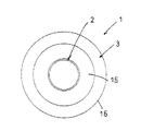
図15及び図16は、本発明に係る容器カバー1の第9実施形態を示している。
この第9実施形態は、上記第7及び第8実施形態の場合と同様に、噴出操作部2による内容物の取出形態がムースタイプとされたもので、上記第7及び第8実施形態と異なるところは、外固定枠14のまわりに肩カバー部16が無い点にある。
この第9実施形態におけるその他の事情は、全て上記第7及び第8実施形態の場合と同じである。
【0037】
図17は、本発明に係る容器カバー1の第10実施形態を示している。
この第10実施形態において、第1実施形態と異なるところは、以下の通りである。すなわち、第1実施形態では、図4に示すように、内外の係合凸条17,18は周方向にオーバーラップしており、カバー体3は、内外固定枠13,14の共同として、マウンテンキャップ12に完全に全周的に係合しているのに対して、第10実施形態では、内外の係合凸条17,18は、周方向に間隔(非オーバーラップ部)dをおいて配置されており、内外固定枠13,14とマウンテンキャップ12との係合は、完全ではないが、ほぼ全周的なものとなっている。また、言い換えれば、第10実施形態では、内外の切欠20,23(非係合部21,24)が周方向に一部オーバーラップしている。このようなものであっても、本発明の目的を十分に達成することができる。
【0038】
図18は、本発明に係る容器カバー1の第11実施形態を示している。この第11実施形態において、第1実施形態と異なるところは、以下の通りである。すなわち、第1実施形態では、外固定枠14の非係合部21は、切欠20を設けることによって形成されていたが、この第11実施形態では、非係合部21は、マウンテンキャップ12に未当接となる離間部30によって形成されている。この離間部30は、外固定枠14が外径方向に屈曲して形成されたものであって、この屈曲した離間部30では、外側の係合凸条18がマウンテンキャップ12から逃げており未当接となる。
【0039】
なお、図18では、外固定枠14の非係合部21が離間部30によって構成されたものを示したが、内固定枠13の非係合部24も同様に離間部によって構成してもよい。この場合、内固定枠13を内径方向に屈曲して形成すればよい。このように、非係合部21,24としては、固定枠13,14に切欠20,23を設けたものや、係合凸条17,18を除去したものの他、離間部30を設けたものとすることもできる。本発明は、上記各実施形態以外にも、各種の変更等が可能である。
【0040】
【発明の効果】
以上の説明から明らかなように、本発明に係る容器カバーにおいてカバー本体は、容器のマウンテンキャップに内嵌及び外嵌する内外二重の固定枠を有し、これら両固定枠にはステム位置を介した対称配置に非係合部が設けられ、そして外固定枠の非係合部位置では内固定枠がマウンテンキャップに係合し、また内固定枠の非係合部位置では外固定枠がマウンテンキャップに係合するようになっている。
【0041】
そのため、廃棄時等の必要時には外固定枠の非係合部位置に対応して側面押圧すれば、容器カバーを容器から簡単に取り外すことができるものであり、必要時以外では(意欲をもって外そうとしない限りは)、内外両固定枠が共同してマウンテンキャップにほぼ全周的に係合しているために、容器から容器カバーが簡単に外れてしまうことはない。
一方、本発明に係る容器カバー付き容器では、上記構成の容器カバーを容器頭部に装着したものであり、上記作用効果を得ることができるものである。
【図面の簡単な説明】
【図1】本発明に係る容器カバーの第1実施形態について容器から取り外す様子を示した側断面図である。
【図2】図3に対応する平面図である。
【図3】本発明に係る容器カバーの第1実施形態を示す側断面図である。
【図4】図3に対応する底面(裏面)図である。
【図5】本発明に係る容器カバーの第2実施形態について図4と比較し易く示した底面(裏面)図である。
【図6】本発明に係る容器カバーの第3実施形態について図4と比較し易く示した底面(裏面)図である。
【図7】本発明に係る容器カバーの第4実施形態について図4と比較し易く示した底面(裏面)図である。
【図8】図9に対応する平面図である。
【図9】本発明に係る容器カバーの第5実施形態を示す側断面図である。
【図10】図11に対応する平面図である。
【図11】本発明に係る容器カバーの第6実施形態を示す側断面図である。
【図12】本発明に係る容器カバーの第7実施形態を示す側断面図である。
【図13】図12に対応する底面(裏面)図である。
【図14】本発明に係る容器カバーの第8実施形態について図13と比較し易く示した底面(裏面)図である。
【図15】本発明に係る容器カバーの第9実施形態を示す側断面図である。
【図16】図15に対応する底面(裏面)図である。
【図17】本発明に係る容器カバーの第10実施形態について図4と比較し易く示した底面(裏面)図である。
【図18】本発明に係る容器カバーの第11実施形態について図4と比較し易く示した底面(裏面)図である。
【符号の説明】
1 容器カバー
2 噴出操作部
3 カバー本体
5 容器
5a 頭部
6 ステム
12 マウンテンキャップ
13 内固定枠
14 外固定枠
15 天枠
16 肩カバー部
20 切欠(外固定枠の非係合部)
21 外固定枠の非係合部
23 切欠(内固定枠の非係合部)
24 内固定枠の非係合部
25 表示部
26 表示部[0001]
BACKGROUND OF THE INVENTION
The present invention relates to a container cover and a container with a container cover.
[0002]
[Prior art]
In containers such as cosmetics and aerosol containers filled with various drugs, solutions, etc., a container cover having a function of taking out contents is mounted on the head.
The container cover includes an ejection operation unit that is fitted to a content extraction stem provided on the container head, and a cover body that covers the head of the container except for the ejection operation unit. It has the structure which it had, and it is divided roughly into a mousse type and a spray type as the extraction form of the content by the ejection operation part.
[0003]
In addition, when the ejection operation part and the cover main body are integrally formed with each other, are separate members, but are inseparably assembled, and the separate members are assembled to the container separately and independently. There is a case.
Such container covers are generally made of plastic, whereas the containers are made of metal such as aluminum or steel, or made of glass. Therefore, in recent years when environmental problems are screamed, the user is required to separate these container covers and containers at the time of disposal after use.
[0004]
By the way, an annular mountain cap is provided at the head of the container so as to surround the stem, and the container cover has a cylindrical fixing frame that engages with the mountain cap while being externally fitted. It is to be attached to the container via a fixed frame.
Conventionally, in order to be able to remove the container cover attached to the container with such a structure at the time of disposal, a notch is provided in the circumferential direction part of the fixed frame from the beginning, and this notch is supported. A structure has been adopted in which a display portion is provided on the outer peripheral surface position or the top surface to urge the notches to be laterally pressed toward the stem position (Japanese Patent Laid-Open Nos. 10-17040 and 10-167356). JP, 10-230197, A JP, 10-245082, etc.).
[0005]
[Problems to be solved by the invention]
In the above-described structure, which has been conventionally used for removing the container cover from the container, a notch is provided in a part of the circumferential direction of the fixed frame. It will not be forgotten.
Therefore, this makes it easy to remove the container cover when necessary, but if you turn it over, this notch will make it easier to remove the container cover even when it is not intended (when not discarding). However, the container cover may come off from the container in spite of the general handling of the container.
[0006]
The present invention has been made in view of the above circumstances, and allows the container cover to be easily removed from the container when necessary, such as during disposal, but the container cover can be easily detached from the container except when necessary. It is an object of the present invention to provide a container cover and a container with a container cover that can prevent such a situation.
[0007]
[Means for Solving the Problems]
In the present invention, in order to achieve the above object, the following technical means are taken.
That is, the container cover according to the present invention is attached to the head of a container provided with a content take-out stem and an annular mountain cap surrounding the stem, and is a jet fitted to the stem. An operation unit and a cover body that covers the head of the container except for the ejection operation unit are provided.
Of these, the cover main body connects the inner fixed frame that can be engaged with the mountain cap by being fitted inside, the outer fixed frame that can be fitted by being fitted to the mountain cap, and the inner and outer fixed frames. And a top frame. That is, it has at least a double fixed frame of an inner fixed frame and an outer fixed frame.
[0008]
Further, the outer fixing frame is provided with a non-engaging portion with respect to the mountain cap at least at one place in the circumferential direction, and the inner fixing frame has a stem position from the non-engaging portion of the outer fixing frame. A non-engaging portion for the mountain cap is provided at a symmetrical position.
In this case, in the outer fixing frame, it is important that the outer fixing frame is ensured to be engageable with the mountain cap at a portion substantially corresponding to the non-engaging portion of the inner fixing frame. Further, in the inner fixing frame, it is important that the inner fixing frame is ensured to be engageable with the mountain cap at a portion substantially corresponding to the non-engaging portion of the outer fixing frame.
[0009]
In such a configuration, the inner fixing frame is engaged with the mountain cap in the portion where the non-engaging portion is provided in the outer fixing frame, and the portion where the non-engaging portion is provided in the inner fixing frame. Since the outer fixing frame is engaged with the mountain cap, as a result, the outer cap is engaged with the mountain cap almost entirely as a joint body of the outer fixing frame and the inner fixing frame.
Therefore, the container cover can be easily removed from the container by pressing the side surface corresponding to the position where the non-engaging portion is provided in the outer fixing frame when necessary, such as at the time of disposal. Unless you are willing to remove it), the container cover will not be removed from the container, or it will be difficult to remove.
[0010]
The cover main body is preferably provided with a display portion for urging the side press corresponding to the circumferential position where the non-engaging portion of the outer fixing frame is provided.
This makes it easier to find the operation position.
The non-engaging portion of the inner fixing frame is preferably formed as a notch that is not in contact with the mountain cap.
This makes it easier to remove.
If the shoulder cover portion that covers the outer fixing frame is provided on the cover body, the non-engaging portion of the outer fixing frame is formed as a notch that is not in contact with the mountain cap. Is preferred.
[0011]
This makes it easier to remove.
A plurality of non-engaging portions of the outer fixing frame and non-engaging portions of the inner fixing frame can be provided in the circumferential direction.
If it does in this way, it will lead to saying that an operation position is easy to find with the increase in an operation position, and it will be easy to remove as a result. Moreover, since it leads to an increase in flexibility in the outer fixed frame and the inner fixed frame, this also promotes ease of removal.
[0012]
On the other hand, in the container with a container cover according to the present invention, the container cover having the above-described configuration is mounted on the container head, and the above-described effects can be obtained.
[0013]
DETAILED DESCRIPTION OF THE INVENTION
Hereinafter, embodiments of the present invention will be described with reference to the drawings.
1 to 4 show a first embodiment of a
As shown in FIGS. 2 and 3, the
[0014]
In this 1st Embodiment, the taking-out form of the content in the
Around the base part of the
[0015]
Accordingly, the connecting
The
[0016]
The
The
[0017]
The
The
[0018]
As shown in FIGS. 3 and 4, the
Similarly, the
[0019]
The
In the
[0020]
That is, the
In addition, when the double structure is formed by the inner and outer fixed
[0021]
As shown in FIG. 2, the top surface of the
The
[0022]
Further, it is sufficient to provide only one of the two
Assuming that the
In order to remove the
[0023]
Then, the
Therefore, the inner fixed
[0024]
On the other hand, the
For this reason, the
On the other hand, when the
[0025]
Then, a force for laterally moving is directly applied to the
[0026]
For this reason, the
FIG. 5 shows a second embodiment of the
In the second embodiment, the difference from the first embodiment is that the
[0027]
The
[0028]
The
About another structure and an effect, it is substantially the same as the case of the said 1st Embodiment.
FIG. 7 shows a fourth embodiment of the
In the fourth embodiment, the difference from the first embodiment is that the
[0029]
In this 4th Embodiment, the operation position which enables a side surface press with respect to the
Further, when the operation position is set to Ya, Yb, Yc as shown in FIG. 7, as a structure for receiving a pressing operation to the Ya position, as in the case of the first embodiment, the non-engaging portion of the
[0030]
Further, even in the structure for receiving the pressing operation to the Yc position, the
Even in such a configuration, the same effects as those in the first embodiment can be obtained.
8 and 9 show a fifth embodiment of the
[0031]
In the fifth embodiment, the content extraction form by the
Further, the
Accordingly, also in the fifth embodiment, similarly to the first embodiment described above, not only the portion indicated by the arrow Y in FIG. 9 but also the portion indicated by the arrow X, that is, the side surface of the
[0032]
About another structure and an effect, it is substantially the same as the case of the said 1st Embodiment. Various different configurations from the first embodiment described in the second to fourth embodiments can also be adopted in the fifth embodiment.
10 and 11 show a sixth embodiment of the
In the sixth embodiment as well, the content extraction form by the
[0033]
However, since the ejecting
[0034]
12 and 13 show a seventh embodiment of the
As in the case of the first embodiment, the seventh embodiment is such that the content extraction form by the
Therefore, in the case of such a
[0035]
Further, in the seventh embodiment, the
In addition, also about this 7th Embodiment, various different structures from 1st Embodiment demonstrated in 2nd thru | or 4th embodiment are employable.
In particular, FIG. 14 is an eighth embodiment in the case where the deformation is applied in the same pattern as the development from the first embodiment to the fourth embodiment (see FIG. 7) in the case of being based on the seventh embodiment. However, as is clear from FIG. 14, it is possible to provide a plurality of
[0036]
15 and 16 show a ninth embodiment of the
As in the case of the seventh and eighth embodiments, the ninth embodiment differs from the seventh and eighth embodiments in that the ejection form of the contents by the
The other circumstances in the ninth embodiment are the same as those in the seventh and eighth embodiments.
[0037]
FIG. 17 shows a tenth embodiment of a
The tenth embodiment is different from the first embodiment as follows. That is, in the first embodiment, as shown in FIG. 4, the inner and outer engaging
[0038]
Figure 18 These show 11th Embodiment of the
[0039]
Figure 18 In the above description, the
[0040]
【The invention's effect】
As is clear from the above description, in the container cover according to the present invention, the cover main body has inner and outer double fixing frames that fit inside and outside the mountain cap of the container. A non-engaging portion is provided in a symmetrical arrangement, and the inner fixing frame engages with the mountain cap at the non-engaging portion position of the outer fixing frame, and the outer fixing frame is at the non-engaging portion position of the inner fixing frame. It is designed to engage with a mountain cap.
[0041]
Therefore, the container cover can be easily removed from the container by pressing the side surface corresponding to the position of the non-engaging portion of the outer fixing frame when necessary, such as during disposal. The inner and outer fixed frames jointly engage the mountain cap almost entirely, so that the container cover is not easily removed from the container.
On the other hand, in the container with a container cover according to the present invention, the container cover having the above-described configuration is mounted on the container head, and the above-described effects can be obtained.
[Brief description of the drawings]
FIG. 1 is a side sectional view showing a state in which a container cover according to a first embodiment of the present invention is removed from a container.
FIG. 2 is a plan view corresponding to FIG. 3;
FIG. 3 is a sectional side view showing a first embodiment of a container cover according to the present invention.
4 is a bottom (back) view corresponding to FIG. 3; FIG.
FIG. 5 is a bottom (rear) view showing a container cover according to a second embodiment of the present invention in a manner easier to compare with FIG.
6 is a bottom (rear) view of a third embodiment of a container cover according to the present invention, which is easy to compare with FIG. 4. FIG.
FIG. 7 is a bottom (rear) view showing a container cover according to a fourth embodiment of the present invention in a manner easier to compare with FIG.
FIG. 8 is a plan view corresponding to FIG. 9;
FIG. 9 is a side sectional view showing a fifth embodiment of a container cover according to the present invention.
10 is a plan view corresponding to FIG. 11. FIG.
FIG. 11 is a side sectional view showing a sixth embodiment of a container cover according to the present invention.
FIG. 12 is a side sectional view showing a seventh embodiment of a container cover according to the present invention.
13 is a bottom (back) view corresponding to FIG. 12; FIG.
FIG. 14 is a bottom (back) view showing an eighth embodiment of a container cover according to the present invention, which can be easily compared with FIG. 13;
FIG. 15 is a side sectional view showing a ninth embodiment of a container cover according to the present invention.
16 is a bottom (back) view corresponding to FIG. 15. FIG.
FIG. 17 is a bottom (rear) view showing a tenth embodiment of a container cover according to the present invention, which is easy to compare with FIG. 4;
18 is a bottom (rear) view showing an eleventh embodiment of a container cover according to the present invention, which can be easily compared with FIG. 4; FIG.
[Explanation of symbols]
1 Container cover
2 Spout operation part
3 Cover body
5 containers
5a head
6 stem
12 Mountain cap
13 Inner fixed frame
14 Outer fixed frame
15 Top frame
16 Shoulder cover
20 Notch (non-engaging part of outer fixed frame)
21 Non-engaging part of outer fixing frame
23 Notch (non-engaging part of the inner fixed frame)
24 Non-engagement part of inner fixed frame
25 Display section
26 Display section
Claims (6)
上記ステム(6)に嵌着されていてステム(6)を押し操作可能な噴出操作部(2)と、該噴出操作部(2)を除いて上記容器(5)の頭部(5a)を被蓋するカバー本体(3)とを有しており、
上記カバー本体(3)は、上記マウンテンキャップ(12)に内嵌して係合可能となる内固定枠(13)と、マウンテンキャップ(12)に外嵌して係合可能となる外固定枠(14)と、これら内外固定枠(13,14)を連結する天枠(15)とを有し、
上記外固定枠(14)には周方向の少なくとも1か所にマウンテンキャップ(12)に対する非係合部(21)が設けられていると共に、上記内固定枠(13)には外固定枠(14)の非係合部(21)からステム(6)位置を介した対称位置にマウンテンキャップ(12)に対する非係合部(24)が設けられており、
外固定枠(14)における内固定枠(13)の非係合部(24)とほぼ対応する部位では当該外固定枠(14)が、また内固定枠(13)における外固定枠(14)の非係合部(21)とほぼ対応する部位では当該内固定枠(13)が、それぞれマウンテンキャップ(12)に係合可能な状態を確保されており、
外固定枠(14)において非係合部(21)が設けられている位置に対応して、この位置で噴出操作部(2)とカバー本体(3)の少なくとも噴出操作部(2)の側面を横押しすることによって噴出操作部(2)とカバー本体(3)とが一体とされてマウンテンキャップ(12)から取り外し可能とされ、
前記噴出操作部(2)の根元部まわりには、連結部(8)を除いて周溝(9)が設けられ、前記噴出操作部(2)及び前記カバー本体(3)は該連結部(8)を介して一体形成されていることを特徴とする容器カバー。In a container cover attached to the head (5a) of a container (5) provided with a stem (6) for taking out contents and an annular mountain cap (12) surrounding the stem (6),
An ejection operation part (2) fitted to the stem (6) and capable of pushing the stem (6) and the head (5a) of the container (5) except for the ejection operation part (2). A cover body (3) to be covered;
The cover body (3) includes an inner fixed frame (13) that can be engaged with the mountain cap (12) and an outer fixed frame that can be engaged with the mountain cap (12). (14) and a top frame (15) for connecting these inner and outer fixed frames (13, 14),
The outer fixed frame (14) is provided with a non-engaging portion (21) with respect to the mountain cap (12) at at least one place in the circumferential direction, and the inner fixed frame (13) has an outer fixed frame ( 14) a non-engaging portion (24) for the mountain cap (12) is provided at a symmetrical position from the non-engaging portion (21) to the stem (6) position,
In the outer fixing frame (14), the outer fixing frame (14) corresponds to the non-engaging portion (24) of the inner fixing frame (13), and the outer fixing frame (14) in the inner fixing frame (13). In the portion substantially corresponding to the non-engaging portion (21), the inner fixing frame (13) is ensured to be engageable with the mountain cap (12),
Corresponding to the position where the non-engaging portion (21) is provided in the outer fixing frame (14), at this position, at least the side surface of the ejection operation portion (2) of the ejection operation portion (2) and the cover body (3). The spray operation part (2) and the cover main body (3) are integrated with each other and can be detached from the mountain cap (12).
A circumferential groove (9) is provided around the base portion of the ejection operation portion (2) except for the connection portion (8), and the ejection operation portion (2) and the cover body (3) are connected to the connection portion ( 8) A container cover characterized by being integrally formed via
上記ステム(6)に嵌着されていてステム(6)を押し操作可能な噴出操作部(2)と、該噴出操作部(2)を除いて上記容器(5)の頭部(5a)を被蓋するカバー本体(3)とを有しており、
上記カバー本体(3)は、上記マウンテンキャップ(12)に内嵌して係合可能となる内固定枠(13)と、マウンテンキャップ(12)に外嵌して係合可能となる外固定枠(14)と、これら内外固定枠(13,14)を連結する天枠(15)とを有し、
上記外固定枠(14)には周方向の少なくとも1か所にマウンテンキャップ(12)に対する非係合部(21)が設けられていると共に、上記内固定枠(13)には外固定枠(14)の非係合部(21)からステム(6)位置を介した対称位置にマウンテンキャップ(12)に対する非係合部(24)が設けられており、
外固定枠(14)における内固定枠(13)の非係合部(24)とほぼ対応する部位では当該外固定枠(14)が、また内固定枠(13)における外固定枠(14)の非係合部(21)とほぼ対応する部位では当該内固定枠(13)が、それぞれマウンテンキャップ(12)に係合可能な状態を確保されており、
外固定枠(14)において非係合部(21)が設けられている位置に対応して、この位置で噴出操作部(2)とカバー本体(3)の内の少なくとも噴出操作部(2)の側面を横押しすることによって噴出操作部(2)とカバー本体(3)とが一体とされてマウンテンキャップ(12)から取り外し可能とされ、
前記噴出操作部(2)とカバー本体(3)とは別部材で形成されかつカバー本体(3)に対して抜止めのための係合鍔(33)が設けられていることを特徴とする容器カバー。 In a container cover attached to the head (5a) of a container (5) provided with a stem (6) for taking out contents and an annular mountain cap (12) surrounding the stem (6),
An ejection operation part (2) fitted to the stem (6) and capable of pushing the stem (6) and the head (5a) of the container (5) except for the ejection operation part (2). A cover body (3) to be covered;
The cover body (3) includes an inner fixed frame (13) that can be engaged with the mountain cap (12) and an outer fixed frame that can be engaged with the mountain cap (12). (14) and a top frame (15) for connecting these inner and outer fixed frames (13, 14),
The outer fixed frame (14) is provided with a non-engaging portion (21) with respect to the mountain cap (12) at at least one place in the circumferential direction, and the inner fixed frame (13) has an outer fixed frame ( 14) a non-engaging portion (24) for the mountain cap (12) is provided at a symmetrical position from the non-engaging portion (21) to the stem (6) position,
In the outer fixing frame (14), the outer fixing frame (14) corresponds to the non-engaging portion (24) of the inner fixing frame (13), and the outer fixing frame (14) in the inner fixing frame (13). In the portion substantially corresponding to the non-engaging portion (21), the inner fixing frame (13) is ensured to be engageable with the mountain cap (12),
Corresponding to the position where the non-engaging portion (21) is provided in the outer fixed frame (14), at least the ejection operation portion (2) of the ejection operation portion (2) and the cover body (3) at this position. By side-pressing the side of the squirting unit, the ejection operation part (2) and the cover main body (3) are integrated and removable from the mountain cap (12).
And wherein the engagement flange for retaining (33) are found provided for and the cover body is formed of a separate member (3) is the jet operating portion (2) and the cover body (3) container cover you.
Priority Applications (1)
| Application Number | Priority Date | Filing Date | Title |
|---|---|---|---|
| JP22256799A JP3805930B2 (en) | 1999-08-05 | 1999-08-05 | Container cover and container with container cover |
Applications Claiming Priority (1)
| Application Number | Priority Date | Filing Date | Title |
|---|---|---|---|
| JP22256799A JP3805930B2 (en) | 1999-08-05 | 1999-08-05 | Container cover and container with container cover |
Publications (2)
| Publication Number | Publication Date |
|---|---|
| JP2001048256A JP2001048256A (en) | 2001-02-20 |
| JP3805930B2 true JP3805930B2 (en) | 2006-08-09 |
Family
ID=16784494
Family Applications (1)
| Application Number | Title | Priority Date | Filing Date |
|---|---|---|---|
| JP22256799A Expired - Fee Related JP3805930B2 (en) | 1999-08-05 | 1999-08-05 | Container cover and container with container cover |
Country Status (1)
| Country | Link |
|---|---|
| JP (1) | JP3805930B2 (en) |
Families Citing this family (1)
| Publication number | Priority date | Publication date | Assignee | Title |
|---|---|---|---|---|
| JP7239278B2 (en) * | 2018-06-18 | 2023-03-14 | 東洋エアゾール工業株式会社 | BUTTON, BUTTON MOUNTING METHOD, AND BUTTON MOUNTING DEVICE |
-
1999
- 1999-08-05 JP JP22256799A patent/JP3805930B2/en not_active Expired - Fee Related
Also Published As
| Publication number | Publication date |
|---|---|
| JP2001048256A (en) | 2001-02-20 |
Similar Documents
| Publication | Publication Date | Title |
|---|---|---|
| US20140166659A1 (en) | Package formed by container and overcap | |
| JP4786236B2 (en) | Cap with excellent separation and disposal | |
| JP3231019B2 (en) | Plastic container cover | |
| JP4999756B2 (en) | container | |
| JP3805930B2 (en) | Container cover and container with container cover | |
| EP1616801B1 (en) | Cup shaped container | |
| JP4473361B2 (en) | Fitting structure between overcap, shoulder cover and aerosol container | |
| JP5362457B2 (en) | Hinge cap with excellent separation and disposal | |
| JP4330234B2 (en) | Container and its cap | |
| JP4420301B2 (en) | Plastic cap with stopper mounting type | |
| JP2005047515A (en) | Can container with overcap | |
| JP3688468B2 (en) | Aerosol container | |
| JP4331450B2 (en) | Container mounting cover body and aerosol type product and pump type product provided with the same | |
| US20050115916A1 (en) | Crown cap | |
| JP4514092B2 (en) | Plastic overcap | |
| JP2017132510A (en) | Plug driving type resin cap | |
| JP4172873B2 (en) | Can container with cap for resealing | |
| JP4684091B2 (en) | Aerosol container cap | |
| JP3908417B2 (en) | Can with temporary sealing stopper | |
| JP3970443B2 (en) | Spray container and container cover body | |
| JP3876040B2 (en) | Cap for aerosol can | |
| JP2004315011A (en) | Cap for aerosol container | |
| JP3753807B2 (en) | Container with lid | |
| JPH07329995A (en) | Laminate tube container | |
| JP3776623B2 (en) | Can with temporary sealing stopper |
Legal Events
| Date | Code | Title | Description |
|---|---|---|---|
| A977 | Report on retrieval |
Free format text: JAPANESE INTERMEDIATE CODE: A971007 Effective date: 20050531 |
|
| A131 | Notification of reasons for refusal |
Free format text: JAPANESE INTERMEDIATE CODE: A131 Effective date: 20050607 |
|
| A521 | Written amendment |
Free format text: JAPANESE INTERMEDIATE CODE: A523 Effective date: 20050802 |
|
| TRDD | Decision of grant or rejection written | ||
| A01 | Written decision to grant a patent or to grant a registration (utility model) |
Free format text: JAPANESE INTERMEDIATE CODE: A01 Effective date: 20060509 |
|
| A61 | First payment of annual fees (during grant procedure) |
Free format text: JAPANESE INTERMEDIATE CODE: A61 Effective date: 20060511 |
|
| R150 | Certificate of patent or registration of utility model |
Free format text: JAPANESE INTERMEDIATE CODE: R150 |
|
| FPAY | Renewal fee payment (event date is renewal date of database) |
Free format text: PAYMENT UNTIL: 20100519 Year of fee payment: 4 |
|
| FPAY | Renewal fee payment (event date is renewal date of database) |
Free format text: PAYMENT UNTIL: 20110519 Year of fee payment: 5 |
|
| FPAY | Renewal fee payment (event date is renewal date of database) |
Free format text: PAYMENT UNTIL: 20110519 Year of fee payment: 5 |
|
| FPAY | Renewal fee payment (event date is renewal date of database) |
Free format text: PAYMENT UNTIL: 20120519 Year of fee payment: 6 |
|
| FPAY | Renewal fee payment (event date is renewal date of database) |
Free format text: PAYMENT UNTIL: 20130519 Year of fee payment: 7 |
|
| FPAY | Renewal fee payment (event date is renewal date of database) |
Free format text: PAYMENT UNTIL: 20130519 Year of fee payment: 7 |
|
| R250 | Receipt of annual fees |
Free format text: JAPANESE INTERMEDIATE CODE: R250 |
|
| R250 | Receipt of annual fees |
Free format text: JAPANESE INTERMEDIATE CODE: R250 |
|
| LAPS | Cancellation because of no payment of annual fees |