JP3799770B2 - Catalyst deterioration diagnosis device for internal combustion engine - Google Patents
Catalyst deterioration diagnosis device for internal combustion engine Download PDFInfo
- Publication number
- JP3799770B2 JP3799770B2 JP25369197A JP25369197A JP3799770B2 JP 3799770 B2 JP3799770 B2 JP 3799770B2 JP 25369197 A JP25369197 A JP 25369197A JP 25369197 A JP25369197 A JP 25369197A JP 3799770 B2 JP3799770 B2 JP 3799770B2
- Authority
- JP
- Japan
- Prior art keywords
- catalyst
- concentration
- injection
- reducing agent
- supplied
- Prior art date
- Legal status (The legal status is an assumption and is not a legal conclusion. Google has not performed a legal analysis and makes no representation as to the accuracy of the status listed.)
- Expired - Fee Related
Links
Images


Classifications
-
- F—MECHANICAL ENGINEERING; LIGHTING; HEATING; WEAPONS; BLASTING
- F02—COMBUSTION ENGINES; HOT-GAS OR COMBUSTION-PRODUCT ENGINE PLANTS
- F02B—INTERNAL-COMBUSTION PISTON ENGINES; COMBUSTION ENGINES IN GENERAL
- F02B37/00—Engines characterised by provision of pumps driven at least for part of the time by exhaust
-
- F—MECHANICAL ENGINEERING; LIGHTING; HEATING; WEAPONS; BLASTING
- F01—MACHINES OR ENGINES IN GENERAL; ENGINE PLANTS IN GENERAL; STEAM ENGINES
- F01N—GAS-FLOW SILENCERS OR EXHAUST APPARATUS FOR MACHINES OR ENGINES IN GENERAL; GAS-FLOW SILENCERS OR EXHAUST APPARATUS FOR INTERNAL COMBUSTION ENGINES
- F01N11/00—Monitoring or diagnostic devices for exhaust-gas treatment apparatus, e.g. for catalytic activity
-
- F—MECHANICAL ENGINEERING; LIGHTING; HEATING; WEAPONS; BLASTING
- F01—MACHINES OR ENGINES IN GENERAL; ENGINE PLANTS IN GENERAL; STEAM ENGINES
- F01N—GAS-FLOW SILENCERS OR EXHAUST APPARATUS FOR MACHINES OR ENGINES IN GENERAL; GAS-FLOW SILENCERS OR EXHAUST APPARATUS FOR INTERNAL COMBUSTION ENGINES
- F01N2550/00—Monitoring or diagnosing the deterioration of exhaust systems
- F01N2550/02—Catalytic activity of catalytic converters
-
- F—MECHANICAL ENGINEERING; LIGHTING; HEATING; WEAPONS; BLASTING
- F02—COMBUSTION ENGINES; HOT-GAS OR COMBUSTION-PRODUCT ENGINE PLANTS
- F02M—SUPPLYING COMBUSTION ENGINES IN GENERAL WITH COMBUSTIBLE MIXTURES OR CONSTITUENTS THEREOF
- F02M26/00—Engine-pertinent apparatus for adding exhaust gases to combustion-air, main fuel or fuel-air mixture, e.g. by exhaust gas recirculation [EGR] systems
- F02M26/02—EGR systems specially adapted for supercharged engines
- F02M26/04—EGR systems specially adapted for supercharged engines with a single turbocharger
- F02M26/05—High pressure loops, i.e. wherein recirculated exhaust gas is taken out from the exhaust system upstream of the turbine and reintroduced into the intake system downstream of the compressor
-
- F—MECHANICAL ENGINEERING; LIGHTING; HEATING; WEAPONS; BLASTING
- F02—COMBUSTION ENGINES; HOT-GAS OR COMBUSTION-PRODUCT ENGINE PLANTS
- F02M—SUPPLYING COMBUSTION ENGINES IN GENERAL WITH COMBUSTIBLE MIXTURES OR CONSTITUENTS THEREOF
- F02M26/00—Engine-pertinent apparatus for adding exhaust gases to combustion-air, main fuel or fuel-air mixture, e.g. by exhaust gas recirculation [EGR] systems
- F02M26/13—Arrangement or layout of EGR passages, e.g. in relation to specific engine parts or for incorporation of accessories
- F02M26/42—Arrangement or layout of EGR passages, e.g. in relation to specific engine parts or for incorporation of accessories having two or more EGR passages; EGR systems specially adapted for engines having two or more cylinders
-
- Y—GENERAL TAGGING OF NEW TECHNOLOGICAL DEVELOPMENTS; GENERAL TAGGING OF CROSS-SECTIONAL TECHNOLOGIES SPANNING OVER SEVERAL SECTIONS OF THE IPC; TECHNICAL SUBJECTS COVERED BY FORMER USPC CROSS-REFERENCE ART COLLECTIONS [XRACs] AND DIGESTS
- Y02—TECHNOLOGIES OR APPLICATIONS FOR MITIGATION OR ADAPTATION AGAINST CLIMATE CHANGE
- Y02T—CLIMATE CHANGE MITIGATION TECHNOLOGIES RELATED TO TRANSPORTATION
- Y02T10/00—Road transport of goods or passengers
- Y02T10/10—Internal combustion engine [ICE] based vehicles
- Y02T10/12—Improving ICE efficiencies
-
- Y—GENERAL TAGGING OF NEW TECHNOLOGICAL DEVELOPMENTS; GENERAL TAGGING OF CROSS-SECTIONAL TECHNOLOGIES SPANNING OVER SEVERAL SECTIONS OF THE IPC; TECHNICAL SUBJECTS COVERED BY FORMER USPC CROSS-REFERENCE ART COLLECTIONS [XRACs] AND DIGESTS
- Y02—TECHNOLOGIES OR APPLICATIONS FOR MITIGATION OR ADAPTATION AGAINST CLIMATE CHANGE
- Y02T—CLIMATE CHANGE MITIGATION TECHNOLOGIES RELATED TO TRANSPORTATION
- Y02T10/00—Road transport of goods or passengers
- Y02T10/10—Internal combustion engine [ICE] based vehicles
- Y02T10/40—Engine management systems
Landscapes
- Engineering & Computer Science (AREA)
- Chemical & Material Sciences (AREA)
- Combustion & Propulsion (AREA)
- Mechanical Engineering (AREA)
- General Engineering & Computer Science (AREA)
- Chemical Kinetics & Catalysis (AREA)
- Exhaust Gas After Treatment (AREA)
Description
【0001】
【発明の属する技術分野】
本発明は多気筒内燃機関の排気浄化装置に関する。
【0002】
【従来の技術】
内燃機関から排出される窒素酸化物(以下、NOX )を浄化するための排気浄化装置が公知である。例えば、特開平7−54641号公報にはNOX を浄化するために、排気ガス中の酸素濃度が非常に高い状態において、炭化水素(以下、HC)を触媒表面に吸着させてHCの活性種を生成し、このHCの活性種とNOX とを反応させることによりNOX を浄化するNOX 選択還元触媒(以下、NOX 触媒)を具備する排気浄化装置が開示されている。
通常、NOX 触媒を備えた排気浄化装置では、酸素を多量に含んだ排気ガス中にはHCがほとんど含まれていないため、別途、HCを触媒に供給している。
また、上記排気浄化装置ではNOX 触媒の上流側と下流側とにおける排気ガス中のNOX 濃度を検出し、これら触媒上流側NOX 濃度と触媒下流側NOX 濃度とに基づきNOX 浄化率を算出し、このNOX 浄化率が予め定められた浄化率以下となったときにNOX 触媒が劣化したと判定している。
【0003】
【発明が解決しようとする課題】
ところで内燃機関では機関駆動用に気筒内に噴射されたHCが機関燃焼時に完全に燃焼せずに残ることがある。したがって排気ガスによりNOX 触媒に到達せしめられた残余HCによりNOX が浄化されることがある。このため、HCが別途供給されるまえに残余HCによりNOX が浄化されているので、NOX 浄化率が予め定められた浄化率より高くても実際には触媒が劣化していることがある。すなわち上記排気浄化装置では正確に触媒の劣化を診断することができない。したがって本発明の目的は機関駆動用に供給されたが燃焼せずに残るHC量にかかわらず、正確に触媒劣化を診断することにある。
【0004】
【課題を解決するための手段】
上記課題を解決するために一番目の発明によれば、排気通路に配置された触媒と、該触媒に還元剤を供給する還元剤供給手段と、前記触媒下流におけるNOX 濃度を検出するNOX 濃度検出手段とを具備する内燃機関の触媒劣化診断装置であって、前記NOX 濃度検出手段が前記還元剤供給手段により還元剤が供給されたときの還元剤供給時NOX 濃度と還元剤が供給されていないときの還元剤非供給時NOX 濃度とを検出し、これらNOX 濃度に基づいて触媒の劣化を診断する内燃機関の触媒劣化診断装置において、前記NO X 濃度検出手段は還元剤の供給が停止されてから予め定められた時間が経過したときに前記還元剤非供給時NO X 濃度を検出し、該予め定められた時間は触媒温度が高いほど短い。
【0005】
上記課題を解決するために二番目の発明によれば、一番目の発明において、前記NOX 濃度検出手段は機関運転状態が定常運転状態であるときに前記還元剤供給時NOX 濃度および還元剤非供給時NOX 濃度を検出する。これによれば略等しい機関運転状態において還元剤供給時NOX 濃度および還元剤非供給時NOX 濃度が検出される。
【0007】
【発明の実施の形態】
図1は本発明の実施形態の内燃機関の排気浄化装置の構成を示す図である。図1において、1は機関本体、♯1、♯2、♯3および♯4はそれぞれ機関本体1内に形成された第一気筒、第二気筒、第三気筒および第四気筒、2a、2b、2cおよび2dはそれぞれ対応する気筒♯1〜♯4内に機関駆動用燃料および排気ガス浄化用燃料を供給するための第一燃料噴射弁、第二燃料噴射弁、第三燃料噴射弁および第四燃料噴射弁、3は機関本体1に接続された吸気通路、4は吸気通路3に接続されたインテークマニホルドである。インテークマニホルド4には吸入空気量を算出するために吸入空気圧を検出する吸気圧センサ5が取り付けられる。また、本発明の内燃機関はクランク角を検出するクランク角センサ6を具備する。各燃料噴射弁2a〜2dはこれら燃料噴射弁2a〜2dに共通の燃料分配手段、すなわちコモンレール30に接続される。コモンレール30はポンプPを介して燃料タンク31に接続される。コモンレール30内には燃料タンク31により予め定められた圧力に加圧された燃料が蓄積される。また、コモンレール30にはコモンレール30内の燃料の圧力を検出するための圧力検出手段として燃圧センサ32が取り付けられる。
【0008】
第一気筒♯1、第二気筒♯2、第三気筒♯3および第四気筒♯4にはそれぞれ対応して第一排気枝管7a、第二排気枝管7b、第三排気枝管7cおよび第四排気枝管7dが接続される。第一排気枝管7aと第二排気枝管7bと第四排気枝管7dとは機関本体1の下流側の上流側合流部8において合流せしめられ、集合管9に接続される。集合管9と第三排気枝管7cとは上流側合流部8のさらに下流側の下流側合流部10において合流せしめられる。なお、本明細書において『上流』および『下流』とは排気ガスの流れに沿った方向について用いられる用語である。
【0009】
本発明の内燃機関は吸入される空気量を増大するために吸入空気を過給する過給機11を具備する。過給機11はインテークマニホルド4の上流側の吸気通路3に配置された吸気側タービンホイール11aと、下流側合流部10の下流側の排気通路20内に配置された排気側タービンホイール11bとを具備する。本発明では各気筒から排出された排気ガスが合流する位置に排気側タービンホイール11bが配置されているため、排気側タービンホイール11bを通過する排気ガス量が多く、過給機11の過給効果を最大限に維持することができる。
【0010】
吸気側タービンホイール11aと排気側タービンホイール11bとは一つのシャフト11cにより互いに連結される。排気側タービンホイール11bはこの排気側タービンホイール11bの回転面と平行な方向から排気ガスを受けて回転せしめられ、回転面に対して垂直な方向へ向けて排気ガスを排出する。一方、吸気側タービンホイール11aは排気側タービンホイール11bの回転に伴い回転せしめられ、この吸気側タービンホイール11aの回転面に対して垂直な方向から空気を引き込み、回転面と平行な方向へ向けて吸入空気を送りだす。
【0011】
排気側タービンホイール11bの下流側の排気通路20には内燃機関から排出される窒素酸化物(以下、NOX )を浄化するための排気浄化触媒12が配置される。本発明の排気浄化触媒12は、機関内で燃焼せしめられる混合気の空燃比が理論空燃比より非常に大きいために排気ガス中の酸素濃度が非常に高い状態において、炭化水素(以下、HC)を触媒表面に吸着させてHCの活性種を生成し、このHCの活性種とNOX とを反応させることによりNOX を浄化するNOX 選択還元触媒(以下、NOX 触媒)である。NOX 触媒12の上流端部分には該上流端部分の温度を検出する上流側温度センサ13が配置され、NOX 触媒12の下流端部分には該下流側部分の温度を検出する下流側温度センサ14が配置される。さらにNOX 触媒12の上流側の排気通路20にはNOX 触媒12の上流側における排気ガス中のNOX 濃度を検出する上流側NOX 濃度センサ33が配置され、NOX 触媒12の下流側の排気通路20にはNOX 触媒12の下流側における排気ガス中のNOX 濃度を検出する下流側NOX 濃度センサ34が配置される。
【0012】
第四排気枝管7dには排気ガスを吸入空気中に導入するための排気循環管15が接続される。排気循環管15の他端はインテークマニホルド4に接続される。排気循環管15には吸入空気中への排気ガスの導入の有無を制御するための排気循環弁16が配置される。排気循環弁16は三方弁17を介して吸引ポンプ18および大気に連通される。排気循環弁16は機関運転状態に応じて開閉制御される。三方弁17により排気循環弁16と大気とが連通せしめられると排気循環弁16内に大気圧がかかり排気循環弁16は閉弁せしめられる。一方、三方弁17により排気循環弁16と吸引ポンプ18とが連通せしめられると排気循環弁16内に負圧がかかり排気循環弁16が開弁せしめられる。これにより排気ガスが吸入空気中に導入される。内燃機関において生成されるNOX 量は燃焼時の火炎伝播速度が大きいほど多くなる。また、NOX 生成量は燃焼時の燃焼温度が高いほど多くなる。一方、不活性ガスは燃焼時の火炎伝播を緩慢にするため、燃焼時の火炎伝播速度は吸入空気中の不活性ガス量が多いほど小さくなる。また、不活性ガスは燃焼時の熱を吸収するため、燃焼時の燃焼温度は吸入空気中の不活性ガス量が多いほど低くなる。したがって不活性ガスであるCO2 やH2 Oを含んだ排気ガスが吸入空気に導入されると、燃焼時の火炎伝播速度が小さくなり且つ燃焼時の燃焼温度が低く抑制されるため、燃焼に伴うNOX の生成が抑制される。
【0013】
図1において制御装置(ECU)40はデジタルコンピュータからなり、双方向性バス41を介して相互に接続されたCPU(マイクロプロセッサ)42、ROM(リードオンリーメモリ)43、RAM(ランダムアクセスメモリ)44、B−RAM(バックアップRAM)45、入力ポート46、出力ポート47およびクロック発生器48を具備する。吸気圧センサ5、上流側温度センサ13、下流側温度センサ14、燃圧センサ32、上流側NOX 濃度センサ33および下流側NOX 濃度センサ34の出力電圧はそれぞれ対応するAD変換器49を介して入力ポート46に入力される。また、クランク角センサ6の出力電圧は直接入力ポート46に入力される。一方、出力ポート47はそれぞれ対応する駆動回路50を介して各燃料噴射弁2a〜2d、三方弁17および警報装置35に接続される。
【0014】
次に本実施形態の内燃機関の作動について説明する。初めに各気筒♯1〜♯4の圧縮行程の予め定められたクランク角度においてコモンレール30内の燃圧が燃圧センサ32により検出される。次に各気筒♯1〜♯4の圧縮上死点の直前において予噴射が実行され、予め定められた量の燃料が各燃料噴射弁2a〜2dから噴射される。予噴射は気筒内において生成されるNOX 量の低減および気筒において生じる騒音の低減のために実行される噴射である。
【0015】
次に予噴射により供給された燃料が筒内において着火した後の圧縮上死点付近の予め定められたクランク角度において主噴射が実行される。主噴射は機関駆動のために実行される噴射である。各燃料噴射弁2a〜2dから主噴射により噴射すべき主噴射燃料量はアクセルペダル(図示せず)の踏込量に基づいて決定される。なお、予噴射および主噴射により各燃料噴射弁2a〜2dから噴射すべき予噴射燃料量および主噴射燃料量を供給するために各燃料噴射弁2a〜2dを開弁する開弁時間はコモンレール30内の燃圧に基づいて決定される。また、各気筒における予噴射および主噴射は第一気筒♯1、第三気筒♯3、第四気筒♯4、第二気筒♯2の順で実行される。
【0016】
さらに本実施形態では第三気筒♯3において主噴射が実行された後に該主噴射とは別個に副噴射を実行し、NOX 触媒12にNOX 浄化用のHCを供給する。なお、NOX 触媒12に供給すべき副噴射燃料量、すなわち浄化用HC量は吸気圧センサ5およびクランク角センサ6の出力から推定した機関からのNOX 排出量と、上流側温度センサ13および下流側温度センサ14の出力とに基づいて決定される。また、副噴射の実行時期は上流側温度センサ13の出力から推定した第三気筒♯3内の温度およびコモンレール30内の燃圧に基づいて決定される。さらに、副噴射により第三燃料噴射弁2cから噴射すべき副噴射燃料量を供給するために第三燃料噴射弁2cを開弁する開弁時間はコモンレール30内の燃圧に基づいて決定される。
【0017】
次に図2のフローチャートを参照して本実施形態の予噴射・主噴射実行制御を説明する。なお、図2のフローチャートにおいてnは気筒番号を示し、1、3、4、2の順で変化する。まず、ステップS110において現在のクランク角度CAが第n気筒において予噴射を実行すべき予め定められた予噴射クランク角度PCApnである(CA=PCApn)か否かが判別される。ステップS110においてCA=PCApnである判別されると、ステップS112に進んで予め定められた予噴射用開弁時間tpnだけ第n気筒の燃料噴射弁を開弁して予噴射を実行し、ステップS114に進む。一方、ステップS110においてCA≠PCApnであると判別されると、CA=PCApnと判別されるまでステップS110が繰り返される。
【0018】
ステップS114では現在のクランク角度CAが第n気筒において主噴射を実行すべき予め定められた主噴射クランク角度PCAmnである(CA=PCAmn)か否かが判別される。ステップS114においてCA=PCAmnである判別されると、ステップS116に進んで予め定められた主噴射用開弁時間tmnだけ第n気筒の燃料噴射弁を開弁して主噴射を実行し、処理を終了する。一方、ステップS114においてCA≠PCAmnであると判別されると、CA=PCAmnと判別されるまでステップS114が繰り返される。
【0019】
次に図3のフローチャートを参照して本実施形態の主噴射燃料量算出制御を説明する。なお、図3のフローチャートにおいてnは気筒番号を示し、1、3、4、2の順で変化する。まず、ステップS210においてアクセルペダルの踏込量Daが読み込まれる。次にステップS212に進んでステップS210において読み込まれたアクセルペダルの踏込量Daに基づいて主噴射により第n気筒内に供給すべき主噴射燃料量を燃料噴射弁から噴射するのに必要な燃料噴射弁の開弁時間tmpnを算出する。次にステップS214に進んでステップS212において算出した開弁時間tmpnを主噴射用開弁時間tmnにセットし、処理を終了する。
【0020】
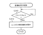
次に図4のフローチャートを参照して本実施形態の副噴射実行制御を説明する。まず、ステップS310において現在のクランク角度CAが第三気筒において副噴射を実行すべき予め定められた副噴射クランク角度CAs3である(CA=CAs3)か否かが判別される。ステップS310においてCA=CAs3である判別されると、ステップS312に進んで予め定められた副噴射用開弁時間ts3だけ第三気筒の第三燃料噴射弁2cを開弁して副噴射を実行し、処理を終了する。一方、ステップS310においてCA≠CAs3であると判別されると、CA=CAs3と判別されるまでステップS310が繰り返される。
なお、本実施形態では主噴射と同じ燃料噴射弁から浄化用HCを供給するが、排気循環管が接続されていない排気枝管にHC供給手段を別途設けて、このHC供給手段から浄化用HCを供給してもよい。
【0021】
次に図5のフローチャートを参照して本実施形態の副噴射燃料量算出制御を説明する。まず、ステップS410において上流側温度センサ13により検出された触媒上流側温度Tu、下流側温度センサ14により検出された触媒下流側温度Td、吸気圧センサ5により検出された吸入空気圧Pi、クランク角度センサ6により検出されたクランク角度CAおよび燃圧センサ32により検出されたコモンレール30内の燃圧Pcを読み込む。
次にステップS412に進んでステップS410において読み込まれた各データに基づいて副噴射により第三気筒内に供給すべき副噴射燃料量を第三燃料噴射弁2cから噴射するのに必要な燃料噴射弁開弁時間tsp3と、副噴射を実行すべき副噴射実行時期PCAs3を算出し、ステップS414に進む。
【0022】
ステップS414ではステップS412において算出された開弁時間tsp3を予め定められた副噴射用開弁時間ts3にセットするとともにステップS412において算出されたクランク角度CAsp3を予め定められた副噴射クランク角度CAs3にセットし、処理を終了する。
【0023】
次に本実施形態のNOX 触媒劣化診断制御を説明する。本実施形態では副噴射が実行されているときであって機関運転状態が定常状態であるアイドル運転であるときに上流側NOX 濃度センサ33および下流側NOX 濃度センサ34の出力を検出する。これらNOX 濃度センサ33および34の出力に基づきHC供給時NOX 浄化率を算出する。さらに副噴射の実行を停止し、副噴射停止後から予め定められた副噴射停止時間だけ経過したときであって機関運転状態がアイドル運転であるときに上流側NOX 濃度センサ33および下流側NOX 濃度センサ34の出力を検出する。これらNOX 濃度センサ33および34の出力に基づきHC非供給時NOX 浄化率を算出する。なお、上記予め定められた副噴射停止時間は副噴射により供給されてNOX 触媒12内に吸着したHCが完全にNOX 浄化に使用されるまでの時間に設定する。また、NOX 触媒12内に吸着したHCが完全にNOX 浄化に使用されるまでの時間はNOX 触媒12の温度が高いほど短くなるため、上記予め定められた副噴射停止時間はNOX 触媒12の温度が高いほど短くする。
【0024】
上記HC供給時NOX 浄化率に対するHC非供給時NOX 浄化率の浄化率割合が予め定められた割合以下であれば副噴射により供給されたHCがNOX 触媒12における浄化作用に十分に寄与していると判断し、NOX 触媒12は正常であると判定する。一方、前記浄化率割合が予め定められた割合より大きいときには副噴射により供給されたHCがNOX 触媒12における浄化作用に寄与していないと判断し、NOX 触媒は劣化していると判定する。
したがって本実施形態によれば、機関駆動用に供給されたが燃焼されずに残るHC量に係らず、NOX 触媒の劣化を正確に判定することができる。また、本実施形態によれば、副噴射により供給されたHCのNOX 浄化寄与度合いを判定でき、したがって副噴射により供給されたHCに関するNOX 触媒の劣化を判定することができる。さらにNOX 浄化に寄与していないHCの供給が停止されるため、HCを節約できる。さらに供給されたHCがNOX 触媒を通過して外部に放出されることが防止される。
【0025】
次に図6のフローチャートを参照して本実施形態のNOX 触媒劣化診断制御を説明する。まず、ステップS510において機関運転状態がアイドル運転であるか否かが判別される。ステップS510において機関運転状態がアイドル運転であると判別されると、ステップS512に進んで上流側NOX 濃度センサ33により触媒上流側における排気ガス中のNOX 濃度Diを検出するとともに下流側NOX 濃度センサ34により触媒下流側における排気ガス中のNOX 濃度Doを検出し、次にステップS514に進んでこれらNOX 濃度DiおよびDoに基づきHC供給時NOX 浄化率C1が算出され、次にステップS516に進んで副噴射実行制御を停止して後のステップに備え、ステップS518に進む。なお、HC供給時NOX 浄化率C1はC1=1−Do/Diに基づき算出される。一方、ステップS510において機関運転状態がアイドル運転ではないと判別されたときにはNOX 触媒劣化診断を実行すべきではないと判断し、ステップS528に進んで副噴射実行制御を開始し、処理を終了する。
【0026】
ステップS518では副噴射実行制御を停止してからの時間tが予め定められた副噴射停止時間t0より長い(t>t0)か否かが判別される。ステップS518においてt>t0であると判別されると、ステップS520に進む。一方、ステップS518においてt≦t0であると判別されると、t>t0となるまでステップS518が繰り返される。
ステップS520では機関運転状態がアイドル運転であるか否かが判別される。ステップS520において機関運転状態がアイドル運転であると判別されると、ステップS522に進んで上流側NOX 濃度センサ33により触媒上流側における排気ガス中のNOX 濃度Diを検出するとともに下流側NOX 濃度センサ34により触媒下流側における排気ガス中のNOX 濃度Doを検出し、次にステップS514に進んでこれらNOX 濃度DiおよびDoに基づきHC非供給時NOX 浄化率C2が算出され、次にステップS526に進む。なお、HC非供給時NOX 浄化率C2はC2=1−Do/Diに基づき算出される。一方、ステップS520において機関運転状態がアイドル運転ではないと判別されたときにはNOX 触媒劣化診断を実行すべきではないと判断し、ステップS528に進んで副噴射実行制御が開始され、処理を終了する。
【0027】
ステップS526ではHC供給時NOX 浄化率C1に対するHC非供給時NOX 浄化率C2の割合が予め定められた割合R以下(C2/C1≦R)であるか否かが判別される。C2/C1≦Rであると判別されたときにはNOX 触媒12は劣化していないと判断し、ステップS528に進んで副噴射実行制御が開始され、処理を終了する。なお、割合Rは零以上である。一方、ステップS526においてC2/C1>Rであると判別されたときにはNOX 触媒12が劣化していると判断し、ステップS530に進んでNOX 触媒12が劣化していることを知らせる警報装置35を作動し、処理を終了する。
【0028】
次に図7のフローチャートを参照して本実施形態の副噴射停止時間算出制御を説明する。まず、ステップS610において上流側温度センサ13により検出された触媒上流側温度Tuを読み込む。次にステップS612に進んでステップS610において読み込んだ触媒上流側温度Tuに対応する副噴射停止時間tp0を予め記憶されたマップから読み込む。なお、マップにおいては触媒上流側温度Tuが高くなるほど副噴射停止時間は短くなる。次にステップS614に進んでステップS612において読み込んだ副噴射停止時間tp0を予め定められた副噴射停止時間t0にセットし、処理を終了する。このようにNOX 触媒12の温度に基づいて副噴射停止時間を変えることにより、さらに正確な触媒劣化診断が可能となる。
なお、排気ガス中の酸素濃度が非常に高い状態においてNOX を吸収して貯蔵しておき、HCを供給したときにNOX を放出してHCと反応させる触媒に本発明を適用することもできる。
【0029】
【発明の効果】
一番目および二番目の発明によれば、還元剤供給手段により供給された還元剤のみのNOX 浄化率に基づいて触媒劣化が診断される。したがって機関駆動用に供給したが燃焼せずに残った還元剤の量にかかわらず、触媒劣化診断をさらに正確に行うことができる。
また、一番目の発明によれば、還元剤供給手段により供給された還元剤が触媒において完全に消費された後に還元剤非供給時NO X 濃度が検出される。このため還元剤供給手段により供給された還元剤のみのNO X 浄化率をさらに正確に検出できる。
さらに二番目の発明によれば、還元剤供給時NOX 濃度を検出するときの機関運転状態と還元剤非供給時NOX 濃度を検出するときの機関運転状態とが等しい状態で、すなわち同条件で検出されたNOX 濃度が比較されるため、触媒劣化診断がさらに正確に行われる。
【図面の簡単な説明】
【図1】本発明の実施形態の内燃機関の排気浄化装置の構成を示す図である。
【図2】本発明の実施形態の予噴射・主噴射実行制御を示すフローチャートである。
【図3】本発明の実施形態の主噴射燃料量算出制御を示すフローチャートである。
【図4】本発明の実施形態の副噴射実行制御を示すフローチャートである。
【図5】本発明の実施形態の副噴射燃料量算出制御を示すフローチャートである。
【図6】本発明の実施形態のNOX 触媒劣化診断制御を示すフローチャートである。
【図7】本発明の実施形態の副噴射停止時間算出制御を示すフローチャートである。
【符号の説明】
1…機関本体
7a…第一排気枝管
7b…第二排気枝管
7c…第三排気枝管
7d…第四排気枝管
9…集合管
11…過給機
11a…吸気側タービンホイール
11b…排気側タービンホイール
12…NOX 触媒
15…排気循環管
16…排気循環弁
17…三方弁
20…排気通路
30…コモンレール
32…燃圧センサ
33…上流側NOX 濃度センサ
34…下流側NOX 濃度センサ[0001]
BACKGROUND OF THE INVENTION
The present invention relates to an exhaust emission control device for a multi-cylinder internal combustion engine.
[0002]
[Prior art]
Nitrogen oxides discharged from an internal combustion engine (hereinafter, NO X) are known exhaust gas purification device for purifying. For example, in order to purify the NO X in JP-A-7-54641, the oxygen concentration is very high state in the exhaust gas, hydrocarbons (hereinafter, HC) to be adsorbed on the catalyst surface HC active species And an exhaust gas purification apparatus including a NO x selective reduction catalyst (hereinafter referred to as a NO x catalyst) that purifies NO x by reacting this active species of HC with NO x .
Normally, in the exhaust purification apparatus provided with a NO X catalyst, the oxygen exhaust gas containing plenty because HC is hardly contained, separately, HC is supplied to the catalyst.
Further, the upstream side and detects the concentration of NO X in the exhaust gas at the downstream side, NO X purification rate based on the these catalysts upstream NO X concentration and catalyst downstream NO X concentration of the NO X catalyst in the exhaust gas purifying device Is calculated, and it is determined that the NO x catalyst has deteriorated when the NO x purification rate becomes equal to or less than a predetermined purification rate.
[0003]
[Problems to be solved by the invention]
By the way, in an internal combustion engine, HC injected into the cylinder for driving the engine may remain without being completely burned during engine combustion. Therefore, NO x may be purified by the residual HC that has reached the NO x catalyst by the exhaust gas. For this reason, since NO x is purified by the remaining HC before HC is separately supplied, the catalyst may actually be deteriorated even if the NO x purification rate is higher than a predetermined purification rate. . That is, the exhaust gas purification apparatus cannot accurately diagnose catalyst deterioration. Accordingly, an object of the present invention is to accurately diagnose catalyst deterioration regardless of the amount of HC that is supplied for driving the engine but remains without being burned.
[0004]
[Means for Solving the Problems]
According to a first aspect of the invention to solve the above problems, it detects a catalyst disposed in an exhaust passage, a reducing agent supply means for supplying a reducing agent to the catalyst, the NO X concentration at the catalyst downstream NO X a catalyst deterioration diagnosis apparatus for an internal combustion engine; and a concentration detection means, the reducing agent supply time NO X concentration with a reducing agent when the NO X concentration detecting means reducing agent is supplied by said reducing agent supply means in the reducing agent to detect the non-supply time of nO X concentration, catalyst deterioration diagnosis apparatus for an internal combustion engine that to diagnose the deterioration of the catalyst on the basis of these concentration of nO X when not supplied, the nO X The concentration detection means detects NO X when the reducing agent is not supplied when a predetermined time has elapsed since the supply of the reducing agent was stopped. The predetermined time for detecting the concentration is shorter as the catalyst temperature is higher .
[0005]
In order to solve the above-mentioned problem, according to a second invention, in the first invention, the NO x concentration detecting means is configured to reduce the NO x concentration at the time of reducing agent supply and the reducing agent when the engine operating state is a steady operating state. detecting the non-supply time of NO X concentration. According to this NO X concentration at the reducing agent supply and the reducing agent is not supplied when NO X concentration is detected in approximately equal engine operating state.
[0007]
DETAILED DESCRIPTION OF THE INVENTION
FIG. 1 is a diagram showing the configuration of an exhaust gas purification apparatus for an internal combustion engine according to an embodiment of the present invention. In FIG. 1, reference numeral 1 denotes an engine body, and # 1, # 2, # 3 and # 4 denote first, second, third and
[0008]
The first
[0009]
The internal combustion engine of the present invention includes a supercharger 11 that supercharges intake air in order to increase the amount of intake air. The supercharger 11 includes an intake side turbine wheel 11 a disposed in the
[0010]
The intake-side turbine wheel 11a and the exhaust-side turbine wheel 11b are connected to each other by a single shaft 11c. The exhaust side turbine wheel 11b is rotated by receiving exhaust gas from a direction parallel to the rotation surface of the exhaust side turbine wheel 11b, and discharges the exhaust gas in a direction perpendicular to the rotation surface. On the other hand, the intake-side turbine wheel 11a is rotated with the rotation of the exhaust-side turbine wheel 11b. Air is drawn from a direction perpendicular to the rotation surface of the intake-side turbine wheel 11a and is directed in a direction parallel to the rotation surface. Inhale air.
[0011]
Nitrogen oxides discharged from an internal combustion engine on the downstream side of the
[0012]
An
[0013]
In FIG. 1, a control unit (ECU) 40 is a digital computer and includes a CPU (microprocessor) 42, a ROM (read only memory) 43, and a RAM (random access memory) 44 connected to each other via a
[0014]
Next, the operation of the internal combustion engine of the present embodiment will be described. First, the fuel pressure in the
[0015]
Next, the main injection is executed at a predetermined crank angle near the compression top dead center after the fuel supplied by the pre-injection is ignited in the cylinder. The main injection is an injection executed for driving the engine. The amount of main injection fuel to be injected by main injection from each
[0016]
Further, in the present embodiment, after the main injection is executed in the
[0017]
Next, the pre-injection / main injection execution control of this embodiment will be described with reference to the flowchart of FIG. In the flowchart of FIG. 2, n indicates a cylinder number and changes in the order of 1, 3, 4, 2. First, in step S110, it is determined whether or not the current crank angle CA is a predetermined pre-injection crank angle PCApn to be pre-injected in the nth cylinder (CA = PCApn). If it is determined in step S110 that CA = PCApn, the routine proceeds to step S112, where the pre-injection is executed by opening the fuel injection valve of the nth cylinder for a predetermined pre-injection valve opening time tpn, and step S114. Proceed to On the other hand, if it is determined in step S110 that CA ≠ PCApn, step S110 is repeated until it is determined that CA = PCApn.
[0018]
In step S114, it is determined whether or not the current crank angle CA is a predetermined main injection crank angle PCAmn (CA = PCAmn) at which main injection is to be executed in the nth cylinder. If it is determined in step S114 that CA = PCAmn, the process proceeds to step S116 to open the fuel injection valve of the nth cylinder for a predetermined main injection valve opening time tmn, execute main injection, and perform the processing. finish. On the other hand, if it is determined in step S114 that CA ≠ PCAmn, step S114 is repeated until it is determined that CA = PCAmn.
[0019]
Next, the main injection fuel amount calculation control of this embodiment will be described with reference to the flowchart of FIG. In the flowchart of FIG. 3, n indicates a cylinder number and changes in the order of 1, 3, 4, 2. First, in step S210, the accelerator pedal depression amount Da is read. Next, the routine proceeds to step S212, where fuel injection is required to inject from the fuel injection valve the main injection fuel amount to be supplied into the nth cylinder by main injection based on the accelerator pedal depression amount Da read at step S210. The valve opening time tmpn of the valve is calculated. Next, the process proceeds to step S214, where the valve opening time tmpn calculated in step S212 is set to the main injection valve opening time tmn, and the process ends.
[0020]
Next, the sub-injection execution control of this embodiment will be described with reference to the flowchart of FIG. First, in step S310, it is determined whether or not the current crank angle CA is a predetermined sub-injection crank angle CAs3 at which the sub-injection is to be executed in the third cylinder (CA = CAs3). If it is determined in step S310 that CA = CAs3, the process proceeds to step S312 to open the third fuel injection valve 2c of the third cylinder for the predetermined sub-opening valve opening time ts3 and execute the sub-injection. The process is terminated. On the other hand, if it is determined in step S310 that CA ≠ CAs3, step S310 is repeated until it is determined that CA = CAs3.
In this embodiment, the purification HC is supplied from the same fuel injection valve as the main injection. However, an HC supply unit is separately provided in the exhaust branch pipe to which the exhaust circulation pipe is not connected, and the purification HC is supplied from the HC supply unit. May be supplied.
[0021]
Next, the sub-injection fuel amount calculation control of this embodiment will be described with reference to the flowchart of FIG. First, the catalyst upstream temperature Tu detected by the
Next, the routine proceeds to step S412, and the fuel injection valve necessary for injecting from the third fuel injection valve 2c the amount of sub-injected fuel to be supplied into the third cylinder by sub-injection based on each data read in step S410. The valve opening time tsp3 and the sub-injection execution timing PCAs3 at which sub-injection should be executed are calculated, and the process proceeds to step S414.
[0022]
In step S414, the valve opening time tsp3 calculated in step S412 is set to a predetermined sub injection valve opening time ts3, and the crank angle CAsp3 calculated in step S412 is set to a predetermined sub injection crank angle CAs3. Then, the process ends.
[0023]
Next, the NO x catalyst deterioration diagnosis control of this embodiment will be described. In the present embodiment in a by the engine operating condition when the sub injection is being performed to detect the output of the upstream-side NO X concentration sensor 33 and the downstream NO X concentration sensor 34 when it is idling is in a steady state. It calculates the HC feed time NO X purification rate based on the outputs of the NO X concentration sensor 33 and 34. Further, the execution of the sub-injection is stopped, and when the predetermined sub-injection stop time elapses after the sub-injection is stopped and the engine operating state is the idle operation, the upstream side NO X concentration sensor 33 and the downstream side NO. The output of the X
[0024]
If the purification rate ratio of the non-HC supply NO x purification rate to the HC supply NO x purification rate is equal to or less than a predetermined ratio, the HC supplied by the sub-injection sufficiently contributes to the purification action of the NO x catalyst 12. and it determines that, NO X
Therefore, according to the present embodiment, it is possible to accurately determine the deterioration of the NO x catalyst regardless of the amount of HC that is supplied for driving the engine but remains without being burned. In addition, according to the present embodiment, the degree of NO X purification contribution of HC supplied by the sub-injection can be determined, and therefore the deterioration of the NO X catalyst related to the HC supplied by the sub-injection can be determined. Furthermore, since the supply of HC that does not contribute to NO x purification is stopped, HC can be saved. Further, the supplied HC is prevented from passing through the NO x catalyst and being released to the outside.
[0025]
Next, the NO x catalyst deterioration diagnosis control of this embodiment will be described with reference to the flowchart of FIG. First, in step S510, it is determined whether or not the engine operation state is an idle operation. When the engine operating condition is determined to be the idle operation in step S510, the downstream NO X detects the NO X concentration Di in the exhaust gas at the upstream side of the catalyst by the upstream NO X concentration sensor 33 proceeds to step S512 The
[0026]
In step S518, it is determined whether or not the time t from when the sub-injection execution control is stopped is longer than a predetermined sub-injection stop time t0 (t> t0). If it is determined in step S518 that t> t0, the process proceeds to step S520. On the other hand, if it is determined in step S518 that t ≦ t0, step S518 is repeated until t> t0.
In step S520, it is determined whether or not the engine operating state is an idle operation. When the engine operating condition is determined to be the idle operation in step S520, the downstream NO X detects the NO X concentration Di in the exhaust gas at the upstream side of the catalyst by the upstream NO X concentration sensor 33 proceeds to step S522 The
[0027]
Whether the ratio of the step S526 in the HC feed time NO X purification rate when HC is not supplied for C1 NO X purification rate C2 is the ratio R below a predetermined (C2 / C1 ≦ R) or not. When it is determined that C2 / C1 ≦ R, it is determined that the NO x
[0028]
Next, the sub-injection stop time calculation control of this embodiment will be described with reference to the flowchart of FIG. First, the catalyst upstream temperature Tu detected by the
Note that the present invention may also be applied to a catalyst that absorbs and stores NO x in a state where the oxygen concentration in the exhaust gas is very high, and releases NO x to react with HC when HC is supplied. it can.
[0029]
【The invention's effect】
According to the first and second inventions, the catalyst deterioration is diagnosed based on the NO x purification rate of only the reducing agent supplied by the reducing agent supply means. Therefore, the catalyst deterioration diagnosis can be performed more accurately regardless of the amount of the reducing agent supplied for driving the engine but remaining without burning.
Further, according to the first aspect of the invention, the reducing agent supplied by the reducing agent supply means is completely consumed in the catalyst, and then the NO x when no reducing agent is supplied. The concentration is detected. For this reason, NO X of only the reducing agent supplied by the reducing agent supply means The purification rate can be detected more accurately.
According to a further second invention, in engine operating conditions are equal state when detecting an engine operating condition and the reducing agent is not supplied during concentration of NO X when detecting a NO X concentration during reductant supply, i.e. the same conditions since the in detected NO X concentration are compared, the catalyst deterioration diagnosis is more accurately performed.
[Brief description of the drawings]
FIG. 1 is a diagram showing a configuration of an exhaust gas purification apparatus for an internal combustion engine according to an embodiment of the present invention.
FIG. 2 is a flowchart showing pre-injection / main injection execution control according to the embodiment of the present invention.
FIG. 3 is a flowchart showing main injection fuel amount calculation control according to the embodiment of the present invention.
FIG. 4 is a flowchart showing sub-injection execution control according to the embodiment of the present invention.
FIG. 5 is a flowchart showing sub-injection fuel amount calculation control according to the embodiment of the present invention.
FIG. 6 is a flowchart showing NO x catalyst deterioration diagnosis control according to the embodiment of the present invention.
FIG. 7 is a flowchart showing sub-injection stop time calculation control according to the embodiment of the present invention.
[Explanation of symbols]
DESCRIPTION OF SYMBOLS 1 ...
Claims (2)
Priority Applications (1)
| Application Number | Priority Date | Filing Date | Title |
|---|---|---|---|
| JP25369197A JP3799770B2 (en) | 1997-09-18 | 1997-09-18 | Catalyst deterioration diagnosis device for internal combustion engine |
Applications Claiming Priority (1)
| Application Number | Priority Date | Filing Date | Title |
|---|---|---|---|
| JP25369197A JP3799770B2 (en) | 1997-09-18 | 1997-09-18 | Catalyst deterioration diagnosis device for internal combustion engine |
Publications (2)
| Publication Number | Publication Date |
|---|---|
| JPH1193647A JPH1193647A (en) | 1999-04-06 |
| JP3799770B2 true JP3799770B2 (en) | 2006-07-19 |
Family
ID=17254815
Family Applications (1)
| Application Number | Title | Priority Date | Filing Date |
|---|---|---|---|
| JP25369197A Expired - Fee Related JP3799770B2 (en) | 1997-09-18 | 1997-09-18 | Catalyst deterioration diagnosis device for internal combustion engine |
Country Status (1)
| Country | Link |
|---|---|
| JP (1) | JP3799770B2 (en) |
Families Citing this family (5)
| Publication number | Priority date | Publication date | Assignee | Title |
|---|---|---|---|---|
| US8099946B2 (en) * | 2004-12-14 | 2012-01-24 | Volvo Lastvagnar Ab | Method, device and computer program product for diagnosing an oxidation catalyst |
| JP4650364B2 (en) * | 2006-07-18 | 2011-03-16 | トヨタ自動車株式会社 | NOx catalyst deterioration detection device |
| JP4412399B2 (en) | 2007-12-06 | 2010-02-10 | トヨタ自動車株式会社 | Abnormality detection device for internal combustion engine |
| EP2284370B1 (en) | 2008-06-11 | 2016-11-30 | Toyota Jidosha Kabushiki Kaisha | APPARATUS FOR MAKING DIAGNOSIS OF ABNORMALITY OF NOx CATALYST AND METHOD FOR MAKING DIAGNOSIS OF ABNORMALITY |
| JP6536623B2 (en) * | 2017-05-26 | 2019-07-03 | トヨタ自動車株式会社 | Deterioration diagnosis device for NOx storage reduction catalyst |
-
1997
- 1997-09-18 JP JP25369197A patent/JP3799770B2/en not_active Expired - Fee Related
Also Published As
| Publication number | Publication date |
|---|---|
| JPH1193647A (en) | 1999-04-06 |
Similar Documents
| Publication | Publication Date | Title |
|---|---|---|
| JP4325704B2 (en) | Exhaust gas purification system for internal combustion engine | |
| US8205449B2 (en) | Internal combustion engine and control system for internal combustion engine | |
| EP1304457A1 (en) | Exhaust emission control device of internal combustion engine | |
| JP3508691B2 (en) | Exhaust gas purification device for internal combustion engine | |
| US7340884B2 (en) | Exhaust purifying apparatus and exhaust purifying method for internal combustion engine | |
| JP2007239493A (en) | Internal combustion engine with a supercharger | |
| JP3826515B2 (en) | Catalyst deterioration diagnosis device for internal combustion engine | |
| JP3799770B2 (en) | Catalyst deterioration diagnosis device for internal combustion engine | |
| JP3487246B2 (en) | Diesel engine exhaust purification system | |
| EP2059664B1 (en) | Exhaust gas purification system and method for internal combustion engine | |
| JP4107137B2 (en) | Exhaust gas purification device for internal combustion engine | |
| US7591986B2 (en) | Exhaust emission control device and method for internal combustion engine, and engine control unit | |
| JP2001234772A (en) | Exhaust gas purification device for internal combustion engine | |
| US6119660A (en) | Compression-ignition internal combustion engine having combustion heater | |
| JP2014005741A (en) | Exhaust cleaning device of internal combustion engine | |
| JP3924861B2 (en) | Exhaust purification device for multi-cylinder internal combustion engine | |
| JP3292117B2 (en) | Injection control device for internal combustion engine | |
| JP7605147B2 (en) | Exhaust gas purification device for internal combustion engines | |
| JP3829438B2 (en) | INJECTION CONTROL DEVICE FOR INTERNAL COMBUSTION ENGINE WITH CATALYST | |
| JP4597876B2 (en) | Exhaust gas purification device for internal combustion engine | |
| JPH11132030A (en) | Injection amount controlling device for internal combustion engine | |
| JP3820705B2 (en) | INJECTION CONTROL DEVICE FOR INTERNAL COMBUSTION ENGINE WITH CATALYST | |
| JP2010116895A (en) | Control device of internal combustion engine | |
| JP3159131B2 (en) | Exhaust gas purification device with exhaust gas circulation device | |
| US20110231079A1 (en) | Method and device for operating an internal combustion engine |
Legal Events
| Date | Code | Title | Description |
|---|---|---|---|
| A621 | Written request for application examination |
Free format text: JAPANESE INTERMEDIATE CODE: A621 Effective date: 20040401 |
|
| A977 | Report on retrieval |
Free format text: JAPANESE INTERMEDIATE CODE: A971007 Effective date: 20060105 |
|
| A131 | Notification of reasons for refusal |
Free format text: JAPANESE INTERMEDIATE CODE: A131 Effective date: 20060110 |
|
| A521 | Written amendment |
Free format text: JAPANESE INTERMEDIATE CODE: A523 Effective date: 20060302 |
|
| TRDD | Decision of grant or rejection written | ||
| A01 | Written decision to grant a patent or to grant a registration (utility model) |
Free format text: JAPANESE INTERMEDIATE CODE: A01 Effective date: 20060404 |
|
| A61 | First payment of annual fees (during grant procedure) |
Free format text: JAPANESE INTERMEDIATE CODE: A61 Effective date: 20060417 |
|
| LAPS | Cancellation because of no payment of annual fees |