JP3799720B2 - Method for manufacturing printer device - Google Patents
Method for manufacturing printer device Download PDFInfo
- Publication number
- JP3799720B2 JP3799720B2 JP5370397A JP5370397A JP3799720B2 JP 3799720 B2 JP3799720 B2 JP 3799720B2 JP 5370397 A JP5370397 A JP 5370397A JP 5370397 A JP5370397 A JP 5370397A JP 3799720 B2 JP3799720 B2 JP 3799720B2
- Authority
- JP
- Japan
- Prior art keywords
- medium
- nozzle
- plate
- pressure chamber
- quantitative
- Prior art date
- Legal status (The legal status is an assumption and is not a legal conclusion. Google has not performed a legal analysis and makes no representation as to the accuracy of the status listed.)
- Expired - Fee Related
Links
Images


Landscapes
- Particle Formation And Scattering Control In Inkjet Printers (AREA)
Description
【0001】
【発明の属する技術分野】
本発明は、吐出媒体のみ、または吐出媒体と定量媒体を混合して吐出するプリンタ装置の製造方法に関する。詳しくは、ノズルをCuレーザ光を照射して形成し、記録画像の高精細化、記録の高速化に対応可能なプリンタ装置の製造を可能とするプリンタ装置の製造方法を提供することを目的とする。
【0002】
【従来の技術】
近年、特にオフィス等においてデスクトップパブリッシングと称されるコンピュータを使用した文書作成が盛んに行われるようになってきており、最近では文字や図形だけでなく、写真等のカラーの自然画像を文字,図形とともに出力するといった要求も増加してきている。そして、高品位な自然画像をプリントすることが要求され、中間調の再現が重要となってきている。
【0003】
このような要求に伴い、一対の電極を設けた状態でインク液滴を連続的に吐出させ、このインク液滴を偏向させて必要な時だけ紙,フィルム等の印刷媒体に印刷する、いわゆるコンティニアスタイプのプリンタ装置や、印刷信号に応じて印刷時に必要な時だけインク液滴をノズルより吐出して紙,フィルム等の印刷媒体に印刷する、いわゆるオンデマンド型のプリンタ装置等が使用されてきており、特にオンデマンド型のプリンタ装置は、小型化,低コスト化が可能なため、近年急速に普及しつつある。
【0004】
このようにインク液滴を吐出する方法としては、様々な方法が提案されているが、ピエゾ素子を用いる方法または発熱素子を用いる方法が一般的である。前者はピエゾ素子の変形によりインク圧力室に圧力変化を発生させて充填されるインクに圧力を加えて微小インク液滴を吐出させる方法である。後者は、発熱素子を急激に発熱させることによりインクを加熱沸騰させて発生する泡の圧力でインク液滴を吐出させる方法である。
【0005】
そして、上記のような中間調を上述のインク液滴を吐出するオンデマンド型のプリンタ装置で再現する方法としては、様々な方法が提案されている。すなわち、第1の方法としてはピエゾ素子或いは発熱素子に与える電圧パルスの電圧やパルス幅を変化させて吐出する液滴サイズを制御し、印刷ドットの径を可変として階調を表現するものが挙げられる。
【0006】
しかしながらこの方法によると、ピエゾ素子或いは発熱素子に与える電圧やパルス幅を下げすぎるとインクを吐出できなくなるため、最小液滴径に限界があり、表現可能な階調段数が少なく、特に低濃度の表現が困難であり、自然画像をプリントアウトするには不十分である。
【0007】
また、第2の方法としては、ドット径は変化させずに1画素を例えば4×4のドットよりなるマトリクスで構成し、このマトリクス単位でいわゆるディザ法を用いて階調表現を行う方法が挙げられる。なお、この場合には17階調の表現が可能である。
【0008】
しかしながらこの方法で、例えば第1の方法と同じドット密度で印刷を行った場合、解像度は第1の方法の1/4であり、荒さが目立つため、自然画像をプリントアウトするには不十分である。
【0009】
そこで、本発明者等は、インクを吐出する際にインクと希釈液を混合することにより、吐出されるインク液滴の濃度を変化させ、印刷されるドットの濃度を制御することを可能にし、解像度の劣化を発生させることなく自然画像をプリントアウトするプリンタ装置を提案してきた。
【0010】
このようなプリンタ装置のプリントヘッドとしては、吐出媒体が導入される吐出媒体ノズルと定量媒体が導入される定量媒体ノズルを互いに隣合うように開口して有し、定量媒体ノズルから所定量の定量媒体を吐出媒体ノズルに向けて滲み出させて当該吐出媒体ノズル開口近傍にて吐出媒体と混合させ、吐出媒体ノズルから吐出媒体を定量媒体と混合されている吐出媒体と共に押し出して、定量媒体と吐出媒体を定量媒体ノズル及び吐出媒体ノズルの面内方向に混合吐出するようなプリントヘッドが挙げられる。なお、このプリンタ装置においても定量媒体或いは吐出媒体が導入される定量媒体ノズル或いは吐出媒体ノズルに定量媒体圧力室或いは吐出媒体圧力室を接続しておき、これら圧力室に圧力を印加することでノズルから定量媒体或いは吐出媒体を押し出すようにしている。
【0011】
そして、このようなプリンタ装置においては、インク或いは希釈液の何れかである定量媒体の量を変化させて、インクと希釈液の混合比率を変化させることによりドットの濃度を変化させて自然画像をプリントアウトする。なお、上記定量媒体及び吐出媒体は、どちらか一方がインクであり、残りの一方が希釈液であれば良い。
【0012】
【発明が解決しようとする課題】
上述したインクのみを吐出するプリンタ装置、インクと希釈液を混合吐出するプリンタ装置の何れにおいても、インク或いは希釈液が充填されている圧力室にノズルを接続しておき、圧力室に圧力を印加することでノズルからインク或いは希釈液を押し出している。従って、各ノズルは各液体の押し出し動作に大きく影響を及ぼすものであり、プリンタ装置の印刷性能を大きく左右するものである。
【0013】
ところで、これらプリンタ装置においては、一般的にノズルはオリフィスプレートと称される板材に形成されている。そして、ノズルは、ドリルによる機械加工、放電加工による微細加工、オリフィスプレート自体をシリコンにより形成してこれを異方性エッチングにより微細加工する方法、オリフィスプレート自体をガラスにより形成してこれをエッチングにより微細加工する方法、オリフィスプレート自体をフォトリソグラフィーにより形成してこれをパターニングしてメッキにより加工する方法、炭酸ガスレーザ,YAGレーザによる微細加工といった手法により形成されている。
【0014】
そして近年、記録画像の高精細化、記録の高速化が求められており、これに伴い、ノズルの小径化、多ノズル化、隣接するノズル間の狭ピッチ化が要求されてきている。しかしながら、上述したような手法による加工で、オリフィスプレートの剛性の低下に起因する隣接ノズル間の媒体の混入の発生を抑え、且つ上記のような要求を満たすようにノズルを量産性良好に形成するのは困難である。特に、インクと希釈液を混合吐出するプリンタ装置においては、定量媒体ノズルと吐出媒体ノズルの両方を形成する必要があること、インクと希釈液が混合してしまうと正確な濃度階調を実現できなくなってしまうことから、上述のような手法で上記のような要求に対応するノズルを形成するのは更に困難である。
【0015】
例えば、ドリルによる機械加工においては、ノズルの径を小径化するのが困難であり、且つ加工効率も良好ではなく、また、放電加工による微細加工においてはある程度の小径化には対応可能であるものの、量産性が良好ではなく、シリコンを異方性エッチングにより微細加工する場合においては、オリフィスプレートを構成するシリコンのコストが高価である上、加工時間が長時間となり、量産性が良好ではなく、上記のような要求に対応するのは困難である。
【0016】
さらには、ガラスをエッチングして微細加工する方法においては加工時間が長時間となってしまう、オリフィスプレート自体をフォトリソグラフィーにより形成してこれをパターニングしてメッキにより加工する方法においては、フォトリソグラフィーからメッキまでの製造工程が長く、基板やレジスト等の補助材料が必要であり、量産性が良好でなく、上記のような要求に対応するのは困難である。
【0017】
また、炭酸ガスレーザ,YAGレーザによる微細加工においては、そのレーザ出力が十分でなく、形成されるノズルの形状及び寸法の精度を十分とすることができず、上記のような要求に対応するのは困難である。これは、炭酸ガスレーザ,YAGレーザによる微細加工が熱により材料を徐々に溶解して穴を形成する加工方法であるためであり、例えばYAGレーザによる加工ではノズル形状がきれいな円形とならず、且つ加工時に発生する異物がノズル開口部周辺に付着してしまう。また、波長が長いため(炭酸ガスレーザ:10.6μm,YAGレーザ:1.06μm)ビームスポット径を小さく絞ることができず、50μm以下の小径のノズルの加工は非常に困難である。
【0018】
この一方で、希ガスとハロゲンガスの混合気体を放電励起することで、短パルス(15〜35ns)の紫外光を発振する装置により発生されて、KrF・XeCl・ArFレーザがよく使用されるエキシマレーザによる微細加工もノズルの加工方法として挙げられ、加工精度,加工速度共に要求を十分に満たすものであり、上記のような要求に対応可能なものである。なお、このエキシマレーザの発振エネルギーは数100mJ/パルス、パルス繰返し周波数は30〜300Hz程度である。しかしながら、使用可能な材料がポリエーテルケトン,ポリイミド,ポリエーテルイミド,ポリエーテルサルフォン等の樹脂材料に限られ、ステンレススチール等の金属、不透明なセラミックス、シリコン等を大気雰囲気中で加工することが不可能である。
【0019】
ところで、記録の高速化を達成するためには、駆動周波数を高速化する必要がある。そのためには、インク或いは希釈液を吐出した後に、毛細管現象によりノズル内にこれらが充填される速度が非常に重要である。この充填速度には、インク或いは希釈液とノズル部分を構成する材質間の接触角が大きく影響し、この接触角は小さい方が好ましい。このようにインク或いは希釈液とノズル部分を構成する材質間の接触角を小さくするためには、ノズル部分はステンレススチールやセラミックス,シリコンといった無機材料により形成されることが好ましい。
【0020】
従って、上述のエキシマレーザによる微細加工においては、上記のような要求に対応可能であるものの、駆動周波数の高速化に対応可能なノズルを形成することが困難である。
【0021】
前述の炭酸ガスレーザ,YAGレーザによる微細加工を使用すれば、上記のような無機材料を加工することが可能であるが、先に述べたように加工精度が十分でなく、この手法により上記のような材料よりなるノズルを形成するのは困難である。特にインクと希釈液を混合吐出するプリンタ装置においては定量媒体を定量するノズルの開口径を20μm以下とする場合もあり、このようなノズルを形成するのは事実上不可能である。
【0022】
そこで、本発明は従来の実情に鑑みて提案されたものであり、オリフィスプレートの剛性の低下に起因する隣接ノズル間の媒体の混入の発生を抑えつつ、量産性を損なうことなく、ノズルの小径化、多ノズル化、隣接するノズル間の狭ピッチ化への対応を可能とし、また駆動周波数の高速化に対応するノズルの形成を可能とし、記録画像の高精細化、記録の高速化を可能とするプリンタ装置の製造を可能とするプリンタ装置の製造方法を提供することを目的とする。
【0023】
【課題を解決するための手段】
上述の目的を達成するために本発明者等が鋭意検討した結果、Cuレーザを使用すれば、エキシマレーザ並の加工精度,加工速度を達成しつつ、被加工材料としてステンレススチールを使用することが可能であり、ノズルの形成に好適であることを見い出した。
【0024】
すなわち本発明は、板材の一方の主面に臨んで開口するように、圧力室を形成する溝部を少なくとも1つ形成し、これに連通し、他方の主面に臨んで開口するノズルを形成してノズル形成部材を形成し、圧力室を形成する溝部を塞ぐ蓋部を設け、圧力室に圧力を印加する圧力印加手段を設けるプリンタ装置の製造方法において、上記圧力室を形成する第1のプレートと、上記圧力室から上記ノズルへ吐出媒体を導入する導入口が設けられた第2のプレートと、上記ノズルが形成されるステンレススチールの板材からなる第3のプレートとを積層し、接着させた後、該第3のプレートにCuレーザ光を照射することにより上記ノズルを形成することを特徴とするものである。
【0025】
上記Cuレーザは可視光レーザであり、その波長は510.8nmと578.2nmの2つである。Ne雰囲気中でCuを1500℃に加熱することで気化させ、その混合気体を放電励起することで短パルス(10ns〜50ns)の光を発振する装置により発生されて、発振エネルギーは約0.5〜20mJ/パルスで、発振周波数は10kHz以上が可能である。
【0026】
このCuレーザによる加工は、熱加工であるものの、溶かすのではなく、高いエネルギー密度で被加工材料を一気に蒸発させるといった加工を可能とするものであり、穴部の周囲への熱影響が非常に小さい加工を可能とするものである。なお、加工可能な最小穴径としては開口径で数μmとされており、プリンタ装置のノズルの加工に十分対応可能である。
【0028】
Cuレーザによる加工において使用可能な被加工材料としては、銅,真鍮,アルミニウム,軟鋼,ステンレススチール,チタン,タングステン,モリブデン,ニッケル,金,ジルコニウム,アルミナ,ケブラー,紙,カーボン,シリコン,ダイヤモンド,各種ガラス等の多岐にわたる。
【0029】
なお、本発明のプリンタ装置の製造方法においては、圧力室として吐出媒体を充填する圧力室を形成しても良く、圧力室として定量媒体を充填する圧力室と吐出媒体を充填する圧力室を形成しても良い。
【0030】
本発明のプリンタ装置の製造方法においては、板材の一方の主面に臨んで開口するように、圧力室を形成する溝部を少なくとも1つ形成し、これに連通し、他方の主面に臨んで開口するノズルをCuレーザ光を照射することにより形成してノズル形成部材を形成し、圧力室を形成する溝部を塞ぐ蓋部を設け、圧力室に圧力を印加する圧力印加手段を設けるため、ノズルが加工精度,加工速度良好に形成され、量産性を損なうことなく、ノズルの小径化、多ノズル化、隣接するノズル間の狭ピッチ化への対応がなされ、また、ノズルが形成される板材の構成材料として剛性の高い無機材料が使用されることから、板材の剛性の低下に起因する隣接ノズル間の媒体の混入の発生が抑えられ、インク或いは希釈液との接触角が小さく、駆動周波数の高速化に対応するノズルが形成される。
【0031】
【発明の実施の形態】
以下、本発明の具体的な実施の形態について図面を参照しながら詳細に説明する。なお、本例においては、インクと希釈液を混合吐出するプリンタ装置の製造方法に本発明を適用した例について示し、インク及び希釈液の何れか一方を定量媒体とし、残りの他方を吐出媒体とすれば良い。
【0032】
本例においては、先ず、オリフィスプレートと称されるノズル及び圧力室が形成される板材の作製を行う。すなわち、本例においては、図1に示すように、定量媒体圧力室及び吐出媒体圧力室を形成する貫通孔である第1の孔部1及び第2の孔部2が形成される第1のプレート3を用意する。この第1のプレートは厚さ100μmのステンレススチール板等よりなるものであり、第1の孔部1及び第2の孔部2はエッチング或いはプレス加工等の手法により形成すれば良い。
【0033】
続いて、図2に示すように、定量媒体圧力室に定量媒体を供給するための定量媒体供給室を形成する第3の孔部4と吐出媒体圧力室に吐出媒体を供給するための吐出媒体供給室を形成する第4の孔部5、定量媒体圧力室から後述する定量媒体ノズルに定量媒体を供給するための孔部である定量媒体導入口6と吐出媒体圧力室から後述する吐出媒体ノズルに吐出媒体を供給するための孔部である吐出媒体導入口7が形成される第2のプレート8を用意する。この第2のプレートは厚さ160μmのステンレススチール板等よりなるものであり、第3の孔部4及び第4の孔部5、定量媒体導入口6及び吐出媒体導入口7はエッチング或いはプレス加工等の手法により形成すれば良く、定量媒体導入口6及び吐出媒体導入口7はCuレーザ光を照射して加工しても良い。
【0034】
さらに、図3に示すように、後工程において定量媒体ノズルと吐出媒体ノズルを形成する厚さ80μmのステンレススチール板等よりなる第3のプレート9を用意する。
【0035】
次に、第1のプレート3、第2のプレート8、第3のプレート9を所定の位置に位置合わせを行って積層し、これらの間を例えば熱硬化型のエポキシ系接着剤により接着する。上記位置合わせは各プレートに位置決めピンを形成しておきこれを基準とする、或いは端面を基準として行うようにすれば良い。このとき、本例においては各プレートをステンレススチールにより形成していることから、これらを接着可能な接着剤の種類が増え、選択範囲が広がる。
【0036】
そして、本例においては、第3のプレート9の所定の位置に定量媒体ノズル及び吐出媒体ノズルをCuレーザ光を照射して形成する。Cuレーザ光は前述したような特性を有するものである。従って、本例においては、定量媒体ノズル及び吐出媒体ノズルが加工精度,加工速度良好に形成される。このようにCuレーザ光により加工すれば、金属材料の加工が可能な炭酸ガスレーザ光やYAGレーザ光を使用した場合と比較して微細加工が可能であり、加工速度も速い。例えば、発振周波数7.5kHzのCuレーザを使用した場合、開口径36μmのノズルを25〜50msで加工することが可能である。
【0037】
このように、第1のプレート3、第2のプレート8、第3のプレート9を積層した後に、定量媒体ノズル及び吐出媒体ノズルを形成するようにすれば、これらノズル内が接着剤により埋まってしまうこともない。
【0038】
また、ノズルが形成される第3のプレート9の形成材料として剛性の高い無機材料であるステンレススチールが使用されることから、第3のプレート9の剛性が確保され、且つ定量媒体或いは吐出媒体との接触角が小さい定量媒体ノズル及び吐出媒体ノズルが形成される。例えば、本例のようにノズルがステンレススチールにより形成されている場合、希釈液との接触角は20゜以下となるが、ノズルがポリエーテルイミドにより形成されている場合には希釈液との接触角は約60゜となる。この接触角の違いにより、ノズルへの希釈液の毛細管現象による充填速度はステンレススチールよりなるノズルの方がポリエーテルイミドよりなるノズルよりも30%程度速いと思われる。
【0039】
これら第1のプレート3、第2のプレート8、第3のプレート9は、図4及び図5に示すように、第1のプレート3の第1の孔部1の外側の端部と第2のプレート8の第3の孔部4の内側の端部が接続し、第1のプレート3の第2の孔部2の外側の端部と第2のプレート8の第4の孔部5の内側の端部が接続するとともに、第1のプレート3の第1の孔部1の内側の端部と第2のプレート8の定量媒体導入口6が接続し、第1のプレート3の第2の孔部2の内側の端部と第2のプレート8の吐出媒体導入口7が接続するように積層される。
【0040】
そして、本例においては、第3のプレート9に吐出媒体導入口7に接続される吐出媒体ノズル11が第3のプレート9の厚さ方向に形成され、定量媒体導入口6に接続される定量媒体ノズル10が第3のプレート9の厚さ方向に対して斜め方向に形成されている。なお、定量媒体ノズル10は定量媒体導入口6から遠ざかるに従って吐出媒体ノズル11に徐々に近づくように形成されており、これらの中心線がなす角度θは約30゜となされている。
【0041】
すなわち、第1のプレート3、第2のプレート8、第3のプレート9により、第3の孔部4、第1の孔部1、定量媒体導入口6、定量媒体ノズル10が連通し、第4の孔部5、第2の孔部2、吐出媒体導入口7、吐出媒体ノズル11が連通する板材であるオリフィスプレート12が形成されることとなる。
【0042】
続いて、図5及び図6に示すようにオリフィスプレート12を構成する第1のプレート3の上に振動板13を配置する。この振動板13は第1の孔部1及び第2の孔部2に対応する部分が撓み易いように、この部分に対応して切り欠き部14a,14bを有する。上記振動板13を配置することにより、第1の孔部1及び第2の孔部2が塞がれて密閉されることとなり、第1の孔部1は定量媒体圧力室15となり、第2の孔部2は吐出媒体圧力室16となる。また、第4の孔部4は定量媒体圧力室15に定量媒体を供給する定量媒体供給室17となり、第5の孔部5は吐出媒体圧力室16に吐出媒体を供給する吐出媒体供給室18となる。従って、定量媒体供給室17から定量媒体圧力室15、定量媒体導入口6、定量媒体ノズル10へと密閉された定量媒体の流路が形成され、吐出媒体供給室18から吐出媒体圧力室16、吐出媒体導入口7、吐出媒体ノズル11へと密閉された吐出媒体の流路が形成されることとなる。
【0043】
さらに、図5及び図6に示すように、定量媒体圧力室15側に対応して第1のピエゾユニット19を配し、吐出媒体圧力室16側に対応して第2のピエゾユニット20を配し、プリントヘッド部を形成する。上記第1のピエゾユニット19は、圧電材と導電材とを交互に積層した板状の第1の積層型ピエゾ素子21と、上記第1の積層型ピエゾ素子21の一方の端部を固定する第1の支持体22と、上記第1の積層型ピエゾ素子21の固定された第1の支持体22を振動板13に対して固定するための第1のホルダー23とにより構成される。一方の第2のピエゾユニット20においても同様であり、第2の積層型ピエゾ素子24が第2の支持体25にその一端が固定され、これらは第2のホルダー26により振動板13に対して固定されるようになされている。
【0044】
上記第1及び第2の積層型ピエゾ素子21,24としては、圧電材と導電材を第1及び第2の圧力室15,16の長手方向に直交する方向に積層したもの、或いは長手方向に平行な方向に積層したもののどちらを使用しても良い。積層型ピエゾ素子は電圧を加えられるとその積層方向に伸びる特性を有している。
【0045】
このため、前者の積層型ピエゾ素子は、電圧の印加により第1及び第2の圧力室15,16の長手方向に伸びる一方で、これと直交する方向には縮むこととなる。従って、この積層型ピエゾ素子は、圧力室に圧力を付与しないようになる。このように収縮する方向の変位を利用する積層型ピエゾ素子をd31モードの積層型ピエゾ素子と称する。
【0046】
一方の後者の積層型ピエゾ素子においては、電圧を加えると第1及び第2の圧力室15,16の長手方向と直交する方向に伸び、圧力室に圧力を付与するようになる。このように伸長する方向の変位を利用する積層型ピエゾ素子をd33モードの積層型ピエゾ素子と称する。なお、ここではd31モードの積層型ピエゾ素子を使用することとする。
【0047】
そして、上記第1のピエゾユニット19は、第1の積層型ピエゾ素子21が振動板13を介して定量媒体圧力室15に対向し、第1のホルダー23が振動板13に対して固定されるように配され、第2のピエゾユニット20も第2の積層型ピエゾ素子24が振動板13を介して吐出媒体圧力室16に対向し、第2のホルダー26が振動板13に対して固定されるように配される。
【0048】
本例のプリンタ装置の製造方法においては、定量媒体ノズル及び吐出媒体ノズルをCuレーザ光を照射することにより形成しているため、これらノズルが加工精度,加工速度良好に形成され、量産性を損なうことなく、ノズルの小径化、多ノズル化、隣接するノズル間の狭ピッチ化への対応がなされる。また、Cuレーザ光を照射して加工を行うことから、これらノズルが形成されるプレートの形成材料として剛性の高いステンレススチールを使用可能であり、板材の剛性の低下に起因する隣接ノズル間の媒体の混入の発生が抑えられ、インク或いは希釈液との接触角が小さく、駆動周波数の高速化に対応するノズルが形成される。
【0049】
さらに、本例のようにノズルが形成されるプレートの形成材料としてステンレススチールを使用すれば、ステンレススチール自体の濡れ性が高いことから、従来のように親水処理を施す必要がなく、生産性も良好である。また、このように濡れ性が高いことから、ノズル内への気泡の混入等の不都合も生じ難くなり、印刷性能が向上する。
【0050】
また、本例のように、圧力室や供給室、導入口が形成されるプレートの形成材料としてステンレススチールを使用すれば、ステンレススチール自体の濡れ性が高いことから、これらの液体流路内への気泡の混入等の不都合も生じ難くなり、印刷性能が向上する。
【0051】
さらにまた、本例のように、ノズルが形成されるプレートの形成材料としてステンレススチールを使用すれば、このノズル開口部周辺に撥液加工を行うことも可能である。
【0052】
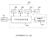
そして、上記のようにして形成したプリントヘッド部は図7に示すようなプリンタ装置に搭載される。このプリンタ装置は、いわゆるシリアル型のプリンタ装置であり、図7中に示すように、被印刷物であるプリント紙31が支持されるドラム32と、上記プリント紙31に記録を行うプリントヘッド部33により主に構成されるものであり、前述のようにして形成したプリントヘッド部を搭載する。
【0053】
このとき、上記プリント紙31は、ドラム32の軸方向に平行に設けられた紙圧着ローラ34により、ドラム32に圧着保持されている。また、上記ドラム32の外周近傍には、送りネジ35がドラム32の軸方向に平行に設けられている。そして、この送りネジ35には、プリントヘッド部33が保持されている。すなわち、かかるプリントヘッド部33は、送りネジ35の回転によって、図中矢印Mで示すようにドラム32の軸方向に移動するようになっている。
【0054】
一方、ドラム32は、プーリ36、ベルト37、プーリ38を介してモータ39により図中矢印mで示すように回転駆動される。さらに、送りネジ35及びモータ39の回転とプリントヘッド部33は、ヘッドドライブ,ヘッド送り制御,ドラム回転制御40により印画データ及び制御信号41に基づいて駆動制御される。
【0055】
上記の構成においては、プリントヘッド部33が移動して1行分の印字を行うと、ドラム32を1行分だけ回転させて次の印字を行う。プリントヘッド部33が移動し、印画する場合は、一方向の場合と往復方向の場合とがある。
【0056】
このようなプリンタ装置における印字及び制御系のブロック図を図8に示す。上記プリンタ装置は図8中に示す制御部50によって制御されている。この制御部55は信号処理制御回路52、ドライバ53、メモリ55、各種制御モータ駆動その他57及び補正56によって構成されている。信号処理制御回路52はCPU又はDSP(Digital Signal Processor)構成でなる。
【0057】
そして、印字データ、操作部信号及び外部制御信号などの信号入力51は、制御部50の信号処理制御回路52に入力され、この信号処理制御回路52において印字順番に揃えられて、ドライバ53を介して吐出信号とともにヘッド54(プリントヘッド部33)に送られ、ヘッド54を駆動制御する。印字順番は、ヘッド54や印字部の構成で異なり、また印字データの入力順番との関係もあり、必要に応じてラインバッファメモリや1画面メモリなどのメモリ55に一旦記録してから取り出す。
【0058】
なお、マルチヘッドでノズル数が非常に多い場合には、ヘッド54にICを搭載してヘッド54に接続する配線数を減らすようにする。また、信号処理制御回路52には、補正56が接続されており、γ補正、カラーの場合の色補正、各ヘッドのばらつき補正などを行う。補正56には、予め決められた補正データをROM(read only memory)マップ形式で格納しておき、外部条件、例えばノズル番号、温度、入力信号などに応じて取り出すようにするのが一般的である。
【0059】
信号処理制御回路52は、前述のようにCPUやDSP構成としてソフトウエアで処理するのが一般的であり、処理された信号は各種制御モータ駆動その他57に送られる。各種制御モータ駆動その他57では、ドラム及び送りネジを回転駆動するモータの駆動、同期、ヘッドのクリーニング、プリント紙の供給、排出などの制御を行う。また、信号には、印字データ以外の操作部信号や外部制御信号が含まれることは言うまでもない。
【0060】
次に、上記プリントヘッドの駆動回路を図9に示す。すなわち、デジタル中間調データが他ブロックより供給され、シリアルパラレル変換回路61により各定量媒体定量部(第1の積層型ピエゾ素子21)制御回路63および吐出制御回路64に送られる。シリアルパラレル変換回路61より与えられたデジタル中間調データが所定のしきい値以下の場合は、定量媒体定量および吐出は行わない。印字タイミングになると、他ブロックから印字トリガが出力され、タイミング制御回路62がそれを検出し、所定のタイミングで定量媒体定量部コントロール信号と吐出コントロール信号をそれぞれ定量媒体定量部(第1の積層型ピエゾ素子21)制御回路63および吐出制御回路64に出力する。それぞれの信号は、後述するタイミングで出力される。これにしたがって、定量媒体定量部(第1の積層型ピエゾ素子21)65および吐出部(第2の積層型ピエゾ素子24)66に所定電圧が印加される。
【0061】
次に、プリントヘッド部の駆動電圧の印加タイミングチャートを図10に示す。先ず図中(A)で示す時点においては、第1の積層型ピエゾ素子21の駆動電圧を10Vとし、第2の積層型ピエゾ素子24の駆動電圧を15Vとして、正の電圧を加えておく。なお、図10中においては、横軸を時間とし、縦軸を第1の積層型ピエゾ素子21の駆動電圧と第2の積層型ピエゾ素子24の駆動電圧としている。
【0062】
このとき、図示しない定量媒体タンクから定量媒体供給室17、定量媒体圧力室15、定量媒体導入口6を介して定量媒体ノズル10には先端まで定量媒体が充填されてメニスカスが形成され、図示しない吐出媒体タンクから吐出媒体供給室18、吐出媒体圧力室16、吐出媒体導入口7を介して吐出媒体ノズル11にも先端まで吐出媒体が充填されてメニスカスが形成されて待機状態となっている。なお、この時点においては、第1の積層型ピエゾ素子21と第2の積層型ピエゾ素子24は収縮しており、振動板13のこれらと接する部分が引き上げられ、定量媒体圧力室15及び吐出媒体圧力室16の体積は増大した状態となされている。本例のプリンタ装置のプリントヘッドにおいては、定量媒体ノズル10と吐出媒体ノズル11が別個に設けられていることから、定量媒体と吐出媒体が接触することは無く、この待機状態で自然に混合することはない。
【0063】
次に、図10中(B)で示す時点において第1の積層型ピエゾ素子21の駆動電圧を徐々に下げ始め、図中(D)で示す時点まで50μsecかけて零Vまで下げる。すると、第1の積層型ピエゾ素子21は伸長し、振動板13中のこれと接する部分を押圧し、定量媒体圧力室15の体積が減少する。そのため、図10中(B)で示す時点と図中(D)で示す時点間である図中(C)で示す時点においては、定量媒体ノズル10から定量媒体が押し出される。本例においては、定量媒体ノズル10が吐出媒体ノズル11に徐々に近づくように形成されていることから、定量媒体は吐出媒体ノズル11に向けて押し出される。
【0064】
そして、図10中(D)で示す時点から図10中(E)で示す時点間、50μsecの間、この状態で保持する。すると、図10中(E)で示す時点においては、定量媒体と吐出媒体が接触して表面張力によって結合した状態になる。
【0065】
なお、このとき、本例のプリンタ装置においては、定量媒体ノズル10と吐出媒体ノズル11が互いに隣合って開口するように形成されていることから、定量媒体ノズル10から定量媒体が吐出媒体ノズル11に向けて安定して供給される。
【0066】
続いて、図10中(E)で示す時点から第1の積層型ピエゾ素子21の駆動電圧を徐々に元の値まで上昇させていく。すると、第1の積層型ピエゾ素子21は再度収縮することから、定量媒体圧力室15の体積が増大し、定量媒体は定量媒体ノズル10に引き込まれ始める。
【0067】
そして、図10中(E)で示す時点よりも遅い時点である図10中(F)で示す時点から図10中(G)で示す時点間、5μsecかけて第2の積層型ピエゾ素子24の駆動電圧を15Vから零Vまで下げる。すると、第2の積層型ピエゾ素子24が伸長し、これと接する振動板13を押圧し、吐出媒体圧力室16の体積が減少する。その結果、図10中(F)で示す時点においては、吐出媒体が吐出媒体ノズル11より押し出され始め、これと接触している定量媒体の一部も共に押し出され始める。
【0068】
さらに、図10中(G)で示す時点と図10中(I)で示す時点間、12μsecの間、この状態で保持する。すると、図10中(G)で示す時点と図10中(I)で示す時点の間である図10中(H)で示す時点においては、吐出媒体は定量媒体と共に吐出媒体ノズル11からさらに押し出された状態となる。
【0069】
このとき、第1の積層型ピエゾ素子21の駆動電圧は上昇を続けていることから、定量媒体は吐出媒体と接触している部分を残存させるようにして定量媒体ノズル10内に引き込まれていく。
【0070】
次に、図10中(I)で示す時点から第2の積層型ピエゾ素子24の駆動電圧を徐々に上昇させていく。すると、第2の積層型ピエゾ素子24が再度収縮し始め、吐出媒体圧力室16の体積が増大していく。その結果、図10中(I)よりも若干後の時点である図10中(J)で示す時点においては、定量媒体と吐出媒体の混合した混合溶液と吐出媒体間にくびれが発生し始める。なお、この時点において第1の積層型ピエゾ素子21の駆動電圧は元の10Vに戻り、この後はこの状態で保持される。
【0071】
そして、図10中(J)で示す時点よりも後の時点である図10中(K)で示す時点においては、混合溶液が吐出媒体から引きちぎれ、吐出媒体ノズル11より吐出され、吐出媒体は吐出媒体ノズル11内に引き込まれる。
【0072】
さらに図10中(K)で示す時点よりも後の時点である図10中(L)で示す時点において第2の積層型ピエゾ素子24の駆動電圧は元の15Vに戻る。なお、図10中(I)で示す時点から図10中(L)で示す時点間は100μsecである。この時点においては、混合溶液は球体をなして図示しない被記録材にむけて飛翔を続けており、この後被記録材に被着して記録がなされる。
【0073】
なお、図10中(J)で示す時点から図10中(L)で示す時点の間において定量媒体は毛細管力により定量媒体ノズル10内に徐々に充填されていき、図10中(L)で示す時点においては、定量媒体ノズル10の先端まで充填される。ただし、図10中(L)で示す時点においては、定量媒体の先端は若干振動して盛り上がりを形成する。
【0074】
さらに、図10中(L)で示す時点よりも後の図10中(M)で示す時点においては、吐出媒体が定量媒体と同様に毛細管力によって吐出媒体ノズル11内に充填されてくるが、その先端部は慣性により若干振動して盛り上がりを形成する。なお、この時点においては定量媒体の振動も収まっている。このとき、本例のプリンタ装置のプリントヘッドにおいては、定量媒体ノズル10及び吐出媒体ノズル11がステンレススチールよりなる第3のプレート9に形成されていることから定量媒体ノズル10と定量媒体の接触角及び吐出媒体ノズル11と吐出媒体の接触角が小さく、充填速度は速く、駆動周波数を高速化して記録を高速化することが可能である。
【0075】
さらにまた、図10中(M)で示す時点よりも後の図10中(N)で示す時点においては、吐出媒体の振動も収まり待機状態に戻る。
【0076】
なお、本例においては、吐出周期を1msec(周波数1kHz)とし、この間に定量媒体の定量混合と混合液滴の吐出を行う。そして、第1の積層型ピエゾ素子21の最大駆動電圧を10V、第2の積層型ピエゾ素子24の駆動電圧を15Vとしている。
【0077】
印刷を行うには、上記動作を繰り返せば良いが、濃度階調を表現するには、ドット毎にインク濃度を変化させる必要がある。本例においては、図10中に示すように定量時の第1の積層型ピエゾ素子21の駆動パルスの振幅(電圧)を10Vだったものを例えば4Vとし、定量されるインクの量を減らして低濃度のドットを形成する等して濃度階調を表現している。なお、駆動パルスの幅を増減しても同様の効果が得られる。
【0078】
また、本発明は、いわゆるライン型のプリンタ装置の製造にも適用可能である。このライン型のプリンタ装置は、図11に示すような構成を有する。なお、図11中においては、図7との対応部分には同一符号を付して示し、その説明を省略するとともに、制御機構を示す部分の図示を省略する。
【0079】
このライン型の液体噴射記録装置は、図示しない多数のプリントヘッドがライン状に配置されてなるラインヘッド部73がドラム32の軸方向に固定して設けられている。このライン型の液体噴射記録装置においては、ラインヘッド部73が1行分の印字を同時に行うようになされており、一行分の印字が完了すると図中矢印mで示す方向にドラム32を1行分だけ回転させて次の行の印字を行うようになされている。この場合、全ラインを一括して印字したり、複数ブロツクに分割したり、1行おきに交互に印字する方法が考えられる。
【0080】
上述の例においては、インクと希釈液を混合吐出するプリンタ装置の例について述べたが、本発明がインクのみを吐出するプリンタ装置の製造にも適用可能であることは言うまでもない。なお、インクを定量媒体として希釈液を吐出媒体とした場合は比較的低濃度の階調表現力に優れ、希釈液を定量媒体としてインクを吐出媒体とした場合は比較的高濃度の階調表現力に優れる。
【0081】
【発明の効果】
以上の説明からも明らかなように、本発明のプリンタ装置の製造方法においては、板材の一方の主面に臨んで開口するように、圧力室を形成する溝部を少なくとも1つ形成し、これに連通し、他方の主面に臨んで開口するノズルをCuレーザ光を照射することにより形成してノズル形成部材を形成し、圧力室を形成する溝部を塞ぐ蓋部を設け、圧力室に圧力を印加する圧力印加手段を設ける。このとき板材の少なくともノズル形成部分がステンレススチールよりなるため、ノズルが加工精度,加工速度良好に形成され、量産性を損なうことなく、ノズルの小径化、多ノズル化、隣接するノズル間の狭ピッチ化への対応がなされ、また、ノズルが形成される板材の構成材料として剛性の高いステンレススチールが使用されることから、板材の剛性の低下に起因する隣接ノズル間の媒体の混入の発生が抑えられ、インク或いは希釈液との接触角が小さく、駆動周波数の高速化に対応するノズルが形成され、記録画像の高精細化、記録の高速化を可能とするプリンタ装置の製造が可能となる。さらに圧力室を形成する第1のプレート、上記圧力室から上記ノズルへ吐出媒体を導入する導入口が設けられた第2のプレート、上記ノズルが形成されるステンレススチールの板材からなる第3のプレートを積層した後に、定量媒体ノズル及び吐出媒体ノズルを形成するため、ノズル内が接着剤により埋まってしまうこともない。
【図面の簡単な説明】
【図1】本発明を適用したプリンタ装置の製造方法を工程順に示すものであり、オリフィスプレートを形成する第1のプレートを用意する工程を示す要部拡大断面図である。
【図2】本発明を適用したプリンタ装置の製造方法を工程順に示すものであり、オリフィスプレートを形成する第2のプレートを用意する工程を示す要部拡大断面図である。
【図3】本発明を適用したプリンタ装置の製造方法を工程順に示すものであり、オリフィスプレートを形成する第3のプレートを用意する工程を示す要部拡大断面図である。
【図4】本発明を適用したプリンタ装置の製造方法を工程順に示すものであり、オリフィスプレートを形成する工程を示す要部拡大断面図である。
【図5】本発明を適用したプリンタ装置の製造方法を工程順に示すものであり、オリフィスプレートを形成し、振動板を配し、ピエゾユニットを配する工程を示す要部概略断面図である。
【図6】本発明を適用したプリンタ装置の製造方法を工程順に示すものであり、オリフィスプレートを形成し、振動板を配し、ピエゾユニットを配する工程を示す要部拡大断面図である。
【図7】プリンタ装置の一例を示す要部概略斜視図である。
【図8】プリンタ装置の一例の印字及び制御系のブロック図である。
【図9】プリントヘッドの駆動回路を示す回路ブロック図である。
【図10】プリントヘッドの駆動電圧の印加タイミングを示すチャートである。
【図11】プリンタ装置の他の例を示す要部概略斜視図である。
【符号の説明】
1 第1の孔部、2 第2の孔部、3 第1のプレート、8 第2のプレート、9 第3のプレート、10 定量媒体ノズル、11 吐出媒体ノズル、12 オリフィスプレート、19 第1のピエゾユニット、20 第2のピエゾユニット[0001]
BACKGROUND OF THE INVENTION
The present invention relates to a method for manufacturing a printer apparatus that discharges only a discharge medium or a mixture of a discharge medium and a quantitative medium. More specifically, an object of the present invention is to provide a method for manufacturing a printer device in which a nozzle is formed by irradiating a Cu laser beam to enable manufacturing of a printer device that can cope with higher definition of recorded images and higher speed of recording. To do.
[0002]
[Prior art]
In recent years, document creation using a computer called desktop publishing has been actively performed especially in offices. Recently, not only characters and figures but also color natural images such as photographs are used for letters and figures. The demand for output is also increasing. In addition, it is required to print high-quality natural images, and reproduction of halftones has become important.
[0003]
In response to such requirements, ink droplets are continuously ejected with a pair of electrodes provided, and the ink droplets are deflected and printed on a print medium such as paper or film only when necessary. Near-type printer devices and so-called on-demand printer devices that eject ink droplets from nozzles and print on printing media such as paper and film only when necessary according to the print signal have been used. In particular, on-demand printers are rapidly becoming popular in recent years because they can be reduced in size and cost.
[0004]
Various methods for ejecting ink droplets have been proposed in this way, but a method using a piezo element or a method using a heating element is common. The former is a method in which a pressure change is applied to ink to be filled by causing a pressure change in the ink pressure chamber by deformation of the piezo element, and fine ink droplets are ejected. The latter is a method in which ink droplets are ejected by the pressure of bubbles generated by heating and boiling ink by causing a heat generating element to generate heat rapidly.
[0005]
Various methods have been proposed as a method for reproducing the above-described halftone with an on-demand printer that discharges the ink droplets. In other words, the first method is to control the droplet size to be ejected by changing the voltage or pulse width of the voltage pulse applied to the piezo element or the heating element, and to express the gradation by changing the diameter of the print dot. It is done.
[0006]
However, according to this method, if the voltage or pulse width applied to the piezo element or the heating element is too low, ink cannot be ejected, so there is a limit to the minimum droplet diameter, the number of gradation levels that can be expressed is small, and particularly low density. It is difficult to express and is insufficient to print out a natural image.
[0007]
Further, as a second method, there is a method in which one pixel is constituted by a matrix of, for example, 4 × 4 dots without changing the dot diameter, and gradation representation is performed using a so-called dither method in units of this matrix. It is done. In this case, 17 gradations can be expressed.
[0008]
However, with this method, for example, when printing is performed at the same dot density as in the first method, the resolution is 1/4 of the first method, and the roughness is conspicuous, which is not sufficient for printing out a natural image. is there.
[0009]
Therefore, the present inventors can control the density of the printed dots by changing the density of the ejected ink droplets by mixing the ink and the diluent when ejecting the ink, A printer apparatus that prints out a natural image without causing degradation in resolution has been proposed.
[0010]
As a print head of such a printer apparatus, an ejection medium nozzle into which an ejection medium is introduced and a quantitative medium nozzle into which a quantitative medium is introduced are opened so as to be adjacent to each other. The medium is oozed toward the ejection medium nozzle, mixed with the ejection medium in the vicinity of the ejection medium nozzle opening, and the ejection medium is ejected from the ejection medium nozzle together with the ejection medium mixed with the quantitative medium to eject the quantitative medium and the ejection medium. A print head that mixes and discharges the medium in the in-plane direction of the quantitative medium nozzle and the discharge medium nozzle can be used. Also in this printer apparatus, the fixed quantity medium pressure chamber or the discharge medium pressure chamber is connected to the fixed quantity medium nozzle or the discharge medium nozzle into which the fixed quantity medium or the discharge medium is introduced, and the nozzle is obtained by applying pressure to these pressure chambers. The quantitative medium or the discharge medium is extruded from the above.
[0011]
In such a printer device, the amount of the quantification medium, which is either ink or dilution liquid, is changed, and the dot density is changed by changing the mixing ratio of the ink and the dilution liquid, thereby producing a natural image. Print out. Note that one of the quantitative medium and the ejection medium may be ink and the remaining one may be a diluent.
[0012]
[Problems to be solved by the invention]
In both the above-described printer device that ejects only ink and the printer device that ejects mixed ink and diluent, a nozzle is connected to a pressure chamber filled with ink or diluent, and pressure is applied to the pressure chamber. By doing so, the ink or diluent is pushed out from the nozzle. Therefore, each nozzle has a great influence on the extrusion operation of each liquid, and greatly affects the printing performance of the printer apparatus.
[0013]
Incidentally, in these printer apparatuses, the nozzles are generally formed on a plate material called an orifice plate. The nozzle is machined by a drill, finely processed by electric discharge machining, a method in which the orifice plate itself is formed of silicon and then finely processed by anisotropic etching, and the orifice plate itself is formed of glass and etched. It is formed by a method of fine processing, a method of forming an orifice plate itself by photolithography, patterning the plate and processing it by plating, or a fine processing by a carbon dioxide gas laser or a YAG laser.
[0014]
In recent years, there has been a demand for high-definition recording images and high-speed recording, and accordingly, nozzle diameter reduction, multiple nozzles, and narrow pitches between adjacent nozzles have been required. However, processing by the method as described above suppresses the occurrence of mixing of media between adjacent nozzles due to a decrease in the rigidity of the orifice plate, and forms the nozzles with high productivity so as to satisfy the above requirements. It is difficult. In particular, in a printer device that mixes and discharges ink and dilution liquid, it is necessary to form both the quantitative medium nozzle and the discharge medium nozzle, and when the ink and dilution liquid are mixed, an accurate density gradation can be realized. Therefore, it is more difficult to form a nozzle that meets the above-described requirements by the above-described method.
[0015]
For example, in machining with a drill, it is difficult to reduce the diameter of the nozzle, the processing efficiency is not good, and in the fine processing by electric discharge machining, it is possible to cope with a certain size reduction. In addition, when mass processing is not good and silicon is finely processed by anisotropic etching, the cost of silicon constituting the orifice plate is expensive and the processing time becomes long, and mass productivity is not good. It is difficult to meet the above requirements.
[0016]
Furthermore, in the method of etching and finely processing glass, the processing time becomes long. In the method of forming the orifice plate itself by photolithography and patterning and processing it by plating, from photolithography The manufacturing process up to plating is long, auxiliary materials such as a substrate and resist are necessary, mass productivity is not good, and it is difficult to meet the above requirements.
[0017]
Further, in the fine processing by the carbon dioxide laser and the YAG laser, the laser output is not sufficient, and the accuracy of the shape and dimensions of the nozzle to be formed cannot be sufficiently satisfied. Have difficulty. This is because fine processing using a carbon dioxide laser or YAG laser is a processing method in which a material is gradually melted by heat to form holes. For example, the processing using a YAG laser does not produce a clean circular nozzle shape and processing. Foreign matter sometimes generated adheres around the nozzle opening. Further, since the wavelength is long (carbon dioxide laser: 10.6 μm, YAG laser: 1.06 μm), the beam spot diameter cannot be reduced to a small size, and it is very difficult to process a small diameter nozzle of 50 μm or less.
[0018]
On the other hand, an excimer that is generated by a device that oscillates ultraviolet light of a short pulse (15 to 35 ns) by exciting a mixed gas of a rare gas and a halogen gas and often uses a KrF / XeCl / ArF laser. Laser microfabrication is also mentioned as a nozzle processing method, which satisfies both the processing accuracy and processing speed sufficiently and can meet the above requirements. The excimer laser has an oscillation energy of several hundred mJ / pulse and a pulse repetition frequency of about 30 to 300 Hz. However, usable materials are limited to resin materials such as polyetherketone, polyimide, polyetherimide, and polyethersulfone, and metals such as stainless steel, opaque ceramics, and silicon can be processed in the atmosphere. Impossible.
[0019]
Incidentally, in order to achieve high-speed recording, it is necessary to increase the drive frequency. For that purpose, the speed at which these are filled in the nozzles by capillary action after ejecting the ink or diluent is very important. The filling speed is greatly affected by the contact angle between the ink or diluent and the material constituting the nozzle portion, and it is preferable that the contact angle be small. Thus, in order to reduce the contact angle between the ink or diluent and the material constituting the nozzle portion, the nozzle portion is preferably formed of an inorganic material such as stainless steel, ceramics, or silicon.
[0020]
Therefore, in the microfabrication using the excimer laser described above, it is difficult to form a nozzle that can respond to the above-mentioned demands, but can cope with an increase in driving frequency.
[0021]
If the fine processing by the carbon dioxide laser and YAG laser is used, it is possible to process the inorganic material as described above. However, as described above, the processing accuracy is not sufficient, and this method is used as described above. It is difficult to form a nozzle made of a new material. In particular, in a printer device that mixes and discharges ink and diluting liquid, the opening diameter of a nozzle for quantifying a quantitative medium may be 20 μm or less, and it is practically impossible to form such a nozzle.
[0022]
Therefore, the present invention has been proposed in view of the conventional situation, while suppressing the occurrence of mixing of the medium between adjacent nozzles due to the decrease in the rigidity of the orifice plate, without reducing the mass productivity, the small diameter of the nozzle The number of nozzles can be increased, the number of nozzles can be reduced, and the pitch between adjacent nozzles can be reduced. Also, the nozzle can be formed to increase the drive frequency, and the recorded image can be refined and the recording speed increased. It is an object of the present invention to provide a method for manufacturing a printer device that makes it possible to manufacture the printer device.
[0023]
[Means for Solving the Problems]
As a result of intensive studies by the present inventors to achieve the above-described object, it is possible to use stainless steel as a material to be processed while achieving processing accuracy and processing speed equivalent to those of an excimer laser when using a Cu laser. It has been found that it is possible and suitable for forming nozzles.
[0024]
That is, the present invention forms at least one groove portion that forms a pressure chamber so as to open toward one main surface of the plate material, and forms a nozzle that communicates with this and opens toward the other main surface. Forming a nozzle forming member, providing a lid portion that closes a groove forming the pressure chamber, and providing a pressure applying means for applying pressure to the pressure chamber;A first plate that forms the pressure chamber; a second plate that is provided with an inlet for introducing a discharge medium from the pressure chamber to the nozzle; and a third plate that is made of a stainless steel plate on which the nozzle is formed. Then, the nozzle is formed by irradiating the third plate with Cu laser light after being laminated and adhered.
[0025]
The Cu laser is a visible light laser and has two wavelengths of 510.8 nm and 578.2 nm. Cu is vaporized by heating to 1500 ° C. in an Ne atmosphere, and the mixed gas is generated by a device that oscillates light of a short pulse (10 ns to 50 ns) by discharging excitation, and the oscillation energy is about 0.5 The oscillation frequency can be 10 kHz or more at ˜20 mJ / pulse.
[0026]
Although processing by this Cu laser is thermal processing, it does not melt, but enables processing such as evaporating the material to be processed at a high energy density at a stretch, and the thermal influence on the periphery of the hole is extremely high Small processing is possible. Note that the minimum hole diameter that can be processed is several μm in terms of the opening diameter, and can sufficiently cope with the processing of the nozzles of the printer device.
[0028]
Workable materials that can be used in processing with Cu laser include copper, brass, aluminum, mild steel, stainless steel, titanium, tungsten, molybdenum, nickel, gold, zirconium, alumina, kevlar, paper, carbon, silicon, diamond, and various types. Wide range of glass.
[0029]
In the printer device manufacturing method of the present invention, a pressure chamber filled with a discharge medium may be formed as a pressure chamber, and a pressure chamber filled with a quantitative medium and a pressure chamber filled with a discharge medium are formed as pressure chambers. You may do it.
[0030]
In the manufacturing method of the printer device of the present invention, at least one groove for forming the pressure chamber is formed so as to open toward one main surface of the plate member, communicate with this, and face the other main surface. The nozzle to be opened is formed by irradiating Cu laser light to form a nozzle forming member, a lid for closing the groove forming the pressure chamber is provided, and a pressure applying means for applying pressure to the pressure chamber is provided. Is formed with good processing accuracy and processing speed, and without compromising mass productivity, the nozzle diameter is reduced, the number of nozzles is increased, and the pitch between adjacent nozzles is reduced. Since a highly rigid inorganic material is used as a constituent material, the occurrence of mixing of media between adjacent nozzles due to a decrease in the rigidity of the plate material is suppressed, the contact angle with ink or diluent is small, and the drive frequency is reduced. Nozzle corresponding to the speed reduction is formed.
[0031]
DETAILED DESCRIPTION OF THE INVENTION
Hereinafter, specific embodiments of the present invention will be described in detail with reference to the drawings. In this example, an example in which the present invention is applied to a method of manufacturing a printer device that mixes and discharges ink and diluent is shown, and either one of ink and diluent is used as a quantitative medium, and the other is used as a discharge medium. Just do it.
[0032]
In this example, first, a plate material on which nozzles and pressure chambers called orifice plates are formed is prepared. That is, in this example, as shown in FIG. 1, the
[0033]
Subsequently, as shown in FIG. 2, the
[0034]
Further, as shown in FIG. 3, a
[0035]
Next, the
[0036]
In this example, the quantitative medium nozzle and the ejection medium nozzle are formed at predetermined positions on the
[0037]
In this way, if the quantitative medium nozzle and the ejection medium nozzle are formed after the
[0038]
In addition, since stainless steel, which is a highly rigid inorganic material, is used as the material for forming the
[0039]
As shown in FIGS. 4 and 5, the
[0040]
In this example, a
[0041]
That is, the
[0042]
Subsequently, as shown in FIGS. 5 and 6, the
[0043]
Further, as shown in FIGS. 5 and 6, a first
[0044]
As the first and second laminated
[0045]
For this reason, the former stacked piezo element extends in the longitudinal direction of the first and
[0046]
On the other hand, in the latter laminated piezoelectric element, when a voltage is applied, it extends in a direction orthogonal to the longitudinal direction of the first and
[0047]
In the first
[0048]
In the manufacturing method of the printer device of this example, since the quantitative medium nozzle and the ejection medium nozzle are formed by irradiating Cu laser light, these nozzles are formed with good processing accuracy and processing speed, and the mass productivity is impaired. Therefore, it is possible to cope with the reduction in the diameter of the nozzle, the increase in the number of nozzles, and the reduction in the pitch between adjacent nozzles. In addition, since processing is performed by irradiating Cu laser light, the material for forming the plate on which these nozzles are formedHighly rigid stainless steel can be used,Occurrence of mixing of media between adjacent nozzles due to a decrease in rigidity of the plate material is suppressed, a contact angle with ink or a diluting liquid is small, and a nozzle corresponding to an increase in driving frequency is formed.
[0049]
Furthermore, if stainless steel is used as the material for the plate on which the nozzle is formed as in this example, the wettability of the stainless steel itself is high, so there is no need to perform hydrophilic treatment as in the conventional case, and productivity is also improved. It is good. Further, since the wettability is high as described above, it is difficult to cause inconvenience such as mixing of bubbles into the nozzle, and the printing performance is improved.
[0050]
Also, as in this example, if stainless steel is used as the material for forming the pressure chamber, supply chamber, and inlet, the stainless steel itself has high wettability. Inconveniences such as air bubbles are less likely to occur, and printing performance is improved.
[0051]
Furthermore, as in this example, if stainless steel is used as the material for forming the plate on which the nozzles are formed, it is possible to perform liquid repellent processing around the nozzle openings.
[0052]
The print head portion formed as described above is mounted on a printer apparatus as shown in FIG. This printer apparatus is a so-called serial type printer apparatus. As shown in FIG. 7, the printer apparatus includes a
[0053]
At this time, the
[0054]
On the other hand, the
[0055]
In the above configuration, when the
[0056]
A block diagram of a printing and control system in such a printer apparatus is shown in FIG. The printer apparatus is controlled by the
[0057]
Then, signal
[0058]
When the number of nozzles is very large in the multi-head, an IC is mounted on the
[0059]
The signal processing control circuit 52 is generally processed by software as a CPU or DSP configuration as described above, and the processed signal is sent to various control motor drives and
[0060]
Next, a drive circuit for the print head is shown in FIG. That is, digital halftone data is supplied from another block, and is sent by the serial /
[0061]
Next, FIG. 10 shows an application timing chart of the drive voltage of the print head unit. First, at the time indicated by (A) in the drawing, a positive voltage is applied with the driving voltage of the first laminated
[0062]
At this time, the quantitative
[0063]
Next, the drive voltage of the first laminated
[0064]
Then, the state is maintained in this state for 50 μsec from the time indicated by (D) in FIG. 10 to the time indicated by (E) in FIG. Then, at the time indicated by (E) in FIG. 10, the quantitative medium and the ejection medium come into contact with each other by surface tension.
[0065]
At this time, in the printer device of this example, since the fixed amount
[0066]
Subsequently, the driving voltage of the first laminated
[0067]
Then, from the time point shown in FIG. 10F, which is a time point later than the time point shown in FIG. 10E, to the time point shown in FIG. 10G, the second stacked
[0068]
Further, this state is maintained for 12 μsec between the time indicated by (G) in FIG. 10 and the time indicated by (I) in FIG. Then, at the time indicated by (H) in FIG. 10, which is between the time indicated by (G) in FIG. 10 and the time indicated by (I) in FIG. 10, the discharge medium is further pushed out from the
[0069]
At this time, since the driving voltage of the first laminated
[0070]
Next, the driving voltage of the second stacked
[0071]
Then, at the time indicated by (K) in FIG. 10, which is a time later than the time indicated by (J) in FIG. 10, the mixed solution is torn from the discharge medium and discharged from the
[0072]
Further, at the time indicated by (L) in FIG. 10, which is a time later than the time indicated by (K) in FIG. 10, the drive voltage of the second stacked
[0073]
Note that the quantitative medium is gradually filled into the quantitative
[0074]
Furthermore, at the time indicated by (M) in FIG. 10 after the time indicated by (L) in FIG. 10, the discharge medium is filled into the
[0075]
Furthermore, at the time indicated by (N) in FIG. 10 after the time indicated by (M) in FIG. 10, the vibration of the ejection medium is also settled and returns to the standby state.
[0076]
In this example, the discharge cycle is set to 1 msec (
[0077]
In order to perform printing, the above operation may be repeated. However, in order to express density gradation, it is necessary to change the ink density for each dot. In this example, as shown in FIG. 10, the amplitude (voltage) of the driving pulse of the first laminated
[0078]
The present invention can also be applied to the production of a so-called line type printer apparatus. This line type printer apparatus has a configuration as shown in FIG. In FIG. 11, parts corresponding to those in FIG. 7 are denoted by the same reference numerals, description thereof is omitted, and illustration of a part showing the control mechanism is omitted.
[0079]
This line type liquid jet recording apparatus is provided with a
[0080]
In the above-described example, the example of the printer device that mixes and discharges the ink and the diluent is described. However, it goes without saying that the present invention can also be applied to the manufacture of a printer device that discharges only ink. When ink is used as the quantitative medium and the diluted liquid is used as the ejection medium, the gradation expression with a relatively low density is excellent. When the diluent is used as the quantitative medium and the ink is used as the ejection medium, relatively high density gradation is expressed. Excellent power.
[0081]
【The invention's effect】
As is clear from the above description, in the printer device manufacturing method of the present invention, at least one groove for forming the pressure chamber is formed so as to open toward one main surface of the plate material, and Communicating, forming a nozzle forming member by irradiating a Cu laser beam with a nozzle that opens facing the other main surface, forming a nozzle forming member, providing a lid portion that closes the groove forming the pressure chamber, and applying pressure to the pressure chamber A pressure applying means for applying is provided. At this time, at least the nozzle forming part of the plate material is made of stainless steel, so the nozzle is formed with good processing accuracy and processing speed, and the nozzle diameter is reduced, the number of nozzles is increased, and the pitch between adjacent nozzles is reduced without sacrificing mass productivity. In addition, since high-stiffness stainless steel is used as the material for the plate on which the nozzles are formed, medium contamination between adjacent nozzles due to a reduction in plate rigidity is suppressed. As a result, a nozzle having a small contact angle with the ink or the diluting liquid and corresponding to a high drive frequency is formed, and it becomes possible to manufacture a printer device that enables high-definition recording and high-speed recording.Furthermore, a first plate forming a pressure chamber, a second plate provided with an introduction port for introducing a discharge medium from the pressure chamber to the nozzle, and a third plate made of a stainless steel plate material on which the nozzle is formed Since the quantitative medium nozzle and the discharge medium nozzle are formed after the layers are stacked, the nozzle is not filled with the adhesive.
[Brief description of the drawings]
FIG. 1 is a main part enlarged cross-sectional view showing a step of preparing a first plate for forming an orifice plate, showing a method of manufacturing a printer apparatus to which the present invention is applied in the order of steps.
FIG. 2 is a main part enlarged cross-sectional view showing a step of preparing a second plate for forming an orifice plate, showing a method of manufacturing a printer apparatus to which the present invention is applied in the order of steps;
FIG. 3 is a main part enlarged sectional view showing a step of preparing a third plate for forming an orifice plate, showing a method of manufacturing a printer apparatus to which the present invention is applied in the order of steps;
FIG. 4 is a main part enlarged cross-sectional view showing a step of forming an orifice plate, illustrating a method of manufacturing a printer apparatus to which the present invention is applied in the order of steps;
FIG. 5 is a schematic cross-sectional view of an essential part showing a process of manufacturing a printer apparatus to which the present invention is applied, showing a process of forming an orifice plate, arranging a diaphragm, and arranging a piezo unit.
FIG. 6 is a main part enlarged cross-sectional view showing a method of manufacturing a printer device to which the present invention is applied, showing a step of forming an orifice plate, arranging a diaphragm, and arranging a piezo unit.
FIG. 7 is a main part schematic perspective view showing an example of a printer apparatus.
FIG. 8 is a block diagram of a printing and control system as an example of a printer apparatus.
FIG. 9 is a circuit block diagram showing a drive circuit of the print head.
FIG. 10 is a chart showing the application timing of the drive voltage of the print head.
FIG. 11 is a main part schematic perspective view showing another example of a printer apparatus.
[Explanation of symbols]
DESCRIPTION OF
Claims (4)
上記圧力室を形成する第1のプレートと、上記圧力室から上記ノズルへ吐出媒体を導入する導入口が設けられた第2のプレートと、上記ノズルが形成されるステンレススチールの板材からなる第3のプレートとを積層し、接着させた後、該第3のプレートにCuレーザ光を照射することにより上記ノズルを形成するプリンタ装置の製造方法。At least one groove forming a pressure chamber is formed so as to open toward one main surface of the plate material, and a nozzle that opens to face the other main surface is formed to communicate with the groove. In the manufacturing method of the printer apparatus, in which the lid portion that closes the groove portion that forms the pressure chamber is provided, and the pressure applying means that applies pressure to the pressure chamber is provided.
A first plate that forms the pressure chamber; a second plate that is provided with an inlet for introducing a discharge medium from the pressure chamber to the nozzle; and a third plate that is made of a stainless steel plate on which the nozzle is formed. A method of manufacturing a printer device in which the nozzles are formed by laminating and adhering the plates to each other and then irradiating the third plate with Cu laser light .
Priority Applications (1)
| Application Number | Priority Date | Filing Date | Title |
|---|---|---|---|
| JP5370397A JP3799720B2 (en) | 1997-03-07 | 1997-03-07 | Method for manufacturing printer device |
Applications Claiming Priority (1)
| Application Number | Priority Date | Filing Date | Title |
|---|---|---|---|
| JP5370397A JP3799720B2 (en) | 1997-03-07 | 1997-03-07 | Method for manufacturing printer device |
Publications (2)
| Publication Number | Publication Date |
|---|---|
| JPH10244675A JPH10244675A (en) | 1998-09-14 |
| JP3799720B2 true JP3799720B2 (en) | 2006-07-19 |
Family
ID=12950197
Family Applications (1)
| Application Number | Title | Priority Date | Filing Date |
|---|---|---|---|
| JP5370397A Expired - Fee Related JP3799720B2 (en) | 1997-03-07 | 1997-03-07 | Method for manufacturing printer device |
Country Status (1)
| Country | Link |
|---|---|
| JP (1) | JP3799720B2 (en) |
-
1997
- 1997-03-07 JP JP5370397A patent/JP3799720B2/en not_active Expired - Fee Related
Also Published As
| Publication number | Publication date |
|---|---|
| JPH10244675A (en) | 1998-09-14 |
Similar Documents
| Publication | Publication Date | Title |
|---|---|---|
| JP4251912B2 (en) | Image forming apparatus | |
| US6312120B1 (en) | Printer | |
| JPH11179926A (en) | Ink jet recording head and manufacture thereof | |
| JP2004042576A (en) | Head drive controller and image recorder | |
| JPH10235881A (en) | Manufacture of printer apparatus | |
| JP3056191B1 (en) | Driving apparatus and method for ink jet printer head | |
| JP3799720B2 (en) | Method for manufacturing printer device | |
| JP2004090542A (en) | Inkjet recorder | |
| JP3045117B2 (en) | Printer device | |
| JP3575120B2 (en) | Printer device and method of manufacturing the same | |
| JPH0538809A (en) | Ink jet head | |
| JP2004058428A (en) | Ink jet recorder | |
| JP3233189B2 (en) | Ink jet recording head and method of manufacturing the same | |
| JP3064455B2 (en) | Inkjet head | |
| JP3297804B2 (en) | Printer device | |
| JP2001063042A (en) | Method and circuit for driving ink jet recording head | |
| JP2002001956A (en) | Ink jet head | |
| JPH11334066A (en) | Ink jet recording head and manufacture thereof | |
| JP3892622B2 (en) | Ink jet recording head driving method and driving apparatus | |
| JP2007118278A (en) | Driving method for inkjet head, inkjet head, and inkjet recording device | |
| JP2003094644A (en) | Ink jet head and ink jet recorder | |
| JPH02297445A (en) | Ink discharger of ink jet printer | |
| JP2000301728A (en) | Manufacture of ink jet printer head | |
| JP2000043257A (en) | Printing apparatus and its manufacture | |
| JP2001353867A (en) | Recording head, ink jet recorder, and its fabricating method |
Legal Events
| Date | Code | Title | Description |
|---|---|---|---|
| A621 | Written request for application examination |
Free format text: JAPANESE INTERMEDIATE CODE: A621 Effective date: 20040302 |
|
| A977 | Report on retrieval |
Effective date: 20050927 Free format text: JAPANESE INTERMEDIATE CODE: A971007 |
|
| A131 | Notification of reasons for refusal |
Effective date: 20051004 Free format text: JAPANESE INTERMEDIATE CODE: A131 |
|
| A521 | Written amendment |
Effective date: 20051205 Free format text: JAPANESE INTERMEDIATE CODE: A523 |
|
| A131 | Notification of reasons for refusal |
Free format text: JAPANESE INTERMEDIATE CODE: A131 Effective date: 20060110 |
|
| A521 | Written amendment |
Free format text: JAPANESE INTERMEDIATE CODE: A523 Effective date: 20060313 |
|
| TRDD | Decision of grant or rejection written | ||
| A01 | Written decision to grant a patent or to grant a registration (utility model) |
Free format text: JAPANESE INTERMEDIATE CODE: A01 Effective date: 20060404 |
|
| A61 | First payment of annual fees (during grant procedure) |
Effective date: 20060417 Free format text: JAPANESE INTERMEDIATE CODE: A61 |
|
| LAPS | Cancellation because of no payment of annual fees |