JP3796188B2 - OFDM communication method and OFDM communication apparatus - Google Patents
OFDM communication method and OFDM communication apparatus Download PDFInfo
- Publication number
- JP3796188B2 JP3796188B2 JP2002107105A JP2002107105A JP3796188B2 JP 3796188 B2 JP3796188 B2 JP 3796188B2 JP 2002107105 A JP2002107105 A JP 2002107105A JP 2002107105 A JP2002107105 A JP 2002107105A JP 3796188 B2 JP3796188 B2 JP 3796188B2
- Authority
- JP
- Japan
- Prior art keywords
- signal
- ofdm
- transmitted
- antenna
- antennas
- Prior art date
- Legal status (The legal status is an assumption and is not a legal conclusion. Google has not performed a legal analysis and makes no representation as to the accuracy of the status listed.)
- Expired - Lifetime
Links
Images


Landscapes
- Cable Transmission Systems, Equalization Of Radio And Reduction Of Echo (AREA)
- Mobile Radio Communication Systems (AREA)
Description
【0001】
【発明の属する技術分野】
本発明はOFDM(Orthogonal Frequency Division Multiplexing)通信方法及びその装置に関し、特に複数のアンテナを用いてそれぞれ異なるデータが重畳された複数のOFDM信号を送信する場合に適用して好適なものである。
【0002】
【従来の技術】
この種のOFDM通信方法では、複数のアンテナから複数のOFDM信号を送信できるので、大容量のデータを高速で送信できるといった利点がある。しかし、受信側で高精度の伝搬路補償や干渉補償を行わないとデータの誤り率特性が劣化することになる。
【0003】
そこで、この種のOFDM通信方法では、図38に示すように、送信側では所定の搬送波(以下これをサブキャリアと呼ぶ)にパイロットシンボル等の既知信号を重畳することでパイロットキャリアを形成し、受信側ではこのパイロットキャリアに基づいて各サブキャリアの周波数オフセット等の伝搬路歪みを補償することで、誤り率特性の良い受信信号を得るようになっている。
【0004】
またOFDM通信方法では、送信側で各サブキャリアに伝搬路推定用プリアンブルを配置したOFDM信号を送信し、受信側でこの伝搬路推定用プリアンブルに基づいて各サブキャリアの位相回転等を補償するようになっている。
【0005】
次に図39を用いて、OFDM通信装置の送受信の原理を説明する。図39では、2つのアンテナAN1、AN2を有するOFDM通信装置(TX)1から2つのアンテナAN3、AN4を有するOFDM通信装置(RX)2にOFDM信号を送信する場合について説明する。ここでOFDM通信装置1の各アンテナAN1、AN2から送信される信号をそれぞれTX1、TX2とする。またOFDM通信装置2の各アンテナAN3、AN4により受信される信号をそれぞれRX1、RX2とする。すると、受信信号RX1、RX2はそれぞれ次式で表すことができる。
【0006】
RX1 = ATX1 + BTX2 ……… (1)
RX2 = CTX1 + DTX2 ……… (2)
但し、(1)式、(2)式において、Aは送信アンテナAN1と受信アンテナAN3との間の伝搬路特性、Bは送信アンテナAN2と受信アンテナAN3との間の伝搬路特性、Cは送信アンテナAN1と受信アンテナAN4との間の伝搬路特性、Aは送信アンテナAN2と受信アンテナAN4との間の伝搬路特性を表すものとする。
【0007】
図40は、OFDM通信装置1から送信されるOFDM送信信号のフレームフォーマットを示す。すなわちアンテナAN1からは図40(a)に示すOFDM信号が送信され、アンテナAN2からは図40(b)に示すOFDM信号が送信される。また図40において、例えばDATA1(N,K)とは、DATA1が示されている時間及び周波数にデータ1に関するNシンボル目がK番目のサブキャリアで送信されていることを表す。
【0008】
ここで受信信号から、上述した送信信号TX1とTX2を受信復調するためには、4つの伝搬路特性A、B、C、Dを推定する必要がある。このためOFDM通信装置1では、送信信号に伝搬路推定用プリアンブルを挿入したり、特定のサブキャリアをパイロットキャリアとしたOFDM信号を送信する。このOFDM信号を受信するOFDM通信装置2では、この伝搬路推定用プリアンブルやパイロットキャリアに基づいて伝搬路特性を求める。
【0009】
4つの伝搬路特性A〜Dは、OFDM通信装置2(図39)において、以下のようにして推定することができる。伝搬路特性AはアンテナAN1から送信された伝搬路推定用プリアンブルをアンテナAN3で受信し、アンテナAN3に対応した信号処理部により求める。特性BはアンテナAN2から送信された伝搬路推定用プリアンブルをアンテナAN3で受信し、アンテナAN3に対応した信号処理部により求める。特性CはアンテナAN1から送信された伝搬路推定用プリアンブルをアンテナAN4で受信し、アンテナAN4に対応した信号処理部により求める。特性ADアンテナAN2から送信された伝搬路推定用プリアンブルをアンテナAN4で受信し、アンテナAN4に対応した信号処理部により求める。
【0010】
次に、OFDM通信装置2は、推定した4つの伝搬路特性A〜Dを用いて、以下の式で表す処理を行うことにより、各アンテナAN1、AN2から送信された信号TX1、TX2を受信復調することができる。
【0011】
DRX1 / ( AD - BC ) - BRX2 / ( AD - BC )
= D ( ATX1 + BTX2 ) / ( AD - BC ) - B ( DTX1 + DTX2 ) / ( AD - BC )
= ( ADTX1 + BDTX2 - BCTX1 - BDTX2 ) / ( AD - BC )
= TX1 ………(3)
−CRX1 / ( AD - BC ) - ARX2 / ( AD - BC )
= −C( ATX1 + BTX2 ) / ( AD - BC ) + A ( CTX1 + DTX2 ) / ( AD - BC )
= ( -ACTX1 - BCTX2 + ACTX1 - ADTX2 ) / ( AD - BC )
= TX2 ………(4)
実際上、伝搬路推定用プリアンブルは以下のように送信される。すなわちアンテナAN1から伝搬路推定用プリアンブルが送信されている時間は、アンテナAN2からは伝搬路推定用プリアンブルを送信しないようにしている。同様に、アンテナAN2から伝搬路推定用プリアンブルが送信されている時間は、アンテナAN2からは伝搬路推定用プリアンブルを送信しないようにしている。
【0012】
また一般にパイロットキャリアは、周波数オフセット検出誤差等による残留位相誤差を補償するために用いられる。すなわち受信時には、パイロットキャリアに重畳された既知信号(パイロット信号)を用いて残留位相誤差を検出し、補償する。実際上、図40に示すように、特定のサブキャリアをパイロットキャリアとして送信する。図40に示す例では、2k+1個のサブキャリアのうち、アンテナAN1の4つのサブキャリアをパイロットキャリアとして送信する。
【0013】
図41は、OFDM通信装置1の送信系の構成を示す。送信系10では、まず送信信号が符号化部11により符号化される。符号化後の信号はプリアンブル挿入部12によりプリアンブルが挿入され、続くパイロットキャリア挿入部13により特定のサブキャリアがパイロットキャリアとなる位置に既知信号(パイロット信号)が挿入される。
【0014】
変調部14により変調処理が施された信号はシリアルパラレル変換部(S/P)15によりシリアルパラレル変換されることにより2系統に分けられる。2系統に分けられた各信号は逆高速フーリエ変換部(IFFT)16、17により逆高速フーリエ変換処理されることにより、各IFFT16、17により直交周波数分割多重されてOFDM信号が得られる。ここでIFFT16の出力信号1は、図示しない無線送信部により所定周波数の搬送波の乗算処理等の無線送信処理が施された後、アンテナAN1(図39)から発信される。同様にIFFT17の出力信号2は、図示しない無線送信部により所定周波数の搬送波の乗算処理等の無線送信処理が施された後、アンテナAN2(図39)から発信される。
【0015】
図42は、OFDM通信装置2(図39)の受信系の構成を示す。受信系20では、アンテナAN3で受信された受信信号が図示しない無線受信部を介して高速フーリエ変換部(FFT)21の入力信号1として入力される。またアンテナAN4で受信された受信信号が図示しない無線受信部を介して高速フーリエ変換部(FFT)22の入力信号2として入力される。
【0016】
FFT21は入力信号1に対して高速フーリエ変換処理を施すことにより、各サブキャリア毎の受信信号を得る。FFT21により得られたサブキャリア毎の受信信号は伝搬路推定部23、及び伝搬路補償・干渉補償部24、26にそれぞれ送出される。入力信号2はFFT22により各サブキャリア毎の受信信号とされ、この受信信号が伝搬路推定部25、及び伝搬路補償・干渉補償部26、24にそれぞれ送出される。
【0017】
伝搬路推定部23は、受信信号に挿入されたプリアンブルに基づいて、図39について上述した伝搬路特性A、Bを推定する。同様に伝搬路推定部25は、受信信号に挿入されたプリアンブルに基づいて、伝搬路特性C、Dを推定する。
【0018】
係数算出部27は伝搬路推定部23、25により得られた伝搬路特性A、B、C、Dを用いて、伝搬路補償及び干渉補償するための係数A/(AD−BC)、B/(AD−BC)、C/(AD−BC)、D/(AD−BC)を求める。係数算出部27は、図43に示すように構成されている。伝搬路推定部23、25により得られた4つの伝搬路特性A、B、C、Dはそれぞれ各メモリ41〜44に格納される。乗算部46ではADが得られ、乗算部45ではBCが得られる。減算部47ではAD−BCが得られる。除算部48、49、50、51では、それぞれA/(AD−BC)、B/(AD−BC)、C/(AD−BC)、D/(AD−BC)が得られる。
【0019】
図42に戻って、伝搬路補償・干渉補償部24は係数算出部27で求められた係数を用いて受信信号に対して(3)式で表される演算を行うことにより、伝搬路補償及び干渉補償した受信信号TX1を形成する。同様に、伝搬路補償・干渉補償部26は係数算出部27で求められた係数を用いて受信信号に対して(4)式で表される演算を行うことにより、伝搬路補償及び干渉補償した受信信号TX2を形成する。
【0020】
伝搬路補償・干渉補償後の受信信号TX1は、残留位相誤差検出部28及び位相補償部29に送出され、同様に伝搬路補償・干渉補償後の受信信号TX2は、残留位相誤差検出部28及び位相補償部30に送出される。残留位相誤差検出部28は、パイロットキャリアにより伝送された既知信号を用いて、2つの受信信号TX1、TX2における残留位相誤差を検出し、これを位相補償部29、30に送出する。
【0021】
位相補償部29、30では、それぞれ受信信号TX1、TX2に対して残留位相誤差ぶんだけ位相を回転させる処理を施すことにより、位相補償処理を行う。位相補償後の2つの受信信号はパラレルシリアル変換部(P/S)31によりシリアル信号とされ、続く復号化部32により復号されることにより、送信信号に対応する受信信号が得られる。
【0022】
【発明が解決しようとする課題】
しかしながら、従来のOFDM通信装置においては、図40からも分かるように、一方のアンテナから送信された既知信号(パイロットキャリア)には、他方のアンテナから送信されたデータが干渉として重畳される。このため、残留位相誤差を検出するためには、既知信号に重畳された干渉成分を除去する必要となる。
【0023】
しかし、マルチパスによる、符号間干渉、タイミング誤差および周波数オフセット検出誤差等が存在する場合、上記干渉除去特性が劣化する。この結果、上記干渉信号が既知信号に残留するため、誤り率特性が大きく劣化する問題がある。
【0024】
本発明はかかる点に鑑みてなされたものであり、残留位相誤差の検出精度の劣化を防ぐことにより、誤り率特性の向上したOFDM通信方法及びOFDM通信装置を提供することを目的とする。
【0025】
【課題を解決するための手段】
かかる課題を解決するため本発明は、以下の方法及び構成を採る。
【0026】
(1)本発明のOFDM通信方法は、複数のアンテナからそれぞれ異なるデータが重畳されたOFDM信号を送信すると共に、前記OFDM信号の特定のサブキャリアにより既知信号を送信するOFDM通信方法であって、既知信号は複数のアンテナのうちいずれか1つのアンテナのみから送信し、当該アンテナ以外のアンテナからは、既知信号を送信しているサブキャリアに対応する周波数帯域のサブキャリアによりヌル信号を送信する。
【0027】
この方法によれば、既知信号の伝搬路上での干渉を防止することができるので、受信側で高精度の残留位相誤差を検出できる。この結果、誤り率特性の向上した受信信号を得ることができる。
【0028】
(2)本発明のOFDM通信方法は、(1)において、既知信号を送信するアンテナを、複数のアンテナの中で切り替えるようにする。
【0029】
この方法によれば、(1)の効果に加えて、回線変動が遅い場合の長時間に亘る残留位相誤差検出精度の低下を防止できる。
【0030】
(3)本発明のOFDM通信方法は、複数のアンテナからそれぞれ異なるデータが重畳されたOFDM信号を送信すると共に、前記OFDM信号の特定のサブキャリアにより既知信号を送信するOFDM通信方法であって、複数のアンテナの互いに周波数帯域の異なるサブキャリアにより既知信号を送信し、あるアンテナにおいて既知信号が送信されているサブキャリアに対応する、他のアンテナにおけるサブキャリアによりヌル信号を送信する。
【0031】
この方法によれば、既知信号の伝搬路上での干渉を防止することができるので、高精度の残留位相誤差を検出でき、誤り率特性の向上した受信信号を得ることができるのに加えて、各アンテナから送信されるOFDM信号のピーク電圧を低減することができる。
【0032】
(4)本発明のOFDM通信方法は、(1)〜(3)において、特定のサブキャリアについては、複数のアンテナのうちいずれか1つのアンテナのみからデータを送信し、当該アンテナ以外のアンテナからは、当該データを送信しているサブキャリアに対応する周波数帯域のサブキャリアによりヌル信号を送信する。
【0033】
この方法によれば、(1)〜(3)での効果に加えて、特定のサブキャリアにより送信されたデータは、他のOFDM信号の対応するサブキャリアからの干渉を受けないので、このデータの誤り率特性を向上させることができる。
【0034】
(5)本発明のOFDM通信方法は、(4)において、特定のサブキャリアは、OFDM信号の中心周波数から離れたサブキャリアとする。
【0035】
この方法によれば、隣接チャネル干渉波や、アナログフィルタの振幅偏差及び群遅延偏差の影響を受け易い、中心周波数から離れたサブキャリアにより伝送されるデータの誤り率特性を向上させることができる。
【0036】
(6)本発明のOFDM通信方法は、(4)又は(5)において、特定のサブキャリアにおいてデータを送信するアンテナを複数のアンテナの中で切り替える。
【0037】
この方法によれば、(4)や(5)での効果に加えて、ピーク電圧を低減できると共に、回線変動が非常に遅い場合に特定のサブキャリアの受信レベルが落ち込んだままとなることを防ぐことができる。
【0038】
(7)本発明のOFDM通信方法は、(1)〜(6)において、直流点のサブキャリアについて、1本のアンテナのみからデータを送信し、他のアンテナからはヌル信号を送信する。
【0039】
この方法によれば、(1)〜(6)での効果に加えて、アナログ回路の直流オフセットにより他のサブキャリアと比較して誤り率特性が劣化し易い、直流点のサブキャリアにより伝送されるデータが他のOFDM信号の対応するサブキャリアからの干渉を受けなくなるので、当該サブキャリアにより伝送されるデータの誤り率特性を向上させることができる。
【0040】
(8)本発明のOFDM通信方法は、(1)〜(3)において、特定のバースト信号は1本のアンテナのみから送信し、このバースト信号を送信している間は他のアンテナからはヌル信号を送信する。
【0041】
この方法によれば、(1)〜(3)での効果に加えて、特定のバースト信号は伝搬路上で他のアンテナからの送信信号により全く干渉を受けなくなるので、特定のバースト信号についての受信側での誤り率特性が向上する。この結果、特定のバースト信号のみ誤り率特性を一段と向上させることができ、多様性のある無線通信を実現することができる。
【0042】
(9)本発明のOFDM通信方法は、(8)において、特定のバースト信号を複数に分割し、分割したバースト信号を送信するアンテナを切り替える。
【0043】
この方法によれば、(8)での効果に加えて、1本のアンテナの送信サブキャリア数を低減できるので、この分ピーク電力を低減できるようになる。
【0044】
(10)本発明のOFDM通信方法は、(8)の特定のバースト信号は、他のバースト信号より良好な品質が要求されるバースト信号であるようにする。
【0045】
この方法によれば、例えば制御用のバースト信号や再送用のバースト信号のように重要なバースト信号を、特定のバースト信号として選定すれば、当該特定のバースト信号は伝搬路上で他のアンテナからの送信信号により全く干渉を受けなくなるので、受信側での誤り率特性が向上する。また制御用バースト信号や再送用バースト信号のように他のバースト信号と比較して良好な誤り率特性が要求されるバースト信号は、全体のバースト信号からみるとその割合は少ないため、伝送効率はほとんど低下しない。この結果、伝送効率をそれほど落とさずに、誤り率特性を一段と向上させることができる。
【0046】
(11)本発明のOFDM通信方法は、(8)のOFDM通信方法を、上り回線の通信にのみ適用するようにする。
【0047】
この方法によれば、(8)のOFDM通信方法では、特定のバースト信号を送信している間は他のアンテナからヌル信号を送信している分だけ、伝送効率は低下することになる。これを考慮して、この発明では、伝送データ量の多い下り回線には(8)の方法を用いずに、上り回線にのみ(8)の方法を用いるようにした。この結果、システム全体のスループットの低下を抑制し、かつ端末局のハード規模を増大させずに、上り回線により送信する特定のバースト信号の誤り率特性を有効に向上させることができる。
【0048】
(12)本発明のOFDM通信方法は、(8)の方法を、伝搬路推定精度が悪い伝搬環境下においてのみ適用する。
【0049】
この方法によれば、伝搬路推定精度が悪い伝搬環境下での、誤り率特性の劣化を抑制することができる。
【0050】
(13)本発明のOFDM通信方法は、(12)において、OFDM信号を受信したときに、当該OFDM信号に重畳された既知信号に基づいて各アンテナ間の伝搬路特性を求め、この伝搬路特性を行列成分として表したときの逆行列の行列式の絶対値の大小に基づいて伝搬路推定精度を求める。
【0051】
この方法によれば、逆行列の行列式の絶対値が小さい場合、演算ビット数の実効値が小さくなるため、干渉補償部での補償精度が低下し、誤り率特性が劣化することを考慮して、逆行列の行列式の絶対値が小さいときに、1本のアンテナのみからOFDM信号を送信する。この結果、干渉補償部での補償精度が低い伝搬環境下での誤り率特性の劣化を抑制できる。
【0052】
(14)本発明のOFDM通信方法は、(13)において、逆行列の行列式の絶対値の大小をしきい値判定し、逆行列の行列式の絶対値がしきい値よりも小さいときに、複数のアンテナのいずれか1つのアンテナのみからOFDM信号を送信すると共に、当該しきい値をOFDM信号の受信品質に応じて変化させるようにする。
【0053】
この方法によれば、受信品質が悪い場合には、逆行列の行列式の絶対値の検出誤差が大きくなるので、受信品質が悪い場合には、前記しきい値を大きい値にする。つまり、1本のアンテナのみからOFDM信号を送信する方向に制御する。この結果、受信品質も加味して、一段と的確に誤り率特性の劣化を抑制し得、かつ不必要な伝送効率の低下を抑制できる。
【0054】
(15)本発明のOFDM通信方法は、(13)において、逆行列の行列式の絶対値の大小を第1のしきい値を用いてしきい値判定し、逆行列の行列式の絶対値が第1のしきい値よりも小さいサブキャリアの数が第2のしきい値よりも多いときに、複数のアンテナのいずれか1つのアンテナのみからOFDM信号を送信する。
【0055】
この方法によれば、逆行列の行列式の絶対値が小さいサブキャリアが少ない場合には、復号化部での誤り率訂正効果により誤り率特性を改善できる一方、逆行列の行列式の絶対値が小さいサブキャリアが多い場合には、復号化部での誤り率訂正効果がそれほど期待できないことを考慮して、当該サブキャリアが多い場合に、1本のアンテナのみからOFDM信号を送信する。この結果、誤り率特性の向上と伝送効率とを両立させることができる。
【0056】
(16)本発明のOFDM通信方法は、(13)において、逆行列の行列式の絶対値の大小をしきい値判定し、逆行列の行列式の絶対値がしきい値よりも小さいサブキャリアが所定回数以上連続するときに、複数のアンテナのいずれか1つのアンテナのみからOFDM信号を送信する。
【0057】
この方法によれば、品質の悪いデータが集中すると、誤り訂正の効果が低下し、誤り率特性が低下することを考慮して、逆行列の行列式の絶対値が小さいサブキャリアが連続するような伝搬環境の場合に、つまり品質の悪いサブキャリアが集中する場合に、1本のアンテナのみからOFDM信号を送信する。この結果、誤り率特性の向上と伝送効率とを両立させることができる。
【0058】
(17)本発明のOFDM通信方法は、(16)において、逆行列の行列式の絶対値がしきい値よりも小さいサブキャリアが所定回数以上連続しているか否かを判定するためのしきい値を、OFDM信号の受信品質に応じて変化させるようにする。
【0059】
この方法によれば、(16)の効果に加えて、受信品質も加味して1本のアンテナのみからOFDM信号を送信する否かを制御できるので、一段と誤り率特性の向上と伝送効率とを両立させることができる。
【0060】
(18)本発明のOFDM通信方法は、(1)、(3)又は(12)において、所定の通信単位期間内の最後に送信するバースト信号は、複数のアンテナのうちのいずれか1つのアンテナのみからOFDM信号として送信する。
【0061】
この方法によれば、受信側での干渉補償回路は通常の同期検波回路より処理遅延が大きいことを考慮して、最後に送信するバースト信号は1つのアンテナのみからOFDM信号として送信することにより、最後のバースト信号の処理遅延を短縮する。この結果、受信を終了してから送信を開始するまでの時間を短縮することができ、この時間が規定されているようなシステムに非常に有効となる。
【0062】
(19)本発明のOFDM通信方法は、(1)、(3)又は(12)において、通信相手局が自局に加えて他局ともOFDM通信を行っている場合には、通信相手局に対して複数のアンテナのうちのいずれか1つのアンテナのみからOFDM信号を送信する。
【0063】
この方法によれば、互いの通信局間で通信する時間帯を複雑な制御により確保する必要が無くなる。
【0064】
(20)本発明のOFDM通信方法は、(8)の方法を、周期的に行うようにする。
【0065】
この方法によれば、受信側において伝搬路推定結果を周期的に更新(伝搬路トラッキング)できるようになるので、伝搬路推定用プリアンブルの間隔に対して伝搬路変動が速い場合の誤り率特性の劣化を抑制することができる。
【0066】
(21)本発明のOFDM通信方法は、(20)において、複数のアンテナのいずれか1つのアンテナのみからOFDM信号を送信する周期を、要求される伝送効率、要求される受信品質又は伝搬路の変動速度に応じて変えるようにする。
【0067】
この方法によれば、(20)の効果に加えて、一段と、伝搬効率の低下を有効に抑制しながら、誤り率特性の劣化を抑制できる。
【0068】
(22)本発明のOFDM通信装置は、複数のアンテナと、複数の送信データをそれぞれ直交周波数分割多重処理を施すことにより複数のアンテナそれぞれから送信する複数のOFDM信号を形成するOFDM信号形成手段と、各OFDM信号の所定のサブキャリアに既知信号を挿入する既知信号挿入手段と、各OFDM信号の所定のサブキャリアにヌル信号を挿入するヌル信号挿入手段と、を具備し、既知信号挿入手段は、複数のOFDM信号のうちのいずれか1つのOFDM信号に既知信号を挿入し、ヌル信号挿入手段は、既知信号挿入手段により既知信号が挿入されたOFDM信号以外のOFDMに対して、既知信号が挿入されたサブキャリアに対応する周波数帯域のサブキャリアにヌル信号を挿入する構成を採る。
【0069】
この構成によれば、既知信号の伝搬路上での干渉を防止することができるので、受信側で高精度の残留位相誤差を検出できる。この結果、誤り率特性の向上した受信信号を得ることができる。
【0070】
(23)本発明のOFDM通信装置は、複数のアンテナと、複数の送信データをそれぞれ直交周波数分割多重処理を施すことにより複数のアンテナそれぞれから送信する複数のOFDM信号を形成するOFDM信号形成手段と、各OFDM信号の所定のサブキャリアに既知信号を挿入する既知信号挿入手段と、各OFDM信号の所定のサブキャリアにヌル信号を挿入するヌル信号挿入手段と、を具備し、既知信号挿入手段は、複数のOFDM信号の互いに周波数帯域の異なるサブキャリアに既知信号を挿入し、ヌル信号挿入手段は、あるOFDM信号において既知信号が挿入されたサブキャリアと対応する周波数帯域の、他のOFDM信号のサブキャリアにヌル信号を挿入する構成を採る。
【0071】
この構成によれば、既知信号の伝搬路上での干渉を防止することができるので、受信側で高精度の残留位相誤差を検出でき、誤り率特性の向上した受信信号を得ることができるのに加えて、各アンテナから送信されるOFDM信号のピーク電圧を低減することができる。
【0072】
(24)本発明のOFDM通信装置は、(23)に加えて、伝搬路推定精度を取得する手段と、伝搬路推定精度が悪い伝搬環境下においてのみ、前記複数のアンテナのいずれか1本のみからOFDM信号を送信させる送信制御手段と、を具備する構成を採る。
【0073】
この構成によれば、伝搬路推定精度が悪い伝搬環境下での、誤り率特性の劣化を抑制することができる。
【0074】
(25)本発明のOFDM通信装置は、(23)に加えて、周期的に、前記複数のアンテナのいずれか1つのアンテナのみからOFDM信号を送信させる送信制御手段、を具備する構成を採る。
【0075】
この構成によれば、受信側において伝搬路推定結果を周期的に更新(伝搬路トラッキング)できるようになるので、伝搬路推定用プリアンブルの間隔に対して伝搬路変動が速い場合の誤り率特性の劣化を抑制することができる。
【0076】
【発明の実施の形態】
本発明の骨子は、複数のアンテナからそれぞれ異なるデータが重畳されたOFDM信号を送信し、当該OFDM信号の特定のサブキャリアにより既知信号を送信するOFDM通信方法において、OFDM信号に適宜ヌル信号を挿入するようにしたことである。これにより、既知信号が伝搬路上で他の信号から干渉を受けずに済むので、残留位相誤差の検出精度が向上し、受信信号の誤り率特性を向上させることができる。
【0077】
以下、本発明の実施形態について図面を参照して詳細に説明する。
【0078】
(実施の形態1)
図1に、本発明の実施の形態1のOFDM通信装置から送信されるOFDM信号の模式図を示す。この実施の形態では、異なる2つの送信データから2つのOFDM信号を形成し、これを異なるアンテナから送信する場合について説明する。図1(a)に示すOFDM信号は第1の送信データ(DATA1)が重畳されたOFDM信号であり、第1のアンテナから送信される。図1(b)に示すOFDM信号は第2の送信データ(DATA2)が重畳されたOFDM信号であり第2のアンテナから送信される。
【0079】
この実施の形態では、図1(a)及び(b)に示すように、一方のアンテナの特定のサブキャリアを既知信号が重畳されたパイロットキャリアとし、他方のアンテナからはパイロットキャリアを出力せず、かつパイロットキャリアと同じ周波数であるサブキャリアをヌル信号が重畳されたサブキャリア(つまりなんの信号も重畳されていない搬送波のみのサブキャリア)とする。これにより、パイロットキャリアは、伝搬路上での干渉を受けないことにより、受信側では干渉を受けていない既知信号を得ることができる。
【0080】
因みに、図1において、例えばDATA1(N,K)とは、DATA1が示されている時間及び周波数にデータ1に関するNシンボル目がK番目のサブキャリアで送信されていることを表す。従って、この実施の形態では、2k+1個のサブキャリアのうち、アンテナAN1の4つのサブキャリアをパイロットキャリアとして送信するようになっている。
【0081】
図2に、実施の形態1のOFDM通信装置を用いたOFDM通信システムの構成を示す。図2では、2つのアンテナAN1、AN2を有するOFDM通信装置(TX)101から2つのアンテナAN3、AN4を有するOFDM通信装置(RX)102にOFDM信号を送信する場合について説明する。ここで各アンテナAN1、AN2から送信される信号を、それぞれTX1、TX2とする。また各アンテナで受信される信号をそれぞれRX1、RX2とすると、RX1、RX2はそれぞれ次式で示すことができる。
【0082】
RX1 = ATX1 + BTX2 (5)
RX2 = CTX1 + DTX2 (6)
但し、(5)式、(6)式において、Aは送信アンテナAN1と受信アンテナAN3との間の伝搬路特性、Bは送信アンテナAN2と受信アンテナAN3との間の伝搬路特性、Cは送信アンテナAN1と受信アンテナAN4との間の伝搬路特性、Aは送信アンテナAN2と受信アンテナAN4との間の伝搬路特性を表すものとする。
【0083】
ここで受信信号から、送信信号TX1とTX2を受信復調するためには、4つの伝搬路特性A、B、C、Dを推定する必要がある。そこでOFDM通信装置101は各アンテナAN1、AN2から伝搬路推定用プリアンブルを送信する。実際上、伝搬路推定用プリアンブルは以下のように送信される。すなわちアンテナAN1から伝搬路推定用プリアンブルが送信されている時間は、アンテナAN2からは伝搬路推定用プリアンブルを送信しないようにしている。同様に、アンテナAN2から伝搬路推定用プリアンブルが送信されている時間は、アンテナAN2からは伝搬路推定用プリアンブルを送信しないようにしている。
【0084】
4つの伝搬路特性A〜Dは、OFDM通信装置102において、伝搬路推定用プリアンブルを用いて、以下のようにして推定することができる。伝搬路特性AはアンテナAN1から送信された伝搬路推定用プリアンブルをアンテナAN3で受信し、アンテナAN3に対応した信号処理部により求める。特性BはアンテナAN2から送信された伝搬路推定用プリアンブルをアンテナAN3で受信し、アンテナAN3に対応した信号処理部により求める。特性CはアンテナAN1から送信された伝搬路推定用プリアンブルをアンテナAN4で受信し、アンテナAN4に対応した信号処理部により求める。特性ADはアンテナAN2から送信された伝搬路推定用プリアンブルをアンテナAN4で受信し、アンテナAN4に対応した信号処理部により求める。
【0085】
次に、OFDM通信装置102は、推定した4つの伝搬路特性A〜Dを用いて、以下の式で表す処理を行うことにより、各アンテナAN1、AN2から送信された信号TX1、TX2を受信復調することができる。
【0086】
DRX1 / ( AD - BC ) - BRX2 / ( AD - BC )
= D ( ATX1 + BTX2 ) / ( AD - BC ) - B ( DTX1 + DTX2 ) / ( AD - BC )
= ( ADTX1 + BDTX2 - BCTX1 - BDTX2 ) / ( AD - BC )
= TX1 ………(7)
−CRX1 / ( AD - BC ) - ARX2 / ( AD - BC )
= −C( ATX1 + BTX2 ) / ( AD - BC ) + A ( CTX1 + DTX2 ) / ( AD - BC )
= ( -ACTX1 - BCTX2 + ACTX1 - ADTX2 ) / ( AD - BC )
= TX2 ………(8)
パイロットキャリアは、周波数オフセット検出誤差等による残留位相誤差を補償するために用いられる。すなわち受信時には、パイロットキャリアに重畳された既知信号を用いて残留位相誤差を検出し、補償する。
【0087】
図3は、OFDM通信装置101の送信系の構成を示すブロック図である。図3において、110は全体として、本発明の実施の形態1に係るOFDM通信装置101の送信系の構成を示す。送信信号は符号化部111に入力され、当該符号化部111により符号化処理され、符号化処理後の信号はプリアンブル挿入部112に送出される。
【0088】
この実施の形態の場合、送信信号は2つのデータ1、データ2がフレーム単位で交互に時分割多重された信号となっている。例えば期間Tの間はNシンボル分のデータ1の信号が符号化部111に入力され、続く期間Tの間はNシンボル分のデータ2が符号化部111に入力されるようになっている。
【0089】
プリアンブル挿入部112は、上述したように、アンテナAN1から伝搬路推定用プリアンブルが送信されている時間は、アンテナAN2からは伝搬路推定用プリアンブルが送信されず、アンテナAN2から伝搬路推定用プリアンブルが送信されている時間は、アンテナAN2からは伝搬路推定用プリアンブルが送信されないような所定位置に伝搬路推定用プリアンブル等のプリアンブル情報を挿入する。
【0090】
変調部113は入力データに対して、例えばBPSK(Binariphase Phase Shift Keying)、QPSK(Quadrature Phase Shift Keying)や16値QAM(Quadrature Amplitude Modulation)等のディジタル変調処理を施す。変調後の信号はシリアルパラレル変換部(S/P)114によりデータ1と、データ2とに分けられ、データ1はパイロットキャリア挿入部115に、データ2はヌル信号挿入部116に送出される。
【0091】
パイロットキャリア挿入部115はデータ1の所定位置に既知信号を挿入する。ヌル信号挿入部116は、データ2に対して、パイロットキャリア挿入部115により既知信号が挿入された位置に対応する位置にヌル信号(すなわち信号レベルが0の信号)を挿入する。
【0092】
各IFFT117、118は、それぞれ入力データ1、データ2に対して逆高速フーリエ変換処理を施すことにより周波数分割多重し、図1(a)、(b)に示すようなOFDM信号を形成する。逆高速フーリエ変換処理後の各出力信号1、2は、図示しない乗算器によりそれぞれ所定周波数の搬送波に重畳され、またバンドパスにより所定の周波数帯域に帯域制限された後、アンテナAN1、アンテナAN2からそれぞれ発信される。
【0093】
図4は、図3の送信系110を有するOFDM通信装置101から送信されたOFDM信号を受信するOFDM通信装置102の受信系の構成を示す。受信系120では、アンテナAN3で受信された受信信号が図示しない無線受信部を介して高速フーリエ変換部(FFT)121の入力信号1として入力される。またアンテナAN4で受信された受信信号が図示しない無線受信部を介して高速フーリエ変換部(FFT)122の入力信号2として入力される。
【0094】
FFT121は入力信号1に対して高速フーリエ変換処理を施すことにより、各サブキャリア毎の受信信号を得る。FFT121により得られたサブキャリア毎の受信信号は伝搬路推定部123、及び伝搬路補償・干渉補償部124、126にそれぞれ送出される。入力信号2はFFT122により各サブキャリア毎の受信信号とされ、この受信信号が伝搬路推定部125、及び伝搬路補償・干渉補償部126、124にそれぞれ送出される。
【0095】
伝搬路推定部123は、受信信号に挿入されたプリアンブルに基づいて、図2について上述した伝搬路特性A、Bを推定する。同様に伝搬路推定部125は、受信信号に挿入されたプリアンブルに基づいて、伝搬路特性C、Dを推定する。
【0096】
係数算出部127は伝搬路推定部123、125により得られた伝搬路特性A、B、C、Dを用いて、伝搬路補償及び干渉補償するための係数A/(AD−BC)、B/(AD−BC)、C/(AD−BC)、D/(AD−BC)を求める。係数算出部127は、図43について上述した係数算出部27と同様の構成なのでここでの詳しい説明は省略する。
【0097】
伝搬路補償・干渉補償部124は係数算出部127で求められた係数を用いて受信信号に対して(7)式で表される演算を行うことにより、伝搬路補償及び干渉補償を施した受信信号TX1を形成する。同様に、伝搬路補償・干渉補償部126は係数算出部127で求められた係数を用いて受信信号に対して(8)式で表される演算を行うことにより、伝搬路補償及び干渉補償を施した受信信号TX2を形成する。
【0098】
ここで係数算出部127により求められた係数は、選択部128、129により選択された後、各伝搬路補償・干渉補償部124、126に入力される。具体的には、選択部128、129は既知信号の場合とデータの場合とで伝搬路推定結果を選択して伝搬路補償・干渉補償部124、126に出力する。
【0099】
伝搬路補償・干渉補償後の受信信号TX1は、残留位相誤差検出部130及び位相補償部131に送出され、同様に伝搬路補償・干渉補償後の受信信号TX2は、残留位相誤差検出部130及び位相補償部132に送出される。残留位相誤差検出部130は、パイロットキャリアにより伝送された既知信号を用いて、2つの受信信号TX1、TX2における残留位相誤差を検出し、これを位相補償部131、132に送出する。
【0100】
位相補償部131、132では、それぞれ受信信号TX1、TX2に対して残留位相誤差ぶんだけ位相を回転させることにより、位相補償処理を行う。位相補償後の2つの受信信号はパラレルシリアル変換部(P/S)133によりシリアル信号とされ、続く復号化部134により復号されることにより、送信信号に対応する受信信号が得られる。
【0101】
以上の構成において、OFDM通信装置101では、一方のアンテナAN1から所定のサブキャリアをパイロットキャリアとしたOFDM信号を送信する(図1(a))。またOFDM通信装置101は、他方のアンテナAN2からはパイロットキャリアに対応するサブキャリアをヌル信号としたOFDM信号を送信する(図1(b))。
【0102】
この結果、既知信号は伝搬路上でデータによる干渉を受けないため、OFDM信号を受信復調するOFDM通信装置102では、既知信号について干渉補償する必要がなくなる。具体的に、受信系120に当てはめて説明すると、既知信号を送信したサブキャリアについては、伝搬路補償・干渉補償部124、126によって、伝搬路推定部123、125及び係数算出部127により得られた伝搬路推定結果を用いて伝搬路補償のみを行い、干渉補償をする必要がない。
【0103】
残留位相誤差検出部130では、干渉による影響のほとんど無い既知信号に基づいて2つの受信信号TX1、TX2における残留位相誤差を検出できるので、高精度の残留位相誤差を得ることができる。この結果、残留位相誤差の位相補償を行う位相補償部131、132では、高精度の残留位相誤差検出結果を使って位相補償でき、最終的に誤り率特性の向上した受信信号を得ることができるようになる。
【0104】
以上の構成によれば、複数のアンテナAN1、AN2からOFDM信号を送信する場合に、一方のアンテナAN1の特定のサブキャリアを既知信号が重畳されたパイロットキャリアとし、他方のアンテナAN2からはパイロットキャリアを出力せず、かつパイロットキャリアと同じ周波数であるサブキャリアをヌル信号が重畳されたサブキャリアとしたことにより、既知信号の伝搬路上での干渉を防止することができるので、高精度の残留位相誤差を検出できる。この結果、誤り率特性の向上した受信信号を得ることができる。
【0105】
なお上述の実施の形態では、2本のアンテナAN1、AN2から2つのOFDM信号を送信し、2本のアンテナAN3、AN4で受信する場合について述べたが、本発明はこれに限らず、任意の本数のアンテナを用いて任意の数のOFDM信号を送受信する場合に適用可能である。このことは、後述する実施の形態でも同様である。
【0106】
(実施の形態2)
この実施の形態のOFDM通信装置の特徴は、図5に示すように、既知信号を送信するアンテナを可変としたことである。これにより、実施の形態1と比較して、一段と高精度の残留位相誤差を検出できる。
【0107】
例えば一方のOFDM通信装置が移動局に搭載され、その移動局の移動速度が遅い場合や、両方のOFDM通信装置が無線基地局に設けられている場合には、回線変動が非常に遅くなる。このような場合には、既知信号を挿入したサブキャリアのレベルが大きく落ち込むと、その状態が長時間に亘って続く可能性が高い。その結果、既知信号の受信レベルも低い状態が続くので、既知信号を基にして求められる残留位相誤差の検出精度も長い期間低下するおそれがある。
【0108】
これを考慮して、この実施の形態では、各アンテナAN1、アンテナAN2から図5(a)、(b)に示すようなフレームフォーマットのOFDM信号を送信する。図5からも明らかなように、既知信号を重畳するサブキャリア(パイロットキャリア)を、1つのアンテナだけから発信するのではなく、パイロットキャリアを発信するアンテナを交互に切り替えるようになっている。また一方のアンテナからパイロットキャリアが発信されている期間は、他方のアンテナはこれに対応するサブキャリアとしてヌル信号を送信するようになっている。
【0109】
これにより既知信号は伝搬路の異なる2つのアンテナから交互に送信されることになるので、長時間に亘って既知信号の受信レベルが低くなることを回避できる。この結果、長時間に亘る残留位相誤差の検出精度の劣化を防止できる。
【0110】
これを実現するためのOFDM通信装置の送信系の構成を、図6を用いて説明する。図3との対応部分に同一符号を付して示す図6において、送信系140は各データ1、データ2にパイロットキャリア(既知信号)を挿入するかヌル信号を挿入するかを選択する選択部141、142を有することを除いて、図3の送信系110と同様の構成でなる。
【0111】
各選択部141、142は、データに対して、一方の選択部が既知信号を挿入しているときには他方の選択部がヌル信号を挿入する。これにより送信系140は、図5に示すようなOFDM信号を形成することができる。
【0112】
以上の構成によれば、パイロットキャリアを発信するアンテナを交互に切り替えると共に、一方のアンテナからパイロットキャリアが発信されている期間は他方のアンテナはこれに対応するサブキャリアとしてヌル信号を送信するようにしたことにより、実施の形態1の効果に加えて、回線変動が遅い場合の長時間に亘る残留位相誤差検出精度の低下を防止できる。
【0113】
(実施の形態3)
この実施の形態のOFDM通信装置の特徴は、図7に示すように、各アンテナから送信されるOFDM信号の特定のサブキャリアをパイロットキャリアとすると共に、あるアンテナからパイロットキャリアが送信されているサブキャリアに対応する、他のアンテナのサブキャリアをヌル信号とした点である。これにより、実施の形態1や実施の形態2の効果に加えて、OFDM信号のピーク電力を抑圧できるといった効果を得ることができる。
【0114】
図7の例では、既知信号を送信するサブキャリア数を4つとし、各アンテナからそれぞれ既知信号が重畳された2つのパイロットキャリアを送信し、各アンテナからこれら2つのパイロットキャリアに対応して2つのヌル信号を送信するようになっている。ここでヌル信号の送信電力は0となるため、2つのサブキャリアをヌル信号とした分だけ、各OFDM信号の送信時のピーク電力を低減できる。
【0115】
これを実現するためのOFDM通信装置の送信系の構成を、図8を用いて説明する。図3との対応部分に同一符号を付して示す図8において、送信系150はデータ1にパイロットキャリア(既知信号)を挿入するパイロットキャリア挿入部151及びヌル信号挿入部152を有する。また送信系150はデータ2にパイロットキャリア(既知信号)を挿入するパイロットキャリア挿入部154及びヌル信号挿入部153を有する。ヌル信号挿入部153はパイロットキャリア挿入部151が既知信号を挿入した位置にヌル信号を挿入する。ヌル信号挿入部152はパイロットキャリア挿入部154が既知信号を挿入した位置にヌル信号を挿入する。
【0116】
以上の構成によれば、各アンテナから送信されるOFDM信号の特定のサブキャリアをパイロットキャリアとすると共に、あるアンテナからパイロットキャリアが送信されているサブキャリアに対応する、他のアンテナのサブキャリアをヌル信号としたことにより、実施の形態2の効果に加えて、各アンテナから送信されるOFDM信号のピーク電圧を低減することができる。
【0117】
(実施の形態4)
この実施の形態のOFDM通信装置の特徴は、図9に示すように、実施の形態3での特徴に加えて、データを送信しているサブキャリアのうち特定のサブキャリアについては、1本のアンテナのみからデータを送信し、他のアンテナからはヌル信号を送信するようにした点である。これにより実施の形態3の効果に加えて、伝送効率をほとんど低下させずに、他のデータより良好な誤り率特性が要求されるデータの誤り率特性を向上させることができる。
【0118】
図9の例では、直流点の両側の2つのサブキャリアについて、片方のアンテナからヌル信号を送信するようになっている。但し、ヌル信号を送信するサブキャリアは図9の例に限定されず、任意に設定することができる。
【0119】
ここで片方のアンテナからヌル信号を送信するサブキャリアは、パイロットキャリア同様、干渉補償を行う必要がなくなる。このため、片方のアンテナからヌル信号を送信するサブキャリアは、マルチパスによる、符号間干渉、タイミング誤差、周波数オフセット検出誤差が存在しても、他のデータとの干渉が残留しないようにすることができる。この結果、このサブキャリアに重畳されたデータの誤り率特性が向上する。この実施の形態では、再送情報や制御情報のように良好な誤り率特性が要求されるデータを、上述した特定サブキャリアに重畳して送信する。
【0120】
これを実現するためのOFDM通信装置の送信系の構成を、図10を用いて説明する。図8との対応部分に同一符号を付して示す図10において、送信系160は、再送情報を符号化部161、プリアンブル挿入部162及び変調部163を順次介してパラレルシリアル変換部(P/S)164に入力する。パラレルシリアル変換部164にはヌル信号も入力される。
【0121】
一旦パラレルシリアル変換により直列変換されたデータは、シリアルパラレル変換部(S/P)165により、データ1、データ2の2つのデータに分流される。各データ1、2は上述したのと同様の処理を施されることで、図9(a)、(b)に示すような、2つのOFDM信号が形成される。
【0122】
ここで図9(a)に示す、アンテナAN1のサブキャリア「−1」、「1」(DATA1(1,−1)、DATA1(2,−1)、DATA1(1,−1)、DATA1(2,1))に対応するアンテナAN2のサブキャリア(図9(b))をヌル信号とするためには、送信系160のパラレルシリアル変換部164がヌル信号を所定のタイミングで出力すればよい。
【0123】
なおこの実施の形態では、実施の形態3の特徴に加えて、データを送信しているサブキャリアのうち特定のサブキャリアについては、1本のアンテナのみからデータを送信し、他のアンテナからはヌル信号を送信するようにした場合について述べたが、本発明はこれに限らず、実施の形態1や実施の形態2と組み合わせることもできる。
【0124】
以上の構成によれば、データを送信しているサブキャリアのうち特定のサブキャリアについては、1本のアンテナのみからデータを送信し、他のアンテナからはヌル信号を送信するようにしたことにより、実施の形態1〜3の効果に加えて、伝送効率をほとんど低下させずに、他のデータより良好な誤り率特性が要求されるデータの誤り率特性を向上させることができる。
【0125】
(実施の形態5)
この実施の形態のOFDM通信装置の特徴は、図11に示すように、実施の形態4と比較して、中心周波数から離れたサブキャリアについて、1本のアンテナのみからデータを送信し、他のアンテナからはヌル信号を送信した点である。これにより、中心周波数から離れたサブキャリアにより伝送されるデータの誤り率特性を向上させることができるので、実施の形態4の効果に加えて、伝送効率をほとんど低下させずに、一段とデータの誤り率特性を向上させることができる。
【0126】
図11の例では、図9(a)に示す、アンテナAN1のサブキャリア「k+1」(DATA1(1,−k+1)、DATA1(2,−k+1))に対応するアンテナAN2のサブキャリア(図9(b))をヌル信号としている。
【0127】
ここでOFDM信号では、中心周波数から離れたサブキャリアほど、隣接チャネル干渉波や、アナログフィルタの振幅偏差及び群遅延偏差の影響を受け易い。この点に着目して、この実施の形態では、中心周波数から離れたサブキャリアにより伝送されるデータの劣化をできるだけ少なくするために、対応する他方のサブキャリアをヌル信号としている。
【0128】
これを実現するためのOFDM通信装置の送信系の構成を、図12を用いて説明する。図10との対応部分に同一符号を付して示す図12において、送信系170は、ヌル信号挿入部171を有することを除いて図10の送信系160と同様の構成でなる。
【0129】
ヌル信号挿入部171はデータ2の所定位置にヌル信号を挿入することにより、図11(b)に示すように、中心周波数から離れたサブキャリアをヌル信号とする。これにより中心周波数から離れたサブキャリアにより送信されるDATA1(1,−k+1)、DATA1(2,−k+1)への干渉成分を抑制できるので、このデータの誤り率特性の劣化を抑制できる。
【0130】
(実施の形態6)
この実施の形態のOFDM通信装置の特徴は、図13に示すように、実施の形態5と比較して、中心周波数から離れた1本又は複数のサブキャリアのうちヌル信号を送信するアンテナを可変とした点である。これにより、実施の形態5の効果に加えて、ピーク電圧を低減できる。また回線変動が非常に遅い場合に、前記サブキャリアの受信レベルが落ち込んだままとなることを防ぐことができる。
【0131】
図13の例では、時点t1からt2の間の期間は、図13(a)に示す、アンテナAN1のサブキャリア「−k+1」、「k−1」(DATA1(1,−k+1)、DATA1(1,k−1))に対応するアンテナAN2のサブキャリア(図13(b))をヌル信号としている。
【0132】
これに対して、続く時点t2からt3の間の期間は、図13(b)に示す、アンテナAN2のサブキャリア「−k+1」、「k−1」(DATA2(2,−k+1)、DATA2(2,k−1))に対応するアンテナAN1のサブキャリア(図13(a))をヌル信号としている。
【0133】
これを実現するためのOFDM通信装置の送信系の構成を、図14を用いて説明する。図10との対応部分に同一符号を付して示す図14において、送信系180は、シリアルパラレル変換部(S/P)165により分流されて得られた各データを入力する選択部181、182を有することを除いて、図10の送信系160と同様の構成でなる。
【0134】
各選択部181、182には分流後のデータと共にヌル信号が入力されている。選択部181は、上述したように中心周波数から離れたサブキャリアのうち一方のアンテナからデータの重畳されたサブキャリアが送信されると共に、他方のアンテナからヌル信号が送信され、かつこれらのアンテナが可変となるようなタイミングで、ヌル信号を選択して出力する。
【0135】
(実施の形態7)
この実施の形態のOFDM通信装置の特徴は、図15に示すように、実施の形態6と比較して、直流点のサブキャリアについて、1本のアンテナのみからデータを送信し、他のアンテナからはヌル信号を送信した点である。これにより、直流点のサブキャリアにより伝送されるデータの誤り率特性を向上させることができるので、実施の形態6の効果に加えて、伝送効率をほとんど低下させずに、一段とデータの誤り率特性を向上させることができる。
【0136】
図15の例では、図15(b)に示す、アンテナAN2のサブキャリア「0」(DATA2(1,0)、DATA2(2,0))に対応するアンテナAN1のサブキャリア(図15(a))をヌル信号としている。
【0137】
ここでOFDM信号では、直流点のサブキャリアはアナログ回路の直流オフセットにより他のサブキャリアと比較して、誤り率特性が大きく劣化する。この点に着目して、この実施の形態では、直流点のサブキャリアにより伝送されるデータの劣化をできるだけ少なくするために、対応する他方のサブキャリアをヌル信号としている。
【0138】
これを実現するためのOFDM通信装置の送信系の構成を、図16を用いて説明する。図14との対応部分に同一符号を付して示す図16において、送信系190は、選択部181とパイロットキャリア挿入部151の間にヌル信号挿入部191が設けられている点を除いて、図14の送信系180と同様の構成でなる。ヌル信号挿入部191は、入力されたデータのうち直流点に配置されるデータ位置にヌル信号を挿入する。
【0139】
(実施の形態8)
この実施の形態のOFDM通信装置の特徴は、OFDM信号の受信系にオフセット除去回路を設けたことである。これにより、例えば実施の形態7の方法により得られたOFDM信号を受信するOFDM通信装置に適用すれば、一段とデータの誤り率特性を向上させることができる。
【0140】
図17に、この実施の形態の受信系の構成を示す。図4との対応部分に同一符号を付して示す図17において、受信系200は各FFT121、122の後段に直流オフセット除去回路(DC除去)201、202を有することを除いて、図4の受信系120と同様の構成でなる。
【0141】
直流オフセット除去回路(DC除去)201、202の具体的構成を、図18に示す。直流オフセット回路201(202)はFFT部121(122)からの入力信号を平均化回路203及び減算回路205に入力する。平均化回路203はFFT部121(122)の出力のうち直流点付近に配置された信号成分を平均化することで直流オフセットを検出し、この直流オフセット情報をメモリ204に格納する。減算回路205はFFT出力信号のうち直流点付近に配置された信号からメモリ204に格納された直流オフセット分を減算する。これによりFFT出力から直流オフセット成分を除去することができる。
【0142】
以上の構成によれば、受信側で受信OFDM信号から直流オフセットを除去した後、伝搬路補償や伝搬路干渉、残留位相補償等を行うようにしたことにより、上述した実施の形態1〜実施の形態7のOFDM通信装置から送信されたデータの誤り率特性を一段と向上させることができる。
【0143】
(実施の形態9)
この実施の形態のOFDM通信装置の特徴は、特定のバースト信号は1本のアンテナのみから送信し、このバースト信号を送信している間は他のアンテナからはヌル信号を送信するようにした点である。これにより、実施の形態1〜実施の形態7と比較して、伝送効率をそれほど落とさずに、誤り率特性を一段と向上させることができる。
【0144】
ここで送信するバースト信号の中には、他のバーストと比較して一段と良好な誤り率特性が要求されるものがある。例えば制御用のバースト信号や再送用のバースト信号である。この実施の形態では、このような、他のバースト信号より良好な誤り率特性が要求されるバースト信号を送信する際には、1本のアンテナのみから当該バースト信号を送信し、他のアンテナからはヌル信号を出力する(つまり何の信号も出力しない)ようにする。
【0145】
これにより、上記特定のバースト信号は伝搬路上で他のアンテナからの送信信号により全く干渉を受けないので、受信側での誤り率特性が向上する。また制御用バースト信号や再送用バースト信号のように他のバースト信号と比較して良好な誤り率特性が要求されるバースト信号は、全体のバースト信号からみるとその割合は少ないため、伝送効率はほとんど低下しない。この結果、伝送効率をそれほど落とさずに、重要なバースト信号の誤り率特性を一段と向上させることができる。
【0146】
図19に、この実施の形態の送信系の構成を示す。図3との対応部分に同一符号を付して示す図19において、送信系210は、アンテナAN1から送信する出力信号1の処理系統上に選択部214が設けられていると共に、アンテナAN2から送信する出力信号2の処理系統上に選択部215が設けられている。
【0147】
選択部214には、パイロットキャリア挿入部115の出力が入力されていると共に、再送情報が符号化部211、プリアンブル挿入部212及び変調部213を介して入力されている。選択部215には、ヌル信号挿入部116によりヌル信号が挿入された後の送信データが入力されていると共に、ヌル信号が入力されている。
【0148】
選択部215は、選択部214から変調後の再送情報(すなわち特定のバースト信号)が選択して出力されている期間は、ヌル信号を選択して出力する。これに対して選択部215は、選択部214からパイロットキャリア挿入部115からの出力(すなわち特定のバースト信号以外のバースト信号)が選択して出力されている期間は、ヌル信号挿入部116からの出力を選択して出力する。
【0149】
この結果、送信系210は、特定のバースト信号を送信する期間は、アンテナAN1から図1(a)に示すような信号を出力し、かつアンテナAN2からはヌル信号のみを出力する。一方、特定のバースト信号を送信しないときには、アンテナAN1及びアンテナAN2から図1(a)及び(b)に示すような信号が出力される。
【0150】
なおこの実施の形態に係る発明では、上述した又は後述する他の実施の形態と同様に送信系210を端末局に設けるか、または基地局に設けるかは限定されないが、送信系210を端末局のみに設けた場合(つまり上り回線のみに適用した場合)は、以下のようなさらなる効果を得ることができる。
【0151】
この実施の形態では、特定のバースト信号を送信している間は他のアンテナからヌル信号を送信している分だけ、伝送効率は低下することになる。これを考慮して、伝送データ量の多い下り回線では、通常のOFDM通信を行い、端末局に送信系210を設ける。これにより、システム全体のスループットの低下を抑制し、かつ端末局のハード規模を増大させずに、上り回線により送信する特定のバースト信号の誤り率特性を有効に向上させることができる。
【0152】
(実施の形態10)
この実施の形態のOFDM通信装置の特徴は、実施の形態9と比較して、1本のアンテナのみバースト信号を送信し、このバースト信号を送信している間は他のアンテナからはヌル信号を送信するのに加えて、バースト信号を分割して送信するアンテナから交互に送信するようにした点である。これにより、実施の形態9の効果に加えて、さらにピーク電力を低減することができる。
【0153】
つまり、実施の形態9では1本のアンテナのみから送信していた特定のバースト信号を分割して複数のアンテナから送信するようにしたことにより、1本のアンテナの送信サブキャリア数を低減できるので、この分ピーク電力を低減できるようになる。
【0154】
具体的に、図1を用いて説明すると、まずある期間はアンテナAN1から図1(a)のサブキャリアの半分のサブキャリアを用いて特定のバースト信号の半分の情報を送信し、その期間はアンテナAN2からはヌル信号を送信する。そして次の期間は、アンテナAN2から図1(b)のサブキャリアの半分のサブキャリアを用いて特定のバースト信号の残り半分の情報を送信し、その期間はアンテナAN1からはヌル信号を送信する。
【0155】
図20に、この実施の形態の送信系の構成を示す。図19との対応部分に同一符号を付して示す図20において、送信系220は、変調後の再送情報をシリアルパラレル変換部(S/P)223により分割し、分割後の信号を選択部221、222に送出する。また各選択部221、222には、ヌル信号が入力されている。
【0156】
選択部221はパイロットキャリア挿入部115からの出力信号、分割された再送情報又はヌル信号のうちの1つを選択的に出力する。選択部222はヌル信号挿入部116からの出力信号、分割された再送情報又はヌル信号のうちの1つを選択的に出力する。
【0157】
具体的には、特定のバースト信号(図20の場合は再送情報)以外のデータを送信する場合には、選択部221はパイロットキャリア挿入部115からの出力を選択して出力すると共に選択部222はヌル信号挿入部からの出力を選択して出力する。この結果、2つのアンテナAN1、AN2から図1に示すようなOFDM信号が発信される。
【0158】
これに対して、特定のバースト信号を送信する場合には、まず最初の期間で、選択部221が分割された再送情報を選択して出力すると共に、このとき選択部222がヌル信号を選択して出力する。この結果、アンテナAN1からは図1(a)の半分のサブキャリアで再送情報が送信されると共に、アンテナAN2からはヌル信号が送信される。そして次の期間で、選択部222が分割された再送情報を選択して出力すると共に、このとき選択部221がヌル信号を選択して出力する。この結果、アンテナAN2からは図1(b)の半分のサブキャリアで再送情報が送信されると共に、アンテナAN1からはヌル信号が送信される。
【0159】
(実施の形態11)
この実施の形態の特徴は、通信端末には1本のアンテナのみ設置し、複数のアンテナから異なるデータを送信するのは、基地局のみ(下り回線のみ)とした点である。これにより、システム全体の伝送効率をほとんど低下させずに端末のハード規模及び消費電力を大きく低減させることができる。
【0160】
ここで複数のアンテナから異なるデータを送信する方法を上り回線にも適用すると、端末の送信系の信号処理系統の回路及び無線処理部(送信RF)がアンテナ数分だけ必要となるので、端末の回路規模及び消費電力が非常に大きくなる。しかし、システム全体の伝送効率は一般に下り回線により決まる。発明者らはこの点に着目して、端末には1本のアンテナのみ設置する方が、端末のハード規模及び消費電力の削減とシステム全体の伝送効率とを両立する上で有効であると考えた。
【0161】
図21に、この実施の形態における通信端末の送信系の構成を示す。図3との対応部分に同一符号を付して示す図21において、端末送信系230は逆フーリエ変換後の信号を送信RF部231により信号増幅等の無線処理を施した後、1本のアンテナ232から発信する。因みに、図21で示している送信信号は、図3で示している送信信号が異なる複数データであるのに対して、単一のデータである。
【0162】
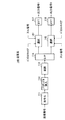
図22に、端末送信系230から送信されたOFDM信号を受信復調する無線基地局の受信系の構成を示す。基地局受信系240では、複数のアンテナ241−1、241−2で受信したOFDM信号を受信RF部242−1、242−2、FFT243−1、243−2及び伝搬路補償部244−1、244−2を介して合成部245に入力する。合成部245では伝搬路補償後の複数の信号を合成、あるいは一方を選択する。合成或いは選択後の信号は復号化部246により復号されて受信信号とされる。
【0163】
(実施の形態12)
この実施の形態のOFDM通信装置の特徴は、干渉補償部で用いる逆行列の行列式の絶対値が小さい伝搬環境の場合は、1本のアンテナのみからOFDM信号を送信する点である。これにより、干渉補償部で用いる逆行列の行列式の絶対値が小さい伝搬環境の場合の誤り率特性を向上させることができる。
【0164】
干渉補償部での逆行列の行列式の絶対値|AD−BC|が小さい場合、演算ビット数の実効値が小さくなるため、逆行列の推定精度が劣化する。この結果、誤り率特性が劣化することになる。この実施の形態では、この点に着目して、干渉補償部の逆行列の行列式の絶対値を監視し、この値が小さい場合には、1本のアンテナのみから送信を行うようにした。
【0165】
図23に、この実施の形態に係るOFDM通信装置の送信系の構成を示す。図3との対応部分に同一符号を付して示す図23において、送信系250は、アンテナAN1から送信する出力信号1の処理系統上に選択部251が設けられていると共に、アンテナAN2から送信する出力信号2の処理系統上に選択部252が設けられている。
【0166】
選択部251には、パイロットキャリア挿入部115の出力が入力されていると共にヌル信号が入力されている。選択部252には、ヌル信号挿入部116によりヌル信号が挿入された後の送信データが入力されていると共にヌル信号が入力されている。各選択部251、252は、後述する送信相手局の受信系により形成された判定信号S10に基づいて、送信データまたはヌル信号を選択的に出力する。つまり、送信系250を有するOFDM通信装置では、図示しない受信系により通信相手局から判定信号S10を受信し、これを選択部251、252に送出するようになっている。
【0167】
図24に、送信系250を有するOFDM通信装置の送信相手であるOFDM通信装置の受信系の構成を示す。図4の受信系120との対応部分に同一符号を付して示す図24の受信系260では、係数算出部127により求められた逆行列の行列式の絶対値|AD−BC|を大小比較部261に入力する。大小比較部261では、絶対値|AD−BC|をしきい値1と比較し、当該比較結果を判定信号S10として図示しない送信系を介して、図23に示すOFDM通信装置の送信系250の選択部251、252に通知する。
【0168】
以上の構成において、先ず送信系250を有するOFDM通信装置により形成されたOFDM信号が送信系250から送信される。このOFDM信号は通信相手であるOFDM通信装置の受信系260により受信復調される。
【0169】
受信系260は、係数算出部127によって伝搬路推定部123、125により得られた伝搬路特性A、B、C、Dを用いて、伝搬路補償及び干渉補償するための係数A/(AD−BC)、B/(AD−BC)、C/(AD−BC)、D/(AD−BC)を求める。大小比較部261は、係数算出部127により求められた逆行列の行列式の絶対値|AD−BC|をしきい値1と比較し、当該比較結果を判定信号S10として送信系250を有するOFDM通信装置に送信する。
【0170】
そして、この判定信号S10を受信したOFDM通信装置は、当該判定信号S10を選択部251、252に入力させる。選択部251、252は、絶対値|AD−BC|がしきい値1以上の場合には、パイロットキャリア挿入部115、ヌル信号挿入部116の信号を選択出力する。これに対して、選択部251、252は、絶対値|AD−BC|がしきい値1未満の場合には、いずれか一方の選択部251又は252がヌル信号を選択出力する。例えば選択部251がパイロットキャリア挿入部115からの信号を選択出力する場合には、選択部252がヌル信号を出力するようになっている。
【0171】
このように、絶対値|AD−BC|が大きく、通信相手側で伝搬路補償及び干渉補償の精度を維持できるときには、複数のアンテナからそれぞれ異なる送信データを重畳したOFDM信号を送信する。これに対して、絶対値|AD−BC|が小さく、通信相手側で伝搬路補償及び干渉補償の精度が劣化してしまうときには、1本のアンテナからのみOFDM信号を送信する。この結果、補償精度が悪くても、伝搬路上での干渉が格段に低減されるので、通信相手側では誤り率特性の良い受信信号を得ることができる。
【0172】
以上の構成によれば、伝搬路補償及び干渉補償するための逆行列の係数(AD−BC)が小さい場合には、1本のアンテナのみからOFDM信号を送信するようにしたことにより、伝搬路補償及び干渉補償の補償精度の悪い伝搬環境下での誤り率特性の劣化を抑制することができる。
【0173】
因みに、この実施の形態は、互いのOFDM通信装置がアクセス方式としてFDD(Frequency Division Duplex)方式を用いて通信を行う場合に特に有効である。つまり、この実施の形態では、送信系250によりある周波数帯域で送信したOFDM信号の伝搬路特性を受信側で推定し、その推定結果(判定信号S10)を送信系250を有するOFDM通信装置に通知し、送信系250はその判定信号S10を反映したOFDM信号を形成する。これにより、下り回線と上り回線の伝搬特性が異なるFDD方式において、送信系250が的確な判定結果S10に基づいて、上述した伝搬路環境に応じたOFDM信号を形成できるようになる。
【0174】
因みにアクセス方式としてTDD(Time Division Duplex)方式を用いる場合に有効な構成は、次の実施の形態13で説明する。
【0175】
(実施の形態13)
この実施の形態のOFDM通信装置の特徴は、上述した実施の形態12と比較して、受信時の逆行列の行列式の絶対値|AD−BC|の判定結果を送信時に反映するようにした点である。これにより、この実施の形態のOFDM通信装置は、上り回線と下り回線の伝搬特性が同じTDD方式において、制御情報(判定結果信号)の伝送を削減し得る分だけ、伝送効率を向上させて実施の形態12と同様の効果を得ることができる。
【0176】
図23及び図24との対応部分に同一符号を付して示す図25において、この実施の形態のOFDM通信装置270は、送信系280及び受信系290を有する。これによりOFDM通信装置270では、受信系290で得た判定結果S10を送信系280に反映できるようになっている。
【0177】
以上の構成によれば、受信系290により得られる伝搬路補償及び干渉補償するための逆行列の行列式の絶対値|AD−BC|をしきい値判定し、この判定結果を、同一のOFDM通信装置の送信系270に反映して、逆行列の行列式の絶対値|AD−BC|がしきい値よりも小さい場合には、1本のアンテナのみからOFDM信号を送信するようにしたことにより、通信相手側に制御情報(判定結果S10)を送信することなしに、伝搬路補償及び干渉補償の補償精度の悪い伝搬環境下での誤り率特性の劣化を抑制することができる。
【0178】
(実施の形態14)
この実施の形態の特徴は、実施の形態12や実施の形態13と比較して、干渉補償部の逆行列の行列式の絶対値の大きさの判定に使用するしきい値を可変とした点である。これにより、干渉補償部で用いる逆行列の行列式の絶対値が小さくなるような伝搬環境の場合の誤り率特性の劣化を一段と抑制することができる。
【0179】
本願の発明者らは、干渉補償部で用いる逆行列の行列式の絶対値の大きさを比較する比較部でのしきい値の最適値は、受信したOFDM信号の回線品質によって異なることに着目した。つまり、回線品質が悪い場合には、逆行列の行列式の絶対値|AD−BC|の検出誤差は大きくなるので、回線品質が悪い場合には、比較部でのしきい値を大きい値にする。
【0180】
図24との対応部分に同一符号を付して示す図26において、この実施の形態の受信系300は、大小比較部261がしきい値判定に用いるしきい値を選択する選択部301を有する点を除いて、図24の受信系260と同様の構成でなる。
【0181】
選択部301は、例えばCRC(Cyclic Redundancy Check)やRSSI(Received Signal Strength Indicator)信号等の受信品質情報に基づいてそれぞれ値の異なるしきい値1かしきい値2(しきい値1<しきい値2とする)のいずれかを選択出力する。実際上、受信品質情報が受信品質が良いことを示すものであった場合にはしきい値1を選択出力し、悪いことを示すものであった場合にはしきい値1よりも値の大きいしきい値2を選択出力する。
【0182】
大小比較部261は、このようにして受信品質により変更されたしきい値を用いて、伝搬路干渉・干渉補償部124、126で用いる逆行列の行列式の絶対値|AD−BC|の大きさをしきい値判定する。
【0183】
この結果、受信系300の大小比較部261からは、受信品質が悪い場合には、実施の形態12や実施の形態13で説明した送信系260、280に対して、実施の形態12や実施の形態13よりも、1本のアンテナのみからOFDM信号を送信する方向に送信系260、280を制御する判定信号S20が出力されるようになる。
【0184】
以上の構成によれば、伝搬路補償及び干渉補償するための逆行列の行列式の絶対値が小さい場合には、1本のアンテナのみからOFDM信号を送信することに加えて、受信品質に応じて前記逆行列の行列式の絶対値の大小を比較するしきい値を変えるようにしたことにより、実施の形態12や実施の形態13と比較して、前記逆行列の行列式の絶対値が小さくなるような伝搬環境での誤り率特性をさらに向上させることができる。
【0185】
(実施の形態15)
この実施の形態の特徴は、実施の形態12や実施の形態13と比較して、干渉補償部で用いる逆行列の行列式の絶対値が小さいサブキャリアが多い伝搬環境の場合に、1本のアンテナのみからOFDM信号を送信するようにした点である。これにより、実施の形態12や実施の形態13と比較して、伝送効率の低下を抑えた状態で、一段と誤り率特性を向上させることができる。
【0186】
本願の発明者らは、干渉補償部で用いる逆行列の行列式の絶対値が小さいサブキャリアが少ない場合(例えば全サブキャリア数48個のうち、3サブキャリアのみがしきい値を下回ったような場合)には、復号化部での誤り率訂正効果により誤り率特性を改善できるので、複数のアンテナからOFDM信号を送信しても問題ないと考えた。これに対して、干渉補償部で用いる逆行列の行列式の絶対値が小さいサブキャリアが多い場合には、復号化部での誤り率訂正効果がそれほど期待できないので、1本のアンテナのみからOFDM信号を送信することで、誤り率特性を向上させるようにした。
【0187】
図24との対応部分に同一符号を付して示す図27において、この実施の形態の受信系310は、大小比較部261の比較結果をカウントするカウンタ311とカウンタ311のカウント値をしきい値判定する大小比較部312を有することを除いて、図24の受信系260と同様の構成でなる。
【0188】
カウンタ311は、大小比較部261からの判定信号S10に基づいて、絶対値|AD−BC|がしきい値1を下回るサブキャリア数をカウントする。大小比較部312は、カウント値としきい値3とを比較し、カウント値がしきい値3を上回ったときに、実施の形態12や実施の形態13で説明した送信系260、280に、1本のアンテナのみからOFDM信号を送信することを指示する判定信号S30を送出する。
【0189】
以上の構成によれば、干渉補償部で用いる逆行列の行列式の絶対値が小さいサブキャリアの数を考慮して、1本のアンテナのみからOFDM信号を送信するか否かを選択するようにしたことにより、実施の形態12や実施の形態13よりさらに誤り率特性の向上と伝送効率とを両立させることができる。
【0190】
(実施の形態16)
この実施の形態の特徴は、実施の形態15と比較して、干渉補償部で用いる逆行列の行列式の絶対値が小さいサブキャリアが連続するような伝搬環境の場合に、1本のアンテナのみからOFDM信号を送信するようにした点である。これにより、実施の形態15よりもさらに伝搬効率の低下を抑えた状態で、一段と誤り率特性を向上させることができる。
【0191】
本願の発明者らは、品質の悪いデータが集中すると、誤り訂正の効果が低下し、誤り率特性が低下する点に着目した。そしてこれを考慮して、干渉補償部で用いる逆行列の行列式の絶対値が小さいサブキャリアが連続するような伝搬環境の場合に、つまり品質の悪いデータが集中する場合に、1本のアンテナのみからOFDM信号を送信することで、誤り率特性を向上させるようにした。
【0192】
図27との対応部分に同一符号を付して示す図28において、この実施の形態の受信系320は、図27のカウンタ311と大小比較部312に替えて、カウント値のインクリメントとディクリメントの両方を行うカウンタ321と、カウント値としきい値4との大小を比較する大小比較部322とを設けた点を除いて、図27の受信系310と同様の構成でなる。
【0193】
カウンタ321は、大小比較部261からの判定信号S10に基づいて、逆行列の行列式の絶対値|AD−BC|がしきい値1を下回るサブキャリアの集中度をカウントする。つまり、絶対値がしきい値1を下回ったときにはカウント値をインクリメントし、しきい値1以上の場合にはカウント値をディクリメントする。
【0194】
大小比較部322は、カウント値としきい値4とを比較し、カウント値がしきい値4を上回ったとき、つまり絶対値|AD−BC|がしきい値1を下回るサブキャリアの集中度がある一定値より大きくなったときに、実施の形態12や実施の形態13で説明した送信系260、280に、1本のアンテナのみからOFDM信号を送信することを指示する判定信号S40を送出する。
【0195】
以上の構成によれば、逆行列の行列式の絶対値|AD−BC|が所定のしきい値を下回るサブキャリアの集中度を考慮して、1本のアンテナのみからOFDM信号を送信するか否かを選択するようにしたことにより、実施の形態15よりさらに誤り率特性の向上と伝送効率とを両立させることができる。
【0196】
(実施の形態17)
この実施の形態の特徴は、実施の形態16と比較して、逆行列の行列式の絶対値|AD−BC|が所定のしきい値を下回るサブキャリアの集中度を判定するしきい値を受信品質に応じて可変とした点である。これにより、実施の形態16よりもさらに伝搬効率の低下を抑えた状態で、一段と誤り率特性を向上させることができる。
【0197】
図28との対応部分に同一符号を付して示す図29において、この実施の形態の受信系330は、大小比較部322がしきい値判定に用いるしきい値を選択する選択部331を有する点を除いて、図28の受信系320と同様の構成でなる。
【0198】
選択部331は、例えばCRC(Cyclic Redundancy Check)やRSSI(Received Signal Strength Indicator)信号等の受信品質情報に基づいてそれぞれ値の異なるしきい値4かしきい値5(しきい値4<しきい値5とする)のいずれかを選択出力する。実際上、受信品質情報が受信品質が良いことを示すものであった場合にはしきい値5を選択出力し、悪いことを示すものであった場合にはしきい値5よりも値の小さいしきい値4を選択出力する。
【0199】
大小比較部322は、このようにして受信品質により変更されたしきい値を用いて、逆行列の行列式の絶対値|AD−BC|が所定のしきい値を下回るサブキャリアの集中度をしきい値判定する。
【0200】
このようにして、受信系330の大小比較部322からは、受信品質が悪い場合には、実施の形態12や実施の形態13で説明した送信系260、280に対して、絶対値|AD−BC|が所定のしきい値を下回るサブキャリアの集中度が小さくても、1本のアンテナのみからOFDM信号を送信する方向に送信系260、280を制御する判定信号S50が出力される。
【0201】
以上の構成によれば、逆行列の行列式の絶対値|AD−BC|が所定のしきい値を下回るサブキャリアの集中度と受信品質とを加味して、1本のアンテナのみからOFDM信号を送信するか否かを選択するようにしたことにより、実施の形態16よりさらに誤り率特性の向上と伝送効率とを両立させることができる。
【0202】
(実施の形態18)
この実施の形態の特徴は、最後のデータ群は1本のアンテナのみからOFDM信号を送信することにより、受信を終了してから送信を開始するまでの時間を短縮できるようにした点である。
【0203】
ここでMMAC(Multimedia Mobile Access Communication)のHiSAN(High Speed Wireless Access Network)のように、受信終了から送信開始までの時間が規定されている場合がある。受信系の干渉補償回路は通常の同期検波回路より処理遅延が大きいため、上記受信を終了してから送信を開始するまでの時間の規格を満足できない場合もある。
【0204】
これを考慮して、この実施の形態では、最後のデータ群は1本のアンテナのみからOFDM信号として送信することにより、最後のデータ群の処理遅延を短縮し、これにより受信を終了してから送信を開始するまでの時間を短縮するようにした。
【0205】
図30に、この実施の形態の送信系340の構成を示す。図3との対応部分に同一符号を付して示す図30において、送信系340は、アンテナAN1から送信する出力信号1の処理系統上に選択部341が設けられていると共に、アンテナAN2から送信する出力信号2の処理系統上に選択部342が設けられている。
【0206】
選択部341には、パイロットキャリア挿入部の出力が入力されていると共にヌル信号が入力されている。選択部342には、ヌル信号挿入部116によりヌル信号が挿入された後の送信データが入力されていると共にヌル信号が入力されている。各選択部341、342は、最後のバーストを示す信号に基づいて、送信データまたはヌル信号を選択的に出力する。
【0207】
具体的には、最後のバーストを示す信号が入力されないときには、選択部341がパイロットキャリア挿入部115からの信号を出力すると共に、選択部342がヌル信号挿入部116からの信号を出力する。これに対して、最後のバーストを示す信号が入力された場合には、選択部341又は選択部342のいずれか一方がヌル信号を選択出力する。これにより、最後のデータ群を1本のアンテナのみからOFDM信号として送信することができる。
【0208】
(実施の形態19)
この実施の形態の特徴は、端末同士が通信する時間帯においては、基地局からはその通信端末に対して1本のアンテナからのみOFDM信号を送信するようにした点である。
【0209】
図31に示すOFDM通信システム350のように、システムによっては、端末同士が通信する場合もある。このような場合、端末同士が通信する時間帯を確保する必要があり、制御が複雑になる。これを考慮して、この実施の形態では、端末同士が通信する時間帯においては、基地局からは端末1に対して1本のアンテナからのみOFDM信号を送信する。これにより、端末1では、基地局から送信されたデータと他端末2から送信されたデータの両方を受信できるので、端末同士が通信する時間帯を複雑な制御により確保する必要が無くなる。
【0210】
図32に、この実施の形態の送信系の構成を示す。送信系360は図31の無線基地局に設けられている。図30との対応部分に同一符号を付して示す図32において、送信系360は、選択部361、362に、端末1(図31)が他端末2からの信号を受信するタイミングを示す情報を入力する点を除いて、図30の送信系340と同様の構成でなる。
【0211】
送信系360は、端末1が端末2からの信号を受信するタイミングでないときには、選択部361がパイロットキャリア挿入部115からの信号を出力すると共に、選択部362がヌル信号挿入部116からの信号を出力する。これに対して、端末1が端末2からの信号を受信するタイミングのときには、選択部361又は選択部362のいずれか一方がヌル信号を選択出力する。
【0212】
これにより、端末が他端末からの信号を受信するタイミングのときに、1本のアンテナのみからOFDM信号を送信することができる。この結果、端末では他端末の通信を確保しながら基地局からのOFDM信号を受信することができる。
【0213】
(実施の形態20)
この実施の形態の特徴は、1本のアンテナのみからOFDM信号を送信するといった処理を周期的に行うことで、受信側において伝搬路推定結果を周期的に更新(以下これを伝搬路トラッキングと呼ぶ)できるようにした点である。これにより、伝搬路推定用プリアンブルの間隔に対して伝搬路変動が速い場合の誤り率特性の劣化を抑制することができる。
【0214】
ここで伝搬路推定用プリアンブルの間隔に対して伝搬路変動が速い場合、誤り率特性の劣化が大きくなる。このような場合、伝搬路トラッキングが公知の技術としてあるが、この実施の形態のように複数のアンテナから異なるOFDM信号を送信するフレームフォーマットでは、伝搬路トラッキングを行うことが困難となる。
【0215】
これを考慮して、この実施の形態では、1本のアンテナのみからOFDM信号を送信する処理を周期的に行い、受信側ではこの1本のアンテナから送信されたOFDM信号を用いて伝搬路トラッキングを行うようにする。この結果、伝搬路推定用プリアンブルの間隔に対して伝搬路変動が速い場合の誤り率特性の劣化を抑制できる。
【0216】
図33に、この実施の形態の送信系の構成を示す。図32との対応部分に同一符号を付して示す図33において、送信系370は、自走式のカウンタ371のカウント値を大小比較部372に入力する。大小比較部372はカウント値としきい値1とを比較し、カウント値がしきい値よりも大きくなったときにこれを示す判定信号を選択部373、374及びカウンタ371に送出する。
【0217】
選択部373、374では、カウント値がしきい値よりも大きくなったことを示す判定信号が入力されたときに、いずれか一方の選択部373又は375がヌル信号を選択的に出力することにより、1本のアンテナのみからOFDM信号を送信する。またカウンタ371では、カウント値がしきい値よりも大きくなったことを示す判定信号が入力されると、一旦カウント値をリセットし、再び自走によりカウント値をインクリメントする。
【0218】
これにより、カウント値がしきい値よりも大きくなったことを示す判定信号が周期的に得られ、1本のアンテナのみからOFDM信号を送信するといった処理を周期的に行うことができる。
【0219】
図34に、送信系370から送信されたOFDM信号を受信復調する受信系の構成を示す。図4との対応部分に同一符号を付して示す図34において、受信系380は、各アンテナで受信したOFDM信号(入力信号1、入力信号2)に対して伝搬路トラッキング処理を行う伝搬路トラッキング部381、382を有すると共に、当該伝搬路トラッキング部381、382にローカルエンコードした信号を供給する再符号化・再変調部385及びシリアルパラレル変換部(S/P)を有することを除いて、図4の受信系120と同様の構成でなる。
【0220】
再符号化・再変調部385は、復号後の受信信号に対して送信側と同じ符号化及び変調処理を行うことにより受信信号をローカルエンコードし、これをS/P386により送信データ1と送信データ2に分流した後、対応する系統の伝搬路トラッキング部381、382に送出する。
【0221】
ここで図35に、伝搬路トラッキング部381、382の構成を示す。この伝搬路トラッキング処理は、公知の技術なので簡単に説明する。伝搬路トラッキング部381(382)は、乗算器391によって再変調後の信号とFFT出力信号を乗算する。乗算後の信号は、乗算器392により値1−uが乗じられて加算器393に送出される。加算器393では、メモリ395に格納された加算結果に乗算器394で値uが乗じられたものと、乗算器392の乗算結果とが加算される。そしてこの加算結果がメモリ395に格納される。そしてメモリ395に格納されている加算値がトラッキング後の伝搬路推定結果として、図34の伝搬路推定部383、384に送出される。
【0222】
以上の構成によれば、1本のアンテナのみからOFDM信号を送信するといった処理を周期的に行うようにしたことにより、伝搬路変動が速い場合の誤り率特性の劣化を抑制することができる。
【0223】
(実施の形態21)
この実施の形態の特徴は、実施の形態20と比較して、1本のアンテナのみからOFDM信号を送信するといった処理を周期的に行うと共に、この周期を可変とした点である。これにより、実施の形態20と比較して、伝搬効率の低下を有効に抑制しながら、誤り率特性の劣化を抑制できる。
【0224】
1本のアンテナのみ送信する周期は可変とした方が、伝送効率と誤り率特性を両立させることができる。例えば、情報をできるだけ多く送信したい場合は、1本のアンテナのみ送信する周期を長くした方がよい。しかし、十分な誤り率特性を得たい場合は、1本のアンテナのみ送信する周期を短くした方がよい。例えば、他のバーストより多くのデータを送りたい場合には、1本のアンテナのみ送信する周期を長くする。
【0225】
図36に、この実施の形態の送信系の構成を示す。図33との対応部分に同一符号を付して示す図36において、この実施の形態の送信系400は、大小比較部402でのしきい値を選択する選択部401を有することを除いて、図36の送信系390と同様の構成でなる。
【0226】
選択部401は、CRCやRSSI信号等の受信品質情報に基づいてそれぞれ値の異なるしきい値1かしきい値2(しきい値1<しきい値2とする)のいずれかを選択出力する。この受信品質情報は、FDD方式の通信を行っている場合には通信相手により得られたものを用い、TDD方式の通信を行っている場合には自局で得られたものを用いることが好ましい。
【0227】
選択部401は受信品質が良い場合にはしきい値2を選択出力し、悪いことを示すものであった場合にはしきい値2よりも値の小さいしきい値1を選択出力する。この結果、送信系400では、受信品質が悪いほど1本のアンテナのみからOFDM信号を送信する周期として短い周期が設定される。このとき受信側では、伝搬路トラッキング処理を高精度で行うことができるようになるので、受信品質を向上させることができる。
【0228】
以上の構成によれば、1本のアンテナのみからOFDM信号を送信するといった処理を周期的に行うと共に、この周期を可変としたことにより、実施の形態20よりも一段と伝送効率と誤り率特性を両立させることができる。
【0229】
なおこの実施の形態では、周期を可変とする条件として、要求される送信データ量や受信品質を挙げたが、この条件はこれに限らない。例えば伝搬路変動速度を推定(例えば前回のバーストとの伝搬路推定結果の差がしきい値を超えたら伝搬路の変動が速いとみなす)し、この変動速度がしきい値を超えたら、周期を短くするといった方法がある。
【0230】
(実施の形態22)
この実施の形態の特徴は、複数のアンテナ(例えばマルチセクタアンテナ)を使用する場合、どのアンテナを使用しても干渉補償部で用いる逆行列の行列式の絶対値が小さくなるような伝搬環境の場合は、1本のアンテナのみからOFDM信号を送信するようにした点である。これにより伝送効率と誤り率特性の両立を図ることができる。
【0231】
マルチセクタアンテナのように複数のアンテナを使用する場合、セクタを変えることによって、複数のアンテナから異なるデータを同時に送信しても誤り率特性が劣化しない伝搬環境にすることも可能である。
【0232】
この実施の形態では、この点に着目して、マルチセクタアンテナのように複数のアンテナを使用する場合、どのアンテナを選択しても干渉補償部で用いる逆行列の行列式の絶対値が小さい伝搬環境のときだけ、1本のアンテナのみからOFDM信号を送信する。
【0233】
図37に、この実施の形態の受信系の構成を示す。図28との対応部分に同一符号を付して示す図37において、受信系410はマルチセクタアンテナ413−1、413−2、414−1、414−2を有すると共に、当該マルチセクタアンテナ413−1、413−2、414−1、414−2のうち所定のアンテナを選択する選択部411、412を有する。
【0234】
選択部411、412は、大小比較部261からの判定信号S10に基づいて受信アンテナを選択する。例えば最初に選択部411がアンテナ413−1を選択しかつ選択部412がアンテナ414−1を選択して、これらのアンテナからの受信信号に基づいて受信信号を受信復調する。このとき大小比較部261により、絶対値|AD−BC|がしきい値1を下回っていることを示す判定結果S10が得られると、選択部411が受信アンテナをアンテナ413−2に切り替えると共に選択部412が受信アンテナをアンテナ414−2に切り替える。
【0235】
受信系410は、このように受信アンテナを切り替えても相変わらず、大小比較部261により、絶対値|AD−BC|がしきい値1を下回っていることを示す判定結果S10が得られると、大小比較部322から送信系に対して、1本のアンテナのみからOFDM信号を送信することを指示する判定信号S40を送出する。因みに、図37の場合には大小比較部322のしきい値4は「1」に設定されており、カウンタ321のカウント値が「2」となったとき、1本のアンテナのみからOFDM信号を送信することを指示する判定信号S40を送出するようになっている。
【0236】
以上の構成によれば、複数のアンテナを使用する場合、どのアンテナを選択しても干渉補償部で用いる逆行列の行列式の絶対値が小さい伝搬環境のときだけ、1本のアンテナのみからOFDM信号を送信するようにしたことにより、複数アンテナを用いた場合に、伝送効率と誤り率特性の両立を図ることができる。
【0237】
なおこの実施の形態では、干渉補償部で用いる逆行列の行列式の絶対値が小さくなったときに、セクタアンテナを切り替える場合について述べたが、セクタアンテナを切り替える方法はこれに限らない。例えば干渉補償部で用いる逆行列の行列式の絶対値がしきい値を下回るサブキャリア数があるしきい値を上回ったときに、セクタアンテナを切り替えるようにしてもよい。また干渉補償部で用いる逆行列の行列式の絶対値がしきい値を下回るサブキャリア数が連続するときに、セクタアンテナを切り替えるようにしてもよい。
【0238】
また上述の実施の形態12〜17及び22では、干渉補償で用いる逆行列の行列式の絶対値を、複数のアンテナのうちいずれか1つのアンテナのみからOFDM信号を送信するか否かを判断するための基準として用いたが、本発明はこれに限らず、要は伝搬路推定精度が低い場合にいずれか1つのアンテナのみからOFDM信号を送信すればよい。
【0239】
【発明の効果】
以上説明したように、本発明によれば、複数のアンテナから同一時間に同一サブキャリアから異なるデータを送信し、特定のサブキャリアからは既知信号を送信するOFDM通信方法において、OFDM信号に適宜ヌル信号を挿入するようにしたことにより、残留位相誤差の検出精度の劣化を防ぐことができ、誤り率特性の向上したOFDM通信方法及びOFDM通信装置を実現できる。
【図面の簡単な説明】
【図1】本発明の実施の形態1に係るOFDM通信装置により形成されるOFDM信号のフレームフォーマットを示す図
【図2】実施の形態におけるOFDM通信システムの全体構成を示す図
【図3】実施の形態1におけるOFDM通信装置の送信系の構成を示すブロック図
【図4】実施の形態1におけるOFDM通信装置の受信系の構成を示すブロック図
【図5】実施の形態2のOFDM通信装置により形成されるOFDM信号のフレームフォーマットを示す図
【図6】実施の形態2におけるOFDM通信装置の送信系の構成を示すブロック図
【図7】実施の形態3のOFDM通信装置により形成されるOFDM信号のフレームフォーマットを示す図
【図8】実施の形態3におけるOFDM通信装置の送信系の構成を示すブロック図
【図9】実施の形態4のOFDM通信装置により形成されるOFDM信号のフレームフォーマットを示す図
【図10】実施の形態4におけるOFDM通信装置の送信系の構成を示すブロック図
【図11】実施の形態5のOFDM通信装置により形成されるOFDM信号のフレームフォーマットを示す図
【図12】実施の形態5におけるOFDM通信装置の送信系の構成を示すブロック図
【図13】実施の形態6のOFDM通信装置により形成されるOFDM信号のフレームフォーマットを示す図
【図14】実施の形態6におけるOFDM通信装置の送信系の構成を示すブロック図
【図15】実施の形態7のOFDM通信装置により形成されるOFDM信号のフレームフォーマットを示す図
【図16】実施の形態7におけるOFDM通信装置の送信系の構成を示すブロック図
【図17】実施の形態8におけるOFDM通信装置の受信系の構成を示すブロック図
【図18】直流オフセット除去回路の構成を示すブロック図
【図19】実施の形態9におけるOFDM通信装置の送信系の構成を示すブロック図
【図20】実施の形態10におけるOFDM通信装置の送信系の構成を示すブロック図
【図21】実施の形態11におけるOFDM通信装置の端末の送信系の構成を示すブロック図
【図22】実施の形態11におけるOFDM通信装置の受信系の構成を示すブロック図
【図23】実施の形態12におけるOFDM通信装置の送信系の構成を示すブロック図
【図24】実施の形態12におけるOFDM通信装置の受信系の構成を示すブロック図
【図25】実施の形態13におけるOFDM通信装置の構成を示すブロック図
【図26】実施の形態14におけるOFDM通信装置の受信系の構成を示すブロック図
【図27】実施の形態15におけるOFDM通信装置の受信系の構成を示すブロック図
【図28】実施の形態16におけるOFDM通信装置の受信系の構成を示すブロック図
【図29】実施の形態17におけるOFDM通信装置の受信系の構成を示すブロック図
【図30】実施の形態18におけるOFDM通信装置の送信系の構成を示すブロック図
【図31】実施の形態19におけるOFDM通信システムの全体構成を示す概略図
【図32】実施の形態19におけるOFDM通信装置の送信系の構成を示すブロック図
【図33】実施の形態20におけるOFDM通信装置の送信系の構成を示すブロック図
【図34】実施の形態20におけるOFDM通信装置の受信系の構成を示すブロック図
【図35】伝搬路トラッキング部の構成を示すブロック図
【図36】実施の形態21におけるOFDM通信装置の送信系の構成を示すブロック図
【図37】実施の形態22におけるOFDM通信装置の受信系の構成を示すブロック図
【図38】OFDM信号におけるパイロットシンボルの配置例を示す図
【図39】伝搬路推定の説明に供するOFDM通信システムの全体構成を示す図
【図40】OFDM信号の一般的なフレームフォーマットを示す図
【図41】従来のOFDM通信装置の送信系の構成を示すブロック図
【図42】従来のOFDM通信装置の受信系の構成を示すブロック図
【図43】係数算出部の構成を示すブロック図
【符号の説明】
101、102、270 OFDM通信装置
110、140、150、160、170、180、190、210、220、230、250、280、340、360、370、400 送信系
111、161、211 符号化部
112、162、212 プリアンブル挿入部
113、213 変調部
114、165、223 シリアルパラレル変換部(S/P)
115、151、154 パイロットキャリア挿入部
116、152、153、171、191 ヌル信号挿入部
117、118 逆高速フーリエ変換部(IFFT)
120、200、240、260、290、300、310、320、330、380、410 受信系
121、122 高速フーリエ変換部(FFT)
123、125、383、384 伝搬路推定部
124、126 伝搬路補償・干渉補償部
127 係数算出部
128、129、141、142、181、182、214、215、221、222、251、252、301、331、341、342、361、362、373、374、401、411、412 選択部
130 残留位相誤差検出部
131、132 位相補償部
133、164 パラレルシリアル変換部(P/S)
134 復号化部
201、202 直流オフセット除去回路(DC除去)
261、312、322、372、402 大小比較部
311、321、371 カウンタ
350 OFDM通信システム
381、382 伝搬路トラッキング部
A、B、C、D 伝搬路特性
TX1、TX2 送信信号
RX1、RX2 受信信号
AN1〜AN4、413−1、413−2、414−1、414−2 アンテナ
S10、S20、S30、S40、S50 判定信号[0001]
BACKGROUND OF THE INVENTION
The present invention relates to an OFDM (Orthogonal Frequency Division Multiplexing) communication method and apparatus therefor, and is particularly suitable for application to a case where a plurality of OFDM signals on which different data are superimposed are transmitted using a plurality of antennas.
[0002]
[Prior art]
This type of OFDM communication method has an advantage that a large amount of data can be transmitted at high speed because a plurality of OFDM signals can be transmitted from a plurality of antennas. However, if high-accuracy propagation path compensation and interference compensation are not performed on the receiving side, the error rate characteristics of data will deteriorate.
[0003]
Therefore, in this type of OFDM communication method, as shown in FIG. 38, the transmitting side forms a pilot carrier by superimposing a known signal such as a pilot symbol on a predetermined carrier wave (hereinafter referred to as a subcarrier), On the receiving side, a received signal having a good error rate characteristic is obtained by compensating propagation path distortion such as a frequency offset of each subcarrier based on the pilot carrier.
[0004]
In the OFDM communication method, an OFDM signal in which a propagation path estimation preamble is arranged on each subcarrier is transmitted on the transmission side, and the phase rotation of each subcarrier is compensated on the reception side based on this propagation path estimation preamble. It has become.
[0005]
Next, the principle of transmission / reception of the OFDM communication apparatus will be described with reference to FIG. FIG. 39 illustrates a case where an OFDM signal is transmitted from an OFDM communication apparatus (TX) 1 having two antennas AN1 and AN2 to an OFDM communication apparatus (RX) 2 having two antennas AN3 and AN4. Here, signals transmitted from the antennas AN1 and AN2 of the
[0006]
RX1 = ATX1 + BTX2 (1)
RX2 = CTX1 + DTX2 (2)
In Equations (1) and (2), A is a propagation path characteristic between the transmission antenna AN1 and the reception antenna AN3, B is a propagation path characteristic between the transmission antenna AN2 and the reception antenna AN3, and C is a transmission. A propagation path characteristic between the antenna AN1 and the reception antenna AN4, and A represents a propagation path characteristic between the transmission antenna AN2 and the reception antenna AN4.
[0007]
FIG. 40 shows a frame format of an OFDM transmission signal transmitted from the
[0008]
Here, in order to receive and demodulate the transmission signals TX1 and TX2 described above from the received signal, it is necessary to estimate the four propagation path characteristics A, B, C, and D. Therefore, the
[0009]
The four propagation path characteristics A to D can be estimated as follows in the OFDM communication apparatus 2 (FIG. 39). The propagation path characteristic A is obtained by receiving a propagation path estimation preamble transmitted from the antenna AN1 by the antenna AN3 and using a signal processing unit corresponding to the antenna AN3. The characteristic B is obtained by the propagation path estimation preamble transmitted from the antenna AN2 by the antenna AN3 and obtained by a signal processing unit corresponding to the antenna AN3. The characteristic C is obtained by receiving a propagation path estimation preamble transmitted from the antenna AN1 by the antenna AN4 and using a signal processing unit corresponding to the antenna AN4. The propagation path estimation preamble transmitted from the characteristic AD antenna AN2 is received by the antenna AN4 and obtained by a signal processing unit corresponding to the antenna AN4.
[0010]
Next, the
[0011]
DRX1 / (AD-BC)-BRX2 / (AD-BC)
= D (ATX1 + BTX2) / (AD-BC)-B (DTX1 + DTX2) / (AD-BC)
= (ADTX1 + BDTX2-BCTX1-BDTX2) / (AD-BC)
= TX1 (3)
−CRX1 / (AD-BC)-ARX2 / (AD-BC)
= -C (ATX1 + BTX2) / (AD-BC) + A (CTX1 + DTX2) / (AD-BC)
= (-ACTX1-BCTX2 + ACTX1-ADTX2) / (AD-BC)
= TX2 ……… (4)
In practice, the propagation path estimation preamble is transmitted as follows. That is, during the time when the propagation path estimation preamble is transmitted from the antenna AN1, the propagation path estimation preamble is not transmitted from the antenna AN2. Similarly, during the time when the propagation path estimation preamble is transmitted from the antenna AN2, the propagation path estimation preamble is not transmitted from the antenna AN2.
[0012]
In general, the pilot carrier is used to compensate a residual phase error due to a frequency offset detection error or the like. That is, at the time of reception, a residual phase error is detected and compensated using a known signal (pilot signal) superimposed on a pilot carrier. Actually, as shown in FIG. 40, a specific subcarrier is transmitted as a pilot carrier. In the example shown in FIG. 40, among the 2k + 1 subcarriers, four subcarriers of antenna AN1 are transmitted as pilot carriers.
[0013]
FIG. 41 shows the configuration of the transmission system of the
[0014]
The signal subjected to the modulation processing by the
[0015]
FIG. 42 shows the configuration of the reception system of OFDM communication apparatus 2 (FIG. 39). In the
[0016]
The
[0017]
The propagation
[0018]
The
[0019]
Returning to FIG. 42, the propagation path compensation /
[0020]
The reception signal TX1 after propagation path compensation / interference compensation is sent to the residual phase
[0021]
The
[0022]
[Problems to be solved by the invention]
However, in the conventional OFDM communication apparatus, as can be seen from FIG. 40, the data transmitted from the other antenna is superimposed on the known signal (pilot carrier) transmitted from one antenna as interference. For this reason, in order to detect the residual phase error, it is necessary to remove the interference component superimposed on the known signal.
[0023]
However, when there are intersymbol interference, timing error, frequency offset detection error, and the like due to multipath, the interference cancellation characteristics deteriorate. As a result, since the interference signal remains in the known signal, there is a problem that the error rate characteristic is greatly deteriorated.
[0024]
The present invention has been made in view of the above points, and an object of the present invention is to provide an OFDM communication method and an OFDM communication apparatus with improved error rate characteristics by preventing deterioration in detection accuracy of residual phase errors.
[0025]
[Means for Solving the Problems]
In order to solve this problem, the present invention employs the following method and configuration.
[0026]
(1) The OFDM communication method of the present invention is an OFDM communication method for transmitting an OFDM signal in which different data is superimposed from a plurality of antennas, and transmitting a known signal by a specific subcarrier of the OFDM signal, The known signal is transmitted from only one of the plurality of antennas, and a null signal is transmitted from an antenna other than the antenna using a subcarrier in a frequency band corresponding to the subcarrier transmitting the known signal.
[0027]
According to this method, interference of a known signal on the propagation path can be prevented, so that a highly accurate residual phase error can be detected on the receiving side. As a result, a received signal with improved error rate characteristics can be obtained.
[0028]
(2) In the OFDM communication method of the present invention, in (1), an antenna that transmits a known signal is switched among a plurality of antennas.
[0029]
According to this method, in addition to the effect of (1), it is possible to prevent the deterioration of the residual phase error detection accuracy over a long time when the line fluctuation is slow.
[0030]
(3) The OFDM communication method of the present invention is an OFDM communication method for transmitting a known signal using a specific subcarrier of the OFDM signal while transmitting an OFDM signal in which different data is superimposed from a plurality of antennas, A known signal is transmitted by subcarriers having different frequency bands of a plurality of antennas, and a null signal is transmitted by a subcarrier in another antenna corresponding to a subcarrier in which the known signal is transmitted in a certain antenna.
[0031]
According to this method, it is possible to prevent interference on the propagation path of a known signal, so that it is possible to detect a highly accurate residual phase error and obtain a received signal with improved error rate characteristics. The peak voltage of the OFDM signal transmitted from each antenna can be reduced.
[0032]
(4) In the OFDM communication method of the present invention, in (1) to (3), for a specific subcarrier, data is transmitted from only one of a plurality of antennas, and from an antenna other than the antenna. Transmits a null signal on a subcarrier in a frequency band corresponding to the subcarrier transmitting the data.
[0033]
According to this method, in addition to the effects of (1) to (3), data transmitted by a specific subcarrier is not subject to interference from corresponding subcarriers of other OFDM signals. It is possible to improve the error rate characteristics.
[0034]
(5) In the OFDM communication method of the present invention, in (4), the specific subcarrier is a subcarrier away from the center frequency of the OFDM signal.
[0035]
According to this method, it is possible to improve the error rate characteristics of data transmitted by subcarriers away from the center frequency, which are easily affected by the adjacent channel interference wave, the amplitude deviation and the group delay deviation of the analog filter.
[0036]
(6) In the OFDM communication method of the present invention, in (4) or (5), an antenna that transmits data on a specific subcarrier is switched among a plurality of antennas.
[0037]
According to this method, in addition to the effects of (4) and (5), the peak voltage can be reduced, and when the line fluctuation is very slow, the reception level of a specific subcarrier remains depressed. Can be prevented.
[0038]
(7) In the OFDM communication method of the present invention, in (1) to (6), data is transmitted from only one antenna for the subcarrier at the DC point, and a null signal is transmitted from the other antenna.
[0039]
According to this method, in addition to the effects of (1) to (6), transmission is performed by a DC point subcarrier whose error rate characteristics are likely to deteriorate compared to other subcarriers due to the DC offset of the analog circuit. Data is not subject to interference from corresponding subcarriers of other OFDM signals, so that it is possible to improve the error rate characteristics of data transmitted by the subcarriers.
[0040]
(8) In the OFDM communication method of the present invention, in (1) to (3), a specific burst signal is transmitted from only one antenna, and while transmitting this burst signal, nulls are transmitted from other antennas. Send a signal.
[0041]
According to this method, in addition to the effects of (1) to (3), the specific burst signal is not affected at all by the transmission signals from other antennas on the propagation path. The error rate characteristics on the side are improved. As a result, it is possible to further improve the error rate characteristic of only a specific burst signal, and to realize diverse wireless communication.
[0042]
(9) In the OFDM communication method of the present invention, in (8), the specific burst signal is divided into a plurality of parts, and the antenna for transmitting the divided burst signal is switched.
[0043]
According to this method, in addition to the effect of (8), since the number of transmission subcarriers of one antenna can be reduced, the peak power can be reduced accordingly.
[0044]
(10) In the OFDM communication method of the present invention, the specific burst signal of (8) is a burst signal that requires better quality than other burst signals.
[0045]
According to this method, if an important burst signal such as a burst signal for control or a burst signal for retransmission is selected as a specific burst signal, the specific burst signal is transmitted from another antenna on the propagation path. Since no interference is caused by the transmission signal, the error rate characteristic on the receiving side is improved. In addition, burst signals that require better error rate characteristics compared to other burst signals, such as control burst signals and retransmission burst signals, have a small ratio in terms of the overall burst signal, so the transmission efficiency is Almost no decline. As a result, the error rate characteristic can be further improved without significantly reducing the transmission efficiency.
[0046]
(11) In the OFDM communication method of the present invention, the OFDM communication method of (8) is applied only to uplink communication.
[0047]
According to this method, in the OFDM communication method of (8), while transmitting a specific burst signal, the transmission efficiency is reduced by the amount that a null signal is transmitted from another antenna. Considering this, in the present invention, the method (8) is used only for the uplink without using the method (8) for the downlink having a large amount of transmission data. As a result, it is possible to effectively improve the error rate characteristics of a specific burst signal transmitted through the uplink without suppressing a decrease in the throughput of the entire system and without increasing the hardware scale of the terminal station.
[0048]
(12) The OFDM communication method of the present invention includes:Apply method (8) only in a propagation environment with poor propagation path estimation accuracy..
[0049]
According to this method, it is possible to suppress deterioration of error rate characteristics in a propagation environment with poor propagation path estimation accuracy.
[0050]
(13) In the OFDM communication method of the present invention, in (12), when an OFDM signal is received, a propagation path characteristic between antennas is obtained based on a known signal superimposed on the OFDM signal, and this propagation path characteristic is obtained. The channel estimation accuracy is obtained based on the absolute value of the determinant of the inverse matrix when is expressed as a matrix component.
[0051]
According to this method, when the absolute value of the determinant of the inverse matrix is small, the effective value of the number of operation bits is small, so that the compensation accuracy in the interference compensation unit is lowered and the error rate characteristic is deteriorated. Thus, when the absolute value of the determinant of the inverse matrix is small, the OFDM signal is transmitted from only one antenna. As a result, it is possible to suppress degradation of error rate characteristics in a propagation environment where the compensation accuracy in the interference compensation unit is low.
[0052]
(14) In the OFDM communication method of the present invention, in (13), when the absolute value of the determinant of the inverse matrix is determined as a threshold value, and the absolute value of the determinant of the inverse matrix is smaller than the threshold value, The OFDM signal is transmitted from only one of the plurality of antennas, and the threshold value is changed according to the reception quality of the OFDM signal.
[0053]
According to this method, when the reception quality is bad, the detection error of the absolute value of the determinant of the inverse matrix becomes large. Therefore, when the reception quality is bad, the threshold value is set to a large value. That is, control is performed so that an OFDM signal is transmitted from only one antenna. As a result, taking the reception quality into consideration, it is possible to suppress the deterioration of the error rate characteristic more accurately and suppress the unnecessary decrease in transmission efficiency.
[0054]
(15) In the OFDM communication method of the present invention, in (13), the magnitude of the absolute value of the determinant of the inverse matrix is determined using the first threshold value, and the absolute value of the determinant of the inverse matrix is determined. When the number of subcarriers having a value smaller than the first threshold is larger than the second threshold, the OFDM signal is transmitted from only one of the plurality of antennas.
[0055]
According to this method, when there are few subcarriers in which the absolute value of the inverse matrix determinant is small, the error rate characteristic can be improved by the error rate correction effect in the decoding unit, while the absolute value of the inverse matrix determinant When there are many subcarriers, the OFDM signal is transmitted from only one antenna when there are many subcarriers in consideration that the error rate correction effect in the decoding unit cannot be expected so much. As a result, both improvement in error rate characteristics and transmission efficiency can be achieved.
[0056]
(16) In the OFDM communication method of the present invention, in (13), the magnitude of the absolute value of the determinant of the inverse matrix is determined as a threshold value, and the subcarrier whose absolute value of the determinant of the inverse matrix is smaller than the threshold value Is continuously transmitted for a predetermined number of times or more, the OFDM signal is transmitted from only one of the plurality of antennas.
[0057]
According to this method, if poor quality data is concentrated, the effect of error correction is reduced, and the error rate characteristic is reduced, so that subcarriers having a small absolute value of the determinant of the inverse matrix continue. In a simple propagation environment, that is, when subcarriers with poor quality are concentrated, an OFDM signal is transmitted from only one antenna. As a result, both improvement in error rate characteristics and transmission efficiency can be achieved.
[0058]
(17) In the OFDM communication method of the present invention, in (16), the threshold for determining whether or not subcarriers whose absolute value of the determinant of the inverse matrix is smaller than a threshold value continue for a predetermined number of times or more. The value is changed according to the reception quality of the OFDM signal.
[0059]
According to this method, in addition to the effect of (16), it is possible to control whether or not the OFDM signal is transmitted from only one antenna in consideration of the reception quality, so that further improvement in error rate characteristics and transmission efficiency can be achieved. Both can be achieved.
[0060]
(18) In the OFDM communication method of the present invention, in (1), (3), or (12), the burst signal transmitted last in a predetermined communication unit period is any one of a plurality of antennas. Only transmit as an OFDM signal.
[0061]
According to this method, considering that the interference compensation circuit on the receiving side has a larger processing delay than a normal synchronous detection circuit, the burst signal to be transmitted last is transmitted as an OFDM signal from only one antenna, Reduce the processing delay of the last burst signal. As a result, the time from the end of reception to the start of transmission can be shortened, which is very effective for a system in which this time is specified.
[0062]
(19) In the OFDM communication method of the present invention, in (1), (3) or (12), when the communication partner station is performing OFDM communication with other stations in addition to the own station, the communication partner station On the other hand, the OFDM signal is transmitted from only one of the plurality of antennas.
[0063]
According to this method, it is not necessary to secure a time zone for communication between the communication stations by complicated control.
[0064]
(20) The OFDM communication method of the present invention includes:The method (8) is performed periodically.
[0065]
According to this method, the propagation path estimation result can be periodically updated (propagation path tracking) on the receiving side, so that the error rate characteristics when the propagation path fluctuation is fast with respect to the interval of the propagation path estimation preamble are obtained. Deterioration can be suppressed.
[0066]
(21) In the OFDM communication method of the present invention, in (20), the period for transmitting the OFDM signal from only one of the plurality of antennas is set to the required transmission efficiency, the required reception quality, or the propagation path. Change according to the fluctuation speed.
[0067]
According to this method, in addition to the effect of (20), the deterioration of the error rate characteristic can be suppressed while effectively suppressing the decrease in propagation efficiency.
[0068]
(22) An OFDM communication apparatus of the present invention includes a plurality of antennas and OFDM signal forming means for forming a plurality of OFDM signals transmitted from each of the plurality of antennas by performing orthogonal frequency division multiplexing processing on each of the plurality of transmission data. A known signal inserting means for inserting a known signal into a predetermined subcarrier of each OFDM signal, and a null signal inserting means for inserting a null signal into a predetermined subcarrier of each OFDM signal, the known signal inserting means comprising: The known signal is inserted into any one of the plurality of OFDM signals, and the null signal inserting unit is configured to transmit a known signal with respect to OFDM other than the OFDM signal into which the known signal is inserted by the known signal inserting unit. A configuration is adopted in which a null signal is inserted into a subcarrier in a frequency band corresponding to the inserted subcarrier.
[0069]
According to this configuration, it is possible to prevent interference of a known signal on the propagation path, so that a highly accurate residual phase error can be detected on the receiving side. As a result, a received signal with improved error rate characteristics can be obtained.
[0070]
(23) An OFDM communication apparatus according to the present invention includes a plurality of antennas and OFDM signal forming means for forming a plurality of OFDM signals transmitted from each of the plurality of antennas by performing orthogonal frequency division multiplexing processing on the plurality of transmission data, respectively. A known signal inserting means for inserting a known signal into a predetermined subcarrier of each OFDM signal, and a null signal inserting means for inserting a null signal into a predetermined subcarrier of each OFDM signal, the known signal inserting means comprising: The known signal is inserted into subcarriers having different frequency bands from each other in a plurality of OFDM signals, and the null signal inserting means is configured to transmit other OFDM signals in a frequency band corresponding to the subcarrier in which the known signal is inserted in a certain OFDM signal. A configuration is adopted in which a null signal is inserted into a subcarrier.
[0071]
According to this configuration, interference of a known signal on the propagation path can be prevented, so that a highly accurate residual phase error can be detected on the receiving side, and a received signal with improved error rate characteristics can be obtained. In addition, the peak voltage of the OFDM signal transmitted from each antenna can be reduced.
[0072]
(24) OFDM communication of the present inventionapparatusIsIn addition to (23), means for acquiring propagation path estimation accuracy, transmission control means for transmitting an OFDM signal from only one of the plurality of antennas only in a propagation environment with poor propagation path estimation accuracy, WithTake the configuration.
[0073]
According to this configuration, it is possible to suppress the deterioration of error rate characteristics in a propagation environment with poor propagation path estimation accuracy.
[0074]
(25) The OFDM communication apparatus of the present inventionIn addition to (23), transmission control means for periodically transmitting an OFDM signal from only one of the plurality of antennas is provided.Take the configuration.
[0075]
According to this configuration, since the propagation path estimation result can be periodically updated (propagation path tracking) on the receiving side, the error rate characteristic when the propagation path fluctuation is fast with respect to the interval of the propagation path estimation preamble. Deterioration can be suppressed.
[0076]
DETAILED DESCRIPTION OF THE INVENTION
The essence of the present invention is that an OFDM signal in which different data is superimposed is transmitted from a plurality of antennas, and a known signal is transmitted by a specific subcarrier of the OFDM signal, and a null signal is appropriately inserted into the OFDM signal. This is what I did. As a result, the known signal can be prevented from receiving interference from other signals on the propagation path, so that the detection accuracy of the residual phase error can be improved and the error rate characteristic of the received signal can be improved.
[0077]
Hereinafter, embodiments of the present invention will be described in detail with reference to the drawings.
[0078]
(Embodiment 1)
FIG. 1 is a schematic diagram of an OFDM signal transmitted from the OFDM communication apparatus according to
[0079]
In this embodiment, as shown in FIGS. 1A and 1B, a specific subcarrier of one antenna is a pilot carrier on which a known signal is superimposed, and no pilot carrier is output from the other antenna. In addition, a subcarrier having the same frequency as that of the pilot carrier is set as a subcarrier on which a null signal is superimposed (that is, only a carrier on which no signal is superimposed). Thereby, since the pilot carrier does not receive interference on the propagation path, it is possible to obtain a known signal not receiving interference on the receiving side.
[0080]
Incidentally, in FIG. 1, for example, DATA1 (N, K) represents that the Nth symbol related to
[0081]
FIG. 2 shows a configuration of an OFDM communication system using the OFDM communication apparatus of the first embodiment. FIG. 2 illustrates a case where an OFDM signal is transmitted from an OFDM communication apparatus (TX) 101 having two antennas AN1 and AN2 to an OFDM communication apparatus (RX) 102 having two antennas AN3 and AN4. Here, it is assumed that signals transmitted from the antennas AN1 and AN2 are TX1 and TX2, respectively. Further, assuming that signals received by the respective antennas are RX1 and RX2, RX1 and RX2 can be expressed by the following equations, respectively.
[0082]
RX1 = ATX1 + BTX2 (5)
RX2 = CTX1 + DTX2 (6)
In Equations (5) and (6), A is a propagation path characteristic between the transmission antenna AN1 and the reception antenna AN3, B is a propagation path characteristic between the transmission antenna AN2 and the reception antenna AN3, and C is a transmission. A propagation path characteristic between the antenna AN1 and the reception antenna AN4, and A represents a propagation path characteristic between the transmission antenna AN2 and the reception antenna AN4.
[0083]
Here, in order to receive and demodulate the transmission signals TX1 and TX2 from the reception signal, it is necessary to estimate the four propagation path characteristics A, B, C, and D. Therefore, the
[0084]
The four propagation path characteristics A to D can be estimated using the propagation path estimation preamble in the
[0085]
Next, the
[0086]
DRX1 / (AD-BC)-BRX2 / (AD-BC)
= D (ATX1 + BTX2) / (AD-BC)-B (DTX1 + DTX2) / (AD-BC)
= (ADTX1 + BDTX2-BCTX1-BDTX2) / (AD-BC)
= TX1 ……… (7)
−CRX1 / (AD-BC)-ARX2 / (AD-BC)
= -C (ATX1 + BTX2) / (AD-BC) + A (CTX1 + DTX2) / (AD-BC)
= (-ACTX1-BCTX2 + ACTX1-ADTX2) / (AD-BC)
= TX2 ……… (8)
The pilot carrier is used to compensate for a residual phase error due to a frequency offset detection error or the like. That is, at the time of reception, a residual phase error is detected and compensated using a known signal superimposed on a pilot carrier.
[0087]
FIG. 3 is a block diagram illustrating a configuration of a transmission system of the
[0088]
In the case of this embodiment, the transmission signal is a signal in which two
[0089]
As described above, the
[0090]
The
[0091]
Pilot
[0092]
Each
[0093]
FIG. 4 shows the configuration of the reception system of
[0094]
The
[0095]
The propagation
[0096]
The
[0097]
The propagation path compensation /
[0098]
The coefficients obtained by the
[0099]
The reception signal TX1 after propagation path compensation / interference compensation is sent to the residual phase
[0100]
The
[0101]
In the above configuration, the
[0102]
As a result, since the known signal is not subject to data interference on the propagation path, the
[0103]
The residual phase
[0104]
According to the above configuration, when transmitting an OFDM signal from a plurality of antennas AN1 and AN2, a specific subcarrier of one antenna AN1 is a pilot carrier on which a known signal is superimposed, and a pilot carrier is transmitted from the other antenna AN2. , And the subcarrier with the same frequency as the pilot carrier is a subcarrier on which a null signal is superimposed, so that interference on the propagation path of a known signal can be prevented. Error can be detected. As a result, a received signal with improved error rate characteristics can be obtained.
[0105]
In the above-described embodiment, the case where two OFDM signals are transmitted from the two antennas AN1 and AN2 and received by the two antennas AN3 and AN4 has been described. The present invention is applicable when an arbitrary number of OFDM signals are transmitted / received using a number of antennas. The same applies to the embodiments described later.
[0106]
(Embodiment 2)
The feature of the OFDM communication apparatus of this embodiment is that the antenna for transmitting a known signal is variable as shown in FIG. Thereby, it is possible to detect the residual phase error with higher accuracy than in the first embodiment.
[0107]
For example, when one of the OFDM communication apparatuses is mounted on a mobile station and the movement speed of the mobile station is low, or when both of the OFDM communication apparatuses are provided in a radio base station, the line fluctuation becomes very slow. In such a case, if the level of the subcarrier into which the known signal is inserted is greatly lowered, there is a high possibility that the state will continue for a long time. As a result, since the reception level of the known signal continues to be low, the detection accuracy of the residual phase error obtained based on the known signal may be lowered for a long period.
[0108]
In consideration of this, in this embodiment, an OFDM signal having a frame format as shown in FIGS. 5A and 5B is transmitted from each of the antennas AN1 and AN2. As is clear from FIG. 5, the subcarrier (pilot carrier) on which the known signal is superimposed is not transmitted from only one antenna, but the antenna transmitting the pilot carrier is switched alternately. Further, during the period in which the pilot carrier is transmitted from one antenna, the other antenna transmits a null signal as a corresponding subcarrier.
[0109]
As a result, the known signal is alternately transmitted from the two antennas having different propagation paths, so that the reception level of the known signal can be prevented from being lowered for a long time. As a result, it is possible to prevent deterioration in detection accuracy of the residual phase error over a long time.
[0110]
A configuration of a transmission system of the OFDM communication apparatus for realizing this will be described with reference to FIG. In FIG. 6, in which the same reference numerals are assigned to the parts corresponding to those in FIG. 3, the transmission system 140 selects whether to insert a pilot carrier (known signal) or a null signal into each
[0111]
In each of the
[0112]
According to the above configuration, the antenna for transmitting the pilot carrier is switched alternately, and during the period in which the pilot carrier is transmitted from one antenna, the other antenna transmits a null signal as a corresponding subcarrier. As a result, in addition to the effects of the first embodiment, it is possible to prevent a decrease in accuracy of residual phase error detection over a long period of time when the line fluctuation is slow.
[0113]
(Embodiment 3)
As shown in FIG. 7, the feature of the OFDM communication apparatus of this embodiment is that a specific subcarrier of an OFDM signal transmitted from each antenna is used as a pilot carrier, and a pilot carrier is transmitted from a certain antenna. The point is that the subcarriers of other antennas corresponding to the carriers are null signals. Thereby, in addition to the effect of
[0114]
In the example of FIG. 7, the number of subcarriers for transmitting a known signal is four, two pilot carriers on which the known signal is superimposed are transmitted from each antenna, and 2 corresponding to these two pilot carriers are transmitted from each antenna. Two null signals are transmitted. Here, since the transmission power of the null signal is 0, the peak power at the time of transmission of each OFDM signal can be reduced by the amount that the two subcarriers are null signals.
[0115]
The configuration of the transmission system of the OFDM communication apparatus for realizing this will be described with reference to FIG. In FIG. 8, in which the same reference numerals are assigned to the parts corresponding to those in FIG. 3, the transmission system 150 includes a pilot
[0116]
According to the above configuration, a specific subcarrier of the OFDM signal transmitted from each antenna is set as a pilot carrier, and a subcarrier of another antenna corresponding to a subcarrier in which the pilot carrier is transmitted from a certain antenna is set. By using the null signal, in addition to the effect of the second embodiment, the peak voltage of the OFDM signal transmitted from each antenna can be reduced.
[0117]
(Embodiment 4)
As shown in FIG. 9, the feature of the OFDM communication apparatus of this embodiment is that, in addition to the features of
[0118]
In the example of FIG. 9, a null signal is transmitted from one antenna for two subcarriers on both sides of the DC point. However, the subcarrier for transmitting the null signal is not limited to the example of FIG. 9 and can be arbitrarily set.
[0119]
Here, the subcarrier that transmits a null signal from one antenna does not need to perform interference compensation like the pilot carrier. For this reason, the subcarrier that transmits a null signal from one antenna should not interfere with other data even if there is intersymbol interference, timing error, and frequency offset detection error due to multipath. Can do. As a result, the error rate characteristic of the data superimposed on the subcarrier is improved. In this embodiment, data requiring good error rate characteristics such as retransmission information and control information is transmitted by being superimposed on the specific subcarrier described above.
[0120]
The configuration of the transmission system of the OFDM communication apparatus for realizing this will be described with reference to FIG. In FIG. 10, in which parts corresponding to those in FIG. 8 are assigned the same reference numerals, the transmission system 160 sequentially transmits retransmission information through an
[0121]
Data that has been serially converted once by parallel-serial conversion is divided into two data,
[0122]
Here, subcarriers “−1” and “1” (DATA1 (1, −1), DATA1 (2, −1), DATA1 (1, −1), DATA1 ( 2, 1)), the subcarrier (FIG. 9B) of the antenna AN2 corresponding to the antenna AN2 may be a null signal by the parallel-
[0123]
In this embodiment, in addition to the characteristics of the third embodiment, for a specific subcarrier among subcarriers transmitting data, data is transmitted from only one antenna and from other antennas. Although the case where a null signal is transmitted has been described, the present invention is not limited to this, and can be combined with the first embodiment or the second embodiment.
[0124]
According to the above configuration, for a specific subcarrier among subcarriers transmitting data, data is transmitted from only one antenna, and null signals are transmitted from the other antennas. In addition to the effects of the first to third embodiments, it is possible to improve the error rate characteristics of data that requires better error rate characteristics than other data without substantially reducing the transmission efficiency.
[0125]
(Embodiment 5)
As shown in FIG. 11, the feature of the OFDM communication apparatus according to this embodiment is that data is transmitted from only one antenna with respect to subcarriers far from the center frequency, as compared with the fourth embodiment. This is the point where a null signal is transmitted from the antenna. As a result, it is possible to improve the error rate characteristics of data transmitted by subcarriers far from the center frequency. In addition to the effects of the fourth embodiment, the data error is further improved without substantially reducing the transmission efficiency. The rate characteristic can be improved.
[0126]
In the example of FIG. 11, the subcarrier (FIG. 9) of the antenna AN2 corresponding to the subcarrier “k + 1” (DATA1 (1, −k + 1), DATA1 (2, −k + 1)) of the antenna AN1 shown in FIG. (B)) is a null signal.
[0127]
Here, in the OFDM signal, the subcarrier farther from the center frequency is more easily affected by the adjacent channel interference wave, the amplitude deviation of the analog filter, and the group delay deviation. Focusing on this point, in this embodiment, in order to minimize degradation of data transmitted by subcarriers away from the center frequency, the corresponding other subcarrier is a null signal.
[0128]
The configuration of the transmission system of the OFDM communication apparatus for realizing this will be described with reference to FIG. In FIG. 12, which shows components corresponding to those in FIG. 10 having the same reference numerals, the transmission system 170 has the same configuration as the transmission system 160 in FIG. 10 except that it has a null
[0129]
The null
[0130]
(Embodiment 6)
As shown in FIG. 13, the feature of the OFDM communication apparatus of this embodiment is that the antenna for transmitting a null signal among one or a plurality of subcarriers separated from the center frequency is variable as compared with the fifth embodiment. This is the point. Thereby, in addition to the effects of the fifth embodiment, the peak voltage can be reduced. In addition, when the line fluctuation is very slow, it is possible to prevent the reception level of the subcarrier from being lowered.
[0131]
In the example of FIG. 13, the period between the time points t1 and t2 is the subcarriers “−k + 1”, “k−1” (DATA1 (1, −k + 1), DATA1 ( 1, k−1)), the subcarrier of the antenna AN2 (FIG. 13B) is a null signal.
[0132]
On the other hand, the sub-carriers “−k + 1”, “k−1” (DATA2 (2, −k + 1), DATA2 () of the antenna AN2 shown in FIG. 2, k−1)), the subcarrier of the antenna AN1 (FIG. 13A) is a null signal.
[0133]
The configuration of the transmission system of the OFDM communication apparatus for realizing this will be described with reference to FIG. In FIG. 14, in which the same reference numerals are assigned to corresponding parts to FIG. 10, the transmission system 180 is a
[0134]
A null signal is input to each of the
[0135]
(Embodiment 7)
As shown in FIG. 15, the feature of the OFDM communication apparatus of this embodiment is that data is transmitted from only one antenna for the subcarrier at the DC point and is transmitted from other antennas as compared to the sixth embodiment. Is the point at which a null signal is transmitted. As a result, it is possible to improve the error rate characteristic of the data transmitted by the subcarrier at the DC point. In addition to the effect of the sixth embodiment, the error rate characteristic of the data is further improved without substantially reducing the transmission efficiency. Can be improved.
[0136]
In the example of FIG. 15, the subcarriers of the antenna AN1 corresponding to the subcarrier “0” (DATA2 (1, 0), DATA2 (2, 0)) of the antenna AN2 shown in FIG. )) Is a null signal.
[0137]
Here, in the OFDM signal, the error rate characteristic of the subcarrier at the DC point is greatly degraded as compared with other subcarriers due to the DC offset of the analog circuit. Focusing on this point, in this embodiment, the other subcarrier corresponding to the other subcarrier is used as a null signal in order to minimize degradation of data transmitted by the subcarrier at the DC point.
[0138]
A configuration of a transmission system of the OFDM communication apparatus for realizing this will be described with reference to FIG. In FIG. 16, in which the same reference numerals are assigned to the parts corresponding to those in FIG. 14, the transmission system 190 includes a null
[0139]
(Embodiment 8)
The feature of the OFDM communication apparatus of this embodiment is that an offset removal circuit is provided in the OFDM signal reception system. Thus, for example, when applied to an OFDM communication apparatus that receives an OFDM signal obtained by the method of Embodiment 7, the data error rate characteristics can be further improved.
[0140]
FIG. 17 shows the configuration of the receiving system of this embodiment. In FIG. 17, in which parts corresponding to those in FIG. 4 are assigned the same reference numerals, the receiving system 200 has DC offset removing circuits (DC removal) 201 and 202 at the subsequent stage of the
[0141]
A specific configuration of the DC offset removal circuits (DC removal) 201 and 202 is shown in FIG. The DC offset circuit 201 (202) inputs the input signal from the FFT unit 121 (122) to the averaging
[0142]
According to the above configuration, after the DC offset is removed from the received OFDM signal on the receiving side, propagation path compensation, propagation path interference, residual phase compensation, and the like are performed. The error rate characteristic of data transmitted from the OFDM communication apparatus of aspect 7 can be further improved.
[0143]
(Embodiment 9)
A feature of the OFDM communication apparatus of this embodiment is that a specific burst signal is transmitted from only one antenna, and a null signal is transmitted from another antenna while the burst signal is transmitted. It is. Thereby, it is possible to further improve the error rate characteristics without significantly reducing the transmission efficiency as compared with the first to seventh embodiments.
[0144]
Some burst signals transmitted here require a better error rate characteristic than other bursts. For example, it is a burst signal for control or a burst signal for retransmission. In this embodiment, when transmitting such a burst signal that requires better error rate characteristics than other burst signals, the burst signal is transmitted from only one antenna and from other antennas. Outputs a null signal (that is, outputs no signal).
[0145]
As a result, the specific burst signal is not interfered at all by the transmission signals from other antennas on the propagation path, so that the error rate characteristic on the receiving side is improved. In addition, burst signals that require better error rate characteristics compared to other burst signals, such as control burst signals and retransmission burst signals, have a small ratio in terms of the overall burst signal, so the transmission efficiency is Almost no decline. As a result, it is possible to further improve the error rate characteristics of important burst signals without significantly reducing transmission efficiency.
[0146]
FIG. 19 shows the configuration of the transmission system of this embodiment. In FIG. 19, in which parts corresponding to those in FIG. 3 are assigned the same reference numerals, the transmission system 210 is provided with a
[0147]
The output of pilot
[0148]
The
[0149]
As a result, the transmission system 210 outputs a signal such as that shown in FIG. 1A from the antenna AN1 and outputs only a null signal from the antenna AN2 during a period during which a specific burst signal is transmitted. On the other hand, when a specific burst signal is not transmitted, signals as shown in FIGS. 1A and 1B are output from the antenna AN1 and the antenna AN2.
[0150]
In the invention according to this embodiment, it is not limited whether the transmission system 210 is provided in the terminal station or the base station as in the other embodiments described above or described later, but the transmission system 210 is provided in the terminal station. When it is provided only in the network (that is, when applied only to the uplink), the following additional effects can be obtained.
[0151]
In this embodiment, while a specific burst signal is being transmitted, the transmission efficiency is reduced by the amount that a null signal is transmitted from another antenna. Taking this into consideration, normal OFDM communication is performed on the downlink with a large amount of transmission data, and a transmission system 210 is provided in the terminal station. Thereby, it is possible to effectively improve the error rate characteristics of a specific burst signal transmitted through the uplink without suppressing a decrease in the throughput of the entire system and without increasing the hardware scale of the terminal station.
[0152]
(Embodiment 10)
The feature of the OFDM communication apparatus of this embodiment is that, compared with the ninth embodiment, only one antenna transmits a burst signal, and while transmitting this burst signal, null signals are transmitted from other antennas. In addition to transmitting, the burst signal is divided and transmitted alternately from the transmitting antenna. Thereby, in addition to the effects of the ninth embodiment, the peak power can be further reduced.
[0153]
In other words, since the specific burst signal transmitted from only one antenna in Embodiment 9 is divided and transmitted from a plurality of antennas, the number of transmission subcarriers of one antenna can be reduced. As a result, the peak power can be reduced.
[0154]
Specifically, referring to FIG. 1, first, during a certain period, half of the specific burst signal is transmitted from the antenna AN1 using half the subcarriers of the subcarriers of FIG. A null signal is transmitted from the antenna AN2. In the next period, information of the remaining half of the specific burst signal is transmitted from the antenna AN2 using the subcarriers that are half the subcarriers of FIG. 1B, and a null signal is transmitted from the antenna AN1 during that period. .
[0155]
FIG. 20 shows the configuration of the transmission system of this embodiment. In FIG. 20, in which parts corresponding to those in FIG. 19 are assigned the same reference numerals, the transmission system 220 divides the modulated retransmission information by the serial / parallel converter (S / P) 223, and selects the divided signal as a selector. 221 and 222. A null signal is input to each of the
[0156]
The
[0157]
Specifically, when transmitting data other than a specific burst signal (retransmission information in the case of FIG. 20), the
[0158]
On the other hand, when transmitting a specific burst signal, the
[0159]
(Embodiment 11)
The feature of this embodiment is that only one antenna is installed in the communication terminal, and that different data is transmitted from a plurality of antennas only in the base station (downlink only). Thereby, the hardware scale and power consumption of the terminal can be greatly reduced without substantially reducing the transmission efficiency of the entire system.
[0160]
If the method of transmitting different data from a plurality of antennas is also applied to the uplink, the signal processing system circuit and the radio processing unit (transmission RF) of the terminal transmission system are required for the number of antennas. The circuit scale and power consumption become very large. However, the transmission efficiency of the entire system is generally determined by the downlink. The inventors pay attention to this point and consider that it is more effective to install only one antenna in the terminal in order to achieve both the hardware scale and power consumption reduction of the terminal and the transmission efficiency of the entire system. It was.
[0161]
FIG. 21 shows the configuration of the transmission system of the communication terminal in this embodiment. In FIG. 21, in which parts corresponding to those in FIG. 3 are denoted by the same reference numerals, the terminal transmission system 230 performs radio processing such as signal amplification on the signal after inverse Fourier transform by the
[0162]
FIG. 22 shows a configuration of a reception system of a radio base station that receives and demodulates an OFDM signal transmitted from terminal transmission system 230. In the base station reception system 240, the received RF units 242-1 and 242-2, the FFTs 243-1 and 243-2, and the propagation path compensation units 244-1 and the OFDM signals received by the plurality of antennas 241-1 and 241-2, The data is input to the
[0163]
(Embodiment 12)
The feature of the OFDM communication apparatus of this embodiment is that an OFDM signal is transmitted from only one antenna in a propagation environment where the absolute value of the determinant of the inverse matrix used in the interference compensation unit is small. Thereby, it is possible to improve the error rate characteristic in the case of a propagation environment in which the absolute value of the determinant of the inverse matrix used in the interference compensation unit is small.
[0164]
When the absolute value | AD-BC | of the determinant of the inverse matrix in the interference compensation unit is small, the effective value of the number of operation bits is small, so that the estimation accuracy of the inverse matrix is deteriorated. As a result, the error rate characteristic is degraded. In this embodiment, paying attention to this point, the absolute value of the determinant of the inverse matrix of the interference compensation unit is monitored, and when this value is small, transmission is performed from only one antenna.
[0165]
FIG. 23 shows the configuration of the transmission system of the OFDM communication apparatus according to this embodiment. In FIG. 23, in which parts corresponding to those in FIG. 3 are assigned the same reference numerals, the transmission system 250 includes a
[0166]
The
[0167]
FIG. 24 shows a configuration of a receiving system of an OFDM communication apparatus that is a transmission partner of an OFDM communication apparatus having a transmission system 250. In the receiving system 260 shown in FIG. 24, in which parts corresponding to the receiving system 120 in FIG. 4 are assigned the same reference numerals, the absolute values | AD−BC | To the
[0168]
In the above configuration, first, an OFDM signal formed by the OFDM communication apparatus having the transmission system 250 is transmitted from the transmission system 250. This OFDM signal is received and demodulated by the receiving system 260 of the OFDM communication apparatus which is the communication partner.
[0169]
The receiving system 260 uses the channel characteristics A, B, C, and D obtained by the
[0170]
Then, the OFDM communication apparatus that has received the determination signal S10 causes the
[0171]
In this way, when the absolute value | AD-BC | is large and the accuracy of propagation path compensation and interference compensation can be maintained on the communication partner side, OFDM signals on which different transmission data are superimposed are transmitted from a plurality of antennas. On the other hand, when the absolute value | AD-BC | is small and the accuracy of propagation path compensation and interference compensation deteriorates on the communication partner side, the OFDM signal is transmitted from only one antenna. As a result, even if the compensation accuracy is poor, interference on the propagation path is remarkably reduced, so that it is possible to obtain a received signal with good error rate characteristics on the communication partner side.
[0172]
According to the above configuration, when the inverse matrix coefficient (AD-BC) for propagation path compensation and interference compensation is small, the OFDM signal is transmitted from only one antenna. It is possible to suppress deterioration of error rate characteristics in a propagation environment where compensation accuracy of compensation and interference compensation is poor.
[0173]
Incidentally, this embodiment is particularly effective when each OFDM communication apparatus performs communication using an FDD (Frequency Division Duplex) method as an access method. That is, in this embodiment, the propagation path characteristic of the OFDM signal transmitted in a certain frequency band by the transmission system 250 is estimated on the receiving side, and the estimation result (determination signal S10) is notified to the OFDM communication apparatus having the transmission system 250. Then, the transmission system 250 forms an OFDM signal reflecting the determination signal S10. As a result, in the FDD scheme in which the propagation characteristics of the downlink and uplink are different, the transmission system 250 can form an OFDM signal corresponding to the above-described propagation path environment based on the accurate determination result S10.
[0174]
Incidentally, a configuration effective when a TDD (Time Division Duplex) method is used as an access method will be described in the following thirteenth embodiment.
[0175]
(Embodiment 13)
The feature of the OFDM communication apparatus of this embodiment is that the determination result of the absolute value | AD-BC | of the determinant of the inverse matrix at the time of reception is reflected at the time of transmission as compared with the above-described
[0176]
In FIG. 25, in which parts corresponding to those in FIG. 23 and FIG. 24 are assigned the same reference numerals, the OFDM communication apparatus 270 of this embodiment has a transmission system 280 and a reception system 290. As a result, the OFDM communication apparatus 270 can reflect the determination result S10 obtained in the reception system 290 in the transmission system 280.
[0177]
According to the above configuration, the absolute value | AD-BC | of the determinant of the inverse matrix for propagation path compensation and interference compensation obtained by the reception system 290 is determined as a threshold value, and this determination result is used as the same OFDM. Reflecting on the transmission system 270 of the communication apparatus, when the absolute value | AD-BC | of the determinant of the inverse matrix is smaller than the threshold value, the OFDM signal is transmitted from only one antenna. As a result, it is possible to suppress deterioration of error rate characteristics in a propagation environment with poor compensation accuracy of propagation path compensation and interference compensation without transmitting control information (determination result S10) to the communication partner side.
[0178]
(Embodiment 14)
The feature of this embodiment is that the threshold value used to determine the magnitude of the absolute value of the determinant of the inverse matrix of the interference compensation unit is variable as compared with the twelfth and thirteenth embodiments. It is. Thereby, it is possible to further suppress the deterioration of the error rate characteristic in the case of a propagation environment in which the absolute value of the determinant of the inverse matrix used in the interference compensation unit is small.
[0179]
The inventors of the present application note that the optimum value of the threshold value in the comparison unit that compares the absolute value of the determinant of the inverse matrix used in the interference compensation unit differs depending on the line quality of the received OFDM signal. did. That is, when the channel quality is poor, the detection error of the absolute value | AD-BC | of the determinant of the inverse matrix becomes large. Therefore, when the channel quality is poor, the threshold value in the comparison unit is set to a large value. To do.
[0180]
In FIG. 26, in which parts corresponding to those in FIG. 24 are assigned the same reference numerals, the receiving system 300 of this embodiment includes a
[0181]
For example, the
[0182]
The
[0183]
As a result, from the
[0184]
According to the above configuration, when the absolute value of the determinant of the inverse matrix for propagation path compensation and interference compensation is small, in addition to transmitting the OFDM signal from only one antenna, it depends on the reception quality. By changing the threshold value for comparing the magnitudes of the absolute values of the determinants of the inverse matrix, the absolute values of the determinants of the inverse matrix are compared with those of the twelfth and thirteenth embodiments. It is possible to further improve the error rate characteristics in a propagation environment that becomes smaller.
[0185]
(Embodiment 15)
The feature of this embodiment is that, in comparison with the twelfth and thirteenth embodiments, in the case of a propagation environment where there are many subcarriers having a small absolute value of the determinant of the inverse matrix used in the interference compensation unit, An OFDM signal is transmitted only from the antenna. Thereby, it is possible to further improve the error rate characteristics in a state in which a decrease in transmission efficiency is suppressed as compared with the twelfth and thirteenth embodiments.
[0186]
The inventors of the present application have few subcarriers with a small absolute value of the determinant of the inverse matrix used in the interference compensation unit (for example, out of the total number of subcarriers of 48, only 3 subcarriers are below the threshold value). In such a case, since the error rate characteristics can be improved by the error rate correction effect in the decoding unit, it is considered that there is no problem even if OFDM signals are transmitted from a plurality of antennas. On the other hand, when there are many subcarriers having a small absolute value of the determinant of the inverse matrix used in the interference compensation unit, the error rate correction effect in the decoding unit cannot be expected so much, so that only one antenna is used for OFDM. Improved the error rate characteristics by transmitting signals.
[0187]
In FIG. 27, in which parts corresponding to those in FIG. 24 are assigned the same reference numerals, the receiving system 310 of this embodiment uses a counter 311 that counts the comparison result of the
[0188]
The counter 311 counts the number of subcarriers whose absolute value | AD−BC | is less than the
[0189]
According to the above configuration, in consideration of the number of subcarriers having a small absolute value of the determinant of the inverse matrix used in the interference compensation unit, it is selected whether or not to transmit the OFDM signal from only one antenna. As a result, both the improvement of the error rate characteristics and the transmission efficiency can be made compatible with those of the twelfth and thirteenth embodiments.
[0190]
(Embodiment 16)
The feature of this embodiment is that, in comparison with the fifteenth embodiment, only one antenna is used in a propagation environment in which subcarriers having a small absolute value of the determinant of the inverse matrix used in the interference compensation unit are continuous. The point is that an OFDM signal is transmitted from. Thereby, it is possible to further improve the error rate characteristics in a state in which the decrease in propagation efficiency is further suppressed as compared with the fifteenth embodiment.
[0191]
The inventors of the present application have focused on the fact that when data of poor quality is concentrated, the effect of error correction is reduced and the error rate characteristic is reduced. In consideration of this, one antenna is used in a propagation environment in which subcarriers having a small absolute value of the determinant of the inverse matrix used in the interference compensation unit are continuous, that is, when data of poor quality is concentrated. The error rate characteristics are improved by transmitting the OFDM signal only from the receiver.
[0192]
In FIG. 28, in which parts corresponding to those in FIG. 27 are assigned the same reference numerals, the receiving system 320 of this embodiment replaces the counter 311 and the
[0193]
The
[0194]
The
[0195]
According to the above configuration, whether the OFDM signal is transmitted from only one antenna in consideration of the concentration of subcarriers where the absolute value | AD-BC | of the determinant of the inverse matrix is lower than a predetermined threshold value. By selecting whether or not, it is possible to achieve both improvement in error rate characteristics and transmission efficiency more than in the fifteenth embodiment.
[0196]
(Embodiment 17)
The feature of this embodiment is that a threshold value for determining the degree of concentration of subcarriers where the absolute value | AD-BC | of the determinant of the inverse matrix is lower than a predetermined threshold value as compared with the sixteenth embodiment. The point is that it is variable according to the reception quality. Thereby, it is possible to further improve the error rate characteristics in a state where the decrease in propagation efficiency is further suppressed as compared with the sixteenth embodiment.
[0197]
In FIG. 29, in which parts corresponding to those in FIG. 28 are assigned the same reference numerals, the receiving system 330 of this embodiment has a
[0198]
For example, the
[0199]
The
[0200]
In this way, the
[0201]
According to the above configuration, the OFDM signal can be transmitted from only one antenna in consideration of the concentration of subcarriers and the reception quality where the absolute value | AD-BC | of the determinant of the inverse matrix is lower than a predetermined threshold. By selecting whether or not to transmit, it is possible to achieve both improved error rate characteristics and transmission efficiency more than in the sixteenth embodiment.
[0202]
(Embodiment 18)
The feature of this embodiment is that the last data group transmits an OFDM signal from only one antenna so that the time from the end of reception to the start of transmission can be shortened.
[0203]
Here, there is a case where the time from the end of reception to the start of transmission is specified, as in HiSAN (High Speed Wireless Access Network) of MMAC (Multimedia Mobile Access Communication). Since the interference compensation circuit of the reception system has a processing delay larger than that of a normal synchronous detection circuit, there may be a case where the time standard from the end of the reception to the start of transmission cannot be satisfied.
[0204]
In consideration of this, in this embodiment, the last data group is transmitted as an OFDM signal from only one antenna, thereby shortening the processing delay of the last data group, and thereby the reception is completed. The time to start sending was shortened.
[0205]
FIG. 30 shows the configuration of the transmission system 340 of this embodiment. In FIG. 30, in which parts corresponding to those in FIG. 3 are assigned the same reference numerals, the transmission system 340 includes a
[0206]
The
[0207]
Specifically, when a signal indicating the last burst is not input,
[0208]
(Embodiment 19)
A feature of this embodiment is that, in a time zone in which terminals communicate with each other, an OFDM signal is transmitted from the base station only to one communication terminal to the communication terminal.
[0209]
As in the OFDM communication system 350 shown in FIG. 31, depending on the system, the terminals may communicate with each other. In such a case, it is necessary to secure a time zone in which terminals communicate with each other, and the control becomes complicated. Considering this, in this embodiment, the base station transmits the OFDM signal from only one antenna to the
[0210]
FIG. 32 shows the configuration of the transmission system of this embodiment. The transmission system 360 is provided in the radio base station of FIG. In FIG. 32 in which parts corresponding to those in FIG. 30 are assigned the same reference numerals, the transmission system 360 receives information indicating the timing at which the terminal 1 (FIG. 31) receives signals from the
[0211]
In transmission system 360, when it is not time for
[0212]
Thereby, the OFDM signal can be transmitted from only one antenna at the timing when the terminal receives a signal from another terminal. As a result, the terminal can receive the OFDM signal from the base station while ensuring communication with other terminals.
[0213]
(Embodiment 20)
The feature of this embodiment is that the process of transmitting an OFDM signal from only one antenna is periodically performed to periodically update the propagation path estimation result on the receiving side (hereinafter referred to as propagation path tracking). This is a point that can be done. As a result, it is possible to suppress the deterioration of the error rate characteristic when the propagation path fluctuation is fast with respect to the propagation path estimation preamble interval.
[0214]
Here, when the propagation path variation is fast with respect to the interval of the propagation path estimation preamble, the error rate characteristic is greatly deteriorated. In such a case, propagation path tracking is a known technique, but it is difficult to perform propagation path tracking in a frame format in which different OFDM signals are transmitted from a plurality of antennas as in this embodiment.
[0215]
In consideration of this, in this embodiment, processing for transmitting an OFDM signal from only one antenna is periodically performed, and on the receiving side, propagation path tracking is performed using the OFDM signal transmitted from this one antenna. To do. As a result, it is possible to suppress the deterioration of the error rate characteristic when the propagation path fluctuation is fast with respect to the propagation path estimation preamble interval.
[0216]
FIG. 33 shows the configuration of the transmission system of this embodiment. In FIG. 33, in which the same reference numerals are assigned to the parts corresponding to FIG. 32, the transmission system 370 inputs the count value of the self-propelled
[0217]
In the
[0218]
As a result, a determination signal indicating that the count value has become larger than the threshold value is periodically obtained, and a process of transmitting an OFDM signal from only one antenna can be performed periodically.
[0219]
FIG. 34 shows a configuration of a reception system that receives and demodulates an OFDM signal transmitted from transmission system 370. In FIG. 34, in which parts corresponding to those in FIG. 4 are assigned the same reference numerals, reception system 380 performs propagation path tracking processing on OFDM signals (
[0220]
The re-encoding /
[0221]
Here, FIG. 35 shows the configuration of the propagation
[0222]
According to the above configuration, the process of transmitting an OFDM signal from only one antenna is periodically performed, so that it is possible to suppress deterioration in error rate characteristics when the channel variation is fast.
[0223]
(Embodiment 21)
The feature of this embodiment is that the processing of transmitting an OFDM signal from only one antenna is periodically performed and the cycle is variable as compared with the twentieth embodiment. Thereby, compared with
[0224]
If the period for transmitting only one antenna is variable, both transmission efficiency and error rate characteristics can be achieved. For example, when it is desired to transmit as much information as possible, it is better to lengthen the cycle for transmitting only one antenna. However, in order to obtain sufficient error rate characteristics, it is better to shorten the cycle for transmitting only one antenna. For example, when it is desired to send more data than other bursts, the period for transmitting only one antenna is lengthened.
[0225]
FIG. 36 shows the configuration of the transmission system of this embodiment. In FIG. 36, in which parts corresponding to those in FIG. 33 are assigned the same reference numerals, the transmission system 400 of this embodiment has a
[0226]
[0227]
The
[0228]
According to the above configuration, the process of transmitting an OFDM signal from only one antenna is performed periodically, and the period is made variable, so that transmission efficiency and error rate characteristics can be further improved than those in the twentieth embodiment. Both can be achieved.
[0229]
In this embodiment, the required transmission data amount and reception quality are listed as conditions for changing the period. However, this condition is not limited to this. For example, the propagation path fluctuation speed is estimated (for example, if the difference in the propagation path estimation result from the previous burst exceeds a threshold value, the propagation path fluctuation is considered to be fast). There is a method of shortening.
[0230]
(Embodiment 22)
The feature of this embodiment is that in the case of using a plurality of antennas (for example, multi-sector antennas), the propagation environment is such that the absolute value of the determinant of the inverse matrix used in the interference compensation unit is small no matter which antenna is used. In this case, the OFDM signal is transmitted from only one antenna. As a result, both transmission efficiency and error rate characteristics can be achieved.
[0231]
In the case of using a plurality of antennas such as a multi-sector antenna, it is possible to change the sector so that a propagation environment in which error rate characteristics are not deteriorated even when different data are simultaneously transmitted from the plurality of antennas is possible.
[0232]
In this embodiment, paying attention to this point, when a plurality of antennas are used such as a multi-sector antenna, propagation with a small absolute value of the determinant of the inverse matrix used in the interference compensation unit is possible regardless of which antenna is selected. Only in the environment, an OFDM signal is transmitted from only one antenna.
[0233]
FIG. 37 shows the configuration of the receiving system of this embodiment. In FIG. 37, in which parts corresponding to those in FIG. 28 are assigned the same reference numerals, the reception system 410 includes multi-sector antennas 413-1, 413-2, 414-1 and 414-2, and the multi-sector antenna 413- 1, 413-2, 414-1, and 414-2 are provided.
[0234]
The
[0235]
Even if the reception system 410 switches the reception antenna in this way, the
[0236]
According to the above configuration, when a plurality of antennas are used, only one antenna is used for OFDM only in a propagation environment where the absolute value of the determinant of the inverse matrix used in the interference compensation unit is small regardless of which antenna is selected. By transmitting a signal, both transmission efficiency and error rate characteristics can be achieved when multiple antennas are used.
[0237]
In this embodiment, the case where the sector antenna is switched when the absolute value of the determinant of the inverse matrix used in the interference compensation unit has been described, but the method of switching the sector antenna is not limited to this. For example, the sector antenna may be switched when the absolute value of the determinant of the inverse matrix used in the interference compensation unit exceeds a certain threshold value. The sector antenna may be switched when the number of subcarriers whose absolute value of the determinant of the inverse matrix used in the interference compensation unit is below the threshold value continues.
[0238]
In
[0239]
【The invention's effect】
As described above, according to the present invention, in an OFDM communication method in which different data is transmitted from a plurality of antennas at the same time from the same subcarrier and a known signal is transmitted from a specific subcarrier, the OFDM signal is appropriately nullified. By inserting the signal, it is possible to prevent the deterioration of the detection accuracy of the residual phase error, and to realize the OFDM communication method and the OFDM communication apparatus with improved error rate characteristics.
[Brief description of the drawings]
FIG. 1 is a diagram showing a frame format of an OFDM signal formed by an OFDM communication apparatus according to
FIG. 2 is a diagram showing an overall configuration of an OFDM communication system in an embodiment
FIG. 3 is a block diagram showing a configuration of a transmission system of the OFDM communication apparatus in the first embodiment
4 is a block diagram showing a configuration of a reception system of the OFDM communication apparatus in
FIG. 5 is a diagram showing a frame format of an OFDM signal formed by the OFDM communication apparatus according to the second embodiment.
6 is a block diagram showing a configuration of a transmission system of an OFDM communication apparatus in
7 is a diagram showing a frame format of an OFDM signal formed by the OFDM communication apparatus according to
8 is a block diagram showing a configuration of a transmission system of an OFDM communication apparatus in
FIG. 9 is a diagram showing a frame format of an OFDM signal formed by the OFDM communication apparatus according to the fourth embodiment.
10 is a block diagram showing a configuration of a transmission system of an OFDM communication apparatus in
FIG. 11 is a diagram showing a frame format of an OFDM signal formed by the OFDM communication apparatus according to the fifth embodiment.
12 is a block diagram showing a configuration of a transmission system of an OFDM communication apparatus in Embodiment 5. FIG.
FIG. 13 is a diagram illustrating a frame format of an OFDM signal formed by the OFDM communication apparatus according to the sixth embodiment.
FIG. 14 is a block diagram showing a configuration of a transmission system of an OFDM communication apparatus in a sixth embodiment
15 is a diagram showing a frame format of an OFDM signal formed by the OFDM communication apparatus according to Embodiment 7. FIG.
FIG. 16 is a block diagram showing a configuration of a transmission system of an OFDM communication apparatus in a seventh embodiment
17 is a block diagram showing a configuration of a reception system of an OFDM communication apparatus in Embodiment 8. FIG.
FIG. 18 is a block diagram showing the configuration of a DC offset removal circuit
19 is a block diagram showing a configuration of a transmission system of an OFDM communication apparatus in a ninth embodiment.
20 is a block diagram showing a configuration of a transmission system of an OFDM communication apparatus in Embodiment 10. FIG.
FIG. 21 is a block diagram showing a configuration of a transmission system of a terminal of the OFDM communication apparatus in
22 is a block diagram showing a configuration of a reception system of an OFDM communication apparatus in
23 is a block diagram showing a configuration of a transmission system of an OFDM communication apparatus in
24 is a block diagram showing a configuration of a reception system of an OFDM communication apparatus in
25 is a block diagram showing a configuration of an OFDM communication apparatus in
26 is a block diagram showing a configuration of a reception system of an OFDM communication apparatus in
27 is a block diagram showing a configuration of a reception system of an OFDM communication apparatus in
28 is a block diagram showing a configuration of a reception system of an OFDM communication apparatus in
29 is a block diagram showing a configuration of a reception system of an OFDM communication apparatus in
30 is a block diagram showing a configuration of a transmission system of an OFDM communication apparatus in an eighteenth embodiment. FIG.
FIG. 31 is a schematic diagram showing an overall configuration of an OFDM communication system in a nineteenth embodiment
32 is a block diagram showing a configuration of a transmission system of an OFDM communication apparatus in Embodiment 19; FIG.
33 is a block diagram showing a configuration of a transmission system of an OFDM communication apparatus in
34 is a block diagram showing a configuration of a reception system of an OFDM communication apparatus in
FIG. 35 is a block diagram illustrating a configuration of a propagation path tracking unit;
36 is a block diagram showing a configuration of a transmission system of an OFDM communication apparatus in
37 is a block diagram showing a configuration of a reception system of an OFDM communication apparatus in
FIG. 38 is a diagram showing an example of arrangement of pilot symbols in an OFDM signal
FIG. 39 is a diagram showing an overall configuration of an OFDM communication system for explaining propagation path estimation;
FIG. 40 is a diagram showing a general frame format of an OFDM signal
FIG. 41 is a block diagram showing a configuration of a transmission system of a conventional OFDM communication apparatus
FIG. 42 is a block diagram showing a configuration of a reception system of a conventional OFDM communication apparatus.
FIG. 43 is a block diagram illustrating a configuration of a coefficient calculation unit.
[Explanation of symbols]
101, 102, 270 OFDM communication apparatus
110, 140, 150, 160, 170, 180, 190, 210, 220, 230, 250, 280, 340, 360, 370, 400 Transmission system
111, 161, 211 Encoding unit
112, 162, 212 Preamble insertion part
113, 213 Modulator
114, 165, 223 Serial-to-parallel converter (S / P)
115, 151, 154 Pilot carrier insertion part
116, 152, 153, 171, 191 Null signal insertion unit
117, 118 Inverse Fast Fourier Transform (IFFT)
120, 200, 240, 260, 290, 300, 310, 320, 330, 380, 410 Reception system
121, 122 Fast Fourier Transform (FFT)
123, 125, 383, 384 Propagation path estimation unit
124, 126 Propagation path compensation / interference compensation unit
127 Coefficient calculation unit
128, 129, 141, 142, 181, 182, 214, 215, 221, 222, 251, 252, 301, 311, 341, 342, 361, 362, 373, 374, 401, 411, 412 selector
130 Residual phase error detector
131, 132 Phase compensation unit
133, 164 Parallel serial converter (P / S)
134 Decryption unit
201, 202 DC offset removal circuit (DC removal)
261, 312, 322, 372, 402 Size comparison unit
311 321 371 counter
350 OFDM communication system
381, 382 Propagation path tracking unit
A, B, C, D Propagation path characteristics
TX1, TX2 transmission signal
RX1, RX2 Received signal
AN1-AN4, 413-1, 413-2, 414-1, 414-2 Antenna
S10, S20, S30, S40, S50 Determination signal
Claims (25)
Priority Applications (6)
| Application Number | Priority Date | Filing Date | Title |
|---|---|---|---|
| JP2002107105A JP3796188B2 (en) | 2002-04-09 | 2002-04-09 | OFDM communication method and OFDM communication apparatus |
| US10/488,610 US7463577B2 (en) | 2002-04-09 | 2003-04-09 | OFDM communication method and OFDM communication device |
| EP03745977.3A EP1494381B1 (en) | 2002-04-09 | 2003-04-09 | Ofdm communication method and ofdm communication device |
| AU2003236005A AU2003236005A1 (en) | 2002-04-09 | 2003-04-09 | Ofdm communication method and ofdm communication device |
| PCT/JP2003/004475 WO2003085869A1 (en) | 2002-04-09 | 2003-04-09 | Ofdm communication method and ofdm communication device |
| CN038013533A CN1572080B (en) | 2002-04-09 | 2003-04-09 | OFDM communication method and OFDM communication device |
Applications Claiming Priority (1)
| Application Number | Priority Date | Filing Date | Title |
|---|---|---|---|
| JP2002107105A JP3796188B2 (en) | 2002-04-09 | 2002-04-09 | OFDM communication method and OFDM communication apparatus |
Publications (2)
| Publication Number | Publication Date |
|---|---|
| JP2003304216A JP2003304216A (en) | 2003-10-24 |
| JP3796188B2 true JP3796188B2 (en) | 2006-07-12 |
Family
ID=29391234
Family Applications (1)
| Application Number | Title | Priority Date | Filing Date |
|---|---|---|---|
| JP2002107105A Expired - Lifetime JP3796188B2 (en) | 2002-04-09 | 2002-04-09 | OFDM communication method and OFDM communication apparatus |
Country Status (1)
| Country | Link |
|---|---|
| JP (1) | JP3796188B2 (en) |
Families Citing this family (30)
| Publication number | Priority date | Publication date | Assignee | Title |
|---|---|---|---|---|
| US7616698B2 (en) * | 2003-11-04 | 2009-11-10 | Atheros Communications, Inc. | Multiple-input multiple output system and method |
| JP4510870B2 (en) * | 2003-11-21 | 2010-07-28 | パナソニック株式会社 | Wireless communication method and wireless communication device |
| WO2005050885A1 (en) | 2003-11-21 | 2005-06-02 | Matsushita Electric Industrial Co., Ltd. | Multi-antenna receiving apparatus, multi-antenna receiving method, multi-antenna transmitting apparatus, and multi-antenna communication system |
| WO2005088884A1 (en) * | 2004-03-11 | 2005-09-22 | Matsushita Electric Industrial Co., Ltd. | Data transmission method and data reception method |
| US7742533B2 (en) | 2004-03-12 | 2010-06-22 | Kabushiki Kaisha Toshiba | OFDM signal transmission method and apparatus |
| CN1832466B (en) * | 2004-03-12 | 2011-05-04 | 株式会社东芝 | Ofdm signal transmission method and apparatus |
| CN102664667B (en) * | 2004-05-04 | 2018-04-06 | 索尼公司 | A kind of mobile terminal, method and base station |
| CN1981467B (en) * | 2004-07-07 | 2011-01-12 | 三星电子株式会社 | Apparatus and method for transmitting a pilot signal in a bwa communication system using a plurality of transmit antennas |
| JP4286868B2 (en) * | 2004-08-04 | 2009-07-01 | 日本電信電話株式会社 | OFDM signal transmission / reception method and OFDM signal transmission / reception apparatus |
| CN1756248B (en) * | 2004-09-29 | 2010-06-02 | 上海贝尔阿尔卡特股份有限公司 | MIMO OFDM mobile communication system and channel estimating method |
| JP4675335B2 (en) | 2004-11-25 | 2011-04-20 | パナソニック株式会社 | Multi-antenna transmission apparatus, multi-antenna reception apparatus, and data retransmission method |
| US8009551B2 (en) * | 2004-12-22 | 2011-08-30 | Qualcomm Incorporated | Initial pilot frequency selection |
| EP1832075B1 (en) | 2004-12-27 | 2016-03-09 | LG Electronics Inc. | Communicating non-coherent detectable signal in broadband wireless access system |
| KR101087111B1 (en) * | 2004-12-27 | 2011-11-25 | 엘지전자 주식회사 | Data transmission and reception method in wireless communication system |
| JP4665514B2 (en) * | 2004-12-28 | 2011-04-06 | ソニー株式会社 | Wireless communication apparatus and wireless communication method |
| US7333421B2 (en) * | 2005-02-22 | 2008-02-19 | Interdigitial Technology Corporation | OFDM-MIMO communication system using smart spatial symbol mapping and associated methods |
| JP4592468B2 (en) * | 2005-03-28 | 2010-12-01 | 三洋電機株式会社 | Receiver |
| JP4595667B2 (en) * | 2005-05-17 | 2010-12-08 | ソニー株式会社 | Wireless communication system, wireless communication apparatus, wireless communication method, and computer program |
| JP4776292B2 (en) * | 2005-07-14 | 2011-09-21 | パナソニック株式会社 | Communication apparatus and communication method |
| US8559295B2 (en) * | 2005-08-15 | 2013-10-15 | Motorola Mobility Llc | Method and apparatus for pilot signal transmission |
| EP2642675B1 (en) | 2006-03-20 | 2018-03-14 | Fujitsu Limited | Base station, mobile station, and MIMO-OFDM communication method thereof |
| US9130791B2 (en) | 2006-03-20 | 2015-09-08 | Qualcomm Incorporated | Uplink channel estimation using a signaling channel |
| CN105743554B (en) * | 2006-03-20 | 2018-11-09 | 高通股份有限公司 | Use the uplink channel estimation of signaling channel |
| JP4722753B2 (en) * | 2006-04-12 | 2011-07-13 | 日本電信電話株式会社 | OFDM signal transmission system, OFDM signal transmission method, and OFDM signal receiving apparatus |
| JP2008160569A (en) * | 2006-12-25 | 2008-07-10 | Kyocera Corp | OFDM communication system, base station, terminal, and communication method |
| JP4869972B2 (en) | 2007-02-14 | 2012-02-08 | 株式会社エヌ・ティ・ティ・ドコモ | User apparatus, transmission method, and wireless communication system |
| CN101388699A (en) * | 2007-09-12 | 2009-03-18 | 夏普株式会社 | Information feedback method and system based on space, time and frequency domain, customer equipment and base station |
| JP5538841B2 (en) * | 2009-12-01 | 2014-07-02 | 日本電信電話株式会社 | RADIO COMMUNICATION SYSTEM, RECEPTION DEVICE, RADIO COMMUNICATION METHOD, AND RECEPTION METHOD |
| JP5340344B2 (en) * | 2011-05-12 | 2013-11-13 | パナソニック株式会社 | Communication apparatus and communication method |
| KR20220036560A (en) | 2020-09-16 | 2022-03-23 | 삼성전자주식회사 | Electronic device and method for transmitting a reference signal in the electronic device |
-
2002
- 2002-04-09 JP JP2002107105A patent/JP3796188B2/en not_active Expired - Lifetime
Also Published As
| Publication number | Publication date |
|---|---|
| JP2003304216A (en) | 2003-10-24 |
Similar Documents
| Publication | Publication Date | Title |
|---|---|---|
| JP3796188B2 (en) | OFDM communication method and OFDM communication apparatus | |
| WO2003085869A1 (en) | Ofdm communication method and ofdm communication device | |
| US7826555B2 (en) | MIMO-OFDM transmission device and MIMO-OFDM transmission method | |
| EP2422542B1 (en) | Method and apparatus for determining channel quality index in multiple user-mimo communication networks | |
| EP1642434B1 (en) | Methods and apparatuses for backwards compatible communication in a multiple input multiple output communication system with lower order receivers | |
| EP2437448B1 (en) | Method for Processing Received OFDM Data Symbols and OFDM Baseband Receiver | |
| US7580490B2 (en) | Apparatus and method for channel estimation in an orthogonal frequency division multiplexing cellular communication system using multiple transmit antennas | |
| JP3735080B2 (en) | OFDM communication apparatus and OFDM communication method | |
| KR100922980B1 (en) | Channel Estimation Apparatus and Method in Orthogonal Frequency Division Multiplexing System Using Multiple Antennas | |
| JP3492565B2 (en) | OFDM communication device and detection method | |
| US8250422B2 (en) | Receiving device, receiving method, program and wireless communication system | |
| KR20110036576A (en) | SC-FDMA transmission diversity system and method | |
| US8705492B2 (en) | MIMO receiving apparatus and receiving method | |
| US20080181342A1 (en) | Apparatus and method for signal detection in multiple input multiple output wireless communication system | |
| US7933371B2 (en) | Channel environment-adapted MMSE reception method and apparatus using multiple receive antennas | |
| US9325532B2 (en) | Method and apparatus for communicating symbols in a multiple input multiple output communication system using interleaved subcarriers across a plurality of antennas | |
| US20100122145A1 (en) | Transmitter apparatus and multiantenna transmitter apparatus | |
| JP5565880B2 (en) | Receiving apparatus, receiving method, and program | |
| JP2009049632A (en) | Radio communication apparatus and method | |
| US8139544B1 (en) | Pilot tone processing systems and methods | |
| JP2001345780A (en) | Ofdm receiving device using maximum ratio synthesization diversity | |
| JP4255908B2 (en) | Multi-carrier signal demodulation circuit and multi-carrier signal demodulation method |
Legal Events
| Date | Code | Title | Description |
|---|---|---|---|
| A621 | Written request for application examination |
Free format text: JAPANESE INTERMEDIATE CODE: A621 Effective date: 20040114 |
|
| A131 | Notification of reasons for refusal |
Free format text: JAPANESE INTERMEDIATE CODE: A131 Effective date: 20051018 |
|
| A521 | Request for written amendment filed |
Free format text: JAPANESE INTERMEDIATE CODE: A523 Effective date: 20051207 |
|
| TRDD | Decision of grant or rejection written | ||
| A01 | Written decision to grant a patent or to grant a registration (utility model) |
Free format text: JAPANESE INTERMEDIATE CODE: A01 Effective date: 20060404 |
|
| A61 | First payment of annual fees (during grant procedure) |
Free format text: JAPANESE INTERMEDIATE CODE: A61 Effective date: 20060414 |
|
| R150 | Certificate of patent or registration of utility model |
Ref document number: 3796188 Country of ref document: JP Free format text: JAPANESE INTERMEDIATE CODE: R150 Free format text: JAPANESE INTERMEDIATE CODE: R150 |
|
| FPAY | Renewal fee payment (event date is renewal date of database) |
Free format text: PAYMENT UNTIL: 20090421 Year of fee payment: 3 |
|
| FPAY | Renewal fee payment (event date is renewal date of database) |
Free format text: PAYMENT UNTIL: 20100421 Year of fee payment: 4 |
|
| R250 | Receipt of annual fees |
Free format text: JAPANESE INTERMEDIATE CODE: R250 |
|
| FPAY | Renewal fee payment (event date is renewal date of database) |
Free format text: PAYMENT UNTIL: 20110421 Year of fee payment: 5 |
|
| R250 | Receipt of annual fees |
Free format text: JAPANESE INTERMEDIATE CODE: R250 |
|
| FPAY | Renewal fee payment (event date is renewal date of database) |
Free format text: PAYMENT UNTIL: 20110421 Year of fee payment: 5 |
|
| FPAY | Renewal fee payment (event date is renewal date of database) |
Free format text: PAYMENT UNTIL: 20120421 Year of fee payment: 6 |
|
| R250 | Receipt of annual fees |
Free format text: JAPANESE INTERMEDIATE CODE: R250 |
|
| FPAY | Renewal fee payment (event date is renewal date of database) |
Free format text: PAYMENT UNTIL: 20130421 Year of fee payment: 7 |
|
| R250 | Receipt of annual fees |
Free format text: JAPANESE INTERMEDIATE CODE: R250 |
|
| FPAY | Renewal fee payment (event date is renewal date of database) |
Free format text: PAYMENT UNTIL: 20130421 Year of fee payment: 7 |
|
| R250 | Receipt of annual fees |
Free format text: JAPANESE INTERMEDIATE CODE: R250 |
|
| S111 | Request for change of ownership or part of ownership |
Free format text: JAPANESE INTERMEDIATE CODE: R313115 |
|
| R360 | Written notification for declining of transfer of rights |
Free format text: JAPANESE INTERMEDIATE CODE: R360 |
|
| R370 | Written measure of declining of transfer procedure |
Free format text: JAPANESE INTERMEDIATE CODE: R370 |
|
| S111 | Request for change of ownership or part of ownership |
Free format text: JAPANESE INTERMEDIATE CODE: R313115 |
|
| S533 | Written request for registration of change of name |
Free format text: JAPANESE INTERMEDIATE CODE: R313533 |
|
| R350 | Written notification of registration of transfer |
Free format text: JAPANESE INTERMEDIATE CODE: R350 |
|
| R250 | Receipt of annual fees |
Free format text: JAPANESE INTERMEDIATE CODE: R250 |
|
| S531 | Written request for registration of change of domicile |
Free format text: JAPANESE INTERMEDIATE CODE: R313531 |
|
| R350 | Written notification of registration of transfer |
Free format text: JAPANESE INTERMEDIATE CODE: R350 |
|
| R250 | Receipt of annual fees |
Free format text: JAPANESE INTERMEDIATE CODE: R250 |
|
| R250 | Receipt of annual fees |
Free format text: JAPANESE INTERMEDIATE CODE: R250 |
|
| R250 | Receipt of annual fees |
Free format text: JAPANESE INTERMEDIATE CODE: R250 |
|
| R250 | Receipt of annual fees |
Free format text: JAPANESE INTERMEDIATE CODE: R250 |
|
| R250 | Receipt of annual fees |
Free format text: JAPANESE INTERMEDIATE CODE: R250 |
|
| R250 | Receipt of annual fees |
Free format text: JAPANESE INTERMEDIATE CODE: R250 |
|
| R250 | Receipt of annual fees |
Free format text: JAPANESE INTERMEDIATE CODE: R250 |
|
| EXPY | Cancellation because of completion of term |