JP3780017B2 - Time-series image analysis apparatus and analysis method thereof - Google Patents
Time-series image analysis apparatus and analysis method thereof Download PDFInfo
- Publication number
- JP3780017B2 JP3780017B2 JP27263595A JP27263595A JP3780017B2 JP 3780017 B2 JP3780017 B2 JP 3780017B2 JP 27263595 A JP27263595 A JP 27263595A JP 27263595 A JP27263595 A JP 27263595A JP 3780017 B2 JP3780017 B2 JP 3780017B2
- Authority
- JP
- Japan
- Prior art keywords
- time
- unit
- parameter
- model
- series image
- Prior art date
- Legal status (The legal status is an assumption and is not a legal conclusion. Google has not performed a legal analysis and makes no representation as to the accuracy of the status listed.)
- Expired - Fee Related
Links
- 238000010191 image analysis Methods 0.000 title claims description 117
- 238000004458 analytical method Methods 0.000 title description 33
- 238000004364 calculation method Methods 0.000 claims description 128
- 238000012937 correction Methods 0.000 claims description 49
- 230000008859 change Effects 0.000 claims description 45
- 230000006870 function Effects 0.000 claims description 38
- 239000003550 marker Substances 0.000 claims description 21
- 238000003703 image analysis method Methods 0.000 claims description 11
- 230000001360 synchronised effect Effects 0.000 claims description 11
- 238000012795 verification Methods 0.000 claims 1
- 238000012545 processing Methods 0.000 description 110
- 238000005457 optimization Methods 0.000 description 82
- 238000010586 diagram Methods 0.000 description 67
- 238000000034 method Methods 0.000 description 65
- 230000008569 process Effects 0.000 description 36
- 238000011156 evaluation Methods 0.000 description 25
- 230000015654 memory Effects 0.000 description 18
- 210000000245 forearm Anatomy 0.000 description 15
- 230000008878 coupling Effects 0.000 description 13
- 238000010168 coupling process Methods 0.000 description 13
- 238000005859 coupling reaction Methods 0.000 description 13
- 230000005484 gravity Effects 0.000 description 10
- 230000000737 periodic effect Effects 0.000 description 10
- 230000014509 gene expression Effects 0.000 description 8
- 238000013528 artificial neural network Methods 0.000 description 6
- 239000000284 extract Substances 0.000 description 6
- 210000002683 foot Anatomy 0.000 description 6
- 238000000926 separation method Methods 0.000 description 6
- 238000000137 annealing Methods 0.000 description 5
- 210000001624 hip Anatomy 0.000 description 4
- 230000004044 response Effects 0.000 description 4
- 230000009471 action Effects 0.000 description 3
- 238000001514 detection method Methods 0.000 description 3
- 238000002945 steepest descent method Methods 0.000 description 3
- 210000000689 upper leg Anatomy 0.000 description 3
- 230000000694 effects Effects 0.000 description 2
- 210000003414 extremity Anatomy 0.000 description 2
- 238000012805 post-processing Methods 0.000 description 2
- 230000002265 prevention Effects 0.000 description 2
- 230000002441 reversible effect Effects 0.000 description 2
- 230000002123 temporal effect Effects 0.000 description 2
- 241000282412 Homo Species 0.000 description 1
- 241001465754 Metazoa Species 0.000 description 1
- 230000006399 behavior Effects 0.000 description 1
- 210000001217 buttock Anatomy 0.000 description 1
- 238000007796 conventional method Methods 0.000 description 1
- 238000000605 extraction Methods 0.000 description 1
- 238000003384 imaging method Methods 0.000 description 1
- 230000003287 optical effect Effects 0.000 description 1
- 230000008685 targeting Effects 0.000 description 1
Images


Landscapes
- Image Processing (AREA)
- Closed-Circuit Television Systems (AREA)
- Image Analysis (AREA)
Description
【0001】
【発明の属する技術分野】
本発明は、時系列画像中から所定の対象物を抽出し、解析を行う時系列画像解析装置に係り、対象物の動作を高精度に解析を行う時系列画像解析装置及びその解析方法に関する。
【0002】
【従来の技術】
一般に、CCDカメラ等の画像撮影装置により撮影された画像の認識を行うための種々の技術が知られている。例えば、「だ円によるシルエット図形の記述と表現」(木本伊彦他 電子情報通信学会論文誌 D−II Voll.J76−DII No.6 P1159〜P1167)に記載されるように、自然画像から2値化処理を行うことにより、シルエットの抽出を行い、その抽出されたシルエット領域内を全探索し、面積最大の楕円の当て嵌めを行う。そして、当て嵌めを行われていない残りのシルエット領域に関しても同様に楕円の当て嵌めを行い、対象物の形状の認識を行っている。
【0003】
【発明が解決しようとする課題】
しかし前述した従来の手法では、対象物の認識が一枚の静止画像とこの静止画像から抽出されたシルエット画像のみで行われている。従って、影や遮蔽の影響で対象物の本来の形状の情報が欠落している場合、どの部位が欠落しているのか、またはこのどの部位がどのような動きをしているのか解析することができない。 さらに誤認識が生じた場合でも、それが実際に、誤認識であるかどうか判定できない。
そこで本発明は、対象物の形状と動作に関する知識を利用し、対象物の動きを高精度に解析を行うことができる時系列画像解析装置及びその解析方法を提供することを目的とする。
【0004】
【課題を解決するための手段】
上記目的を達成するために、時系列画像中の所定の対象物であって動作に周期性を有する対象物を解析する時系列画像解析装置において、上記時系列画像中の所定の時間範囲内の複数の画像から対象物であるシルエット画像を抽出する形状生成手段と、上記対象物の形状及び動きによる形状変化に関する知識を、上記対象物を構成する部位のそれぞれについてパラメータとして格納する対象物モデル手段と、上記形状生成手段によって抽出された対象物から上記対象モデル手段に格納されたパラメータと対応したパラメータを算出するパラメータ算出手段と、上記パラメータ算出手段から算出された対応パラメータであって時系列画像の個別の画像毎にそれぞれ算出されたすべてのパラメータの全体と上記対象物モデル手段のパラメータであって時系列画像に対応するモデル毎のパラメータの全体のうちから、シルエット画像と対象物モデルとが動作タイミング的に互いに略同じ形状となる時間タイミングの上記パラメータ同志を照合し、この照合結果に基づいて上記パラメータ算出手段によって算出されたパラメータを修正することによって上記パラメータ算出手段のみによって算出されることにより生じる対象物の形状誤差を最小化させることにより対象物の形状及びパラメータを整合させる整合手段と、を有する時系列画像解析装置を提供する。
【0005】
さらに、時系列画像中の所定の対象物であって動作に周期性を有する対象物を解析する動画像解析方法において、上記対象物の形状及び動きによる形状変化に関する知識を、上記対象物を構成する部位のそれぞれについてパラメータ化することによってモデル化し、上記モデル化されたパラメータのうち、動きに関する知識を時間の関数として格納し、上記時系列画像中の所定の時間範囲内の複数の画像から上記対象物を抽出して、上記モデル化されたパラメータに対応するパラメータを算出し、上記モデル化されたパラメータと上記対象物から算出されたパラメータとに対して動作タイミング的に上記時系列画像中の対象物と上記モデルとが略同じ形状となる時間タイミングについてそれぞれのパラメータを照合対象とすべく時間タイミングの間の同期をとり、同期した上記対象物からのパラメータによる形状と、上記モデル化されたパラメータによる形状との大きさが合うようにこれら両形状の大きさ比率を求めこの大きさ比率に基づいて上記モデル化されたパラメータを補正し、上記対象物と上記モデルとが動作タイミング的に互いに略同じ形状となる時間タイミングの上記パラメータ同志を照合し、この照合結果に基づいて上記対象物に基づいて算出したパラメータを上記関数から求められたパラメータに基づいて修正することによって上記修正を行わない場合に生じる対象物の形状誤差を最小化させることにより整合する時系列画像解析方法を提供する。
【0006】
【作用】
以上のような構成の時系列画像解析装置により、時系列画像中の所定の時間範囲内の複数の画像から対象物を抽出し、所定の期間に渡る対象物を構成する部位の形状と動きをパラメータとして表し、他方で上記所定の期間に対応する期間に渡り上記対象物のモデルを上記パラメータに対応するパラメータとして格納する。上記複数の画像において、全体として、対象物から求められたパラメータと、モデルのパラメータとが整合するように、すなわち、それぞれのパラメータの値が所定の関係を満たすように対象物から求められたパラメータを補正することによって、対象物の動きが認識され、高精度に解析される。若しくは、上記パラメータ算出手段によって算出されたパラメータから対象物を表す画像として構成される画像と上記形状生成手段によって抽出された対象物が所定の関係を満たすように上記対象物のパラメータを補正することによって対象物の動きを解析する。
【0007】
また、時系列画像解析方法により、所定の期間に渡る時系列画像中の対象物を構成する各部位のパラメータを算出し、抽出された対象物に基づいて、モデルの大きさの補正が行われ、対象物とモデルの動きの同期がとられた後、上記所定の期間に対応する期間に渡り対象物から算出されたパラメータとモデルのパラメータのそれぞれの大きさが所定の関係を満たすように対象物から算出されたパラメータが補正される。
【0008】
【発明の実施の形態】
以下、図面を参照して本発明の実施形態について詳細に説明する。
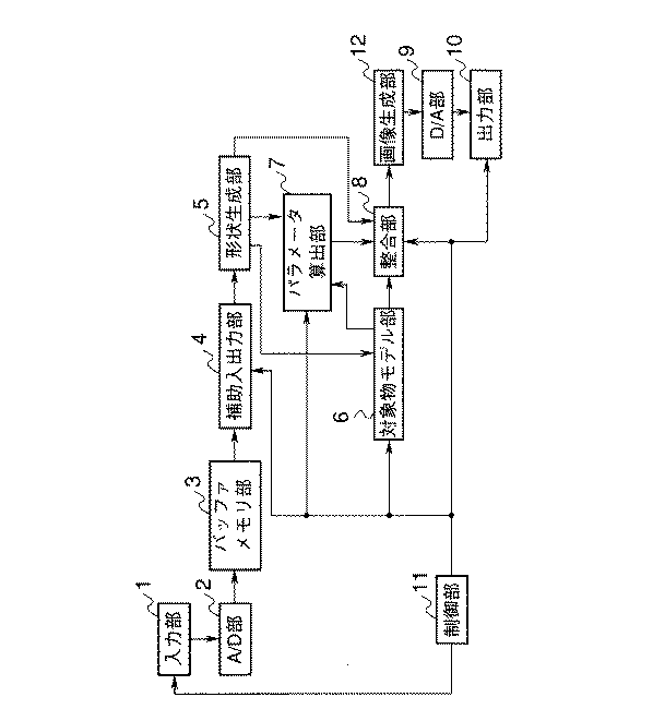
図1は、本発明による第1実施形態としての時系列画像解析装置の概略的な全体の構成例を示す図である。
【0009】
この時系列画像解析装置は、CCDカメラ等からなる画像の入力部1と、上記入力部1からの画像入力信号をデジタル化するA/D部2と、上記A/D部2からのデジタル画像信号をフレーム単位で一時的に記憶するバッファメモリ部3と、上記バッファメモリ部3からの画像データを保存する磁気ディスク等からなる補助入出力部4と、上記画像データ中で背景(静止画像領域)から所望の対象物(動画像領域)を抽出し、シルエット画像として生成する形状生成部5と、上記形状生成部5により生成されたシルエット画像を、予め解析の対象となる物体の各部位(パーツ)の形状に対応する単純な幾何学的な形状、例えば図2に示す楕円のような幾何学形状で各部位を表現するためのモデル形状や動作の情報などが格納されている対象物モデル部6と、上記形状生成部5と上記対象物モデル部6により対象物を構成する部位に分割し、各部位の位置や傾斜角のパラメータを概略的に算出するパラメータ算出部7と、上記対象物モデル部6が出力するパラメータ群全体を上記パラメータ算出部7により算出されたパラメータ群全体及び形状生成部5が生成したシルエット画像群に整合させる整合部8と、上記整合部8で算出されたパラメータ群を画像生成部12に出力する。上記画像生成部12にて画像化された解析結果の出力をアナログ化するD/A部9と、アナログ化された画像データを出力する出力部10と、これらの構成部の動作を制御する制御部11とで構成される。
【0010】
以上のように構成された時系列画像解析装置における画像解析について説明する。
まず、入力部1は撮影した映像を光電変換し、制御部11の制御に基づき、所定時間の映像信号としてA/D部2へ転送する。上記A/D部2は、上記映像信号をデジタル画像信号に変換し、バッファメモリ部3へ転送する。このバッファメモリ部3は、複数のフレームメモリで構成され、A/D部2からの上記デジタル画像信号を一時的に記憶し、フレーム単位の画像データに変換して順次、磁気ディスク装置などの補助入出力部4へ出力する。
【0011】
上記補助入出力部4は、制御部11の制御により上記画像データを形状生成部5へ出力する。形状生成部5では、上記画像データにおいて、解析処理の対象物が存在しない背景画像と、対象物の存在している原画像との差の絶対値を算出した後、2値化処理し、動画像領域(対象物のシルエット画像)のみを取り出す。ここで、上記背景画像は、予め撮影したものを用いてもよいし、原画像から背景画像を生成して用いてもよい。
上記形状生成部5で生成されたシルエット画像は、対象物モデル部6、パラメータ算出部7、整合部8にそれぞれ出力される。
【0012】
上記対象物モデル部6は、制御部11の制御により、シルエット画像と対象物の形状の情報を用いてモデルサイズの校正を行う。上記パラメータ算出部7では、制御部11の制御により、形状生成部5のシルエット画像と、対象物モデル部6の各出力から対象物の各部位の位置や傾斜角のパラメータを概略的に決定する。 具体的な一例としては、形状生成部5で生成されたシルエット画像よりスケルトンの抽出を行う。抽出されたスケルトンは、元のシルエットの幅の情報を含んでいる。また、スケルトンの抽出方法に関しては、例えば、総研出版刊「コンピュータ画像処理入門」(p77)などに記載されており、ここでの詳細な説明は省略する。
【0013】
次に上記対象物モデル部6の各部位のサイズに基づきスケルトンの分割を行う。分割されたスケルトンの中心点が各部位の位置に、傾きが傾斜角に相当する。また、中心点におけるスケルトンの幅情報を許容範囲εとする。
【0014】
そして、形状生成部5で生成されたシルエット画像、対象物モデル部6のモデル、パラメータ算出部7で算出された各部位のパラメータは、整合部8にそれぞれ出力される。上記整合部8では、形状生成部5、対象物モデル部6、パラメータ算出部7の各出力を用いて、時系列画像中の対象物と対象物モデル部6の動作に関する時刻の同期を行い、パラメータ算出部7により算出されたパラメータ群全体と対象物モデル部6のパラメータ群全体および形状生成部5のシルエット画像群との関係を照合し、誤差を最小化させる。
【0015】
上記整合部8の出力は、制御部11の制御により、画像生成部12に転送され、算出されたパラメータを例えば、楕円等で表すことにより画像化する。上記画像生成部12で生成された画像は、D/A部9に転送して、アナログ信号に変換される。さらに制御部11により上記アナログ信号をディスプレイ等の出力部10へ出力し、画像解析結果を表示する。
【0016】
次に図2は、対象物モデル部6に格納されているモデルを説明するための図である。
図2(a)は、例えば、人間の形状を対象物とし、この形状を胴体、頭、手足等の複数の部位に分解して、楕円で表現した場合のモデルを示す。但し上記楕円は単純な幾何学的形状の一例であり、数字は部位の番号であり、a,bは、各部位の長さを表す。このモデルでは、各部位のサイズ比、接続関係など対象物に関して、予め分かっている標準的な情報が格納してある。
【0017】
図2(b)は、各部位の接続関係と接続番号を示す。
対象物の各部位の大きさを対象物の身長に対する比率として定義し、対象物モデル部6に格納する。また、各部位の大きさの校正を行うために、モデルの対象物の高さ方向の大きさ(身長)mhもモデルの一部として格納しておく。なお、単純な幾何学的形状としては、楕円に限定されるものではなく、線分や円柱などで記述することも勿論可能である。
【0018】
また、対象となる動作の各部位の位置や傾斜角の理論的な数値データが時刻に対応して格納されている。対象物の対象となる動作の数値データの算出を行うために、マーカを用いて数値データを収集する。ここで、数値データとは、各部位の中心位置(x,y)、傾斜角θのことである。
【0019】
マーカを対象物の各部位の中心位置に装着し、対象となる動作の撮影を行う。撮影された画像からマーカを抽出し、抽出されたマーカの重心を各部位の中心点(x,y)とする。このマーカの傾斜角は、例えば抽出されたマーカの細線化を行い、この線の傾きを角度θとする。マーカの形状は、例えば長方形など傾斜角の算出が行うことが可能である形状であればよい。
【0020】
また、マーカは各部位の接続位置つまり、関節に装着してもよい。この場合の数値データの算出方は、マーカを抽出し、各マーカの位置の算出を行う。接続関係にある部位の2つのマーカの位置を用いて(1)式に示すように部位の長さ、傾斜角、中心点の算出を行う。
このマーカを各部位の接続位置に装着することにより、各部位の長さを正確に算出することができる。なお、マーカ形状は、円形のように動作の妨げにならず、各部位の長さ、傾斜角、中心点の算出が行うことが可能である形状であればよい。また、上記2つのマーカは、色マーカや電球のように公知であるマーカを用いて行うこともできる。
【0021】
図13は、マーカ装着と数値データ算出法の概念図であり、(a)は、マーカを各部位の中心位置に装着した例であり、(b)は、マーカを各部位の接続関係にある部位に装着した例である。
【0022】
【数1】
ここで、(xi ,yi ),(xj ,yj )は接続関係にある部位のマーカの位置であり、(x,y)は各部位の中心点、θは各部位のなす傾斜角、aは各部位の長さを表している。
【0024】
また、算出された数値データは、全て格納してもよいし、対象となる動作に周期性がある場合、動作の周期成分を抽出し、一周期分のみ格納してもよい。また、対象となる動作の理論的な数値データは時間に対応させて、図14に示すようなテーブルとして保存してもよいし、各数値データを各部位ごとに補間関数により数式化して係数のみを保存してもよい。また、図3に示すような存在可能領域として保存してもよい。
【0025】
次に図15は、対象物モデル部6に格納されている各数値データを各部位ごとに補間関数により数式化して格納する概念を示す。図15(a)に示すように、格納された時刻i−1,i,i+1の各数値データから微分値(差分値)を算出する。
【0026】
そして図15(b)に示すように、この微分値の変動が所定の閾値以上になる点を節点とする。抽出された節点間をスプライン関数などで補間を行い、算出された係数のみを格納しておく。スプライン関数に関しては例えば、「スプライン関数入門」(電機大出版局)などに記載されている。なお節点は、時刻i−1,i,i+1の各数値データの2次微分値の変曲点としてもよい。変曲点を節点とすることにより、数値データの変化が小さい運動についても節点を抽出することができる。
【0027】
なお、対象となる部位の動作に周期性がある場合、その動作の周期成分を抽出し、一周期分の各部位の論理的な(理論的な)数値データを格納してもよい。また、対象となる部位の動作の論理的な(理論的な)数値データは、時間に対応させたテーブルの形態で保存してもよい。また図3に示すような存在可能領域として保存してもよい。
【0028】
図3(b)に示すような歩行1周期における各部位の存在可能領域を理論的な数値データを基に以下のように算出する。
モデルの画像から対象物の領域(シルエット)を包含する矩形を公知である手法で、図3(a)のように抽出し、この矩形のx軸方向の中心線(中点)を求める。この中心線を一致させるように、つまりx座標を一致させるように各部位の理論的な数値データ(中心点)を重ね合わせる。
【0029】
これにより図3(b)の黒点で示す各部位の中心点の分布を求めることができる。この中心点の分布を包含する領域、つまり、各部位の中心点が存在可能な領域として存在可能領域を定める。この存在可能領域は、幾何学的な形状である楕円や半円のパラメータの組み合わせで記述する。
【0030】
具体的には、頭部と胴体部は、中心点の平均値を中心とする楕円で示し、手部・上腕部・前腕部は肩の位置を、大腿部・臑部・足部は腰の位置を中心とする円(扇形)の組み合わせで示している。肩・腰の位置(xshoulder,yshoulder),(xwaist ,ywaist )は(2)式で算出される。
【0031】
【数2】
ここで、(x2 ,y2 )は上記で算出した胴体部の中心点、a2 は胴体部の長さ、θ2 は胴体部の傾斜角を示す。
(3)式を用いて、手部・上腕部・前腕部・大腿部・臑部・足部の中心点を包含するような幾何学的な形状の算出を行う。
【0033】
【数3】
ただし、rは各部位の中心点を全て包含するような円の半径、phiは円周角を示す。図16は、半径rや円周角phiの算出方法の説明図である。これらは円の中心点((xshoulder,yshoulder)または(xwaist ,ywaist ))と各部位の全中心点との距離と角度を例えば(4)式のように算出する。
【0035】
【数4】
ここで、x03は、時刻0、部位番号3のx座標を示し、r0 ,phi0 は腰の位置から部位番号3である大腿部までの距離、角度を示す。この計算を解析を行う全ての時刻に対して行い、ri ,phii の最大・最小の値からrmax ,rmin ,phimax ,phimin を自動的に求めることができる。この操作を各部位に関して行う。
求められた図3(b)に示す存在可能領域は画像として格納するのではなく、半径rや円周角phiや中心点(x,y)や回転角θや長軸・短軸の長さa,bのパラメータをテーブルとして格納しておく。処理を行う際、このパラメータを用いて図3(b)に示す画像として回復する。
【0037】
図4は、前述した整合部8の具体的な構成を示すブロック図である。
この整合部8において、形状生成部5と対象物モデル部6の出力は、同期部21に転送される。同期部21では、形状生成部5のシルエット画像群と対象物モデル部6のモデルのパラメータ群から同期をとるために、同じ動作となる時刻を複数個算出する。対象物モデル部6と同期部21の各出力は、周期校正部22に転送される。本実施形態では、解折対象の動作に周期性があるものを前提としている。そこで、周期校正部22では、同期部21で算出された複数の同期時刻とから算出される1周期にかかる時間と、対象物モデル部6の出力であるモデルパラメータに予め含まれているモデルの1周期にかかる時刻とに基づいて、モデルデータの周期の校正を行う。形状生成部5と対象物モデル部6とパラメータ算出部7と同期部21と周期校正部22はパラメータ修正部23に出力される。
【0038】
このパラメータ修正部23では、一画像内でモデルとの対比による時系列画像のパラメータの修正を行う。形状生成部5と対象物モデル部6とパラメータ算出部7とパラメータ修正部23の出力は、最適化処理部24に転送する。最適化処理部24では、パラメータ算出部7により算出されたパラメータ群全体を周期校正された対象物モデル部6のパラメータ群全体および形状生成部5のシルエット画像群に整合される。
【0039】
図5は、同期部21の処理における概念図である。同期部21では、時刻timeにおけるモデルの位置や傾斜角のパラメータを用いて単純な幾何学的形状の一例として楕円を生成し、時系列画像中の対象物のシルエット画像群とのマッチングを行う。マッチング誤差が最小となるシルエット画像の時刻が、モデルにおける時刻timeに相当することになる。
【0040】
上記同期部21について、対象物が人間である場合の具体的な例を、図17に示すフローチャートを参照して説明する。
まず、モデルから基準動作であるclose状態(手足が閉じている状態)の時刻crossの算出を行う(ステップS1)。図18はclose状態の算出方法の概念図である。基準動作close状態の時刻の算出方法は、対象物モデル部6に格納されているモデルのパラメータをスプライン関数から算出し、全ての時刻に関して頭部(部位の番号0)と他の部位群とのx座標の差の総和を算出する。この総和が一番小さくなる時刻がcrossとなる。図5は同期時刻timeの算出方法の概念図である。
【0041】
次に、時刻crossのモデルのパラメータを用いて時刻crossのモデルの楕円画像を生成する(ステップS2)。この時刻crossのモデルのシルエット画像と時刻timeの時系列画像のシルエット画像を包含する外接四辺形を公知である手法で抽出し、この外接四辺形のx軸方向の中心線を一致させる。時系列画像のシルエット画像とモデルの楕円画像との面積差を算出する。
全ての時刻の時系列画像のシルエット画像との面積差を算出し、面積差が最小である時刻periodが時刻crossと同動作を行う時刻である(ステップS3)。
【0042】
以上のように、モデルのclose状態の楕円画像と時系列画像中の対象物のシルエット画像群とのマッチングを行うことで、モデルと時系列画像との同期をとることができる。
また、以下のような方法でも同期時刻を算出することも可能である。対象物モデル部6に格納されているモデルのシルエット画像群と時系列画像のシルエット画像群の面積の最小(又は最大)となる時刻を複数個算出する。算出された時刻がモデルと時系列画像の同期の時刻となる。例えば、人間の歩行動作を解析対象とした場合、シルエット画像の面積が最小となるときは、ほぼ直立した状態を示している。ここで、モデルと時系列画像のシルエットの面積最小時刻を算出するということは、直立状態の時刻の同期をとっていることになる。このようにすることで、楕円画像を生成する必要がなくなるので、処理時間を短縮することができる。
【0043】
図6と図20は、周期校正部22の処理における概念を示す。周期校正部22は、対象となる動作に周期性がある場合のみ行われる。同期部21により算出された複数の同期の時刻により、一周期にかかる時間Tの算出を行う。対象物モデル部6に格納されているモデルの一周期にかかる時間MTと時系列画像の一周期にかかる時間Tとの比ra=MT/Tを求め、この比raを用いてモデルの周期の校正を行う。
【0044】
図19に示すフローチャートを参照して、周期校正部22について説明する。対象物モデル部6に格納してあるモデルの一周期分の動作の時刻MT とし、同期部21により算出された複数の同期の時刻により、一周期にかかる時間Tの算出を行う(ステップS11)。モデルの一周期にかかる時間MT と時系列画像の一周期にかかる時間Tとの比ra=MT/Tを求め(ステップS12)、この比raを用いてパラメータ修正部23でモデルの周期の校正を行う。この処理は、一周期単位で行われる。このため対象物の動作が周期が増すごとに加速するような状況にも対応できる。これは動作の数値データをスプライン関数の係数として保存しているため、任意の時刻の数値データが算出できるためである。
【0045】
図7は、パラメータ修正部23の処理における概念図である。パラメータ修正部23では、時系列画像の時刻timeの各部位のパラメータと時刻timeに対応するモデルの各部位のパラメータの差の算出を行う。パラメータ算出部7で算出された許容範囲εを閾値とする。各パラメータ間の差が所定の閾値以上であるとき、時系列画像のパラメータをモデルのパラメータに置換し、例えば単純な幾何学的形状の一例として楕円を生成し、シルエット画像との誤差の算出を行う。算出された誤差が置換前より増加した場合、パラメータの置換は破棄される。上記過程を各パラメータに対して行い、画像内でのパラメータの修正を行う。
【0046】
図21に示すフローチャートを参照して、パラメータ修正部23について説明する。
モデルの対象物と時系列画像の対象物の大きさの比率の算出を行う(ステップS21)。対象物モデル部6に格納してあるモデルの対象物の高さ方向の大きさをmhとし、時系列画像の対象物(シルエット画像)を包含する外接四辺形を算出し、高さ方向の大きさhを算出する。これを用いてモデルと時系列画像の対象物の大きさの比率scale=mh/hを算出する。対象物の各部位の大きさを比率scale倍して大きさの修正を行った後、以下の処理を行う。
【0047】
周期校正部22で算出した比率raを用いて時系列画像に対応するモデルの時刻の算出を行う(ステップS22)。モデルの時刻を比率ra倍し、時系列画像の時刻がra倍されたモデルの一周期分の時刻を越えていたら、越えた分だけモデルの始め時刻に対応するように合わせる。
【0048】
時刻timeの初期設定を行う(ステップS23)。時刻の同期がとれたら時刻timeの時系列画像のパラメータから楕円画像を生成する(ステップS24)。時刻timeの時系列画像のシルエット画像と楕円画像との面積差を算出し、diff1に格納する(ステップS25)。
【0049】
同期処理を行った時刻timeのモデルのパラメータをスプライン関数から算出し、時刻timeのモデルと時系列画像のパラメータの差の絶対値の算出を各部位毎に行う(ステップS26)。差の絶対値をパラメータ算出部7で算出された許容範囲εと比較し(ステップS27)、小さければ(NO)ステップS28に移行し、時刻timeのインクリメントを行い、ステップS24に戻る。
【0050】
しかし、ステップS27で大きければ(YES)、モデルと時系列画像のパラメータの入れ替えを各部位毎に行う(ステップS29)。時系列画像の対象物とモデルの対象物の位置が異なるため、シルエット画像を利用して、位置合わせを行い、パラメータの入れ替えを直接行うようにする。時刻timeの時系列画像のシルエット画像とそれに対応するモデルのシルエット画像を包含する外接四辺形を抽出し、外接四辺形のx軸方向の中心線を一致させる。つまり、外接四辺形の中心のx座標を一致させるためのモデルの移動量を算出し、この移動量をもとにモデルのパラメータの修正を行い、入れ替えを行う。
【0051】
入れ替えたパラメータから楕円画像の生成を行い(ステップS30)、ステップS25と同様にステップS30で生成した楕円画像とシルエット画像の面積差を算出し、diff2に格納する(ステップS31)。パラメータ入れ替え前の面積差diff1と入れ替え後の面積差diff2を比較し(ステップS32)。diff2がdiff1より小さい場合(NO)、ステップS28に戻り、時刻timeのインクリメントを行い、ステップS24に戻る。一方、大きい場合(YES)、パラメータの入れ替えを破棄する(ステップS33)。ステップS24からステップS33は、全ての部位に対してまとめて処理を行う。時刻timeと時系列画像の終了時刻を比較し、時刻timeが終了時刻より小さい場合(NO)ステップS28に戻り、時刻timeのインクリメントを行い、ステップS24に戻る。大きい場合(YES)処理を終了する。
【0052】
図8は、最適化処理部24の処理における概念図である。上記パラメータ算出部7で算出された時系列画像のパラメータ群、対象物モデル部6のモデルのパラメータ群と形状生成部5で生成されたシルエット画像群の三者を整合する。このための手法の一例として評価関数を設定し、最小化する。例えば人間を対象とした解析の場合、(5)式のように評価関数ET定義し、評価関数ETをアニーリングや最急降下法などを用いて最小化することにより、時系列画像のパラメータ群の最適なパラメータの算出を行う。
【0053】
【数5】
ここで、Tは周期、i=T〜T+1は時刻、j=1〜14は部位、l=1〜13は図2(b)に示すような各部位の接続番号、Pmはモデルのパラメータ群、Pは時系列画像中の対象物の各部位のパラメータ群である。第1項は対象物のパラメータをモデルのパラメータと整合させる。Silは時系列画像中の対象物のシルエット画像、Parは時系列画像のパラメータにより生成した楕円画像であり、第2項は時系列画像のパラメータをシルエット画像に整合させる。
【0055】
Lm及びLは、図2(b)に示される13組の接続関係にある部位の中心点間の距離である。つまり頭部と胴体部などの結合関係にある部位の中心位置間の距離である。Lmはモデルに関する各部位の中心点間の距離、Lは時系列画像中に関する各部位の中心点間の距離を表す。第三項は、時系列画像中の対象物の各部位間のパラメータの結合関係をモデルの結合関係に整合させる。kは、それぞれの項のウエイトである。
【0056】
なお、(6)式のような評価関数ETをアニーリングや最急降下法などを用いて時系列画像のパラメータ群の最適なパラメータの算出を行うことも可能である。
【0057】
【数6】
ここで、Tは周期、i=T〜T+1は時刻、j=1〜14は部位、l=1〜13は図2(b)に示すような各部位の接続番号。Pmはモデルのパラメータ群、Pは時系列画像中の対象物の各部位のパラメータ群である。第一項は対象物のパラメータをモデルのパラメータと整合させる。Silは時系列画像中の対象物のシルエット画像、Parはモデルのパラメータにより生成した楕円画像であり、第二項はモデルのパラメータをシルエット画像に整合させる。Lm及びLは、図2(b)に示される13組の結合関係にある中心点間の距離である。つまり、頭部と胴体部などの結合関係にある部位の中心位置間の距離である。Lmはモデルに関する各部位の中心点間の距離、Lは時系列画像中に関する各部位の中心点間の距離を表す。第三項は、時系列画像中の対象物の各部位間のパラメータの結合関係をモデルの結合関係に整合させる。Pcは時刻i−2,i−1,i,i+1,i+2の時系列画像のパラメータに、重みをそれぞれ1:2:3:2:1だけ与え、平均値を算出した値であり、第四項は、時系列画像のパラメータを前後の時刻から推測されるパラメータ値に整合させる。kは、各項に対するウエイトである。
【0059】
上記3者の整合をとり、時系列画像のパラメータ群の最適なパラメータの算出をアニーリングを利用して行う方法を以下に示す。図22に示すフローチャートを参照して、最適化処理部24を説明する。
【0060】
まず、温度Tempint と反復回数nの初期設定を行う(ステップS41)。iterationとTempの初期設定を行う(ステップS42)。初期エネルギーinit engの算出を行う(ステップS43)。
初期エネルギーは、(5)式や(6)式の評価関数を計算した結果を表す。乱数ranを発生させ、微小変化を与える値gとパラメータの種類xyrと時刻timeと部位番号pを決定する(ステップS44)。例えば、0〜1までの乱数を発生せた場合の各パラメータは、
time=ran×画像の枚数
xyr=ran×3 (xyr=1の時x,xyr=2の時y,
xyr=3の時rad)
p=ran×14
g=部位番号pの部位の長さ×(ran×2.1−1.0)
として与えられる。
【0061】
時刻timeの時系列画像のパラメータxyr[time][p]に微小変化gを与える(ステップS45)。微小変化を与えたパラメータを用いてエネルギーengの算出を行う(ステップS46)。初期エネルギーinit engとエネルギーengを比較し(ステップS47)、init engがengより小さいならば(NO)、ステップS48にに移行し、乱数ranとexp[(eng−init eng)/Temp]を比較し、条件を満たさないならば(NO)、ステップS44に戻り、新たな乱数ranを発生させる。
【0062】
またステップS48又はステップS47の条件を満たすならば(YES)、この微小変化を受け入れ、パラメータ値の更新を行い、エネルギーの値の入れ替えを行う(init eng=eng)(ステップS49)。
反復回数iterationがs初期値nより小さいか否か判断し(ステップS50)、条件を満たす場合(YES)、温度を下げ、反復回数iterationを更新した後(ステップS51)、ステップS44に戻り、新たな乱数ranを発生させる。しかし条件を満たさない場合には(NO)、最適化処理を終了する。
【0063】
また最適化処理を行うにあたって、条件によっては本来接続している部位、例えば手部と前腕部とが離れてしまうことがある。これを防ぐために、各部位のパラメータに与える微小変化の範囲を限定し、各部位の分離を防止する方法を説明する。各部位の分離を防止するために、従来不変としてきた長軸,短軸の長さを適応的に調節するモデルを付加する。具体的には、最適化処理で微小変化を与える時に分離を防止するような制限を設ける。
【0064】
各部位の中心座標に微小変化を与える場合を考える。
この段階では所定の長さの長軸で結合していることを仮定する。微小変化を与える注目部位とそれに連結している部位の長軸の長さを所定長だけ延長する。延長した長軸を半径とする円を考える。この円が分離しないよう、つまり常に接する、または交差するように注目している部位の円を移動する。
【0065】
このときの中心座標が描く軌跡が、結合を維持したままで微小変化を与えられる領域となる。図23は、対象物が人間である場合の各部位の分離防止に関する概念図である。図23をもとに人間の場合について具体的に説明する。例えば、手部と上腕部に結合している前腕部の中心座標に微小変化を与える場合を考える。この段階では所定の長さの長軸で結合していることを仮定する。手部,上腕部,前腕部の長軸の長さを所定長(例えば10%)延長し、この3つの円が分離しないよう、前腕部の(10%膨張した)円を移動する。
【0066】
このときの中心座標が描く軌跡が、結合を維持したままで微小変化を与えられる領域となる。ただし、端点の注目部位とそれと連結する部位が分離しないような円の移動は、モデルに基づき各関節間の移動可能範囲角度を越えないように行う。なお、長軸と同じ比率だけ短軸を調整することで、プロポーションを一定に保つことができる。
以上のように行うことで、微小変化の付与を限定することになるので、最適化処理を高速化でき、各部位の分離を防止することができる。
【0067】
また、本発明は関節がパーツでつながれた動体、例えば多関節ロボットや動物などの動きの解析も同様な方法で行うことが可能である。例えば、多関節ロボットの動きの解析を行う場合、以下のように行う。ロボットに関する形状の知識 (大きさ・接続関係)と関数化された各部位の動作の知識と各部位の存在可能領域をロボットの動きの知識として格納する。
【0068】
背景画像と入力画像との差をとり、シルエット画像を抽出する。シルエット画像と存在可能領域とのAND処理を行うことにより、各部位の概略的なパラメータの算出を行う。このパラメータをモデルを用いて修正し、最適化処理を行う。この手法により、ロボットの動きを解析し、これをもとに最適化することができる。
【0069】
また、形状生成部5のシルエット画像を用いない最適化も考えられる。
一例として、以下のような判定基準が挙げられる。モデルのパラメータ群と時系列画像中の対象物の各部位のパラメータ群の差がある閾値以下であり、且つ、時間的に前後の画像の同部位のパラメータと時系列画像中の対象物の各部位のパラメータ群の差がある閾値以下ならば、置換しないものとする。
【0070】
そして整合部8で算出されたパラメータを制御部11からの制御に基づき、画像生成部12に出力する。上記画像生成部12では、整合部8で算出されたパラメータに基づいて、例えば、楕円を生成し、各部位のパラメータの画像化を行う。ただし、楕円ではなく、線分や円柱などで画像化を行ってもよい。上記画像生成部12にて画像化された解析結果の出力をD/A部9に転送し、アナログ信号に変換する。さらに制御部11からの信号に基づき、上記アナログ信号をディスプレイなどの出力部10へ出力し、画像解析結果をディスプレイなどで表示する。すなわち、図9(a)に示すような時系列画像に関して、図9(b)に示す解析結果が得られる。
【0071】
以上のような時系列画像解析装置は、対象物の動作のパラメータを数式化することで情報量を削減でき、モデルの各部位のサイズや位置を校正することで多くの被写体に適用でき、撮影距離の差によるサイズの違いも補正できる。また、遮蔽や影の影響により対象物の形状や動作が正確にとらえられなかった場合に、対象物の形状や動作による形状変化の知識を用いて補正を行い、対象物の動作を高精度に解析することができる。また、周期性を利用することにより、モデルの情報量を削減することができ、周期を校正することで同じ動作で速度が異なる場合にも対応することができる。
【0072】
以上の説明では、同期部21において同期する時刻を決定して動きのマッチングを行うものとしたが、この処理を省略し、時系列画像群とモデルパラメータ群との全ての組み合わせについて探索を行うようにしてもよい。
また、周期校正部22において周期性のある動作について周期の校正を行うものとしたが、この処理は省略してもよい。また周期校正部22は、同期部21が省略されている場合に行われない。
【0073】
また、パラメータ修正部23においてパラメータの修正を行うものとしたがこの処理は省略可能である。また本実施形態では、各部位を表現する単純な幾何学的形状として楕円を用いたが、線分や円柱などで記述することもよい。
【0074】
次に第2実施形態の時系列画像解析装置について説明する。
この第2実施形態の構成は、基本的には第1実施形態と同等であり、ここでは異なる部分のみ説明を行う。
図10は、第2実施形態におけるパラメータ算出部7の具体的な構成例を示す。ここで、第1実施形態と同等の構成部には第1実施形態の構成部と同じ参照符号を付し、その説明を省略する。
【0075】
このパラメータ算出部7は、形状生成部5と対象物モデル部6からの出力が候補領域算出部31に転送される。この候補領域算出部31の出力は、整合部8に転送される。最適化処理を高速に行うため、対象物の各部位の位置や傾斜角のパラメータを概略的に算出を行うものである。
時系列画像中の対象物の各部位の候補領域を算出し、算出された候補領域と対象物の形状から候補領域の結合関係を求め、結合関係にある領域群の各位置や傾斜角のパラメータおよび各パラメータが存在する可能な範囲の算出を行う。以降、各パラメータが存在する可能な範囲を許容範囲という。
【0076】
図11は、時系列画像中の対象物の各部位の候補領域の算出における概念を示す。パラメータの算出方法について、図24のフローチャートを参照して、候補領域算出部31を説明する。
対象物モデル部6に格納されている各部位の存在可能領域のパラメータ群を画像化する(ステップS51)。具体的には、対象物モデル部6に格納されている幾何学的な形状である円や楕円などのパラメータ(中心点・半径・回転角など)を用いて画像の生成を行う。例えば、(3)式を満たす画素(x,y)には1を、満たさない場合には、“0”を格納し、2値画像の生成を行う。
【0077】
次に図3のように画像化した存在可能領域とシルエット画像を用いて各部位の候補領域の算出を行う(ステップS52)。図11(b)に示すシルエット画像に外接する矩形を求め、この矩形の中心線を求めておく。また、ステップS52で画像化された存在可能領域に外接する矩形から中心線の位置を算出し、両者の中心線を一致させた形でAND出力を求める。
【0078】
この結果が、図11(c)に示すような各部位が存在する候補領域になる。抽出された各部位の候補領域から端点領域の選択を行う(ステップS53)。端点領域とは、一方向のみが他の領域と結合している領域(手や足)のことである。まず、端点領域の重心点(x,y)の算出を行う(ステップS54)。重心点の算出方法は、例えば端点領域のxおよびy座標を加算し、それぞれの加算された値を端点領域の画素数で割った値などがある。
【0079】
図12は、候補領域と対象物の形状から候補領域の結合関係を求め、結合関係にある領域群の各位置や傾斜角および許容範囲の算出する処理の概念を示す。時系列画像の対象物の各部位の位置(中心点)は以下のように算出される。
まず、端点領域と結合関係にある結合領域の算出を行う(ステップS55)。具体的には、端点領域の部位の大きさlと、端点領域と接続する他の領域の部位の大きさl′と対象物モデル部6の対象物の形状により結合関係を求める。対象物が人間の場合、端点領域である手と結合関係にある部位は前腕であるので、l,l′には、それぞれの部位の長軸の長さが格納される。
【0080】
そして各領域の結合関係について、次のように算出される。端点領域の重心点を中心とする半径R(=(l+l′)/2)の円を描き、その円上に存在する領域を端点領域と結合する領域つまり結合領域とする。円と結合領域が重複する部分の重心を、結合する領域の中心点(x,y)とする(ステップS56)。
【0081】
図12(b)は、端点領域の重心を中心点とする半径(l+l′)/2の円と重複する領域であり、図12(d)の結合領域の太線が円と結合領域が重複する部分となる。また、円弧が結合領域と重複した円弧の長さの1/2を許容範囲εとする(ステップS57)。つまり、図12(d)の結合領域の太線(重複した領域)のどこでも中心点となりえる可能性を持っているため、この重なり部分の1/2をεとし、中心点の座標を(x±ε,y±ε)とする。
【0082】
図12(d)は、許容範囲εの算出方法の概略図を表す。全ての部位の結合領域を検出したか否か判断し(ステップS58)、全ての部位に関して検出していない場合(NO)、結合領域を新たな端点領域とし(ステップS59)、ステップS55にフィードバックする。
全ての部位に関して検出を行った場合(YES)、各部位の重心点に対応する傾斜角の算出を行う(ステップS60)。具体的には、0°〜180°まで5°間隔で上記で算出した点(x,y)を中心点とする楕円を生成し、シルエット画像とのマッチング誤差が最小となった角度傾斜角とする。
【0083】
図12(e)には、傾斜角の算出方法の概略を示す。ただし、結合領域を算出する際、複数の結合領域が検出された場合には、対象物の形状や結合関係にある部位間の傾斜角などの情報を用いて、矛盾が生じる場合にはその結合関係は破棄し、結合関係の絞り込みを行う。
なお、時系列画像中の対象物の移動方向と対象物モデル部6に格納されているモデルの移動方向が逆の場合にも以下のようにすることにより適応することができる。
【0084】
まず、時系列画像から対象物の移動方向の検出を行う。移動方向の検出方法は、例えば、シルエット画像の重心を算出し、重心のx座標の変化で求めることができる。対象物の移動方向が、対象物モデル部6に格納されている動作の移動方向と一致しているか判断を行う。同一方向であれば、モデルのパラメータをそのまま使用し、逆方向の場合には以下の処理を行い、モデルの動作を反転させる。対象物が人間である場合のモデルの動作を反転する手法に関する具体的な例を以下に示す。図49は、モデルの反転に関する概念図である。
【0085】
補間関数から各時刻の胴体部の位置(x2 ,y2 )座標の算出を行う。胴体部(i=2)以外の部位iに関して、胴体部と各パラメータとの差の算出を、図49のΔx5 =(x2 −x5 )やΔy5 =(y2 −y5 )のように行う。胴体部のパラメータ(x2 ,y2 ,θ2 )に先で算出した差を加算し、部位に対応する逆の部位(例えば、右手ならば左手)に加算結果を格納する。つまり、x8 =Δx5 +x2 ,y8 =Δy5 +y2 のように行う。
【0086】
この様に行うことで、1つのモデルで逆向きの動きを行っている対象物の動作の解析も行うことができる。なお、上記の説明では、各部位を表現する単純な幾何学的形状として楕円を用いたが、これは楕円だけでなく線分や円柱などで記述することも可能である。
図12(e)においては、各部位を表現する単純な幾何学的形状として楕円を用いたが、これは楕円だけでなく線分や円柱などで記述することも可能である。本実施形態では、時系列画像中の対象物の各部位のパラメータを概略的に算出することで最適化処理の負担を軽減し、処理時間を短縮することができる。
【0087】
次に第3実施形態としての時系列画像解析装置について説明する。
図25には、第3実施形態として、時系列画像解析装置の全体構成の一例を示す。本実施形態の構成は、基本的には第1実施形態と同等であり、同じ構成部材には同一の参照符号を付し、異なる部分のみ説明する。
【0088】
この時系列画像解析装置において、入力部1からの入力信号は、A/D部2、バッファメモリ部3を経由して補助入出力部4に保存される。補助入出力部4の信号は、形状生成部5へ出力される。形状生成部5の出力は、対象物モデル部6、整合部41に転送される。対象物モデル部6は、整合部41に接続されている。整合部41で算出されたパラメータを制御部11からの制御に基づき、画像生成部12に出力する。上記画像生成部12にて画像化された解析結果の出力をD/A部9を経由して出力部10へ出力される。また、制御部11の制御信号により、入力部1、補助入出力部4、対象物モデル部6、整合部41、出力部10がそれぞれ制御される。
【0089】
このような時系列画像解析装置は、高速な解析処理に好適し、対象物の各部位の位置や傾斜角の概略的なパラメータの算出を行なわず、モデルのパラメータを対象物の各部位の初期パラメータ値として扱うものである。
【0090】
まず、CCDカメラ等の入力部1は、制御部11からの制御信号に基づき所定時間の映像信号をA/D部2へ転送する。A/D部2は、入力部1からの上記映像信号をデジタル信号へ変換してバッファメモリ部3へ転送する。このバッファメモリ部3は、複数のフレームメモリで構成されており、A/D部2からの上記デジタル信号を記憶し、これを順次補助入出力部4へ出力する。
【0091】
上記補助入出力部4は、制御部11の制御信号により、上記デジタル信号を形状生成部5へ出力する。形状生成部5では、対象物の存在していない背景画像と対象物の存在している原画像との差の絶対値を算出した後、その絶対値を2値化処理し、動領域のみが取り出される。この動領域が対象物のシルエット画像となる。ここで、背景画像は、予め撮影されているものを用いてもよいし、原画像から生成された背景画像を用いてもよい。
【0092】
上記形状生成部5で生成されたシルエット画像は、対象物モデル部6、整合部41に転送される。対象物モデル部6は、対象物の形状や動作の情報などが格納されている。また、制御部11の制御信号により、前の実施形態で説明したと同様にサイズの校正を行う。形状生成部5で生成されたシルエット画像、対象物モデル部6のモデルは、整合部41に出力される。整合部41では、形状生成部5、対象物モデル部6の出力により、時系列画像中の対象物と対象物モデル部6の動作に関する時刻の同期を行い、対象物モデル部6のパラメータ群全体を形状生成部5のシルエット画像群に整合させる。
【0093】
そして整合部41で算出されたパラメータを制御部11からの制御信号により、画像生成部12に出力する。上記画像生成部12にて画像化された解析結果の出力をD/A部9に転送し、アナログ信号に変換する。さらに制御部11からの制御信号に基づき、上記アナログ信号をディスプレイなどの出力部10へ出力し、画像解析結果を表示する。
【0094】
次に図26は、整合部41の処理におけるブロック構成を示す。
前段の形状生成部5と対象物モデル部6の出力は、整合部41の同期部21に転送される。この同期部21では、時系列画像中の対象物と対象物モデル部6における動作に関する時刻の同期をとる。
【0095】
そして対象物モデル部6と同期部21の出力は、周期校正部22に転送される。周期校正部22では、制御部11からの制御信号により、対象となる動作に周期性がある場合には、同期部21で算出された複数の同期時刻とモデルに基づいて一周期に要する時間を算出し、各部位の位置や傾斜角のモデルのパラメータの校正を行う。そして形状生成部5と対象物モデル部6の出力は、最適化処理部51に転送する。最適化処理部51では、対象物モデル部6のパラメータ群全体を形状生成部5のシルエット画像群に整合させる。
【0096】
上記最適化処理部51では、対象物モでル部6のモデルのパラメータ群と形状生成部5で生成されたシルエット画像群の2者を整合する。このための手法の一例として評価関数を設定し、最小化する。例えば、人間を対象物とした解析の場合、(7)式のように評価関数ET定義し、評価関数ETを上記実施形態同様にアニーリングや最急降下法などを用いて最小化することにより、時系列画像のパラメータ群の最適なパラメータの算出を行う。
【0097】
【数7】
ここで、Tは周期、i=T〜T+1は時刻である。Silは時系列画像中の対象物のシルエット画像、Parはモデルのパラメータにより生成した楕円画像であり、第一項はモデルのパラメータをシルエット画像に整合させる作用をもつ。Pcは時刻i−2,i−1,i,i+1,i+2の時系列画像のパラメータに、重みをそれぞれ1:2:3:2:1だけ与え、平均値を算出した値である。第二項は、時系列画像のパラメータを前後の時刻から推測されるパラメータ値に整合させる作用をもつ。kは、各項に対するウエイトである。
【0099】
また前述した説明では、各部位を表現する単純な幾何学的形状として楕円を用いたが、これは線分や円柱などで記述することも可能である。
上記実施形態では、構成が簡単になり、時系列画像の初期パラメータの算出を行わないので、第1実施形態に比べて高速に処理を行うことができる。
【0100】
次に第4実施形態としての時系列画像解析装置について説明する。
本実施形態の全体的な構成は、第3実施形態と同等であり、異なる構成となる図27に示す整合部41のみ説明する。
この整合部41においては、形状生成部5と対象物モデル部6の出力は、最適化処理部61に転送する。最適化処理部61では、ニューラルネットワークを利用することにより、時系列画像のシルエット画像に最適な時系列画像の各部位のパラメータ群(位置)の算出を行う。対象物モデル部6と最適化処理部61の出力は傾斜角算出部62に転送され、時系列画像のシルエット画像に最適な時系列画像の各部位の回転角の算出を行う。傾斜角算出部62の出力は、画像生成部12に出力される。
【0101】
図27に示すように、上記形状生成部5の時系列画像のシルエット画像と対象物モデル部6のモデルのパラメータ群とシルエット画像群の出力は、最適化処理部61に転送する。最適化処理部61では、階層型ニューラルネットワークを用いて、時系列画像のシルエット画像に最適な時系列画像の各部位の位置のパラメータ群の算出を行う。最適化処理部61で算出された各部位のパラメータ群(位置)は、傾斜角算出部62に転送され、時系列画像のシルエット画像に最適な時系列画像の各部位の回転角の算出を行う。傾斜角算出部62で算出されたパラメータ群は、画像生成部12に出力される。
【0102】
図28(a)は、3層の階層型ニューラルネットワークの学習法に関する概念図である。対象物モデル部6に格納されているモデルのシルエット画像を、入力層に入力する。ネットワークを介した結果がモデルの各部位の位置のパラメータとなるように学習させ、各ユニットの重みを決定する。学習は、動作1周期分の画像に対して行われ、重みの更新を行う。なお学習方法は、例えば公知である誤差逆伝搬法を用いて行うことができる。この重みを利用し、撮影された画像の各部位の位置の算出を行う。形状生成部5の時系列画像のシルエット画像を入力層に入力し、ネットワークを介することで、シルエット画像に最適な各部位の位置の算出を行うことができる。図28(b)は、撮影された画像に対するパラメータ算出に関する概念図である。
【0103】
傾斜角算出部62では、最適化処理部61で算出された各部位のパラメータ群(位置)と対象物モデル部6に格納されている各部位の大きさ(楕円の短軸、長軸の長さ)と形状生成部5の時系列画像のシルエット群を用いて、時系列画像群の各部位の傾斜角の算出を行う。最適化処理部61で算出された各部位の位置(x,y)を中心点、対象物モデル部6の各部位の大きさ(楕円の短軸b/2、長軸の長さa/2)を用いて楕円の生成を行う。傾斜角に関しては、0°〜180°まで5°間隔で上記のパラメータを用いて楕円を生成し、シルエット画像とマッチング誤差が最小となった角度を傾斜角とする。また、傾斜角の算出は、前述した図12(e)にその概念を示している。そして、算出された各部位のパラメータ群から楕円画像を生成し、画像生成部9に転送する。
この第4実施形態では、ニューラルネットワークを用いることにより、最適化処理部24の構成が簡単になり、最適化パラメータの調整を意識的に行われなくても学習により、これを獲得することができる。
【0104】
次に第5実施形態としての時系列画像解析装置について説明する。
図29には、時系列画像解析装置の全体構成の一例を示す。本実施形態の全体的な構成は、第3実施形態と同等であり、同じ構成部位には同一の参照符号を付し、説明する。
【0105】
この時系列画像解析装置においては、入力部1からの入力信号は、A/D部2、バッファメモリ部3を経由して補助入出力部4に保存される。補助入出力部4の信号は、形状生成部5へ出力される。形状生成部5の出力は、対象物モデル部71、パラメータ算出部7、整合部72に転送される。上記対象物モデル部71は、パラメータ算出部7、整合部72に接続されている。
【0106】
そしてパラメータ算出部7の出力は、整合部72に接続されている。整合部72の出力は、対象物モデル部71と画像生成部12に出力される。画像生成部12の出力を、D/A部9を経由して、出力部10へ出力される。また制御部11の制御信号により、入力部1、補助入出力部4、対象物モデル部71、パラメータ算出部7、整合部72、出力部10がそれぞれ制御される。この時系列画像解析装置は、モデルを処理の進行に伴い適応的に学習させるものである。
【0107】
この時系列画像解析装置において、CCDカメラ等の入力部1は、制御部11からの制御に基づき所定時間の映像信号をA/D部2へ転送する。A/D部2は入力部1からの上記映像信号を、デジタル信号へ変換してバッファメモリ部3へ転送する。
そしてバッファメモリ部3は、複数のフレームメモリで構成され、A/D部2からの上記デジタル信号を記憶し、これを順次、磁気ディスク装置などの補助入出力部4へ出力する。補助入出力部4は、制御部11からの制御信号により上記デジタル信号を形状生成部5へ出力する。形状生成部5では、対象物のシルエット領域の抽出を行う。
【0108】
次に形状生成部5で生成されたシルエット画像は、対象物モデル部71、パラメータ算出部7、整合部72に転送される。対象物モデル部71は、対象物の形状や動作の情報などが格納されている。また動作に関する情報は、整合部72の出力に基づき更新される。パラメータ算出部7では、制御部11の制御に基づいて形状生成部5のシルエット画像と対象物モデル部71の出力から、対象物の各部位の位置や傾斜角のパラメータを概略的に決定する。
【0109】
そして、形状生成部5で生成されたシルエット画像、対象物モデル部71のモデル、パラメータ算出部7で算出された各部位のパラメータは、整合部72に出力される。整合部72では、形状生成部5、対象物モデル部71、パラメータ算出部7の出力により、時系列画像中の対象物と対象物モデル部71のモデルの時刻の同期を行い、対象物モデル部71のパラメータ群全体をパラメータ算出部7により算出されたパラメータ群全体、及び形状生成部5のシルエット画像群に整合させる。整合部72の出力を制御部11からの制御に基づき、対象物モデル部71と画像生成部12へ転送する。
【0110】
上記画像生成部12の出力は、D/A部9に転送し、アナログ信号に変換する。さらに制御部11からの信号に基づき上記アナログ信号をディスプレイなどの出力部10へ出力し、画像解析結果を表示する。
【0111】
以下に、対象物モデル部71および整合部72の説明を行う。
図30は、モデルパラメータの更新に関する概念を示し、図34は、対象物モデル部71の構成を示す。
まず制御部11からの制御により、形状知識部81と動作知識部82の出力をパラメータ算出部7と整合部72に転送する。パラメータ算出部7にて算出された概略的なパラメータと形状知識部81と動作知識部82の出力を整合部72に出力する。そして制御部11からの制御信号に基づき整合部72の出力は、動作知識部82にフィードバックされる。
【0112】
上記対象物モデル部71において、時系列画像の最初の一周期では、第1実施形態と同様に外部から与えられた形状知識部81と動作知識部82の初期モデルをパラメータ算出部7、整合部72に出力する。
【0113】
そして2周期目以降は、整合部72で算出された補正パラメータを格納し、外部から与えられたモデルは初期モデルとして別に保存しておく。この補正パラメータに基づき、動作知識部82のモデルを更新し、以降の処理においては、更新されたモデルを各処理部に出力する。モデルの更新方法は、例えば更新前のモデルに各部位の各パラメータに補正パラメータを加えた値とする。
【0114】
図32は、整合部72の処理におけるブロック図である。形状生成部5と対象物モデル部71の出力は、同期部21に転送される。同期部21と対象物モデル部71の出力は、周期校正部22に転送される。形状生成部5と対象物モデル部71とパラメータ算出部7と同期部21と周期校正部22はパラメータ修正部23に出力される。形状生成部5と対象物モデル部71とパラメータ修正部23の出力は、最適化処理部24に転送する。最適化処理部24の出力は、画像生成部12へ、最適化処理部24と対象物モデル部71の出力は補正パラメータ算出部91へ転送される。補正パラメータ算出部91の出力は対象物モデル部71にフィードバックする。
【0115】
上記同期部21では、対象物モデル部71と形状生成部5の出力に基づき、時系列画像中の対象物と対象物モデル部71のモデルに関する時刻の同期をとる。周期校正部22では、対象となる動作に周期性がある場合、各部位の位置や傾斜角のモデルのパラメータの校正を行う。パラメータ修正部23では、一画像内でモデルとの対比による時系列画像のパラメータの修正を行う。
【0116】
そして最適化処理部24では、時系列画像中の対象物に最適なパラメータの算出を行う。最適化処理部24の出力は、制御部11からの制御信号により、画像生成部12と補正パラメータ算出部91に出力される。補正パラメータ算出部91では、最適化処理部24で算出されたパラメータと対象物モデル部71のモデルパラメータとの各部位の各パラメータの差分情報を求める。この差分情報をモデルの補正パラメータとして対象物モデル部71にフィードバックする。
なお、上記実施形態と同様な方法を用いて対象物に最適なパラメータを算出する場合、各パラメータの差分情報をベクトルとして保存することで、このベクトルの方向に重みをかけて、微小変化を与えることができる。また、3周期以降は、補正パラメータのテーブルの部分を置き換えるだけでよい。
【0117】
図30(b)は、最適化処理での微小変化の与え方に関する概念図である。 この第5実施形態では、モデルを随時更新することにより、解析を行う対象物に適したモデルを作成することができ、処理を高精度にかつ高速に行うことができる。
【0118】
次に第6実施形態としての時系列画像解析装置について説明する。
本実施形態の全体的な構成は、第5実施形態と同等であり、異なる構成となる対象物モデル部について説明する。本実施形態は、各部位のモデルを階層的に分割し、各部位毎に交換可能なモデルに関するものである。
【0119】
図33は、本実施形態の対象物モデル部の具体的な構成例を示す。
この対象物モデル部において、形状知識部81と動作知識部101の出力はパラメータ算出部7へ、形状知識部81と動作知識部101とパラメータ算出部7の出力は、整合部72に転送される。整合部72の出力は、制御部11からの制御信号により動作知識部101に出力される。
【0120】
この対象物モデル部は、制御部11の制御信号により、形状知識部81と各部位毎に階層的に保存されている動作知識部101の出力をパラメータ算出部7と整合部72に転送する。パラメータ算出部7にて算出された概略的なパラメータと形状知識部81と動作知識部101の出力を整合部72に出力する。整合部72では、モデルと適合する部位とモデルの切り替えを行う部位の抽出を行う。制御部11の制御に基づき整合部72の出力は、動作知識部101にフィードバックされる。
【0121】
そして対象物モデル部71では、対象物の形状構造の中心となる部位に関して他の部位との結合を階層的に保存する。図34には、人間を例とした場合の胴体部を基準に他の部位が結合しているツリー構造を示す。このように階層的なモデルから、1番目に格納されているモデルのパラメータを取り出し、パラメータ算出部7へ出力し、概略的なパラメータの算出を行う。算出された概略的なパラメータとモデルを整合部72に出力し、切り替えを行う部位の検出を行う。整合部72で検出された切り替えを行う部位の階層構造下に格納されている次のモデルをパラメータ算出部7と整合部72に出力する。
【0122】
上記整合部72では、対象物モデル部71から出力されたモデルから時系列画像のパラメータの最適解を算出する。最適化処理では、適合性を判断するために、上記実施形態では評価関数Eにおいて、(6)式のように14種類の全部位の総和をとっていた(j=1〜14)。これを、個々の部位ごとの式に分解して、14種類の評価関数を得る。個々の評価関数に対して評価基準を設け、評価関数Eが評価基準より大きい部位の選択を行う。
【0123】
具体的には、評価基準となる閾値を設定し、各部位の評価関数Eが所定の閾値を越えたか否か判断する。この場合の評価は、上記ツリー構造の上部から行うものとする。つまり人間の場合、胴体部から行う。上記評価関数Eが閾値を越えて、選択された部位を動作知識部101に出力する。この操作は、各部位の評価関数が閾値を越えなくなるまで行う。またモデルが決定した後で、各部位の評価関数が閾値より大きくなった場合には、上記のような手法でモデルの切り替えを行う。この第6実施形態によれば、モデルの情報量を減少することができ、より多くの動作の解析を行うことができる。
【0124】
次に第6実施形態としての時系列画像解析装置について説明する。
本実施形態の全体的な構成は、第1実施形態と同等であり、異なる構成について説明する。本実施形態は、複数のモデルから解析対象画像に最適なモデルの選択する方法に関するものである。
図35は、第7実施形態の時系列画像解析装置の構成を示し、同じ構成部位には同一の参照符号を付し、説明する。
【0125】
この時系列画像解析装置において、入力部1からの入力信号は、A/D部2、バッファメモリ部3を経由して補助入出力部4に保存され、該補助入出力部4の出力信号は形状生成部5へ出力される。形状生成部5の出力は、対象物モデル部6、解析部111に転送される。
【0126】
対象物モデル部6は、解析部111に接続される。解析部111の出力は、モデル決定部112と画像生成部12に接続されている。モデル決定部112の出力は、対象物モデル部6に出力される。画像生成部12の出力は、D/A部9を経由して、出力部10へ出力される。また、制御部11からの制御信号により、入力部1、補助入出力部4、対象物モデル部6、解析部111、モデル決定部112、出力部10がそれぞれ制御される。
【0127】
このような時系列画像解析装置において、CCDカメラ等の入力部1は、制御部11からの制御に基づき所定時間の映像信号をA/D部2へ転送する。A/D部2は入力部1からの上記映像信号を、デジタル信号へ変換してバッファメモリ部3へ転送する。バッファメモリ部3は複数のフレームメモリで構成され、A/D部2からの上記デジタル信号を記憶し、これを順次、補助入出力部4へ出力する。
【0128】
上記補助入出力部4は、制御部11からの制御信号により、上記デジタル信号を形状生成部5へ出力する。形状生成部5では、対象物のシルエット領域を抽出する。形状生成部5で生成されたシルエット画像は、対象物モデル部6、解析部111に転送される。対象物モデル部6は、対象物の形状や複数の動作の情報などが格納されている。
【0129】
また解析部111では、複数のモデルに対して解析を行い、対象物の各部位の位置や傾斜角のパラメータの算出を行う。この解析部111で算出された複数モデルに対する各部位のパラメータは、制御部11からの制御信号に基づいて、モデル決定部112と画像生成部12へ出力される。モデル決定部112では、解析部111の出力により、複数のモデルに対して算出された評価関数が最小値をもつモデルの抽出を行い、モデルの決定を行う。
【0130】
そしてモデル決定部112で決定されたモデルを対象物モデル部6に出力し、以降の解析には決定されたモデルに関する情報が対象物モデル部6から出力されるようになる。解析部111の出力を制御部11からの制御に基づき、画像生成部12を経由してD/A部9に転送し、アナログ信号に変換する。さらに制御部11からの制御信号により、上記アナログ信号をディスプレイなどの出力部10へ出力し、画像解析結果を表示する。
【0131】
図36は、前述した解析部111の処理におけるブロック構成を示し、図37は、複数モデルから時系列画像中の対象物に最適なモデルの選択法に関する概念を示す。
形状生成部5のシルエット画像は、方向決定部121に出力され、方向決定部121の出力は対象物モデル部6にフィードバックする。この形状生成部5のシルエット画像と、対象物モデル部6の各モデルは、パラメータ算出部122に出力される。パラメータ算出部122の出力は、整合部123に転送され、制御部11からの制御信号により、モデル決定部112及び画像生成部12に出力される。
【0132】
そして方向決定部121では、形状生成部5のシルエット画像の面積に基づいて、対象物の移動方向の検出を行う。具体的には、シルエット画像の面積が時刻とともに変化しない場合には、カメラ光軸方向に対して垂直方向に、時刻とともに増減する場合、カメラの光軸方向に対して平行または斜めに移動している。 つまり、シルエット画像の面積の増減の割合で、移動方向の決定を行う。検出された移動方向を対象物モデル部6にフィードバックする。対象物の移動方向検出は、シルエットの重心点をベクトルとして検出することで決定したり、シルエット画像を包含する外接四角形の面積や中心を検出することも可能である。形状生成部5のシルエット画像と対象物モデル部6の検出された移動方向に対応する複数のモデルをパラメータ算出部122に出力する。
【0133】
例えば、人物の動作解析の場合、歩行,走行,着席,静止等の複数のモデルが対象物モデル部6に格納されており、形状に関するモデルと方向決定部121で検出された方向の動作に関するモデルがパラメータ算出部122に出力される。パラメータ算出部122では、前述した実施形態におけるパラメータ算出部7と同様にそれぞれのモデルを用いて概略的なパラメータの算出を行う。整合部123は、パラメータ算出部122の出力と形状生成部5と対象物モデル部6の各モデルから上記実施形態の整合部8と同様に時系列画像中の対象物に最適なパラメータを算出し、最適化処理後の評価関数E(モデルとのマッチング誤差)の算出を行う。その際、動作と同期がとれない、つまり、上記実施形態での同期部21における面積誤差が所定の閾値より大きかった場合には、そのモデルは破棄され、以降の処理は行わない。
【0134】
そして同期のとれたモデルに対し、上記実施形態と同様に最適化処理を行う。上記整合部123の出力は、制御部11からの制御信号により、モデル決定部112と画像生成部12に転送される。但し、パラメータ算出部と整合部は対象物モデル部6に格納されているモデルの数だけ増やすことができ、また並列に処理を行うことができる。なお、モデルが決定している場合、整合部123の出力は、モデル決定部112に転送されず、パラメータ算出部と整合部は1つだけ使用される。
【0135】
上記モデル決定部112では、整合部123から出力された複数の評価関数Eの中から最小のものを最適モデルとして選択する。選択されたモデルを対象物モデル部6にフィードバックし、以降の解析には対象物モデル部6から決定されたモデルが出力されるようになる。この後、選択されたモデルを用いて処理を継続し、評価関数Eが所定値を越えた場合にモデルの再選択を行うことを繰り返す。なお、このような処理により、対象物の動作が決まっていない場合でも、解析を行うことができる。この処理は並列でなく、最適化処理の誤差を1モデルづつ算出し、最後に誤差の最小なモデルを選択することも可能である。
【0136】
次に第8実施形態としての時系列画像解析装置について説明する。
本実施形態の全体的な構成は、第2実施形態と同等であり、異なる構成について説明する。本実施形態は、処理を行う優先順位を考慮することで、ある部位のパラメータが決定すると、それと結合関係にある全ての部位の候補領域をより限定し、最適化処理を高速に行うものである。
図38は、第8実施形態の時系列画像解析装置におけるパラメータ算出部の構成を示し、同じ構成部位には同一の参照符号を付し、説明する。
【0137】
このパラメータ算出部においては、対象物モデル部6と形状生成部5の出力は、候補領域算出部131に転送される。候補領域算出部131では、時系列画像中の対象物の各部位の候補領域を算出し、誤差が少ない、つまり候補領域の面積が小さい部位に関して優先的に処理を行い、他の部位の候補領域の限定を行う。候補領域算出部131の出力は、候補領域算出部131と整合部8に転送される。
【0138】
図39は、処理の優先順位の導入による、時系列画像中の対象物の各部位の存在候補領域の算出における概念を示す図である。
まず、候補領域算出部131では、第2実施形態の候補領域算出部31と同様に存在可能領域1とシルエット画像とのAND処理にて候補領域1を求める。候補領域1の中で誤差が少ないと推定できる領域、つまり面積の所定の閾値より小さい候補領域、例えば人間の場合、頭部や胴体部や手部に関しては、候補領域の重心点を中心とする楕円を発生させ、シルエット画像とのマッチングをとることでパラメータの算出を行う。
【0139】
この3点の位置が確定すると、他の部位の存在しうる領域は限定される。つまり、確定された部位と結合関係にある部位の間の関節角や各部位の長さなどの拘束条件を用いるとより限定された候補領域が算出される。
具体的には、対象物が人間の場合、候補領域1の面積が小さい頭部・胴体部・手部が優先的に処理され、位置が確定する。頭部及び胴体部の位置が確定すると、各部位の長さから存在可能領域1が存在可能領域2のように限定された領域となる。即ち、胴体部の中心点から(2)式を用いて、肩の位置を算出する。そして肩の位置を中心とする半径rの円を考える。ここで、半径rとは、上腕部の領域に関しては(上腕部の長さ/2)、前腕部の領域に関しては(上腕部+前腕部/2)、手部に関しては(上腕部/+前腕部/2+手部)のことを示す。
【0140】
次に、前述した中心点と半径をもつ円と存在可能領域1の共通部分の算出を行い、存在可能領域2の抽出を行う。第2実施形態と同様に、存在可能領域2とシルエット画像のAND処理にて候補領域2を算出し、この領域を利用して各部位の各位置や傾斜角および許容範囲の算出を行う。
【0141】
また、図39に示す破線のように、候補領域1から候補領域2を直接抽出する手法を以下に示す。
まず、確定された胴体部の中心点から肩の位置を(2)式より算出する。例えば、各部位間の長さを利用して前腕部領域を限定する場合、手部や肩の中心点を中心とする半径(手部の長さ/2+前腕部の長さ/2+ε0 )、(上腕部の長さ+前腕部の長さ/2+ε0 )の円を考える。ここで、手部の候補領域の面積の例えば10%をε0 とする。この2つの円と候補領域1の共通領域を候補領域2とする。
【0142】
同様に、他の部位に関しても、候補領域1より限定された候補領域2の算出を行う。また、肩と手部のなす角度は肩と前腕部及び肩と上腕部のなす角度より大きい。また肩と前腕部のなす角度は、肩と上腕部のなす角度より大きいという、上記例に関する各関節間の角度の拘束条件から、より限定された候補領域2を得ることができる。
【0143】
図40は、限定された候補領域2の算出に関する概念を示す図である。候補領域2を用いて、第2実施形態と同様に、各部位の各位置や傾斜角および許容範囲の算出を行う。
制御部11からの制御信号により、これらのパラメータ群は、整合部8に出力され、最適化処理を行う。時間軸上での最適化処理では、確定された頭部と胴体部と手部を処理の対象から外すことができる。また、微小変化を与える頻度を少なくするなどにより処理を高速化できる。
この第8実施形態によれば、確度の高い部位の位置を優先的に確定し、これをもとにして他の部位について適正な初期値からの最適化を行うため、最適化処理を高速化することができる。
【0144】
次に第9実施形態としての時系列画像解析装置について説明する。
図41には、第9実施形態の整合部72の具体的な構成例を示す。本実施形態の全体的な構成は、第5実施形態と同等であり、異なる構成について説明する。本実施形態は、過去の最適化情報を用いて予測を行い高速に処理を行うものである。
【0145】
この整合部72において、形状生成部5と対象物モデル部71の出力が同期部21に入力され、この同期部21と対象物モデル部71の出力は、周期校正部22に転送される。形状生成部5と対象物モデル部71とパラメータ算出部7と同期部21と周期校正部22のそれぞれの出力は、パラメータ修正部23に送出される。また、形状生成部5と対象物モデル部71とパラメータ修正部23の出力は、最適化処理部24に転送する。最適化処理部24の出力は、動きベクトル算出部141と画像生成部12に転送される。動きベクトル算出部141での出力は最適化処理部24にフィードバックする。
【0146】
そして上記同期部21では、対象物モデル部71と形状生成部5の出力に基づき、時系列画像中の対象物と対象物モデル部71における動作に関する時刻の同期をとる。上記周期校正部22では、対象となる動作に周期性がある場合、各部位の位置や傾斜角のモデルのパラメータの校正を行う。パラメータ修正部23では、一画像内でモデルとの対比による時系列画像のパラメータの修正を行う。
【0147】
図42は、動きベクトル算出の概念を示し、図43には、予測を利用した最適化処理の概念を示す。
最適化処理部24では、まず最初の数枚(例えば5枚)のみ、上記実施形態と同様な方法で最適化処理を行う。制御部11の制御に基づき、最適化されたパラメータを動きベクトル算出部141に出力する。動きベクトル算出部141では、最適化処理部24で算出されたパラメータが過去数枚分記憶され、これらから次時刻の最適解(パラメータ)を予測する。予測の方法は、時刻に対する各パラメータの変化から、線形予測を用いてもよい。また部位の位置・傾斜角から動きベクトルを求め、これを利用することにより行うことができる。算出された次時刻のパラメータは、最適化処理部24に出力され、上記実施形態のモデルのパラメータを動きベクトル算出部141で予測されたパラメータに置き換え、アニーリング等の最適化処理を行う。
この第9実施形態では、前時刻のパラメータから予測したパラメータを用いるため、時間的な連続性が良好となる最適化処理を行うことができる。
【0148】
次に第10実施形態としての時系列画像解析装置について説明する。
図44には、第10実施形態の整合部の具体的な構成例を示す。本実施形態の全体的な構成は、第5実施形態と同等であり、異なる構成について説明する。本実施形態は、各部位の時系列画像のパラメータとモデルのパラメータとの誤差を算出し、誤差つまりパラメータの調整度に応じて微小変化の与え方を変化させるものである。
【0149】
この整合部72において、形状生成部5と対象物モデル部71の出力は、同期部21に転送される。同期部21と対象物モデル部71の出力は、周期校正部22に転送される。形状生成部5と対象物モデル部71とパラメータ算出部7と同期部21と周期校正部22はパラメータ修正部23に出力される。形状生成部5と対象物モデル部71とパラメータ修正部23の出力は、最適化処理部24に転送する。最適化処理部24と対象物モデル部71の出力は、制御部11の制御に基づき調整度算出部151へ、最適化処理部24の出力は、画像生成部12に転送される。調整度算出部151での出力は対象物モデル部71にフィードバックする。
【0150】
そして同期部21では、対象物モデル部71と形状生成部5の出力に基づき、時系列画像中の対象物と対象物モデル部71における動作に関する時刻の同期をとる。周期校正部22では、対象となる動作に周期性がある場合、各部位の位置や傾斜角のモデルのパラメータの校正を行う。パラメータ修正部23では、一画像内でモデルとの対比による時系列画像のパラメータの修正を行う。
【0151】
図45は、調整度算出の概念を示す図である。つまり最適化処理部24では、パラメータ修正部23の出力に基づいて、1周期目のみ上記実施形態と同様な方法でアリーニング等の最適化処理を行う。制御部11からの制御信号により、最適化処理部24で算出されたパラメータを調整度算出部151に出力する。この調整度算出部151では、最適化処理部24で算出されたパラメータと対象物モデル部71のパラメータの差に応じて調整度の算出を行う。ここで調整度とは、最適化処理部24の微小変化の与え方を示すものである。調整度の算出方法は、最適化処理部24で算出されたパラメータと対象物モデル部71のパラメータの差を算出し、その差の例えば10%を調整度とする。つまり、調整度の値が大きいほど、そのパラメータを調整する必要があるため、微小変化の与え方を他の部位より大きくする。
【0152】
そして算出された調整度は、最適化処理部24に出力される。最適化処理部24では、調整度に基づいて微小変化を次のようにして算出する。例えば、乱数を用いて与えられた初期の微小変化に調整度を乗じたものを微小変化に加えた値を新たな微小変化とする。
【0153】
次に2周期目以降は、この調整度を用いて最適化処理を行う。制御部11からの制御信号により、最適化処理部24で算出されたパラメータが画像生成部12に転送される。なお、調整度の与え方は、各部位毎に与えるのではなく、画像単位で与えることもできる。図45(b)は、歩行動作の調整度算出に関する概念図である。例えば、歩行動作の場合では両手・両足が重ならない状況では各部位の調整度は低く、画像全体の調整度も低くなる。一方、両手・両足が重なり後ろの手や足が隠れてしまう場合は調整度が高くなる。画像単位の調整度は、静止画像のレベルで得られたパラメータから楕円画像を生成し、シルエット画像との差とすることもできる。また、一周期単位で処理を行う場合、調整度の高い画像への微小変化の付与を抑制することもできる。
【0154】
この第10実施形態によれば、各部位のパラメータの調整度つまり、誤差に応じて最適化処理にて扱う微小変化の与え方を変化させるため、処理を高速化に行うことができる。
【0155】
次に第11実施形態としての時系列画像解析装置について説明する。
図46には、第11実施形態の整合部の具体的な構成例を示す。本実施形態の全体的な構成は、第5実施形態と同等であり、異なる構成について説明する。 本実施形態は、パラメータ修正部23での修正情報を用いて、最適化処理の微小変化の与え方を限定するものである。
【0156】
この整合部72において、形状生成部5と対象物モデル部71の出力は、同期部21に転送される。同期部21と対象物モデル部71の出力は、周期校正部22に転送される。形状生成部5と対象物モデル部71とパラメータ算出部7と同期部21と周期校正部22はパラメータ修正部23に出力される。形状生成部5と対象物モデル部71とパラメータ修正部23の出力は、最適化処理部24に転送する。パラメータ修正部23と最適化処理部24の出力は、制御部11の制御に基づき確信度算出部161へ、最適化処理部24の出力は、画像生成部12に転送される。確信度算出部161での出力は最適化処理部24にフィードバックする。
【0157】
そして同期部21では、対象物モデル部71と形状生成部5の出力に基づき、時系列画像中の対象物と対象物モデル部71における動作に関する時刻の同期をとる。周期校正部22では、対象となる動作に周期性がある場合、各部位の位置や傾斜角のモデルのパラメータの校正を行う。パラメータ修正部23では、一画像内でモデルとの対比による時系列画像のパラメータの修正を行う。パラメータ修正部23で行われる時系列画像のパラメータとモデルのパラメータの差が所定の閾値以下と判断された部位(信頼性:高)、差が閾値以上でモデルとの置換を行った部位(信頼性:中)、差が閾値以上でモデルとの置換が破棄された部位 (信頼性:低)の3段階の情報を確信度算出部161に転送する。図47は、パラメータ修正部23で得られる情報に関する概念を示す図である。
【0158】
まず、確信度算出部161では、3つの分類に基づき微小変化の与えかたを変える。例えば、差が閾値以下の部位では閾値εを半径rとする円内の微小変化を与え、差が閾値以上でモデルとの置換を行った部位は置換前の部位があった方向(角度θ)を除く閾値εを半径rとする円内で、差が閾値以上でモデルとの置換が破棄された部位は閾値εの2倍を半径rとする円内の微小変化を与える。
【0159】
次に算出された半径r、角度θは、最適化処理部24に出力される。最適化処理部24では、半径r、角度θの円内に、与えられた微小変化が存在するか判断し、存在するならば、その微小変化を用いて最適化を行う。図48は、確信度を利用した微小変化の与え方の概念図である。制御部11の制御に基づき最適化処理部24の出力が画像生成部12に転送される。
この第11実施形態によれば、パラメータの修正に関する情報を利用して、最適化処理にて扱う微小変化を与える範囲を限定することで処理を高速化することができる。
【0160】
以上の実施形態に基づいて説明したが、本明細書には、以下のような発明も含まれる。
(1)時系列画像中の所定の対象物を解析する時系列画像解析装置において、
上記時系列画像中の所定の時間範囲内の複数の画像から対象物であるシルエット画像を抽出する形状生成手段と、
上記対象物の形状及び動きによる形状変化に関する知識を、上記対象物を構成する部位のそれぞれについてパラメータとして格納する対象物モデル手段と、
上記形状生成手段によって抽出された上記対象物から上記対象物モデル手段に格納されたパラメータと対応したパラメータを算出するパラメータ算出手段と、
上記パラメータ算出手段から算出された対応パラメータの全体と対象物モデル手段のパラメータの全体を照合し、誤差を最小化させることにより整合させる整合手段と、
を有することを特徴とする時系列画像解析装置。
この発明に関する実施形態は、第1,5,7の実施形態が対応する。
従って、遮蔽などの影響で算出不可能であった時系列画像中の所定の対象物を構成する部位のパラメータは、モデルのパラメータに整合することによって、対象物を認識し、対象物の動きを高精度に解析することができる。
【0161】
(2)上記(1)項記載の時系列画像解析装置の対象物モデル手段において、上記対象物の形状に関する知識は、対象物を構成する複数の部位に分割し、分割された各部位の大きさを対象物の全体の大きさに対する比率として定義し、また各部位間の接続関係をテーブルに格納することを特徴とする時系列画像解析装置。
この発明に関する実施形態は、第1の実施形態が対応する。
【0162】
(3)上記(1)項若しくは(2)項のいずれか1項に記載の時系列画像解析装置の対象物モデル手段において、
上記時系列画像中から動領域を抽出し、該動領域に外接する矩形を算出し、該矩形の縦方向のサイズと予め格納してある、各部位の全体の大きさに対する比率に基づき、各部位のサイズの修正を行い、対象物のサイズを校正することを特徴とする時系列画像解析装置。
この発明に関する実施形態は、第1の実施形態が対応する。
従って、モデルのサイズを校正することで多くの被写体に適用でき、撮影距離の差によるサイズの違いも補正できる。
【0163】
(4)上記(1)項に記載の時系列画像解析装置において、
上記パラメータを、上記時系列中の上記対象物の各部位に対応する楕円の位置、傾き、大きさとすることを特徴とする時系列画像解析装置。
この発明に関する実施形態は、第1,2,3,4,5,6,7,8,9,10,11の実施形態が対応する。
従って、対象物の形状を楕円で表現することにより、時系列画像中の対象物との整合が容易である。
【0164】
(5)上記(1)項乃至(4)項のいずれか1項に記載の時系列画像解析装置において、
上記パラメータの少なくとも1つは、パラメータの代表値とその許容範囲とすることを特徴とする時系列画像解析装置。
この発明に関する実施形態は、第2,8の実施形態が対応する。
従って、上記のパラメータを決定する際に各部位のパラメータの許容範囲の算出を行ことにより、算出した各パラメータ解の柔軟性をもたすことができる。
【0165】
(6)上記(1)項に記載の時系列画像解析装置の対象物モデル手段において、上記対象物の動きによる形状変化に関する知識は移動する上記対象物の各部位のパラメータのことであり、該部位に装着したマーカの動きに基づき算出することを特徴とする時系列画像解析装置。
この発明に関する実施形態は、第1の実施形態が対応する。
【0166】
(7)上記(6)項記載の時系列画像解析装置の対象物モデル手段において、上記マーカは、上記対象物の各部位の中心位置に装着することを特徴とする時系列画像解析装置。
この発明に関する実施形態は、第1の実施形態が対応する。
【0167】
(8)上記(6)項記載の時系列画像解析装置の対象物モデル手段において、上記マーカは、上記対象物の各部位間の接続箇所に装着することを特徴とする時系列画像解析装置。
この発明に関する実施形態は、第1の実施形態が対応する。
【0168】
(9)上記(1)項乃至(8)項のいずれか1項に記載の時系列画像解析装置の対象物モデル手段において、
上記対象物の形状変化に関連する動作のパラメータを時間軸上に所定の時間間隔で割り付けることを特徴とする時系列画像解析装置。
この発明に関する実施形態は、第1,3,4,5,6,7,9,10の実施形態が対応する。
従って、対象となる動作パラメータを、時間軸上に所定の時間間隔に割り付けることによって、対象物の動作速度の変化に対応することができる。
【0169】
(10)上記(1)項乃至(9)項のいずれか1項に記載の時系列画像解析装置の対象物モデル手段において、
上記パラメータをテーブルとして保持することを特徴とする時系列画像解析装置。
この発明に関する実施形態は、第1,3,4,5,6,7,9,10,11の実施形態が対応する。
従って、対象となる動作のパラメータをテーブルとして保存することによって、処理が容易になる。
【0170】
(11)上記(1)項乃至(9)項のいずれか1項に記載の時系列画像解析装置の対象物モデル手段において、
上記パラメータを補間関数を用いて数式として保持することを特徴とする時系列画像解析装置。
この発明に関する実施形態は、第1,3,4,5,6,7,9,10,11の実施形態が対応する。
【0171】
従って、対象となる動作のパラメータを、各部位ごとに補間関数により数式として保存することにより、モデルのデータ量を削減することができる。
【0172】
(12)上記(1)項乃至(11)項のいずれか1項に記載の時系列画像解析装置の対象物モデル手段において、
上記時系列画像における対象物の部位の動作の周期成分を抽出し、一周期分のパラメータのみの格納を行うことを特徴とする時系列画像解析装置。
従って、動作に周期性がある場合、動作から周期成分を抽出し、一周期分のパラメータのみを格納することによって、モデルの情報量を削減することができる。 この発明に関する実施形態は、第1,3,4の実施形態が対応する。
【0173】
(13)上記(1)項に記載の時系列画像解析装置の対象物モデル手段において、
さらに、上記パラメータに関する各部位の存在可能領域を算出する存在可能領域算出手段を付加したことを特徴とする時系列画像解析装置。
この発明に関する実施形態は、第1の実施形態が対応する。
従って、対象となる動作の各部位のパラメータを用いて存在可能領域を算出することにより時系列画像の各部位のパラメータを高速に算出することができる。
(14)上記(13)項記載の時系列画像解析装置の対象物モデル手段において、
上記存在可能領域算出手段により算出された存在可能領域の形状を単純な幾何学的形状を組み合わせた形状として保持することを特徴とする時系列画像解析装置。
この発明に関する実施形態は、第1の実施形態が対応する。
従って、算出した存在可能領域を幾何学的な形状のパラメータの組み合わせとして表現することにより、モデルの情報量を削減することができる。
【0174】
(15)上記(13)項記載の時系列画像解析装置のパラメータ算出手段において、
上記存在可能領域算出手段により出力される存在可能領域に基づいて、上記時系列画像中の上記対象物の各部位の存在候補領域の算出を行う候補領域算出手段と、を付加したことを特徴とする時系列画像解析装置。
この発明に関する実施形態は、第2,8の実施形態が対応する。
従って、上記で算出した存在可能領域と時系列画像中の対象物のシルエット画像のAND処理を行い、各部位の候補領域を一括的に算出を行うことによって、処理が高速になり、後処理の負荷を軽減できる。
【0175】
(16)上記(15)項記載の時系列画像解析装置のパラメータ算出手段において、
上記候補領域算出手段により出力される存在可能領域に基づき、上記対象物の各部位のパラメータ群の算出を行うことを特徴とする時系列画像解析装置。
この発明に関する実施形態は、第2の実施形態が対応する。
従って、上記で求められた各部位の候補領域の結合関係を決定し、パラメータの算出を行うことによって、後処理の負荷を軽減できる。
【0176】
(17)上記(16)項記載の時系列画像解析装置のパラメータ算出手段において、上記パラメータ群の算出を行う際に、上記候補領域算出手段により算出された候補領域と上記対象物モデル手段に基づく各部位のサイズより各パラメータの許容範囲を算出することを特徴とする時系列画像解析装置。
この発明に関する実施形態は、第2の実施形態が対応する。
従って、上記で求められた候補領域とモデルのサイズにより算出されたパラメータの許容範囲の算出を行うことによって、後処理の負荷を軽減できる。
【0177】
(18)上記(1)項若しくは(17)項のいずれか1項に記載の時系列画像解析装置において、
上記時系列画像の一画像内でモデルとの対比により各パラメータの修正を行うパラメータ修正手段を付加したことを特徴とする時系列画像解析装置。
この発明に関する実施形態は、第1の実施形態が対応する。
従って、モデルと時系列画像のパラメータの差を算出し、閾値より大きい場合、パラメータを置換し、マッチング誤差を算出し、増大する場合は、破棄することよって、真値に近いパラメータを算出するため、最適化処理が高速になる。
【0178】
(19)上記(15)項乃至(17)項のいずれか1項に記載の時系列画像解析装置のパラメータ算出手段は、上記形状生成手段によって抽出された上記対象物の移動方向を算出する移動方向算出手段と、上記対象物の移動方向と上記対象物モデル手段に格納されている動きに関する知識の移動方向とが同一か否か判断する移動方向判断手段と、上記対象物と上記対象物モデル手段に格納されている動きに関する知識の移動方向が同一でない場合、上記対象物モデル手段に格納されている動きに関するパラメータの修正を行うモデル修正手段と、
をさらに有することを特徴とする時系列画像解析装置。
この発明に関する実施形態は、第2の実施形態が対応する。
従って、1つの装置で双方向に移動する対象物の解析も行うことができる。
【0179】
(20)上記(1)項記載の時系列画像解析装置の整合手段は、
上記パラメータ手段から算出された対応パラメータの全体と対象物モデル手段のパラメータの全体及び、形状生成手段で抽出された対象物のシルエット画像を照合し、誤差を最小化させることを特徴とする時系列画像解析装置。
この発明に関する実施形態は、第2の実施形態が対応する。
【0180】
(21)上記(1)項記載の時系列画像解析装置において、
上記整合手段は、さらに、上記パラメータ算出手段によって算出された上記対象物のパラメータから対象物を表す画像として構成される画像と上記形状生成手段によって抽出された対象物とが整合するように上記対象物のパラメータを補正することを特徴とする時系列画像解析装置。
この発明に関する実施形態は、第1,5,7の実施形態が対応する。
従って、時系列画像中の対象物の各部位のパラメータをモデルのパラメータ及び、時系列画像中の対象物に整合させることによりさらに高精度の解析が可能となる。
【0181】
(22)上記(1)項又は(21)項のいずれか1項に記載の時系列画像解析装置の整合手段は、前記時刻の同期を取るための同期手段を有し、上記同期手段は、上記対象物モデル手段にパラメータとして格納されている対象物の各部位の所定の動きの状態変化を時刻として検出する動き検出手段と、
上記動き検出手段により検出された時刻の上記対象物モデル手段に格納されている対象物と上記パラメータ算出手段により算出されたパラメータから同一の動きの状態である時刻の算出を行う時刻算出手段と、
により構成されることを特徴とする時系列画像解析装置。
この発明に関する実施形態は、第1,3,5,9,10,11の実施形態が対応する。
従って、モデルの所定の動きの時刻のパラメータを用いて楕円画像の生成を行い、時系列画像中の対象物のシルエット画像群とのマッチングを行い、また、マッチング誤差が最小となるシルエット画像の時刻の算出を行うことによって、全画像と全モデルとの比較を省略できるため、高速処理を行うことができる。
【0182】
(23)上記(12)項記載の時系列画像解析装置の整合手段において、
上記時系列画像における対象物の部位の動作周期と、前回に設定された上記対象物モデル手段の対象物の部位の動作周期の比に基づいて、上記対象物モデル手段の周期の校正を行う周期校正手段を具備することを特徴とする時系列画像解析装置。
この発明に関する実施形態は、第1,3,5,9,10,11の実施形態が対応する。
従って、各時系列画像の動作周期の算出を行う。算出した一周期あたりの時間とモデルの一周期あたりの時間との比率を算出し、この比率を用いてモデルの周期の校正を行うことによって、対象物の動作速度が変化した場合にも柔軟に対応することができる。
【0183】
(24)時系列画像中の所定の対象物を解析する動画像解析方法において、
上記対象物の形状及び動きによる形状変化の知識を、上記対象物を構成する部位のそれぞれについてパラメータ化することによってモデル化し、
上記モデル化されたパラメータのうち、動きに関する知識を時間の関数として格納し、
上記時系列画像中の所定の時間範囲内の複数の画像から上記対象物を抽出して、上記モデル化されたパラメータに対応するパラメータを算出し、
上記モデル化されたパラメータと上記対象物から算出されたパラメータとの間の同期をとり、同期した上記対象物からのパラメータによる形状と、上記モデル化されたパラメータによる形状との大きさが合うように上記モデル化されたパラメータを補正し、
上記対象物に基づいて算出したパラメータを上記関数から求められたパラメータに整合することを特徴とする時系列画像解析方法。
この発明に関する実施形態は、第1,2の実施形態が対応する。
従って、時系列画像中の対象物を構成する各部位のパラメータを算出し、抽出された対象物に基づいて、モデルの大きさの補正が行われ、対象物とモデルの動きの同期がとられた後、対象物から算出されたパラメータとモデルのパラメータのそれぞれの大きさが所定の関係を満たすように対象物から算出されたパラメータが補正される。
【0184】
(25)時系列画像中の所定の対象物を解析する動画像解析方法において、
上記対象物の形状および動作の知識を所定部位に関するパラメータとしてモデル化し、上記モデルを数式化して格納し、上記対象物に関し上記モデルに対応する概略的なパラメータを算出し、上記対象物と上記モデル間の時刻の同期をとり、上記対象物と上記モデル間のサイズの校正を行い、
上記対象物パラメータ全体を上記モデルのパラメータ全体及び上記時系列画像中の所定の対象物に整合する、ことを特徴とする時系列画像解析方法。
この発明に関する実施形態は、第1,2の実施形態が対応する。
従って、時系列画像中の対象物の各部位のパラメータを概略的に算出し、対象物とモデルのサイズの校正と同期時刻の算出を行い、さらに、時系列画像中の対象物の各部位のパラメータ群、モデルのパラメータ群、時系列画像中の対象物のシルエット画像の3者を整合する評価関数を定義し、この評価関数を最小化することを行うことによって、対象物の動作を高精度に解析することができる。
【0185】
(26)上記(22)項記載の上記同期手段は、
上記形状生成手段によって抽出された対象物と上記対象物モデル手段に格納されている対象物の面積が最小または最大となる時刻を算出することを特徴とする時系列画像解析装置。
この発明に関する実施形態は、第1の実施形態が対応する。
【0186】
(27)上記(1)項に記載の時系列画像解析装置の整合手段は、上記形状生成手段のシルエット画像を入力すると対象物の各部位のパラメータを出力するニューラルネットワークを付加することを特徴とする時系列画像解析装置。
この発明に関する実施形態は、第4の実施形態が対応する。
【0187】
(28)上記(1)項及び(9)項乃至(12)項のいずれか1項に記載の時系列画像解析装置の対象物モデル手段は、
さらに上記整合手段により算出されたパラメータと、上記対象物モデル手段のパラメータとの差から算出される補正パラメータに基づき、該対象物モデル手段に記憶しているパラメータを更新するパラメータ更新手段を有することを特徴とする時系列画像解析装置。
この発明に関する実施形態は、第5の実施形態が対応する。
従って、モデルの動きに関するパラメータを処理の進行に伴い、適用的に学習させることで、処理の高精度化と高速化を行うことができる。
【0188】
(29)上記(1)項及び(9)項乃至(12)項及び(28)項のいずれか1項に記載の時系列画像解析装置の対象物モデル手段は、上記対象物を構成する主となる任意の部位のパラメータを上位階層とし、これらの部位と結合する部位のパラメータを下位階層として、各部位の動きに関するモデルを階層的に保存することを特徴とする時系列画像解析装置。
この発明に関する実施形態は、第6の実施形態が対応する。
(30)上記(29)項記載の時系列画像解析装置の対象物モデル手段は、上記整合手段による整合の際に、整合する度合いが所定の閾値を越えた前記各部位のパラメータのみ新たに変更することを特徴とする時系列画像解析装置。
この発明に関する実施形態は、第6の実施形態が対応する。
【0189】
従って、必要な部位のみモデルを切り換えることが可能となり、より多くの状況に対応可能な処理を行うことができる。
【0190】
(31)上記(1)項及び(9)項乃至(12)項及び(28)項のいずれか1項に記載の時系列画像解析装置の対象物モデル手段において、上記整合手段に使用するために上記対象物モデル手段から抽出されるパラメータは、対象物の部位の複数の動きのパラメータに対して、誤差が最小となるように選択されたパラメータであることを特徴とする時系列画像解析装置。
この発明に関する実施形態は、第7の実施形態が対応する。
従って、対象物の動作が予め分かっていない動作に関しても自動的にモデルを選択することができる。
【0191】
(32)上記(16)項及び(17)項のいずれか1項に記載の時系列画像解析装置のパラメータ算出手段は、
上記候補領域算出手段により出力される各部位の存在可能領域において、該存在可能領域の面積が所定の閾値以下の部位から優先的にパラメータ群の算出を行い、他の部位の存在可能領域を限定することを特徴とする時系列画像解析装置。この発明に関する実施形態は、第8の実施形態が対応する。
【0192】
従って、部位毎に処理の優先順位を付加することで、処理の高精度化と高速化を行うことができる。
【0193】
(33)上記(1)項及び(20)項のいずれか1項に記載の時系列画像解析装置の整合手段は、各部位の次時刻のパラメータを過去の各部位のパラメータから予測する動きベクトル予測手段を、さらに有することを特徴とする時系列画像解析装置。
この発明に関する実施形態は、第9の実施形態が対応する。
従って、モデルのパラメータに比べ過去の画像からパラメータを算出しているため、時間的な連続性が維持され、1枚の画像での最適化においても良好なパラメータを得ることができる。
【0194】
(34)上記(1)項及び(20)項及び(33)項のいずれか1項に記載の時系列画像解析装置の整合手段は、
各動きにおける各部位のパラメータの調整度を算出する調節度算出手段と、 上記調節度算出手段で算出された調整度に基づき、各部位に与える微小変化を更新する最適化処理手段と
を有することを特徴とする時系列画像解析装置。
この発明に関する実施形態は、第10の実施形態が対応する。
【0195】
(35)上記(34)項記載の時系列画像解析装置の調節度算出手段は、上記対象物モデル手段に格納されているパラメータと時系列画像のパラメータの差を算出することを特徴とする時系列画像解析装置。
この発明に関する実施形態は、第11の実施形態が対応する。
従って、各部位毎に微小変化の与え方を変化させることで、高精度かつ高速な処理の実現が可能となる。
【0196】
(36)上記(1)項及び(20)項及び(33)項のいずれか1項に記載の時系列画像解析装置の整合手段は、上記パラメータ修正手段により行われた修正情報に基づき、整合手段における各部位のパラメータに関して微小変化を与える領域及び空間を算出する確信度算出手段をさらに、有することを特徴とする時系列画像解析装置。
この発明に関する実施形態は、第11の実施形態が対応する。
従って、各部位毎に微小変化の与える範囲を限定させることで、高精度かつ高速な処理の実現が可能となる。
【0197】
【発明の効果】
以上詳述したように本発明によれば、対象物の形状と動作に関する知識を利用することによって、従来遮蔽などの影響で解析不可能であった部分に関する対象物の動きも高精度に解析を行うことができる時系列画像解析装置及びその解析方法を提供することができる。
【図面の簡単な説明】
【図1】本発明による第1実施形態としての時系列画像解析装置の概略的な全体の構成例を示す図である。
【図2】図1に示した対象物モデル部に格納されているモデル形状を説明するための図である。
【図3】対象物モデル部に記憶されるモデル形状が存在する存在可能領域を説明するための図である。
【図4】図1に示した整合部の具体的な構成例を示す図である。
【図5】図4に示した同期部の処理を説明するための概念を示す図である。
【図6】図4に示した周期校正部の処理を説明するための概念を示す図である。
【図7】図4に示したパラメータ修正部の処理を説明するための概念を示す図である。
【図8】図4に示した最適化処理部の処理を説明するための概念を示す図である。
【図9】第1実施形態において、処理画像と解析結果の関係を示す図である。
【図10】第2実施形態におけるパラメータ算出部の具体的な構成例を示す図である。
【図11】時系列画像中の対象物の各部位の存在候補領域の算出における概念を示す図である。
【図12】結合関係にある候補領域群の位置や傾斜角および許容範囲の算出における概念を示す図である。
【図13】マーカ装着と数値データ算出法の概念図である。
【図14】数値データのテーブル格納の一例を示す図である。
【図15】対象物モデルに格納されている各数値データを各部位ごとに補正関数により数式化して格納する概念を示す図である。
【図16】存在可能領域のパラメータ算出を説明するための概念を示す図である。
【図17】同期処理を説明するためのフローチャートである。
【図18】モデルがclose状態の時刻算出方法の概念を示す図である。
【図19】周期校正部を説明するためのフローチャートである。
【図20】周期校正部の処理を説明するための概念を示す図である。
【図21】パラメータの修正について説明するためのフローチャートである。
【図22】最適化処理について説明するためのフローチャートである。
【図23】各部位の分離防止に関する概念を示す図である。
【図24】パラメータの算出について説明するためのフローチャートである。
【図25】第3実施形態としての時系列画像解析装置の概略的な全体の構成例を示す図である。
【図26】第3実施形態における整合部の構成を示す図である。
【図27】第4実施形態としての時系列画像解析装置における整合部の構成例を示す図である。
【図28】階層型ニューラルネットワークを用いた最適化処理部の概略的な構成を示す図である。
【図29】第5実施形態としての時系列画像解析装置の概略的な全体の構成例を示す図である。
【図30】モデルパラメータの更新に関する概念を説明するための図である。
【図31】対象物モデル部の構成例を示す図である。
【図32】第5実施形態における整合部の構成を示す図である。
【図33】第6実施形態としての時系列画像解析装置における対象物モデル部の構成を示す図である。
【図34】人間を例とした各部位のツリー構造例を示す図である。
【図35】第7実施形態としての時系列画像解析装置の概略的な全体の構成例を示す図である。
【図36】第7実施形態における解析部の構成を示す図である。
【図37】複数モデルから時系列画像中の対象物に最適なモデルの選択法に関する概念を示す図である。
【図38】第8実施形態としての時系列画像解析装置のパラメータ算出部の構成例を示す図である。
【図39】処理の優先順位を導入した時系列画像中の対象物の各部位の存在候補領域の算出における概念を示す図である。
【図40】限定された候補領域2の算出に関する概念を示す図である。
【図41】第9実施形態としての時系列画像解析装置における整合部の構成を示す図である。
【図42】動きベクトル算出の概念を示す図である。
【図43】予測を利用した最適化処理の概念を示す図である。
【図44】第10実施形態としての時系列画像解析装置における整合部の構成を示す図である。
【図45】調整度算出の概念を示す図である。
【図46】第11実施形態としての時系列画像解析装置における整合部の構成を示す図である。
【図47】パラメータ修正部で得られる情報に関する概念を示す図である。
【図48】確信度を利用した微小変化の与え方の概念を示す図である。
【図49】モデルの反転に関する概念を示す図である。
【符号の説明】
1…入力部、2…A/D部、3…バッファメモリ部、4…補助入出力部、5…形状生成部、6…対象物モデル部、7…パラメータ算出部、8…整合部、9…D/A部、10…出力部、11…制御部。[0001]
BACKGROUND OF THE INVENTION
The present invention relates to a time-series image analysis apparatus that extracts and analyzes a predetermined target object from a time-series image, and relates to a time-series image analysis apparatus that analyzes the operation of the target object with high accuracy and an analysis method thereof.
[0002]
[Prior art]
In general, various techniques for recognizing an image photographed by an image photographing device such as a CCD camera are known. For example, as described in “Description and expression of silhouette figures by ellipse” (Yoshihiko Kimoto et al., IEICE Transactions D-II Vol. J76-DII No. 6 P1159 to P1167) By performing binarization processing, a silhouette is extracted, the entire silhouette area is searched, and an ellipse with the largest area is fitted. The remaining silhouette regions that have not been fitted are similarly fitted with ellipses to recognize the shape of the object.
[0003]
[Problems to be solved by the invention]
However, in the conventional method described above, the object is recognized only by one still image and a silhouette image extracted from the still image. Therefore, when information on the original shape of an object is missing due to the influence of shadows or shielding, it is possible to analyze which part is missing or what kind of movement this part is. Can not. Furthermore, even if misrecognition occurs, it cannot be determined whether or not it is actually misrecognition.
Therefore, an object of the present invention is to provide a time-series image analysis apparatus and an analysis method thereof that can analyze the movement of an object with high accuracy by using knowledge about the shape and motion of the object.
[0004]
[Means for Solving the Problems]
In order to achieve the above object, a predetermined object in the time-series imageAn object having periodicity in movementIn the time-series image analysis apparatus for analyzing the shape, shape generation means for extracting a silhouette image as a target object from a plurality of images within a predetermined time range in the time-series image, and a shape change due to the shape and movement of the target object Object model means for storing knowledge about each part constituting the object as a parameter, and a parameter corresponding to the parameter stored in the object model means is calculated from the object extracted by the shape generation means Calculated from the parameter calculating means and the parameter calculating means.VersusParameterAll parameters calculated for each individual image in the time seriesAnd the above object model meansThe paParameterParameters for each model corresponding to time-series imagesWholeAmong the above parameters, the above-mentioned parameters of time timing at which the silhouette image and the object model have substantially the same shape in terms of motion timingMatchBy calculating only the parameter calculation means by correcting the parameter calculated by the parameter calculation means based on the collation resultAriseShape of the objectBy minimizing the errorThe shape and parameters of the objectThere is provided a time-series image analysis device having matching means for matching.
[0005]
Furthermore, a predetermined object in the time-series imageAn object having periodicity in movementIn the moving image analysis method for analyzing the above, the knowledge about the shape of the object and the shape change due to the movement is modeled by parameterizing each of the parts constituting the object, and among the modeled parameters, Storing knowledge about movement as a function of time, extracting the object from a plurality of images within a predetermined time range in the time-series image, calculating a parameter corresponding to the modeled parameter, Modeled parameters and parameters calculated from the above objectsFor the time timing at which the object in the time-series image and the model have substantially the same shape in terms of operation timing, the time timing is set so that the respective parameters are to be collated.So that the shape by the parameter from the synchronized object matches the size by the modeled parameter.Find the size ratio of these two shapes and based on this size ratioCorrect the modeled parameters above,The parameters of the time timing at which the object and the model have substantially the same shape as the operation timing are collated, and based on the collation resultParameters calculated based on the above objectsUpBased on the parameters obtained from the notation functionBy minimizing the shape error of the object that occurs when the above correction is not performedA matching time-series image analysis method is provided.
[0006]
[Action]
By the time-series image analysis device configured as described above, an object is extracted from a plurality of images within a predetermined time range in the time-series image,Over a period of timeThe shape and movement of the parts that make up the object are expressed as parameters,Over a period corresponding to the above specified periodThe model of the object is stored as a parameter corresponding to the parameter. In the plurality of images, as a whole, the parameters obtained from the object so that the parameters obtained from the object match the parameters of the model, that is, the values of the parameters satisfy a predetermined relationship. The movement of the object is recognized and analyzed with high accuracy. Alternatively, the parameters of the object are corrected so that an image configured as an image representing the object from the parameters calculated by the parameter calculation unit and the object extracted by the shape generation unit satisfy a predetermined relationship. Analyzes the movement of the object.
[0007]
In addition, the time series image analysis method calculates the parameters of each part constituting the target object in the time series image over a predetermined period, and the model size is corrected based on the extracted target object. After the movement of the object and the model is synchronized,Over a period corresponding to the above specified periodThe parameters calculated from the object are corrected so that the magnitudes of the parameters calculated from the object and the parameters of the model satisfy a predetermined relationship.
[0008]
DETAILED DESCRIPTION OF THE INVENTION
Hereinafter, embodiments of the present invention will be described in detail with reference to the drawings.
FIG. 1 is a diagram showing a schematic overall configuration example of a time-series image analysis apparatus as a first embodiment according to the present invention.
[0009]
This time-series image analyzing apparatus includes an
[0010]
Image analysis in the time-series image analysis apparatus configured as described above will be described.
First, the
[0011]
The auxiliary input /
The silhouette image generated by the
[0012]
The
[0013]
Next, the skeleton is divided based on the size of each part of the
[0014]
The silhouette image generated by the
[0015]
The output of the
[0016]
Next, FIG. 2 is a diagram for explaining a model stored in the
FIG. 2A shows a model in the case where, for example, a human shape is used as an object, and this shape is decomposed into a plurality of parts such as a trunk, a head, and a limb, and is expressed by an ellipse. However, the ellipse is an example of a simple geometric shape, the number is a part number, and a and b represent the length of each part. In this model, standard information that is known in advance with respect to the object such as the size ratio of each part and the connection relationship is stored.
[0017]
FIG. 2B shows the connection relationship and connection number of each part.
The size of each part of the object is defined as a ratio to the height of the object, and is stored in the
[0018]
Further, theoretical numerical data of the position and inclination angle of each part of the target motion is stored corresponding to the time. In order to calculate the numerical data of the motion that is the target of the target object, the numerical data is collected using a marker. Here, the numerical data means the center position (x, y) and the inclination angle θ of each part.
[0019]
The marker is attached to the center position of each part of the target object, and the target motion is photographed. A marker is extracted from the captured image, and the center of gravity of the extracted marker is set as the center point (x, y) of each part. For the inclination angle of this marker, for example, the extracted marker is thinned, and the inclination of this line is defined as an angle θ. The shape of the marker may be any shape that can calculate the tilt angle, such as a rectangle.
[0020]
The marker may be attached to the connection position of each part, that is, the joint. In this case, the numerical data is calculated by extracting the marker and calculating the position of each marker. Using the positions of the two markers in the connected part, the length, the inclination angle, and the center point of the part are calculated as shown in equation (1).
By attaching this marker to the connection position of each part, the length of each part can be accurately calculated. The marker shape may be any shape that does not hinder the operation like a circle and can calculate the length, inclination angle, and center point of each part. The two markers can also be performed using known markers such as color markers and light bulbs.
[0021]
13A and 13B are conceptual diagrams of marker mounting and numerical data calculation methods. FIG. 13A is an example in which a marker is mounted at the center position of each part, and FIG. 13B is a connection relation of the marker to each part. This is an example of mounting on a part.
[0022]
[Expression 1]
Where (xi, Yi), (Xj, Yj) Is the position of the marker in the connected part, (x, y) is the center point of each part, θ is the inclination angle formed by each part, and a is the length of each part.
[0024]
Further, all of the calculated numerical data may be stored, or when the target operation has periodicity, the periodic component of the operation may be extracted and stored for only one cycle. Further, the theoretical numerical data of the target operation may be stored as a table as shown in FIG. 14 corresponding to the time, or each numerical data is expressed by an interpolation function for each part and only the coefficient is stored. May be saved. Alternatively, it may be stored as a possible area as shown in FIG.
[0025]
Next, FIG. 15 shows a concept of storing each numerical data stored in the
[0026]
Then, as shown in FIG. 15 (b), a point at which the variation of the differential value is equal to or greater than a predetermined threshold is defined as a node. The extracted nodes are interpolated with a spline function or the like, and only the calculated coefficients are stored. The spline function is described, for example, in “Introduction to Spline Function” (Denki University Press). Note that the node may be an inflection point of the secondary differential value of each numerical data at times i-1, i, i + 1. By using the inflection point as a node, the node can be extracted even for a motion with small change in numerical data.
[0027]
If the motion of the target part has periodicity, the periodic component of the motion may be extracted and logical (theoretical) numerical data of each part for one cycle may be stored. The logical (theoretical) numerical data of the operation of the target part may be stored in the form of a table corresponding to time. Alternatively, it may be stored as a possible area as shown in FIG.
[0028]
The possible region of each part in one cycle of walking as shown in FIG. 3B is calculated as follows based on theoretical numerical data.
A rectangle including the region (silhouette) of the object is extracted from the model image by a known method as shown in FIG. 3A, and the center line (midpoint) of the rectangle in the x-axis direction is obtained. The theoretical numerical data (center point) of each part is superimposed so that the center line is matched, that is, the x coordinate is matched.
[0029]
Thereby, the distribution of the center points of the respective parts indicated by the black dots in FIG. An existable area is defined as an area including the distribution of the center point, that is, an area where the center point of each part can exist. This possible area is described by a combination of parameters of an ellipse or a semicircle, which is a geometric shape.
[0030]
Specifically, the head and torso are shown as ellipses centered on the average value of the center points, the hand, upper arm, and forearm are shoulder positions, and the thigh, buttocks, and feet are hips. It is shown by a combination of circles (sectors) centered at the position of. Shoulder / waist position (xshoulder, Yshoulder), (Xwast, Ywast) Is calculated by equation (2).
[0031]
[Expression 2]
Where (x2, Y2) Is the center point of the body part calculated above, a2Is the length of the body, θ2Indicates the inclination angle of the body part.
Using equation (3), a geometrical shape that includes the center points of the hand, upper arm, forearm, thigh, hip, and foot is calculated.
[0033]
[Equation 3]
Here, r is the radius of a circle that encompasses all the center points of each part, and phi is the circumferential angle. FIG. 16 is an explanatory diagram of a method for calculating the radius r and the circumferential angle phi. These are the center points of the circle ((xshoulder, Yshoulder) Or (xwast, Ywast)) And the distances and angles between all the central points of each part are calculated as shown in, for example, equation (4).
[0035]
[Expression 4]
Where x03Indicates the x coordinate of
The obtained possible area shown in FIG. 3B is not stored as an image, but the radius r, the circumferential angle phi, the center point (x, y), the rotation angle θ, and the lengths of the major and minor axes. The parameters a and b are stored as a table. When processing is performed, the image is restored as shown in FIG. 3B using this parameter.
[0037]
FIG. 4 is a block diagram showing a specific configuration of the
In the
[0038]
The
[0039]
FIG. 5 is a conceptual diagram in the processing of the
[0040]
A specific example of the
First, the time cross of the closed state (state where the limbs are closed), which is the reference motion, is calculated from the model (step S1). FIG. 18 is a conceptual diagram of a method for calculating the close state. The method of calculating the time of the reference motion close state is to calculate the parameters of the model stored in the
[0041]
Next, an ellipse image of the model at time cross is generated using the parameters of the model at time cross (step S2). A circumscribed quadrilateral including the silhouette image of the model at the time cross and the silhouette image of the time series image at the time time is extracted by a known method, and the center line in the x-axis direction of the circumscribed quadrilateral is matched. The area difference between the silhouette image of the time series image and the ellipse image of the model is calculated.
The area difference between the silhouette images of the time-series images at all times is calculated, and the time period with the smallest area difference is the time when the same operation as the time cross is performed (step S3).
[0042]
As described above, the model and the time-series image can be synchronized by matching the oval image in the closed state of the model with the silhouette image group of the object in the time-series image.
Also, the synchronization time can be calculated by the following method. A plurality of times at which the area of the silhouette image group of the model stored in the target
[0043]
6 and 20 show the concept in the processing of the
[0044]
The
[0045]
FIG. 7 is a conceptual diagram in the processing of the
[0046]
The
The ratio of the size of the model object and the time-series image object is calculated (step S21). The size in the height direction of the object of the model stored in the
[0047]
Ratio r calculated by
[0048]
Initial setting of time time is performed (step S23). If the time is synchronized, an ellipse image is generated from the parameters of the time-series image at time time (step S24). The area difference between the silhouette image and the ellipse image of the time-series image at time time is calculated and stored in diff1 (step S25).
[0049]
The parameter of the model at the time time when the synchronization processing is performed is calculated from the spline function, and the absolute value of the difference between the model of the time time and the parameter of the time series image is calculated for each part (step S26). The absolute value of the difference is compared with the allowable range ε calculated by the parameter calculation unit 7 (step S27). If smaller (NO), the process proceeds to step S28, the time time is incremented, and the process returns to step S24.
[0050]
However, if it is larger in step S27 (YES), the model and time-series image parameters are exchanged for each part (step S29). Since the position of the target object of the time series image and the target object of the model are different, alignment is performed using the silhouette image, and the parameters are directly exchanged. A circumscribed quadrilateral that includes the silhouette image of the time-series image at time time and the silhouette image of the model corresponding thereto is extracted, and the center line in the x-axis direction of the circumscribed quadrilateral is matched. That is, the movement amount of the model for matching the x coordinate of the center of the circumscribed quadrilateral is calculated, the model parameter is corrected based on the movement amount, and the replacement is performed.
[0051]
An ellipse image is generated from the replaced parameters (step S30), and similarly to step S25, the area difference between the ellipse image generated in step S30 and the silhouette image is calculated and stored in diff2 (step S31). The area difference diff1 before parameter replacement is compared with the area difference diff2 after replacement (step S32). When diff2 is smaller than diff1 (NO), the process returns to step S28, the time time is incremented, and the process returns to step S24. On the other hand, if larger (YES), the parameter replacement is discarded (step S33). From step S24 to step S33, all parts are processed together. The time time is compared with the end time of the time series image. If the time time is smaller than the end time (NO), the process returns to step S28, the time time is incremented, and the process returns to step S24. If larger (YES), the process is terminated.
[0052]
FIG. 8 is a conceptual diagram in the processing of the
[0053]
[Equation 5]
Here, T is a period, i = T to T + 1 is a time, j = 1 to 14 is a part, l = 1 to 13 is a connection number of each part as shown in FIG. 2B, and Pm is a model parameter group. , P is a parameter group of each part of the object in the time-series image. The first term matches the parameters of the object with the parameters of the model. Sil is a silhouette image of the object in the time series image, Par is an elliptic image generated by the parameters of the time series image, and the second term matches the parameters of the time series image with the silhouette images.
[0055]
Lm and L are the distances between the center points of the 13 pairs of connection relationships shown in FIG. That is, it is the distance between the center positions of the parts having a coupling relationship such as the head part and the body part. Lm represents the distance between the center points of each part related to the model, and L represents the distance between the center points of each part related to the time series image. The third term matches the parameter coupling relationship between the parts of the object in the time-series image to the model coupling relationship. k is the weight of each term.
[0056]
It should be noted that the evaluation function E as shown in equation (6)TIt is also possible to calculate the optimum parameters of the parameter group of the time series image using annealing or steepest descent method.
[0057]
[Formula 6]
Here, T is a period, i = T to T + 1 is a time, j = 1 to 14 is a part, and l = 1 to 13 is a connection number of each part as shown in FIG. Pm is a parameter group of the model, and P is a parameter group of each part of the object in the time series image. The first term matches the parameters of the object with the parameters of the model. Sil is a silhouette image of the object in the time-series image, Par is an ellipse image generated by model parameters, and the second term matches the model parameters to the silhouette image. Lm and L are distances between the center points in the 13 pairs of coupling relationships shown in FIG. That is, it is the distance between the center positions of the parts having a coupling relationship such as the head and the body. Lm represents the distance between the center points of each part related to the model, and L represents the distance between the center points of each part related to the time series image. The third term matches the parameter coupling relationship between the parts of the object in the time-series image to the model coupling relationship. Pc is a value obtained by assigning weights of 1: 2: 3: 2: 1 to the parameters of the time series images at times i-2, i-1, i, i + 1, i + 2, respectively, and calculating an average value. The term matches the parameter of the time-series image with the parameter value estimated from the previous and subsequent times. k is a weight for each term.
[0059]
A method for calculating the optimum parameters of the parameter group of the time-series image using annealing is described below. The
[0060]
First, the temperature TempintAnd the initial number of iterations n is set (step S41). Iteration and Temp are initially set (step S42). Initial energy init eng is calculated (step S43).
The initial energy represents the result of calculating the evaluation function of Equation (5) or Equation (6). A random number ran is generated, and a value g giving a minute change, a parameter type xyr, a time time, and a part number p are determined (step S44). For example, each parameter when a random number from 0 to 1 is generated is
time = ran x number of images
xyr = ran × 3 (x when xyr = 1, y when xyr = 2,
rad when xyr = 3)
p = ran × 14
g = length of the part of the part number p × (ran × 2.1−1.0)
As given.
[0061]
A minute change g is given to the parameter xyr [time] [p] of the time-series image at time time (step S45). The energy eng is calculated using the parameter given the minute change (step S46). Initial energy init eng and energy eng are compared (step S47), init If eng is smaller than eng (NO), the process proceeds to step S48, where the random numbers ran and exp [(eng-init eng) / Temp] and if the condition is not satisfied (NO), the process returns to step S44 to generate a new random number ran.
[0062]
If the condition of step S48 or step S47 is satisfied (YES), this minute change is accepted, the parameter value is updated, and the energy value is replaced (init) eng = eng) (step S49).
It is determined whether or not the iteration number iteration is smaller than the initial value n (step S50). If the condition is satisfied (YES), the temperature is lowered and the iteration number iteration is updated (step S51). Random number ran is generated. However, if the condition is not satisfied (NO), the optimization process is terminated.
[0063]
Further, when performing the optimization process, depending on the conditions, the originally connected part, for example, the hand part and the forearm part may be separated. In order to prevent this, a method for limiting the range of minute changes given to the parameters of each part and preventing separation of each part will be described. In order to prevent separation of each part, a model that adaptively adjusts the lengths of the long axis and the short axis, which has been conventionally unchanged, is added. Specifically, a restriction is provided to prevent separation when a minute change is given in the optimization process.
[0064]
Consider a case where a minute change is given to the center coordinates of each part.
In this stage, it is assumed that the long axes of a predetermined length are connected. The length of the long axis of the site of interest that gives a minute change and the site connected to it is extended by a predetermined length. Consider a circle whose radius is the extended major axis. The circle of the region of interest is moved so that the circles do not separate, that is, always touch or intersect.
[0065]
The trajectory drawn by the central coordinates at this time is a region where a minute change can be given while maintaining the coupling. FIG. 23 is a conceptual diagram regarding prevention of separation of each part when the object is a human. A human case will be specifically described with reference to FIG. For example, consider a case in which a minute change is given to the center coordinates of the forearm that is coupled to the hand and upper arm. In this stage, it is assumed that the long axes of a predetermined length are connected. The length of the long axis of the hand, upper arm, and forearm is extended by a predetermined length (for example, 10%), and the circle (expanded 10%) of the forearm is moved so that the three circles do not separate.
[0066]
The trajectory drawn by the central coordinates at this time is a region where a minute change can be given while maintaining the coupling. However, the movement of the circle so as not to separate the target part of the end point from the part connected thereto is performed based on the model so as not to exceed the movable range angle between the joints. It should be noted that the proportion can be kept constant by adjusting the minor axis by the same ratio as the major axis.
By performing as described above, application of minute changes is limited, so that the optimization process can be speeded up and separation of each part can be prevented.
[0067]
In addition, according to the present invention, it is possible to analyze the movement of a moving object having joints connected by parts, for example, an articulated robot or an animal, in the same manner. For example, when analyzing the motion of an articulated robot, it is performed as follows. The knowledge about the robot's shape (size / connection relationship), the knowledge of the movement of each part that has been functionalized, and the existence area of each part are stored as the knowledge of the movement of the robot.
[0068]
The silhouette image is extracted by taking the difference between the background image and the input image. By performing AND processing between the silhouette image and the possible area, rough parameters of each part are calculated. This parameter is corrected using a model and an optimization process is performed. By this method, the robot motion can be analyzed and optimized based on the analysis.
[0069]
Further, optimization that does not use the silhouette image of the
As an example, the following criteria may be mentioned. The difference between the parameter group of the model and the parameter group of each part of the object in the time series image is less than a certain threshold, and the parameter of the same part of the image before and after the time and each of the object in the time series image If the difference in the parameter group of the part is below a certain threshold value, it is not replaced.
[0070]
The parameters calculated by the
[0071]
The time-series image analysis apparatus as described above can reduce the amount of information by formulating the motion parameters of the object, and can be applied to many subjects by calibrating the size and position of each part of the model. The difference in size due to the difference in distance can also be corrected. In addition, when the shape and movement of the target cannot be accurately captured due to the influence of shielding or shadows, correction is performed using knowledge of the shape and movement of the target and the movement of the target with high accuracy. Can be analyzed. In addition, the amount of information of the model can be reduced by using the periodicity, and the case where the speed is different by the same operation can be dealt with by calibrating the cycle.
[0072]
In the above description, the
Further, although the
[0073]
Although the
[0074]
Next, a time-series image analysis apparatus according to the second embodiment will be described.
The configuration of the second embodiment is basically the same as that of the first embodiment, and only different parts will be described here.
FIG. 10 shows a specific configuration example of the
[0075]
In the
Calculate candidate regions for each part of the target in the time-series image, determine the candidate region's connection relationship from the calculated candidate region and the shape of the target, and parameters for each position and tilt angle of the region group in the connection relationship And the possible range where each parameter exists is calculated. Hereinafter, a possible range in which each parameter exists is referred to as an allowable range.
[0076]
FIG. 11 shows a concept in calculation of candidate regions for each part of an object in a time-series image. With regard to the parameter calculation method, the candidate
The parameter group of the possible region of each part stored in the
[0077]
Next, candidate regions for each part are calculated using the possible existence regions and silhouette images imaged as shown in FIG. 3 (step S52). A rectangle circumscribing the silhouette image shown in FIG. 11B is obtained, and the center line of this rectangle is obtained. In addition, the position of the center line is calculated from the rectangle circumscribing the possible existence area imaged in step S52, and the AND output is obtained in a form in which both center lines are matched.
[0078]
This result is a candidate area where each part exists as shown in FIG. An end point region is selected from the extracted candidate regions of each part (step S53). An end point region is a region (hand or foot) in which only one direction is combined with another region. First, the center of gravity (x, y) of the end point region is calculated (step S54). The center-of-gravity point calculation method includes, for example, a value obtained by adding the x and y coordinates of the end point region and dividing each added value by the number of pixels in the end point region.
[0079]
FIG. 12 shows a concept of processing for obtaining a connection relationship between candidate regions from the candidate region and the shape of the object, and calculating each position, inclination angle, and allowable range of the region group in the connection relationship. The position (center point) of each part of the object of the time series image is calculated as follows.
First, a combined area that is connected to the end point area is calculated (step S55). Specifically, the connection relationship is obtained from the size l of the part of the end point region, the size l ′ of the part of the other region connected to the end point region, and the shape of the target object of the target
[0080]
And about the connection relation of each area | region, it calculates as follows. A circle having a radius R (= (l + l ′) / 2) centered on the center of gravity of the end point region is drawn, and a region existing on the circle is defined as a region to be connected to the end point region, that is, a connection region. The center of gravity of the part where the circle and the coupling area overlap is set as the center point (x, y) of the coupling area (step S56).
[0081]
FIG. 12B shows a region overlapping with a circle having a radius (l + l ′) / 2 centered on the center of gravity of the end point region, and the thick line of the combined region in FIG. 12D overlaps the circle and the combined region. Part. Further, ½ of the length of the arc where the arc overlaps with the coupling region is set as the allowable range ε (step S57). That is, since there is a possibility that the central point can be anywhere in the thick line (overlapping region) of the coupled region in FIG. 12D, ½ of this overlapping portion is ε, and the coordinate of the central point is (x ± ε, y ± ε).
[0082]
FIG. 12D shows a schematic diagram of a method for calculating the allowable range ε. It is determined whether or not the binding regions of all the parts have been detected (step S58), and if not detected for all the parts (NO), the binding region is set as a new end point region (step S59) and fed back to step S55. .
When the detection is performed for all the parts (YES), the inclination angle corresponding to the center of gravity of each part is calculated (step S60). Specifically, an ellipse whose center point is the point (x, y) calculated above at intervals of 5 ° from 0 ° to 180 ° is generated, and the angle of inclination with which the matching error with the silhouette image is minimized. To do.
[0083]
FIG. 12E shows an outline of a method for calculating the tilt angle. However, when multiple binding areas are detected when calculating the binding area, information such as the shape of the object and the angle of inclination between the parts in the binding relationship is used. Discard the relationship and narrow down the connection relationship.
In addition, even when the moving direction of the target object in the time-series image is opposite to the moving direction of the model stored in the target
[0084]
First, the moving direction of the object is detected from the time series image. The moving direction detection method can be obtained, for example, by calculating the center of gravity of the silhouette image and changing the x coordinate of the center of gravity. It is determined whether the moving direction of the object matches the moving direction of the action stored in the
[0085]
The position of the body part at each time (x2, Y2) Calculate coordinates. For the part i other than the body part (i = 2), the difference between the body part and each parameter is calculated by Δx in FIG.5= (X2-X5) And Δy5= (Y2-Y5). Torso parameters (x2, Y2, Θ2) Is added to the previously calculated difference, and the addition result is stored in the reverse part corresponding to the part (for example, the left hand if it is the right hand). That is, x8= Δx5+ X2, Y8= Δy5+ Y2Do as follows.
[0086]
By performing in this way, it is also possible to analyze the motion of an object that is moving in the opposite direction with one model. In the above description, an ellipse is used as a simple geometric shape representing each part. However, this can be described not only by an ellipse but also by a line segment or a cylinder.
In FIG. 12E, an ellipse is used as a simple geometric shape for representing each part, but this can be described not only by an ellipse but also by a line segment or a cylinder. In the present embodiment, it is possible to reduce the load of the optimization process and to shorten the processing time by roughly calculating the parameters of each part of the target in the time-series image.
[0087]
Next, a time-series image analysis apparatus as a third embodiment will be described.
FIG. 25 shows an example of the entire configuration of a time-series image analysis device as a third embodiment. The configuration of this embodiment is basically the same as that of the first embodiment, and the same components are denoted by the same reference numerals, and only different portions will be described.
[0088]
In this time-series image analysis apparatus, an input signal from the
[0089]
Such a time-series image analysis apparatus is suitable for high-speed analysis processing, does not calculate rough parameters of the position and inclination angle of each part of the object, and uses the model parameters as initial values of each part of the object. It is handled as a parameter value.
[0090]
First, the
[0091]
The auxiliary input /
[0092]
The silhouette image generated by the
[0093]
The parameters calculated by the matching
[0094]
Next, FIG. 26 shows a block configuration in the processing of the
The outputs of the former
[0095]
The outputs of the
[0096]
The
[0097]
[Expression 7]
Here, T is a period, and i = T to T + 1 is a time. Sil is a silhouette image of the object in the time-series image, Par is an ellipse image generated by the model parameters, and the first term has an action of matching the model parameters to the silhouette image. Pc is a value obtained by giving an average weight of 1: 2: 3: 2: 1 to the parameters of the time-series images at times i-2, i-1, i, i + 1, i + 2, respectively. The second term has the effect of matching the parameters of the time series image with the parameter values estimated from the previous and subsequent times. k is a weight for each term.
[0099]
Further, in the above description, an ellipse is used as a simple geometric shape for expressing each part, but this can also be described by a line segment or a cylinder.
In the above-described embodiment, the configuration is simplified, and the initial parameter of the time-series image is not calculated, so that processing can be performed at a higher speed than in the first embodiment.
[0100]
Next, a time-series image analysis apparatus as the fourth embodiment will be described.
The overall configuration of this embodiment is the same as that of the third embodiment, and only the
In the
[0101]
As shown in FIG. 27, the silhouette image of the time series image of the
[0102]
FIG. 28A is a conceptual diagram regarding a learning method of a three-layer hierarchical neural network. The silhouette image of the model stored in the
[0103]
In the inclination
In the fourth embodiment, by using a neural network, the configuration of the
[0104]
Next, a time-series image analysis apparatus as the fifth embodiment will be described.
FIG. 29 shows an example of the entire configuration of the time-series image analysis device. The overall configuration of this embodiment is the same as that of the third embodiment, and the same components are denoted by the same reference numerals and described.
[0105]
In this time-series image analysis apparatus, an input signal from the
[0106]
The output of the
[0107]
In this time-series image analysis apparatus, the
The
[0108]
Next, the silhouette image generated by the
[0109]
The silhouette image generated by the
[0110]
The output of the
[0111]
Hereinafter, the
FIG. 30 shows a concept relating to model parameter update, and FIG. 34 shows a configuration of the
First, under the control of the
[0112]
In the
[0113]
After the second period, the correction parameter calculated by the matching
[0114]
FIG. 32 is a block diagram of processing of the
[0115]
The
[0116]
Then, the
When calculating the optimum parameter for the object using the same method as in the above embodiment, the difference information of each parameter is saved as a vector, giving a slight change by applying a weight to the direction of the vector. be able to. Further, after the third cycle, it is only necessary to replace the correction parameter table.
[0117]
FIG. 30B is a conceptual diagram regarding how to give a minute change in the optimization process. In the fifth embodiment, by updating the model as needed, a model suitable for the object to be analyzed can be created, and the processing can be performed with high accuracy and at high speed.
[0118]
Next, a time-series image analysis apparatus as the sixth embodiment will be described.
The overall configuration of the present embodiment is the same as that of the fifth embodiment, and an object model unit that has a different configuration will be described. The present embodiment relates to a model in which each part model is divided hierarchically and can be exchanged for each part.
[0119]
FIG. 33 shows a specific configuration example of the object model unit of the present embodiment.
In this object model unit, the outputs of the
[0120]
The object model unit transfers the output of the
[0121]
And in the target
[0122]
The matching
[0123]
Specifically, a threshold value as an evaluation criterion is set, and it is determined whether or not the evaluation function E of each part exceeds a predetermined threshold value. In this case, the evaluation is performed from the top of the tree structure. In other words, in the case of a human being, it is performed from the body part. The evaluation function E exceeds the threshold value, and the selected part is output to the
[0124]
Next, a time-series image analysis apparatus as the sixth embodiment will be described.
The overall configuration of this embodiment is the same as that of the first embodiment, and different configurations will be described. The present embodiment relates to a method for selecting an optimum model for an analysis target image from a plurality of models.
FIG. 35 shows a configuration of a time-series image analysis apparatus according to the seventh embodiment, and the same components are denoted by the same reference numerals and described.
[0125]
In this time-series image analysis apparatus, the input signal from the
[0126]
The
[0127]
In such a time-series image analysis apparatus, the
[0128]
The auxiliary input /
[0129]
The
[0130]
Then, the model determined by the
[0131]
FIG. 36 shows a block configuration in the processing of the
The silhouette image of the
[0132]
The
[0133]
For example, in the case of human motion analysis, a plurality of models such as walking, running, seating, and stationary are stored in the
[0134]
Then, optimization processing is performed on the synchronized model in the same manner as in the above embodiment. The output of the
[0135]
The
[0136]
Next, a time-series image analysis apparatus as the eighth embodiment will be described.
The overall configuration of this embodiment is the same as that of the second embodiment, and different configurations will be described. In the present embodiment, when a parameter of a certain part is determined by considering the priority of processing, the candidate areas of all the parts that are in a connection relationship with the parameter are further limited, and the optimization process is performed at high speed. .
FIG. 38 shows the configuration of the parameter calculation unit in the time-series image analysis apparatus according to the eighth embodiment, and the same components are assigned the same reference numerals for explanation.
[0137]
In this parameter calculation unit, the outputs of the
[0138]
FIG. 39 is a diagram showing a concept in calculation of existence candidate regions for each part of a target in a time-series image by introducing processing priority.
First, the candidate
[0139]
When the positions of these three points are determined, the regions where other parts can exist are limited. That is, a more limited candidate region is calculated by using a constraint condition such as a joint angle between the parts that are connected to the determined part or the length of each part.
Specifically, when the object is a human, the head, torso, and hand with a small area of the
[0140]
Next, the intersection between the circle having the center point and the radius and the
[0141]
A method for directly extracting
First, the position of the shoulder is calculated from the determined center point of the torso part using equation (2). For example, when the forearm region is limited by using the length between each part, the radius around the center point of the hand or shoulder (the length of the hand / 2 + the length of the forearm / 2 + ε)0), (Upper arm length + Forearm length / 2 + ε0) Think of a circle. Here, for example, 10% of the area of the candidate region of the hand is ε0And A common area between the two circles and the
[0142]
Similarly, the
[0143]
FIG. 40 is a diagram illustrating a concept related to calculation of the
These parameter groups are output to the
According to the eighth embodiment, the position of a highly accurate part is determined preferentially, and based on this, the optimization from the appropriate initial value is performed for the other part. can do.
[0144]
Next, a time-series image analysis apparatus as the ninth embodiment will be described.
FIG. 41 shows a specific configuration example of the
[0145]
In the
[0146]
The
[0147]
FIG. 42 shows the concept of motion vector calculation, and FIG. 43 shows the concept of optimization processing using prediction.
The
In the ninth embodiment, since the parameter predicted from the parameter at the previous time is used, it is possible to perform an optimization process with good temporal continuity.
[0148]
Next, a time-series image analysis apparatus as the tenth embodiment will be described.
FIG. 44 shows a specific configuration example of the matching unit of the tenth embodiment. The overall configuration of this embodiment is the same as that of the fifth embodiment, and different configurations will be described. In this embodiment, the error between the parameter of the time-series image of each part and the parameter of the model is calculated, and how to give a minute change is changed according to the error, that is, the degree of parameter adjustment.
[0149]
In the
[0150]
Then, the
[0151]
FIG. 45 is a diagram showing the concept of adjustment degree calculation. That is, the
[0152]
The calculated degree of adjustment is output to the
[0153]
Next, after the second period, optimization processing is performed using this degree of adjustment. The parameters calculated by the
[0154]
According to the tenth embodiment, the degree of adjustment of the parameters of each part, that is, how to give a minute change handled in the optimization process is changed according to the error, so that the process can be performed at high speed.
[0155]
Next, a time-series image analysis apparatus as the eleventh embodiment will be described.
FIG. 46 shows a specific configuration example of the matching unit of the eleventh embodiment. The overall configuration of this embodiment is the same as that of the fifth embodiment, and different configurations will be described. In the present embodiment, the correction information in the
[0156]
In the
[0157]
Then, the
[0158]
First, the certainty
[0159]
Next, the calculated radius r and angle θ are output to the
According to the eleventh embodiment, it is possible to speed up the processing by using the information related to the correction of the parameter and limiting the range in which the minute change handled in the optimization processing is given.
[0160]
Although described based on the above embodiments, the present invention includes the following inventions.
(1) In a time-series image analysis device that analyzes a predetermined object in a time-series image,
A shape generating means for extracting a silhouette image as a target object from a plurality of images within a predetermined time range in the time series image;
Object model means for storing knowledge about the shape and movement of the object as a parameter for each of the parts constituting the object; and
Parameter calculation means for calculating a parameter corresponding to a parameter stored in the object model means from the object extracted by the shape generation means;
Matching means for matching by matching the entire corresponding parameter calculated from the parameter calculating means with the entire parameter of the object model means, and minimizing the error;
A time-series image analyzing apparatus characterized by comprising:
Embodiments relating to the present invention correspond to the first, fifth, and seventh embodiments.
Therefore, the parameters of the part constituting the predetermined object in the time-series image that could not be calculated due to the influence of occlusion etc. are recognized by matching the parameters of the model, and the movement of the object is determined. It is possible to analyze with high accuracy.
[0161]
(2) In the object model means of the time-series image analysis device described in (1) above, the knowledge about the shape of the object is divided into a plurality of parts constituting the object, and the size of each divided part A time-series image analysis apparatus characterized in that the height is defined as a ratio with respect to the overall size of the object, and the connection relation between each part is stored in a table.
The embodiment relating to the present invention corresponds to the first embodiment.
[0162]
(3) In the object model means of the time-series image analysis device according to any one of (1) or (2),
A moving area is extracted from the time-series image, a rectangle circumscribing the moving area is calculated, and based on the ratio of the vertical size of the rectangle and the prestored ratio to the overall size of each part, A time-series image analysis apparatus characterized by correcting the size of a part and calibrating the size of an object.
The embodiment relating to the present invention corresponds to the first embodiment.
Therefore, it can be applied to many subjects by calibrating the size of the model, and the difference in size due to the difference in shooting distance can also be corrected.
[0163]
(4) In the time-series image analysis device according to (1) above,
A time-series image analysis apparatus characterized in that the parameters are the position, inclination, and size of an ellipse corresponding to each part of the object in the time series.
Embodiments relating to the present invention correspond to the first, second, third, fourth, fifth, sixth, seventh, eighth, ninth, tenth and eleventh embodiments.
Therefore, by matching the shape of the object with an ellipse, matching with the object in the time-series image is easy.
[0164]
(5) In the time-series image analysis device according to any one of (1) to (4),
A time-series image analysis apparatus characterized in that at least one of the parameters is a representative value of the parameter and an allowable range thereof.
Embodiments relating to the present invention correspond to the second and eighth embodiments.
Therefore, by calculating the allowable range of the parameter of each part when determining the above parameters, the flexibility of each calculated parameter solution can be provided.
[0165]
(6) In the object model means of the time-series image analysis device according to (1), the knowledge about the shape change due to the movement of the object is a parameter of each part of the moving object, A time-series image analysis apparatus characterized in that the time-series image analysis is performed based on a movement of a marker attached to a part.
The embodiment relating to the present invention corresponds to the first embodiment.
[0166]
(7) The time series image analysis apparatus according to (6), wherein the marker is attached to a center position of each part of the object.
The embodiment relating to the present invention corresponds to the first embodiment.
[0167]
(8) The time-series image analyzing apparatus according to (6), wherein the marker is attached to a connection portion between each part of the object.
The embodiment relating to the present invention corresponds to the first embodiment.
[0168]
(9) In the object model means of the time-series image analysis device according to any one of (1) to (8) above,
An apparatus for time-series image analysis, characterized in that operational parameters relating to the shape change of the object are assigned at predetermined time intervals on a time axis.
Embodiments relating to the present invention correspond to the first, third, fourth, fifth, sixth, seventh, ninth and tenth embodiments.
Therefore, it is possible to cope with a change in the operation speed of the target object by assigning the target operation parameter to the predetermined time interval on the time axis.
[0169]
(10) In the object model means of the time-series image analysis device according to any one of (1) to (9),
A time-series image analysis apparatus characterized by holding the parameters as a table.
Embodiments relating to the present invention correspond to the first, third, fourth, fifth, sixth, seventh, ninth, tenth and eleventh embodiments.
Therefore, the processing is facilitated by storing the target operation parameters as a table.
[0170]
(11) In the object model means of the time-series image analysis device according to any one of (1) to (9),
A time-series image analysis apparatus, wherein the parameters are held as mathematical expressions using an interpolation function.
Embodiments relating to the present invention correspond to the first, third, fourth, fifth, sixth, seventh, ninth, tenth and eleventh embodiments.
[0171]
Therefore, the amount of data of the model can be reduced by storing the parameters of the target operation as an equation for each part using an interpolation function.
[0172]
(12) In the object model means of the time-series image analysis device according to any one of (1) to (11) above,
A time-series image analysis apparatus that extracts a periodic component of an operation of a part of an object in the time-series image and stores only a parameter for one period.
Therefore, when the operation has periodicity, the amount of information of the model can be reduced by extracting the periodic component from the operation and storing only the parameters for one cycle. Embodiments relating to the present invention correspond to the first, third, and fourth embodiments.
[0173]
(13) In the object model means of the time-series image analysis device described in (1) above,
Furthermore, a time-series image analysis apparatus, characterized in that an existence region calculation means for calculating an existence region of each part related to the parameter is added.
The embodiment relating to the present invention corresponds to the first embodiment.
Therefore, the parameter of each part of the time-series image can be calculated at high speed by calculating the possible region using the parameter of each part of the target motion.
(14) In the object model means of the time-series image analysis device described in (13) above,
A time-series image analysis apparatus, characterized in that the shape of the existence area calculated by the existence area calculation means is held as a shape combining simple geometric shapes.
The embodiment relating to the present invention corresponds to the first embodiment.
Therefore, the information amount of the model can be reduced by expressing the calculated possible existence area as a combination of geometric shape parameters.
[0174]
(15) In the parameter calculation means of the time-series image analysis device described in (13) above,
And a candidate area calculation means for calculating an existence candidate area of each part of the object in the time-series image based on the existence area output by the existence area calculation means. Time series image analysis device.
Embodiments relating to the present invention correspond to the second and eighth embodiments.
Therefore, AND processing is performed on the possible existence area calculated above and the silhouette image of the target object in the time-series image, and the candidate area of each part is calculated in a lump, thereby speeding up the processing. The load can be reduced.
[0175]
(16) In the parameter calculation means of the time-series image analysis device described in (15) above,
A time-series image analysis apparatus characterized in that a parameter group of each part of the object is calculated on the basis of a possible area output by the candidate area calculation means.
The embodiment relating to the present invention corresponds to the second embodiment.
Therefore, the post-processing load can be reduced by determining the connection relationship between the candidate regions obtained in the above and calculating the parameters.
[0176]
(17) In the parameter calculation means of the time-series image analysis device described in the above (16), the parameter group is calculated based on the candidate area calculated by the candidate area calculation means and the object model means. A time-series image analysis device that calculates an allowable range of each parameter from the size of each part.
The embodiment relating to the present invention corresponds to the second embodiment.
Therefore, the post-processing load can be reduced by calculating the allowable range of the parameter calculated based on the candidate area and the model size obtained above.
[0177]
(18) In the time-series image analysis device according to any one of (1) or (17),
A time-series image analysis apparatus, characterized in that parameter correction means for correcting each parameter by comparison with a model in one image of the time-series image is added.
The embodiment relating to the present invention corresponds to the first embodiment.
Therefore, the difference between the parameters of the model and the time-series image is calculated, and if it is larger than the threshold, the parameter is replaced, the matching error is calculated, and if it increases, the parameter close to the true value is calculated by discarding , Optimization process will be faster.
[0178]
(19) The parameter calculation means of the time-series image analysis device according to any one of (15) to (17) is a movement for calculating a movement direction of the object extracted by the shape generation means. Direction calculation means, movement direction determination means for determining whether or not the movement direction of the object and the movement direction of knowledge stored in the object model means are the same, the object and the object model Model correction means for correcting parameters relating to movement stored in the object model means when the movement direction of knowledge relating to movement stored in the means is not the same;
A time-series image analysis apparatus further comprising:
The embodiment relating to the present invention corresponds to the second embodiment.
Therefore, it is possible to analyze an object moving in both directions with one apparatus.
[0179]
(20) The matching means of the time-series image analysis device described in (1) above is:
A time series characterized by collating the entire corresponding parameter calculated from the parameter means with the whole object model means parameter and the silhouette image of the object extracted by the shape generating means, and minimizing the error Image analysis device.
The embodiment relating to the present invention corresponds to the second embodiment.
[0180]
(21) In the time-series image analysis device described in (1) above,
The matching unit is further configured to match the image configured as an image representing the target object from the parameter of the target object calculated by the parameter calculating unit with the target object extracted by the shape generating unit. A time-series image analysis apparatus characterized by correcting an object parameter.
Embodiments relating to the present invention correspond to the first, fifth, and seventh embodiments.
Therefore, by matching the parameters of each part of the object in the time series image with the parameters of the model and the object in the time series image, it is possible to perform analysis with higher accuracy.
[0181]
(22) The matching means of the time-series image analysis device according to any one of (1) or (21) has synchronization means for synchronizing the time, and the synchronization means A motion detecting means for detecting a change in state of a predetermined motion of each part of the target object stored as a parameter in the target object model means;
Time calculation means for calculating the time of the same movement state from the object stored in the object model means at the time detected by the motion detection means and the parameter calculated by the parameter calculation means;
A time-series image analyzing apparatus comprising:
Embodiments relating to the present invention correspond to the first, third, fifth, ninth, tenth and eleventh embodiments.
Therefore, the ellipse image is generated using the parameters of the time of the predetermined movement of the model, matched with the silhouette image group of the object in the time series image, and the time of the silhouette image that minimizes the matching error Since the comparison between all images and all models can be omitted, high-speed processing can be performed.
[0182]
(23) In the matching means of the time-series image analysis device described in (12) above,
A period for calibrating the period of the object model means based on the ratio of the operation period of the object part in the time series image and the operation period of the object part of the object model means set last time A time-series image analysis apparatus comprising a calibration unit.
Embodiments relating to the present invention correspond to the first, third, fifth, ninth, tenth and eleventh embodiments.
Therefore, the operation cycle of each time series image is calculated. By calculating the ratio of the calculated time per cycle to the time per model cycle, and using this ratio to calibrate the model cycle, it is possible to flexibly even when the operation speed of the target changes. Can respond.
[0183]
(24) In a moving image analysis method for analyzing a predetermined object in a time-series image,
Modeling knowledge of shape change due to the shape and movement of the object by parameterizing each of the parts constituting the object,
Of the above modeled parameters, store knowledge about movement as a function of time,
Extracting the object from a plurality of images within a predetermined time range in the time series image, calculating a parameter corresponding to the modeled parameter,
The modeled parameter and the parameter calculated from the object are synchronized so that the shape of the parameter from the synchronized object matches the shape of the modeled parameter. To correct the modeled parameters above,
A time-series image analysis method characterized by matching a parameter calculated based on the object with a parameter obtained from the function.
Embodiments relating to the present invention correspond to the first and second embodiments.
Therefore, the parameters of each part constituting the object in the time series image are calculated, the model size is corrected based on the extracted object, and the movement of the object and the model is synchronized. After that, the parameters calculated from the object are corrected so that the magnitudes of the parameters calculated from the object and the parameters of the model satisfy a predetermined relationship.
[0184]
(25) In a moving image analysis method for analyzing a predetermined object in a time-series image,
The knowledge of the shape and motion of the object is modeled as a parameter relating to a predetermined part, the model is mathematically stored, the rough parameter corresponding to the model is calculated for the object, and the object and the model are calculated. Synchronize the time between and calibrate the size between the object and the model,
A time-series image analysis method characterized in that the entire object parameter is matched with all the parameters of the model and a predetermined object in the time-series image.
Embodiments relating to the present invention correspond to the first and second embodiments.
Therefore, the parameters of each part of the object in the time series image are roughly calculated, the size of the object and the model is calibrated and the synchronization time is calculated, and further, the part of the object in the time series image is calculated. By defining an evaluation function that matches the three parameters of the parameter group, the model parameter group, and the silhouette image of the object in the time-series image, and minimizing this evaluation function, the movement of the object is highly accurate. Can be analyzed.
[0185]
(26) The synchronization means described in (22) above is:
A time-series image analysis apparatus for calculating a time when the area of the object extracted by the shape generation means and the object stored in the object model means is minimum or maximum.
The embodiment relating to the present invention corresponds to the first embodiment.
[0186]
(27) The matching means of the time-series image analysis device described in (1) above is characterized by adding a neural network that outputs parameters of each part of the object when the silhouette image of the shape generation means is input. Time series image analysis device.
The embodiment relating to the present invention corresponds to the fourth embodiment.
[0187]
(28) The object model means of the time-series image analysis device according to any one of (1) and (9) to (12) above,
Furthermore, it has parameter update means for updating the parameter stored in the object model means based on the correction parameter calculated from the difference between the parameter calculated by the matching means and the parameter of the object model means. A time-series image analyzer characterized by the above.
The fifth embodiment corresponds to the embodiment relating to the present invention.
Therefore, by accurately learning the parameters related to the movement of the model as the process proceeds, it is possible to increase the accuracy and speed of the process.
[0188]
(29) The object model means of the time-series image analysis device according to any one of the above items (1) and (9) to (12) and (28) is a main object constituting the object. A time-series image analysis apparatus characterized in that a model relating to movement of each part is hierarchically stored with a parameter of an arbitrary part to be an upper hierarchy and a parameter of a part coupled with these parts as a lower hierarchy.
The sixth embodiment corresponds to the embodiment relating to the present invention.
(30) The object model means of the time-series image analysis device described in the above (29), when matching by the matching means, newly changes only the parameters of each part where the degree of matching exceeds a predetermined threshold A time-series image analysis apparatus characterized by:
The sixth embodiment corresponds to the embodiment relating to the present invention.
[0189]
Therefore, it is possible to switch the model only for necessary parts, and processing that can cope with more situations can be performed.
[0190]
(31) In the object model means of the time-series image analysis device according to any one of the above items (1) and (9) to (12) and (28), for use as the matching means. The parameter extracted from the object model means is a parameter selected so that an error is minimized with respect to a plurality of motion parameters of the part of the object. .
The seventh embodiment corresponds to the embodiment relating to the present invention.
Therefore, a model can be automatically selected even with respect to an operation whose operation of the object is not known in advance.
[0191]
(32) The parameter calculation means of the time-series image analysis device according to any one of (16) and (17),
In the possible area of each part output by the candidate area calculation means, the parameter group is preferentially calculated from the parts where the area of the possible area is not more than a predetermined threshold, and the possible areas of other parts are limited A time-series image analysis apparatus characterized by: The eighth embodiment corresponds to the embodiment relating to the present invention.
[0192]
Therefore, it is possible to increase the accuracy and speed of processing by adding processing priority to each part.
[0193]
(33) The matching unit of the time-series image analysis device according to any one of the above items (1) and (20), the motion vector that predicts the parameter of the next time of each part from the parameter of each past part A time-series image analyzing apparatus further comprising a predicting unit.
The ninth embodiment corresponds to the embodiment relating to the present invention.
Therefore, since parameters are calculated from past images compared to model parameters, temporal continuity is maintained, and good parameters can be obtained even in optimization with one image.
[0194]
(34) The matching means of the time-series image analysis device according to any one of (1), (20), and (33),
An adjustment degree calculating means for calculating an adjustment degree of a parameter of each part in each movement; an optimization processing means for updating a minute change given to each part based on the adjustment degree calculated by the adjustment degree calculating means;
A time-series image analyzing apparatus characterized by comprising:
The tenth embodiment corresponds to the embodiment related to the present invention.
[0195]
(35) The adjustment degree calculating means of the time-series image analysis device described in the above item (34) calculates the difference between the parameter stored in the object model means and the parameter of the time-series image. Series image analysis device.
The eleventh embodiment corresponds to the embodiment relating to the present invention.
Therefore, it is possible to realize high-precision and high-speed processing by changing the way of giving a minute change for each part.
[0196]
(36) The matching means of the time-series image analysis device according to any one of the above items (1), (20), and (33) is based on the correction information performed by the parameter correction means. A time-series image analysis apparatus, further comprising: a certainty factor calculating unit that calculates a region and a space that gives a minute change with respect to parameters of each part in the unit.
The eleventh embodiment corresponds to the embodiment relating to the present invention.
Therefore, it is possible to realize high-accuracy and high-speed processing by limiting the range of minute change for each part.
[0197]
【The invention's effect】
As described above in detail, according to the present invention, by using knowledge about the shape and movement of an object, it is possible to analyze the movement of the object with respect to a portion that could not be analyzed due to the influence of shielding or the like with high accuracy. It is possible to provide a time-series image analysis apparatus and an analysis method thereof that can be performed.
[Brief description of the drawings]
FIG. 1 is a diagram showing a schematic overall configuration example of a time-series image analysis apparatus as a first embodiment according to the present invention.
2 is a diagram for explaining a model shape stored in an object model unit shown in FIG. 1; FIG.
FIG. 3 is a diagram for explaining a possible area where a model shape stored in an object model portion exists.
4 is a diagram illustrating a specific configuration example of a matching unit illustrated in FIG. 1;
FIG. 5 is a diagram illustrating a concept for explaining processing of a synchronization unit illustrated in FIG. 4;
6 is a diagram showing a concept for explaining processing of a period calibration unit shown in FIG. 4; FIG.
7 is a diagram showing a concept for explaining processing of a parameter correction unit shown in FIG. 4; FIG.
FIG. 8 is a diagram showing a concept for explaining processing of the optimization processing unit shown in FIG. 4;
FIG. 9 is a diagram illustrating a relationship between a processed image and an analysis result in the first embodiment.
FIG. 10 is a diagram illustrating a specific configuration example of a parameter calculation unit according to the second embodiment.
FIG. 11 is a diagram showing a concept in calculation of existence candidate regions for each part of an object in a time-series image.
FIG. 12 is a diagram showing a concept in calculation of the position, tilt angle, and allowable range of candidate region groups that are connected.
FIG. 13 is a conceptual diagram of marker mounting and numerical data calculation methods.
FIG. 14 is a diagram illustrating an example of numerical data table storage;
FIG. 15 is a diagram showing a concept of storing numerical data stored in an object model by formulating each part with a correction function.
FIG. 16 is a diagram illustrating a concept for explaining parameter calculation of a possible area.
FIG. 17 is a flowchart for explaining synchronization processing;
FIG. 18 is a diagram illustrating a concept of a time calculation method when a model is in a closed state.
FIG. 19 is a flowchart for explaining a period calibration unit;
FIG. 20 is a diagram illustrating a concept for explaining processing of a period calibration unit.
FIG. 21 is a flowchart for explaining parameter correction;
FIG. 22 is a flowchart for explaining optimization processing;
FIG. 23 is a diagram showing a concept related to prevention of separation of each part.
FIG. 24 is a flowchart for explaining parameter calculation;
FIG. 25 is a diagram showing a schematic overall configuration example of a time-series image analysis device as a third embodiment.
FIG. 26 is a diagram showing a configuration of a matching unit in the third embodiment.
FIG. 27 is a diagram illustrating a configuration example of a matching unit in the time-series image analysis device as the fourth embodiment.
FIG. 28 is a diagram illustrating a schematic configuration of an optimization processing unit using a hierarchical neural network.
FIG. 29 is a diagram showing a schematic overall configuration example of a time-series image analysis device as a fifth embodiment.
FIG. 30 is a diagram for explaining a concept related to model parameter update;
FIG. 31 is a diagram illustrating a configuration example of an object model unit.
FIG. 32 is a diagram showing a configuration of a matching unit in the fifth embodiment.
FIG. 33 is a diagram illustrating a configuration of an object model unit in a time-series image analysis apparatus as a sixth embodiment.
FIG. 34 is a diagram illustrating a tree structure example of each part taking a human as an example;
FIG. 35 is a diagram illustrating a schematic overall configuration example of a time-series image analysis device according to a seventh embodiment.
FIG. 36 is a diagram illustrating a configuration of an analysis unit according to a seventh embodiment.
FIG. 37 is a diagram illustrating a concept regarding a method of selecting a model optimal for an object in a time-series image from a plurality of models.
FIG. 38 is a diagram illustrating a configuration example of a parameter calculation unit of a time-series image analysis device according to an eighth embodiment.
FIG. 39 is a diagram illustrating a concept in calculation of existence candidate regions of each part of an object in a time-series image in which processing priority is introduced.
FIG. 40 is a diagram illustrating a concept related to calculation of a
FIG. 41 is a diagram illustrating a configuration of a matching unit in a time-series image analysis device as a ninth embodiment.
FIG. 42 is a diagram illustrating a concept of motion vector calculation.
FIG. 43 is a diagram illustrating a concept of optimization processing using prediction.
FIG. 44 is a diagram showing a configuration of a matching unit in the time-series image analysis device as the tenth embodiment.
FIG. 45 is a diagram showing a concept of adjustment degree calculation.
FIG. 46 is a diagram showing a configuration of a matching unit in the time-series image analysis device as the eleventh embodiment.
FIG. 47 is a diagram illustrating a concept regarding information obtained by a parameter correction unit.
FIG. 48 is a diagram illustrating the concept of giving a minute change using a certainty factor.
FIG. 49 is a diagram illustrating a concept related to model inversion.
[Explanation of symbols]
DESCRIPTION OF
Claims (8)
上記時系列画像中の所定の時間範囲内の複数の画像から対象物であるシルエット画像を 抽出する形状生成手段と、
上記対象物の形状及び動きによる形状変化に関する知識を、上記対象物を構成する部位のそれぞれについてパラメータとして格納する対象物モデル手段と、
上記形状生成手段によって抽出された対象物から上記対象モデル手段に格納されたパラメータと対応したパラメータを算出するパラメータ算出手段と、
上記パラメータ算出手段から算出された対応パラメータであって時系列画像の個別の画像毎にそれぞれ算出されたすべてのパラメータの全体と上記対象物モデル手段のパラメータであって時系列画像に対応するモデル毎のパラメータの全体のうちから、シルエット画像と対象物モデルとが動作タイミング的に互いに略同じ形状となる時間タイミングの上記パラメータ同志を照合し、この照合結果に基づいて上記パラメータ算出手段によって算出されたパラメータを修正することによって上記パラメータ算出手段のみによって算出されることにより生じる対象物の形状誤差を最小化させることにより対象物の形状及びパラメータを整合させる整合手段と、
を有することを特徴とする時系列画像解析装置。In a time-series image analysis apparatus for analyzing a predetermined object in a time-series image and an object having periodicity in operation ,
Shape generating means for extracting a silhouette image as a target object from a plurality of images within a predetermined time range in the time series image;
Object model means for storing knowledge about the shape and movement of the object as a parameter for each of the parts constituting the object; and
Parameter calculating means for calculating a parameter corresponding to the parameter stored in the target model means from the object extracted by the shape generating means;
Corresponding to time-series images a parameter of the whole and the object model means all of the parameters respectively calculated for each individual image of the time-series images A corresponds parameter calculated from the parameter calculating means Among the parameters for each model, the above parameters at the time timing at which the silhouette image and the object model have substantially the same shape in terms of motion timing are collated, and calculated by the parameter calculation means based on the collation result A matching means for matching the shape and parameters of the object by minimizing the shape error of the object caused by being calculated only by the parameter calculation means by correcting the parameter
A time-series image analyzing apparatus characterized by comprising:
上記整合手段は、さらに、上記パラメータ算出手段によって算出された上記対象物のパラメータから対象物を表す画像として構成される画像と上記形状生成手段によって抽出された対象物とが整合するように上記対象物のパラメータを補正することを特徴とする時系列画像解析装置。In the time series image analysis device according to claim 1,
The matching unit is further configured to match the image configured as an image representing the target object from the parameter of the target object calculated by the parameter calculating unit with the target object extracted by the shape generating unit. A time-series image analysis apparatus characterized by correcting an object parameter.
上記整合手段は、上記パラメータ手段から算出された対応パラメータの全体と対象物モデル手段のパラメータの全体及び、形状生成手段で抽出された対象物のシルエット画像を照合し、誤差を最小化させることを特徴とする時系列画像解析装置。In the time series image analysis device according to claim 1,
The matching unit collates the entire corresponding parameter calculated from the parameter unit with the entire parameter of the object model unit and the silhouette image of the object extracted by the shape generation unit, and minimizes the error. Characteristic time-series image analysis device.
上記整合手段は、各部位の次時刻のパラメータを過去の各部位のパラメータから予測する動きベクトル予測手段を、さらに有することを特徴とする時系列画像解析装置。In the time series image analysis device according to claim 1,
The time-series image analyzing apparatus, wherein the matching unit further includes a motion vector predicting unit that predicts a parameter of a next time of each part from a parameter of each past part.
上記対象物の動きによる形状変化に関する知識は、移動する上記対象物の各部位のパラメータのことであり、当該部位に装着したマーカの動きに基づき算出することを特徴とする時系列画像解析装置。In the object model means of the time-series image analysis device according to claim 1,
The time series image analysis apparatus characterized in that the knowledge about the shape change due to the movement of the object is a parameter of each part of the moving object and is calculated based on the movement of the marker attached to the part.
さらに、上記パラメータに関する各部位の存在可能領域を算出する存在可能領域算出手段を付加したことを特徴とする時系列画像解析装置。In the object model means of the time-series image analysis device according to claim 1,
Furthermore, a time-series image analysis apparatus, characterized in that an existence region calculation means for calculating an existence region of each part related to the parameter is added.
上記対象物の形状及び動きによる形状変化に関する知識を、上記対象物を構成する部位のそれぞれについてパラメータ化することによってモデル化し、
上記モデル化されたパラメータのうち、動きに関する知識を時間の関数として格納し、
上記時系列画像中の所定の時間範囲内の複数の画像から上記対象物を抽出して、上記モデル化されたパラメータに対応するパラメータを算出し、
上記モデル化されたパラメータと上記対象物から算出されたパラメータとに対して動作タイミング的に上記時系列画像中の対象物と上記モデルとが略同じ形状となる時間タイミングについてそれぞれのパラメータを照合対象とすべく時間タイミングの間の同期をとり、
同期した上記対象物からのパラメータによる形状と、上記モデル化されたパラメータによる形状との大きさが合うようにこれら両形状の大きさ比率を求めこの大きさ比率に基づいて上記モデル化されたパラメータを補正し、
上記対象物と上記モデルとが動作タイミング的に互いに略同じ形状となる時間タイミングの上記パラメータ同志を照合し、この照合結果に基づいて上記対象物に基づいて算出したパラメータを上記関数から求められたパラメータに基づいて修正することによって上記修正を行わない場合に生じる対象物の形状誤差を最小化させることにより整合する、
ことを特徴とする時系列画像解析方法。In a moving image analysis method for analyzing a predetermined object in a time-series image and having an operation periodicity ,
Modeling the knowledge about the shape change due to the shape and movement of the object by parameterizing each of the parts constituting the object,
Of the above modeled parameters, store knowledge about movement as a function of time,
Extracting the object from a plurality of images within a predetermined time range in the time series image, calculating a parameter corresponding to the modeled parameter,
For each of the modeled parameter and the parameter calculated from the target object, the respective parameters are compared with respect to the time timing at which the target in the time-series image and the model have substantially the same shape in terms of operation timing. To synchronize between timings ,
The size ratio of these two shapes is determined so that the size of the synchronized object shape by the parameter matches the shape of the modeled parameter, and the modeled parameter based on this size ratio is obtained. To correct
Against the parameters comrades time timing and the target object and the model is operation timing to substantially the same shape as each other, prompted the parameters calculated based on the object based on the verification result from the top Symbol Functions Matching by minimizing the shape error of the object that occurs when the above correction is not performed by correcting based on the determined parameters,
A time-series image analysis method characterized by the above.
上記対象物の形状及び動作の知識を所定部位に関するパラメータとしてモデル化し、
上記モデルを数式化して格納し、
上記対象物に関し上記モデルに対応する概略的なパラメータを算出し、上記対象物と上記モデル間の形状が動作タイミング的に略同じ形状となる時間タイミングについてそれぞれのパラメータを照合対象とすべく時間タイミングに関する時刻の同期をとり、
上記時系列画像中の対象物と上記モデルとの大きさの比率を求め、その比率に基づいて上記対象物と上記モデル間のサイズの校正を行い、上記対象物パラメータであって時系列画像の個別の画像毎にそれぞれ算出されたすべてのパラメータ全体を上記モデルのパラメータであって上記時系列画像に対応するモデル毎のパラメータ全体と照合し、この照合結果に基づいて上記時系列画像中の所定の対象物のパラメータを修正することによって上記修正を行わない場合に生じる対象物の形状誤差を最小化させることにより対象物を整合する、ことを特徴とする時系列画像解析方法。In a moving image analysis method for analyzing a predetermined object in a time-series image and having an operation periodicity ,
Model knowledge of the shape and motion of the object as a parameter for a given part,
Store the above model as a formula,
Calculating rough parameters corresponding to the model with respect to the object, and time timing to make the respective parameters to be collated with respect to time timing when the shape between the object and the model is substantially the same in terms of operation timing take the time synchronization on,
A ratio of the size of the object in the time series image and the model is obtained, and the size between the object and the model is calibrated based on the ratio, and the object parameter is the time series image. All the parameters calculated for each individual image are collated with the parameters of the model and the parameters of the model corresponding to the time series image. Based on the collation result, the predetermined parameters in the time series image are collated. A time-series image analysis method characterized by aligning an object by minimizing a shape error of the object that occurs when the correction is not performed by correcting the parameters of the object .
Priority Applications (1)
| Application Number | Priority Date | Filing Date | Title |
|---|---|---|---|
| JP27263595A JP3780017B2 (en) | 1994-12-06 | 1995-10-20 | Time-series image analysis apparatus and analysis method thereof |
Applications Claiming Priority (3)
| Application Number | Priority Date | Filing Date | Title |
|---|---|---|---|
| JP6-301955 | 1994-12-06 | ||
| JP30195594 | 1994-12-06 | ||
| JP27263595A JP3780017B2 (en) | 1994-12-06 | 1995-10-20 | Time-series image analysis apparatus and analysis method thereof |
Publications (2)
| Publication Number | Publication Date |
|---|---|
| JPH08214289A JPH08214289A (en) | 1996-08-20 |
| JP3780017B2 true JP3780017B2 (en) | 2006-05-31 |
Family
ID=26550300
Family Applications (1)
| Application Number | Title | Priority Date | Filing Date |
|---|---|---|---|
| JP27263595A Expired - Fee Related JP3780017B2 (en) | 1994-12-06 | 1995-10-20 | Time-series image analysis apparatus and analysis method thereof |
Country Status (1)
| Country | Link |
|---|---|
| JP (1) | JP3780017B2 (en) |
Families Citing this family (17)
| Publication number | Priority date | Publication date | Assignee | Title |
|---|---|---|---|---|
| DE19916664A1 (en) * | 1999-04-14 | 2000-10-19 | Heimann Systems Gmbh & Co | X-ray image processing method, involves checking coincidence of matching sides of image markings and ratio of common areas to achieve greater clarity by forming final summation marking |
| WO2005050565A1 (en) * | 2003-11-20 | 2005-06-02 | Matsushita Electric Industrial Co., Ltd. | Moving object detection device and moving object detection method |
| JP5054206B2 (en) | 2008-03-14 | 2012-10-24 | パナソニック株式会社 | Image processing method and image processing apparatus |
| EP2330557B1 (en) | 2008-10-27 | 2018-11-07 | Panasonic Intellectual Property Management Co., Ltd. | Moving body detection method and moving body detection device |
| US8213681B2 (en) | 2009-01-09 | 2012-07-03 | Panasonic Corporation | Moving object detection method and moving object detection apparatus |
| EP2352128B1 (en) | 2009-07-29 | 2018-10-24 | Panasonic Intellectual Property Management Co., Ltd. | Mobile body detection method and mobile body detection apparatus |
| WO2011013299A1 (en) | 2009-07-31 | 2011-02-03 | パナソニック株式会社 | Mobile body detection apparatus and mobile body detection method |
| CN102396001A (en) | 2009-12-28 | 2012-03-28 | 松下电器产业株式会社 | Moving object detection device and moving object detection method |
| CN102378992B (en) | 2009-12-28 | 2014-12-24 | 松下电器产业株式会社 | Articulated region detection device and method for same |
| WO2012014430A1 (en) | 2010-07-27 | 2012-02-02 | パナソニック株式会社 | Mobile body detection device and mobile body detection method |
| JP5539102B2 (en) * | 2010-08-18 | 2014-07-02 | キヤノン株式会社 | Object detection apparatus and object detection method |
| JP5837508B2 (en) * | 2010-12-09 | 2015-12-24 | パナソニック株式会社 | Posture state estimation apparatus and posture state estimation method |
| WO2012101723A1 (en) * | 2011-01-26 | 2012-08-02 | パナソニック株式会社 | Articulation region display device, articulation region detection device, articulation region relatedness computation device, articulation shape region relatedness computation device, and articulation region display method |
| JP6350082B2 (en) * | 2014-08-01 | 2018-07-04 | 株式会社デンソー | Image processing device |
| JP6977337B2 (en) | 2017-07-03 | 2021-12-08 | 富士通株式会社 | Site recognition method, device, program, and imaging control system |
| JP6947215B2 (en) * | 2017-08-07 | 2021-10-13 | 富士通株式会社 | Information processing device, model data creation program, model data creation method |
| JP6849576B2 (en) * | 2017-11-09 | 2021-03-24 | 日本電信電話株式会社 | Image processing device, image processing method and image processing program |
-
1995
- 1995-10-20 JP JP27263595A patent/JP3780017B2/en not_active Expired - Fee Related
Also Published As
| Publication number | Publication date |
|---|---|
| JPH08214289A (en) | 1996-08-20 |
Similar Documents
| Publication | Publication Date | Title |
|---|---|---|
| JP3780017B2 (en) | Time-series image analysis apparatus and analysis method thereof | |
| CN108829232B (en) | A method for acquiring 3D coordinates of human skeleton joint points based on deep learning | |
| JP5211069B2 (en) | Human posture estimation and tracking using labeling | |
| JP4473754B2 (en) | Virtual fitting device | |
| KR101812379B1 (en) | Method and apparatus for estimating a pose | |
| CN103020961B (en) | Based on the method and apparatus of the virtual costume matching of image | |
| CN117671738B (en) | Human body posture recognition system based on artificial intelligence | |
| KR102436906B1 (en) | Electronic device for identifying human gait pattern and method there of | |
| CN115601505B (en) | Human body three-dimensional posture restoration method and device, electronic equipment and storage medium | |
| KR101021470B1 (en) | Method and apparatus for generating robot motion data using image data | |
| JP2023544215A (en) | Disambiguation of posture | |
| D'Apuzzo | Surface measurement and tracking of human body parts from multi station video sequences | |
| WO2022018811A1 (en) | Three-dimensional posture of subject estimation device, three-dimensional posture estimation method, and program | |
| KR20230166319A (en) | Device, method and program recording medium for identifying human 3d whole-body pose/motion | |
| Jatesiktat et al. | Personalized markerless upper-body tracking with a depth camera and wrist-worn inertial measurement units | |
| Wu et al. | Real-time estimation of missing markers for reconstruction of human motion | |
| Fayman et al. | Zoom tracking | |
| CN116079718B (en) | Action imitation method, device, computer-readable storage medium and robot | |
| CN120563743A (en) | Image processing method and system for rehabilitation training motion analysis | |
| JP7768414B2 (en) | Conversion method, conversion program, and conversion device | |
| KR102882343B1 (en) | Object creating system based on real image of background data for AI training | |
| JP3625558B2 (en) | Motion measurement device using moving images | |
| JP6315542B2 (en) | Image generating apparatus and image generating method | |
| CN116959022A (en) | Method for rapidly detecting key points of human bones | |
| KURAMOTO et al. | Monocular camera-based 3d human body pose estimation by generative adversarial network considering joint range of motion represented by quaternion |
Legal Events
| Date | Code | Title | Description |
|---|---|---|---|
| A977 | Report on retrieval |
Free format text: JAPANESE INTERMEDIATE CODE: A971007 Effective date: 20050228 |
|
| A131 | Notification of reasons for refusal |
Free format text: JAPANESE INTERMEDIATE CODE: A131 Effective date: 20050426 |
|
| A521 | Written amendment |
Free format text: JAPANESE INTERMEDIATE CODE: A523 Effective date: 20050624 |
|
| A131 | Notification of reasons for refusal |
Free format text: JAPANESE INTERMEDIATE CODE: A131 Effective date: 20050927 |
|
| A521 | Written amendment |
Free format text: JAPANESE INTERMEDIATE CODE: A523 Effective date: 20051128 |
|
| TRDD | Decision of grant or rejection written | ||
| A01 | Written decision to grant a patent or to grant a registration (utility model) |
Free format text: JAPANESE INTERMEDIATE CODE: A01 Effective date: 20060228 |
|
| A61 | First payment of annual fees (during grant procedure) |
Free format text: JAPANESE INTERMEDIATE CODE: A61 Effective date: 20060306 |
|
| FPAY | Renewal fee payment (event date is renewal date of database) |
Free format text: PAYMENT UNTIL: 20090310 Year of fee payment: 3 |
|
| FPAY | Renewal fee payment (event date is renewal date of database) |
Free format text: PAYMENT UNTIL: 20100310 Year of fee payment: 4 |
|
| FPAY | Renewal fee payment (event date is renewal date of database) |
Free format text: PAYMENT UNTIL: 20110310 Year of fee payment: 5 |
|
| FPAY | Renewal fee payment (event date is renewal date of database) |
Free format text: PAYMENT UNTIL: 20110310 Year of fee payment: 5 |
|
| FPAY | Renewal fee payment (event date is renewal date of database) |
Free format text: PAYMENT UNTIL: 20120310 Year of fee payment: 6 |
|
| LAPS | Cancellation because of no payment of annual fees |