JP3775255B2 - Lever type connector - Google Patents
Lever type connector Download PDFInfo
- Publication number
- JP3775255B2 JP3775255B2 JP2001221521A JP2001221521A JP3775255B2 JP 3775255 B2 JP3775255 B2 JP 3775255B2 JP 2001221521 A JP2001221521 A JP 2001221521A JP 2001221521 A JP2001221521 A JP 2001221521A JP 3775255 B2 JP3775255 B2 JP 3775255B2
- Authority
- JP
- Japan
- Prior art keywords
- lever
- arm portion
- connector
- connector housing
- support wall
- Prior art date
- Legal status (The legal status is an assumption and is not a legal conclusion. Google has not performed a legal analysis and makes no representation as to the accuracy of the status listed.)
- Expired - Lifetime
Links
Images


Classifications
-
- H—ELECTRICITY
- H01—ELECTRIC ELEMENTS
- H01R—ELECTRICALLY-CONDUCTIVE CONNECTIONS; STRUCTURAL ASSOCIATIONS OF A PLURALITY OF MUTUALLY-INSULATED ELECTRICAL CONNECTING ELEMENTS; COUPLING DEVICES; CURRENT COLLECTORS
- H01R13/00—Details of coupling devices of the kinds covered by groups H01R12/70 or H01R24/00 - H01R33/00
- H01R13/62—Means for facilitating engagement or disengagement of coupling parts or for holding them in engagement
- H01R13/629—Additional means for facilitating engagement or disengagement of coupling parts, e.g. aligning or guiding means, levers, gas pressure electrical locking indicators, manufacturing tolerances
- H01R13/62933—Comprising exclusively pivoting lever
- H01R13/62938—Pivoting lever comprising own camming means
-
- H—ELECTRICITY
- H01—ELECTRIC ELEMENTS
- H01R—ELECTRICALLY-CONDUCTIVE CONNECTIONS; STRUCTURAL ASSOCIATIONS OF A PLURALITY OF MUTUALLY-INSULATED ELECTRICAL CONNECTING ELEMENTS; COUPLING DEVICES; CURRENT COLLECTORS
- H01R13/00—Details of coupling devices of the kinds covered by groups H01R12/70 or H01R24/00 - H01R33/00
- H01R13/62—Means for facilitating engagement or disengagement of coupling parts or for holding them in engagement
- H01R13/629—Additional means for facilitating engagement or disengagement of coupling parts, e.g. aligning or guiding means, levers, gas pressure electrical locking indicators, manufacturing tolerances
- H01R13/62933—Comprising exclusively pivoting lever
- H01R13/6295—Pivoting lever comprising means indicating incorrect coupling of mating connectors
-
- H—ELECTRICITY
- H01—ELECTRIC ELEMENTS
- H01R—ELECTRICALLY-CONDUCTIVE CONNECTIONS; STRUCTURAL ASSOCIATIONS OF A PLURALITY OF MUTUALLY-INSULATED ELECTRICAL CONNECTING ELEMENTS; COUPLING DEVICES; CURRENT COLLECTORS
- H01R13/00—Details of coupling devices of the kinds covered by groups H01R12/70 or H01R24/00 - H01R33/00
- H01R13/62—Means for facilitating engagement or disengagement of coupling parts or for holding them in engagement
- H01R13/629—Additional means for facilitating engagement or disengagement of coupling parts, e.g. aligning or guiding means, levers, gas pressure electrical locking indicators, manufacturing tolerances
- H01R13/62933—Comprising exclusively pivoting lever
- H01R13/62955—Pivoting lever comprising supplementary/additional locking means
Landscapes
- Details Of Connecting Devices For Male And Female Coupling (AREA)
Description
【0001】
【発明の属する技術分野】
本発明は、レバー式コネクタに関するものである。
【0002】
【従来の技術】
従来、レバー式コネクタとしては、実開平3−126379号公報に開示されているものがある。これは、コネクタハウジングと、操作部の両端に一対のアーム部を突成してなるレバーとからなり、コネクタハウジングの外側面にアーム部を対応させるとともに、アーム部の軸受孔をコネクタハウジングの外側面の支持軸に嵌合させるようにしてレバーをコネクタハウジングに回動可能に支持したものである。相手側コネクタの外側面に突成したカムピンを、アーム部の内側面に形成したカム溝に係合させた状態でレバーを回動させると、そのカム溝とカムピンとの係合によるカム作用により、相手側コネクタがコネクタハウジングに引き込まれて嵌合状態となる。
【0003】
【発明が解決しようとする課題】
上記のように相手側コネクタの外側面のカムピンをアーム部の内側面のカム溝に係合させるレバー式コネクタでは、カムピンとカム溝の係合により、アーム部に対してこれを外側へ拡げようとする力、即ちアーム部をコネクタハウジングの外側面から離間させようとする力が作用する。
ところが、従来のレバー式コネクタでは、アーム部の軸受孔を嵌合させている支持軸が、コネクタハウジングの外側面から外向きに突出する形態とされていた。そのため、アーム部が外向きに拡がるように変位するのに伴い、軸受孔が支持軸の基端側から突出端側へ、即ち支持軸から外れる方向へ変位することになり、支持軸による軸受孔の支持機能の信頼性が低下することが懸念される。
【0004】
本願発明は上記事情に鑑みて創案され、カムピンとカム溝との係合に起因してアーム部が外向きに拡がろうとしても、レバー支持機能の信頼性を確保することを目的としている。
【0005】
【課題を解決するための手段】
請求項1の発明は、コネクタハウジングと、操作部の両端に一対のアーム部を突成してなるレバーとを備えてなり、前記コネクタハウジングは、後端がハウジング本体に支持されて前方へ延出した形態の筒状嵌合部と、前記筒状嵌合部の前端部から前記筒状嵌合部の外側面に沿って後方へ片持ち状に延出する形態の支持壁とを有しており、前記筒状嵌合部の外側面と前記支持壁の内側面に前記アーム部を対応させるとともに、前記アーム部に形成した軸受孔を前記支持壁の内側面に内向きに突出する形態で設けた支持軸に嵌合させることで前記レバーを前記コネクタハウジングに回動可能に支持し、相手側コネクタの外側面に突成されて前方から進入したカムピンを、前記アーム部の内側面に形成したカム溝に対して前記支持軸及び前記軸受孔よりも前方の位置で係合させた状態で前記レバーを回動させることで、前記カム溝と前記カムピンとの係合によるカム作用により、前記相手側コネクタを前記コネクタハウジングに引き込んで嵌合状態とするようになっている構成とした。
【0006】
請求項2の発明は、請求項1の発明において、前記一対のアーム部の外側面が前記支持壁の内側面に対して概ね当接している構成とした。
請求項3の発明は、請求項1又は請求項2の発明において、前記アーム部の外側面に、前記軸受孔の孔縁から前記アーム部の外周縁に向かって前記アーム部の板厚が薄くなるように傾斜したガイド斜面を形成した構成とした。
【0007】
【発明の作用及び効果】
[請求項1の発明]
コネクタハウジングの支持壁から内向きに突出する支持軸は、アーム部の軸受孔に対して外側から嵌合された状態となっているため、カムピンとカム溝の係合によってアーム部が外向きに拡がろうとした場合、その変位の方向は、軸受孔を支持軸の突出端側から基端側へ向けて変位させる方向となり、軸受孔と支持軸との係止代は小さくならない。したがって、アーム部が外向きに拡がることに起因して、支持軸による軸受孔の支持機能の信頼性が低下することはない。
【0008】
[請求項2の発明]
一対のアーム部は支持壁の内側面に概ね当接しているので、カムピンとカム溝との係合によってアーム部に対してこれを外側へ拡げようとする力が作用しても、アーム部が拡がるように変位することはない。
[請求項3の発明]
アーム部の外側面に、軸受孔の孔縁からアーム部の外周縁に向かってアーム部の板厚が薄くなるように傾斜したガイド斜面を形成したので、軸受孔を支持軸に組み付けるときには、支持軸をガイド斜面と対応させるようにすれば、アーム部の外周縁が支持軸と干渉することが回避され、組付け作業性が良くなる。
【0009】
【発明の実施の形態】
[実施形態1]
以下、本発明を具体化した実施形態1を図1乃至図12を参照して説明する。
本実施形態のレバー式コネクタFは、雌端子金具(図示せず)を収容する雌コネクタに適用したものであり、合成樹脂製のコネクタハウジング10と、同じく合成樹脂製のレバー30とを備えている。このレバー式コネクタFの嵌合相手である相手側コネクタMは、内部に雄端子金具(図示せず)を収容したものであって、前方に突出する方形のフード部Mfを有し、このフード部Mfの左右両側側面には一対のカムピンMpが突成されている。尚、以下の説明において、レバー式コネクタFの前後方向については、図1〜図3及び図5〜図7における左側を前側とする。また、上下方向については、図1〜図4を基準とする。
【0010】
まず、コネクタハウジング10について説明する。コネクタハウジング10は、雌端子金具(図示せず)を収容するための複数のキャビティ13が形成されたブロック状のハウジング本体11と、このハウジング本体11を包囲する形態の方形の筒状嵌合部12とからなる。筒状嵌合部12は、その後端において全周に亘ってハウジング本体11の外面に連結され、前方へ開放された形態となっている。この筒状嵌合部12とハウジング本体11との間の空間に相手側コネクタMの方形のフード部Mfが嵌入される。
【0011】
ハウジング本体11の筒状嵌合部12には、その筒状嵌合部12の左右両外側面に対して所定の間隔(レバー30の収容空間15)を空けて対応する一対の支持壁14が形成されている。支持壁14は、その前縁から上縁に亘って円弧形をなすとともに、下縁が前後方向の直線状をなし、後縁が概ね上下方向に延びた形状をなしている。かかる支持壁14は、円弧形をなす前縁から上縁に亘る領域において円弧形の連結部16により筒状嵌合部12の外面と連結されている。したがって、筒状嵌合部12と支持壁14との間の収容空間15は、下方及び後方に開放されている。
【0012】
また、筒状嵌合部12には、その上下方向における中央高さを、筒状嵌合部12の前縁から後方へ切欠した形態の逃がし溝17が形成されている。一方、支持壁14の連結部16には、筒状嵌合部12の逃がし溝17と対応する逃がし部18が形成されている。かかる逃がし溝17及び逃がし部18を形成したことにより、相手側コネクタMのカムピンMpが、筒状嵌合部12と支持壁14との間の収容空間15内に進入することができる。尚、連結部16には、逃がし部18の上下両縁から逃がし溝17の上下両縁に沿って前方へ延出する上下一対の補強リブ19が形成され、この一対の補強リブ19の間には、支持壁14に対して面一状に連続する補強壁20が設けられている。
【0013】
かかる左右一対の支持壁14には、その内側面から内向き(筒状嵌合部12の外側面に向かう方向)に突出する円形の支持軸21が突出形成されている。この左右一対の支持軸21は、レバー30をコネクタハウジング10に対して回動可能に支持するためのものである。この支持軸21の突出端と筒状嵌合部12の外側面との間の左右方向の隙間は、後述するレバー30のアーム部32の板厚よりも小さい寸法とされている。
【0014】
また、コネクタハウジング10は、前後方向に型開きされる金型(図示せず)によって成形されるのであるが、上下方向において、支持軸21の高さは逃がし部18及び逃がし溝17の開口領域の範囲内に納まるように設定されており、前方から視ると、支持軸21は逃がし部18を通して目視することができるようになっている(図4を参照)。したがって、支持軸21を成形するに際して上下方向に型開きされるスライド金型(図示せず)が不要となっている。
【0015】
さらに、支持壁14の連結部16には、その下端から後方に突出する爪片22が形成されている。一方、筒状嵌合部12の逃がし溝17における上側の溝縁の一部は、係止部23とされている。この爪片22と係止部23とは、レバー30を初期位置に保持するための機能を発揮する。さらに、筒状嵌合部12の一方の外側面には、支持壁14よりも下方の位置から外向きに突出するロック突起24が形成されている。このロック突起24は、レバー30を嵌合位置にロックする機能を発揮する。
【0016】
次に、レバー30について説明する。レバー30は、左右方向に細長い操作部31と、この操作部31の両端から互いに平行に延出する板状をなす左右一対のアーム部32とからなる。両アーム部32には、互いに同軸状となる円形の軸受孔33が、アーム部32の外側面から内側面に貫通する形態で形成され、この軸受孔33に上記支持軸21を嵌合させることで、レバー30は、コネクタハウジング10に対して回動可能に支持されている。支持された状態において、両アーム部32は筒状嵌合部12と支持壁14との間の収容空間15内に収容され、各アーム部32の内側面が筒状嵌合部12の内側面に対して概ね当接する状態(殆ど隙間を空けずに対応する状態)となり、各アーム部32の外側面が支持壁14の内側面に対して概ね当接する状態(殆ど隙間を空けずに対応する状態)となる。即ち、アーム部32の板厚は、筒状嵌合部12と支持壁14との間の間隔よりも僅かに小さい寸法とされており、したがって、アーム部32がコネクタハウジング10に対して左右方向(支持軸21の軸方向)への遊動やガタ付きは生じない。
【0017】
また、両アーム部32の内側面には、軸受孔33を中心とする非円形の弧状のカム溝34が、その入口34Eをアーム部32の外周縁に開放させた形態で形成されている。このカム溝34に相手側コネクタMのカムピンMpが係合した状態でレバー30を回動させることで、相手側コネクタMがカム作用によりコネクタハウジング10に対して接近又は離脱する。
【0018】
また、両アーム部32の外側面には、軸受孔33の孔縁からアーム部32の外周縁に向かってアーム部32の板厚が薄くなるように傾斜したガイド斜面35が形成されている。また、ガイド斜面35は、軸受孔33からアーム部32の外周縁に向かって次第に幅が広くなった台形状をなしている。
さらに、アーム部32には、その外周縁に沿って片持ち状に延出する弧状の第1弾性係止片36が、径方向への弾性撓み可能に形成されている。同じくアーム部32には、略U字形のスリットで囲まれた形態の第2弾性係止片37が、軸方向への弾性撓みを可能に形成されている。この第1弾性係止片36と第2弾性係止片37は、夫々、コネクタハウジング10の爪片22と係止部23とに係止し、もってレバー30が初期位置に係止される。初期位置に係止されたレバー30に所定以上の回転トルクを付与すると、第1弾性係止片36と第2弾性係止片37が共に弾性撓みして爪片22と係止部23から外れ、レバー30が嵌合位置に向かって回動できるようになる。
【0019】
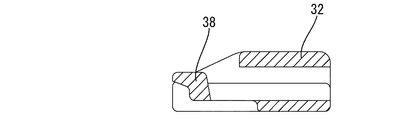
また、一方のアーム部32には、弾性ロック片38が形成されている。この弾性ロック片38は比較的操作部31に近い位置に配されており、レバー30が嵌合位置まで回動させると、この弾性ロック片38がコネクタハウジング10のロック突起24に係止し、もってレバー30が嵌合位置において遊動不能にロックされる。また、ロック状態から弾性ロック片38を弾性撓みさせてロック突起24から外すと、レバー30は初期位置へ向けて回動できるようになる。
【0020】
次に、本実施形態の作用を説明する。
レバー30を組付ける際には、図1に示すように、操作部31が上を向くようにしたレバー30を、コネクタハウジング10に対して後方から接近させる。このとき、コネクタハウジング10の支持軸21にはアーム部32のガイド斜面35が対向している。レバー30を接近させてアーム部32を収容空間15内に進入させると、ガイド斜面35が支持軸21の突出端に当接し、これ以降はアーム部32の進入に伴ってガイド斜面35が支持軸21に摺接するとともに、そのガイド斜面35の勾配によって支持壁14が外側へ押し広げられる。そして、軸受孔33が支持軸21に至ると、支持壁14が内側へ弾性復帰するとともに軸受孔33が支持軸21に嵌合される。以上により、レバー30がコネクタハウジング10に対して回動可能に支持される。
【0021】
この後、操作部31を摘んでレバー30を下向きに回動させると、レバー30が初期位置に至り、図2に示すようにレバー30は遊動規制された係止状態とされる。この状態では、カム溝34の入口34Eが、前方を向き、支持壁14の逃がし部18を介してコネクタハウジング10の前方へ開放された状態で相手側コネクタMのカムピンMpを待ち受ける。
相手側コネクタMとの嵌合の際には、レバー30を初期位置にした状態で、相手側コネクタMのフード部Mfを筒状嵌合部12内に嵌入させるとともに、カムピンMpを逃がし溝17及び逃がし部18を通してカム溝34の入口34Eに進入させる(図2を参照)。この後、操作部31を摘んでレバー30を上方へ回動させる。レバー30の回動に伴い、カムピンMpとカム溝34との係合によりカム作用が発揮され、相手側コネクタMがコネクタハウジング10に引き込まれる。そして、レバー30が嵌合位置に達すると、相手側コネクタMが正規嵌合されるとともに、レバー30が嵌合位置にロックされる(図3を参照)。
【0022】
尚、相手側コネクタMを外す際には、弾性ロック片38によるロックを解除してレバー30を初期位置へ回動させれば、カム作用により、相手側コネクタMがコネクタハウジング10から前方へ戻される。そして、レバー30が初期位置に達したところで、相手側コネクタMを引っ張れば、カムピンMpがカム溝34から抜き取られる。
上述のように本実施形態においては、コネクタハウジング10の筒状嵌合部12にアーム部32の外側面と対応するように支持壁14を形成し、アーム部32の軸受孔33を嵌合させてレバー30を回動可能に支持するための手段である支持軸21を、その支持壁14の内側面から内向きに突出する形態で形成しているので、支持軸21は、アーム部32の軸受孔33に対して外側から嵌合された状態となっている。これにより、カムピンMpとカム溝34の係合によってアーム部32が外向きに拡がろうとした場合、その変位の方向は、軸受孔33を支持軸21の突出端側から基端側へ向かわせる方向となり、したがって、軸受孔33と支持軸21との係止代が小さくなることはない。このように本実施形態のレバー式コネクタFでは、アーム部32が外向きに拡がることに起因して支持軸21による軸受孔33の支持機能の信頼性が低下する、ということはない。
【0023】
また、左右一対のアーム部32は支持壁14の内側面に概ね当接した状態となっている。したがって、カムピンMpとカム溝34との係合によってアーム部32に対してこれを外側へ拡げようとする力が作用しても、アーム部32は、支持壁14の内側面に当接することにより、拡がるように変位することが規制されている。
また、アーム部32の外側面には、軸受孔33の孔縁からアーム部32の外周縁に向かってアーム部32の板厚が薄くなるように傾斜したガイド斜面35を形成し、軸受孔33を支持軸21に組み付けるときには、支持軸21をガイド斜面35と対応させるようになっている。これにより、アーム部32の外周縁が支持軸21と干渉することが回避され、組付け作業性が良くなっている。しかも、ガイド斜面35は、軸受孔33からアーム部32の外周縁に向かって幅が広がる台形状になっているので、レバー30が支持軸21に対して上下方向に位置ずれしても、支持軸21を確実に軸受孔33へ遊動することができる。
【0024】
[他の実施形態]
本発明は上記記述及び図面によって説明した実施形態に限定されるものではなく、例えば次のような実施態様も本発明の技術的範囲に含まれ、さらに、下記以外にも要旨を逸脱しない範囲内で種々変更して実施することができる。
(1)上記実施形態では雌端子金具が収容される雌コネクタに適用した例を説明したが、本発明は、雄端子金具が組み付けられる雄コネクタにも適用することができる。
【0025】
(2)上記実施形態では一対のアーム部を支持壁の内側面に概ね当接させる構成としたが、本発明によれば、アーム部の外側面と支持壁の内側面との間に隙間を空けてもよい。この場合、支持軸に基端側が大径となるように段差を設けてその段差部にアーム部の外側面における軸受孔の孔縁部を係止させれば、レバーにの軸方向に遊動を規制することができる。
(3)上記実施形態では一対のアーム部がコネクタハウジングの外側面に対して概ね当接する構成としたが、本発明によれば、アーム部の内側面とコネクタハウジングの外側面との間に隙間が空くようにしてもよい。
【0026】
(4)上記実施形態では軸受孔をアーム部の外側面から内側面まで貫通する形態としたが、本発明によれば、軸受孔を、アーム部の内側面まで貫通させず、アーム部の外側面を凹ませた形態としてもよい。
【図面の簡単な説明】
【図1】実施形態1においてレバーをコネクタハウジングから外した状態をあらわす側面図
【図2】レバーをコネクタハウジングに組み付けた状態の一部切欠側面図
【図3】レバーを初期位置から嵌合位置へ回動させた状態の一部切欠側面図
【図4】コネクタハウジングの正面図
【図5】図4のA−A断面図
【図6】レバーが初期位置にある状態における図4のA−A断面図
【図7】コネクタハウジングの底面図
【図8】レバーの断面図
【図9】レバーの正面図
【図10】図8のB−B断面図
【図11】図9のC−C断面図
【図12】図8のD−D断面図
【符号の説明】
F…レバー式コネクタ
M…相手側コネクタ
Mp…カムピン
10…コネクタハウジング
14…支持壁
21…支持軸
30…レバー
31…操作部
32…アーム部
33…軸受孔
34…カム溝
35…ガイド斜面[0001]
BACKGROUND OF THE INVENTION
The present invention relates to a lever type connector.
[0002]
[Prior art]
Conventionally, there is a lever type connector disclosed in Japanese Utility Model Laid-Open No. 3-126379. This consists of a connector housing and a lever formed with a pair of arm portions projecting at both ends of the operation portion. The arm portion is made to correspond to the outer surface of the connector housing, and the bearing hole of the arm portion is formed outside the connector housing. The lever is rotatably supported by the connector housing so as to be fitted to the side support shaft. When the lever is rotated with the cam pin protruding from the outer surface of the mating connector engaged with the cam groove formed on the inner surface of the arm portion, the cam action is caused by the engagement of the cam groove and the cam pin. The mating connector is pulled into the connector housing to be in a fitted state.
[0003]
[Problems to be solved by the invention]
As described above, in the lever-type connector that engages the cam pin on the outer surface of the mating connector with the cam groove on the inner surface of the arm portion, let the cam pin and cam groove engage to expand this outward. That is, a force for separating the arm portion from the outer surface of the connector housing acts.
However, in the conventional lever type connector, the support shaft into which the bearing hole of the arm portion is fitted projects outward from the outer surface of the connector housing. Therefore, as the arm portion is displaced so as to expand outward, the bearing hole is displaced from the base end side of the support shaft to the protruding end side, that is, in a direction away from the support shaft. There is a concern that the reliability of the support function will be reduced.
[0004]
The present invention has been made in view of the above circumstances, and an object thereof is to ensure the reliability of the lever support function even when the arm portion is expanded outwardly due to the engagement between the cam pin and the cam groove.
[0005]
[Means for Solving the Problems]
The invention according to
[0006]
According to a second aspect of the present invention, in the first aspect of the invention, the outer surfaces of the pair of arm portions are substantially in contact with the inner surface of the support wall.
According to a third aspect of the invention, in the invention of the first or second aspect, on the outer surface of the arm portion, the plate thickness of the arm portion decreases from the hole edge of the bearing hole toward the outer peripheral edge of the arm portion. It was set as the structure which formed the inclined guide slope so that it might become.
[0007]
[Action and effect of the invention]
[Invention of Claim 1]
Since the support shaft that protrudes inward from the support wall of the connector housing is fitted to the bearing hole of the arm portion from the outside, the arm portion faces outward by the engagement of the cam pin and the cam groove. When the expansion is attempted, the direction of displacement is the direction in which the bearing hole is displaced from the protruding end side to the base end side of the support shaft, and the locking allowance between the bearing hole and the support shaft is not reduced. Therefore, the reliability of the support function of the bearing hole by the support shaft does not decrease due to the arm portion expanding outward.
[0008]
[Invention of claim 2]
Since the pair of arm portions are generally in contact with the inner surface of the support wall, even if a force is applied to the arm portion to expand outward due to the engagement between the cam pin and the cam groove, the arm portion There is no displacement to expand.
[Invention of claim 3]
A guide slope is formed on the outer surface of the arm portion so that the plate thickness of the arm portion decreases from the hole edge of the bearing hole toward the outer periphery of the arm portion. If the shaft is made to correspond to the guide slope, the outer peripheral edge of the arm portion is prevented from interfering with the support shaft, and the assembling workability is improved.
[0009]
DETAILED DESCRIPTION OF THE INVENTION
[Embodiment 1]
A first embodiment of the present invention will be described below with reference to FIGS.
The lever type connector F of the present embodiment is applied to a female connector that accommodates a female terminal fitting (not shown), and includes a
[0010]
First, the
[0011]
The
[0012]
Further, the tubular
[0013]
The pair of left and
[0014]
Further, the
[0015]
Further, the connecting
[0016]
Next, the
[0017]
Further, a non-circular arc-shaped
[0018]
In addition, a
Furthermore, an arc-shaped first
[0019]
Further, an
[0020]
Next, the operation of this embodiment will be described.
When the
[0021]
Thereafter, when the operating
When fitting with the mating connector M, the hood portion Mf of the mating connector M is fitted into the cylindrical
[0022]
When the mating connector M is removed, if the lock by the
As described above, in the present embodiment, the
[0023]
In addition, the pair of left and
Further, a
[0024]
[Other Embodiments]
The present invention is not limited to the embodiment described with reference to the above description and drawings. For example, the following embodiments are also included in the technical scope of the present invention, and further, within the scope not departing from the gist of the invention other than the following. Various modifications can be made.
(1) Although the example applied to the female connector in which the female terminal fitting is accommodated has been described in the above embodiment, the present invention can also be applied to a male connector to which the male terminal fitting is assembled.
[0025]
(2) In the above embodiment, the pair of arm portions are configured to substantially contact the inner side surface of the support wall. However, according to the present invention, a gap is provided between the outer side surface of the arm portion and the inner side surface of the support wall. It may be vacant. In this case, if the support shaft is provided with a step so that the base end side has a large diameter, and the hole edge portion of the bearing hole on the outer surface of the arm portion is engaged with the step portion, the lever is free to move in the axial direction. Can be regulated.
(3) In the above embodiment, the pair of arm portions are configured to substantially abut against the outer surface of the connector housing. However, according to the present invention, a gap is provided between the inner surface of the arm portion and the outer surface of the connector housing. May be free.
[0026]
(4) In the above embodiment, the bearing hole is penetrated from the outer side surface to the inner side surface of the arm portion. However, according to the present invention, the bearing hole is not penetrated to the inner side surface of the arm portion. It is good also as a form where the side surface was dented.
[Brief description of the drawings]
FIG. 1 is a side view showing a state in which a lever is detached from a connector housing in
F ... lever type connector M ... mating connector Mp ...
Claims (3)
前記コネクタハウジングは、後端がハウジング本体に支持されて前方へ延出した形態の筒状嵌合部と、前記筒状嵌合部の前端部から前記筒状嵌合部の外側面に沿って後方へ片持ち状に延出する形態の支持壁とを有しており、
前記筒状嵌合部の外側面と前記支持壁の内側面に前記アーム部を対応させるとともに、前記アーム部に形成した軸受孔を前記支持壁の内側面に内向きに突出する形態で設けた支持軸に嵌合させることで前記レバーを前記コネクタハウジングに回動可能に支持し、
相手側コネクタの外側面に突成されて前方から進入したカムピンを、前記アーム部の内側面に形成したカム溝に対して前記支持軸及び前記軸受孔よりも前方の位置で係合させた状態で前記レバーを回動させることで、前記カム溝と前記カムピンとの係合によるカム作用により、前記相手側コネクタを前記コネクタハウジングに引き込んで嵌合状態とするようになっていることを特徴とするレバー式コネクタ。Comprising a connector housing and a lever formed by projecting a pair of arm portions at both ends of the operation portion;
The connector housing includes a cylindrical fitting portion having a rear end supported by the housing body and extending forward, and a front end portion of the cylindrical fitting portion along an outer surface of the cylindrical fitting portion. And a support wall that extends in a cantilevered manner to the rear,
The arm portion is made to correspond to the outer side surface of the cylindrical fitting portion and the inner side surface of the support wall, and a bearing hole formed in the arm portion is provided in a form protruding inward on the inner side surface of the support wall . The lever is rotatably supported by the connector housing by being fitted to a support shaft,
State the cam pins entering from the front it is突成the outer surface of the mating connector, is engaged in a position ahead of the support shaft and the bearing hole for the cam groove formed on the inner surface of the arm portion by in by rotating the lever, the cam action due to engagement with the cam pin and the cam groove, and characterized in that the mating connector is adapted to the fitted state by drawing the connector housing Lever type connector.
Priority Applications (3)
| Application Number | Priority Date | Filing Date | Title |
|---|---|---|---|
| JP2001221521A JP3775255B2 (en) | 2001-07-23 | 2001-07-23 | Lever type connector |
| DE10232969A DE10232969B4 (en) | 2001-07-23 | 2002-07-19 | Connector with locking lever |
| US10/201,113 US6623286B2 (en) | 2001-07-23 | 2002-07-22 | Lever-type connector |
Applications Claiming Priority (1)
| Application Number | Priority Date | Filing Date | Title |
|---|---|---|---|
| JP2001221521A JP3775255B2 (en) | 2001-07-23 | 2001-07-23 | Lever type connector |
Publications (2)
| Publication Number | Publication Date |
|---|---|
| JP2003036929A JP2003036929A (en) | 2003-02-07 |
| JP3775255B2 true JP3775255B2 (en) | 2006-05-17 |
Family
ID=19055174
Family Applications (1)
| Application Number | Title | Priority Date | Filing Date |
|---|---|---|---|
| JP2001221521A Expired - Lifetime JP3775255B2 (en) | 2001-07-23 | 2001-07-23 | Lever type connector |
Country Status (1)
| Country | Link |
|---|---|
| JP (1) | JP3775255B2 (en) |
Families Citing this family (3)
| Publication number | Priority date | Publication date | Assignee | Title |
|---|---|---|---|---|
| JP4200169B2 (en) | 2006-09-12 | 2008-12-24 | 日本航空電子工業株式会社 | connector |
| JP5227233B2 (en) * | 2009-03-31 | 2013-07-03 | 矢崎総業株式会社 | LIF connector |
| JP6332074B2 (en) * | 2015-02-16 | 2018-05-30 | 住友電装株式会社 | Lever type connector |
-
2001
- 2001-07-23 JP JP2001221521A patent/JP3775255B2/en not_active Expired - Lifetime
Also Published As
| Publication number | Publication date |
|---|---|
| JP2003036929A (en) | 2003-02-07 |
Similar Documents
| Publication | Publication Date | Title |
|---|---|---|
| EP1079473B1 (en) | Lever type connector | |
| JP5029872B2 (en) | Lever type connector | |
| JP4395784B2 (en) | Lever type connector | |
| EP1734619B1 (en) | A connector and connector assembly of the movable member type | |
| JP6441866B2 (en) | Lever type connector | |
| JP5666180B2 (en) | Lever type connector | |
| JP3472686B2 (en) | Slide mating type connector | |
| EP1830435B1 (en) | A lever-type connector and connector assembly | |
| CN111834836B (en) | Connector with grommet | |
| WO2018008598A1 (en) | Lock device production method | |
| JP7065057B2 (en) | Lever type connector | |
| US6623286B2 (en) | Lever-type connector | |
| JP3775255B2 (en) | Lever type connector | |
| WO1995012906A1 (en) | Lever type connector | |
| JPH0513129A (en) | Connector with lever | |
| JP5136363B2 (en) | Lever type connector | |
| JP4924901B2 (en) | Lock structure and connector | |
| JPH09147973A (en) | Lever type connector | |
| JP7453067B2 (en) | connector set | |
| JPH11102747A (en) | Lever type connector | |
| JP4442502B2 (en) | Lever type connector | |
| JP4548198B2 (en) | Lever type connector | |
| JP4457955B2 (en) | Lever type connector | |
| CN111834837A (en) | Connector fitted with grommet | |
| JP4407565B2 (en) | Lever type connector |
Legal Events
| Date | Code | Title | Description |
|---|---|---|---|
| A621 | Written request for application examination |
Free format text: JAPANESE INTERMEDIATE CODE: A621 Effective date: 20040426 |
|
| A977 | Report on retrieval |
Free format text: JAPANESE INTERMEDIATE CODE: A971007 Effective date: 20051006 |
|
| A131 | Notification of reasons for refusal |
Free format text: JAPANESE INTERMEDIATE CODE: A131 Effective date: 20051101 |
|
| A521 | Written amendment |
Free format text: JAPANESE INTERMEDIATE CODE: A523 Effective date: 20051226 |
|
| TRDD | Decision of grant or rejection written | ||
| A01 | Written decision to grant a patent or to grant a registration (utility model) |
Free format text: JAPANESE INTERMEDIATE CODE: A01 Effective date: 20060131 |
|
| A61 | First payment of annual fees (during grant procedure) |
Free format text: JAPANESE INTERMEDIATE CODE: A61 Effective date: 20060213 |
|
| R150 | Certificate of patent or registration of utility model |
Ref document number: 3775255 Country of ref document: JP Free format text: JAPANESE INTERMEDIATE CODE: R150 Free format text: JAPANESE INTERMEDIATE CODE: R150 |
|
| FPAY | Renewal fee payment (event date is renewal date of database) |
Free format text: PAYMENT UNTIL: 20100303 Year of fee payment: 4 |
|
| FPAY | Renewal fee payment (event date is renewal date of database) |
Free format text: PAYMENT UNTIL: 20110303 Year of fee payment: 5 |
|
| FPAY | Renewal fee payment (event date is renewal date of database) |
Free format text: PAYMENT UNTIL: 20120303 Year of fee payment: 6 |
|
| FPAY | Renewal fee payment (event date is renewal date of database) |
Free format text: PAYMENT UNTIL: 20120303 Year of fee payment: 6 |
|
| FPAY | Renewal fee payment (event date is renewal date of database) |
Free format text: PAYMENT UNTIL: 20130303 Year of fee payment: 7 |
|
| FPAY | Renewal fee payment (event date is renewal date of database) |
Free format text: PAYMENT UNTIL: 20140303 Year of fee payment: 8 |
|
| EXPY | Cancellation because of completion of term |