JP3771195B2 - Weight measuring noise removing device and weight measuring noise removing method - Google Patents
Weight measuring noise removing device and weight measuring noise removing method Download PDFInfo
- Publication number
- JP3771195B2 JP3771195B2 JP2002143110A JP2002143110A JP3771195B2 JP 3771195 B2 JP3771195 B2 JP 3771195B2 JP 2002143110 A JP2002143110 A JP 2002143110A JP 2002143110 A JP2002143110 A JP 2002143110A JP 3771195 B2 JP3771195 B2 JP 3771195B2
- Authority
- JP
- Japan
- Prior art keywords
- frequency
- filter
- noise
- notches
- weight measurement
- Prior art date
- Legal status (The legal status is an assumption and is not a legal conclusion. Google has not performed a legal analysis and makes no representation as to the accuracy of the status listed.)
- Expired - Fee Related
Links
- 238000000034 method Methods 0.000 title claims description 21
- 238000005259 measurement Methods 0.000 claims description 52
- 230000008859 change Effects 0.000 claims description 46
- 230000000737 periodic effect Effects 0.000 claims description 36
- 238000012546 transfer Methods 0.000 claims description 24
- 238000005303 weighing Methods 0.000 claims description 20
- 238000001514 detection method Methods 0.000 claims description 9
- 230000004044 response Effects 0.000 claims description 7
- 238000001914 filtration Methods 0.000 claims description 4
- 238000004364 calculation method Methods 0.000 claims description 2
- 238000000691 measurement method Methods 0.000 claims 2
- 230000006870 function Effects 0.000 description 19
- 238000005070 sampling Methods 0.000 description 11
- 238000010586 diagram Methods 0.000 description 8
- 238000001228 spectrum Methods 0.000 description 7
- 238000007796 conventional method Methods 0.000 description 4
- 230000032683 aging Effects 0.000 description 1
- 230000002238 attenuated effect Effects 0.000 description 1
- 230000008901 benefit Effects 0.000 description 1
- 238000006243 chemical reaction Methods 0.000 description 1
- 230000000694 effects Effects 0.000 description 1
- 238000012544 monitoring process Methods 0.000 description 1
- 230000008569 process Effects 0.000 description 1
- 238000012545 processing Methods 0.000 description 1
- 238000013139 quantization Methods 0.000 description 1
Images


Classifications
-
- H—ELECTRICITY
- H03—ELECTRONIC CIRCUITRY
- H03H—IMPEDANCE NETWORKS, e.g. RESONANT CIRCUITS; RESONATORS
- H03H17/00—Networks using digital techniques
- H03H17/02—Frequency selective networks
- H03H17/0248—Filters characterised by a particular frequency response or filtering method
- H03H17/025—Notch filters
-
- G—PHYSICS
- G01—MEASURING; TESTING
- G01G—WEIGHING
- G01G23/00—Auxiliary devices for weighing apparatus
- G01G23/06—Means for damping oscillations, e.g. of weigh beams
- G01G23/10—Means for damping oscillations, e.g. of weigh beams by electric or magnetic means
-
- G—PHYSICS
- G01—MEASURING; TESTING
- G01G—WEIGHING
- G01G3/00—Weighing apparatus characterised by the use of elastically-deformable members, e.g. spring balances
- G01G3/12—Weighing apparatus characterised by the use of elastically-deformable members, e.g. spring balances wherein the weighing element is in the form of a solid body stressed by pressure or tension during weighing
- G01G3/14—Weighing apparatus characterised by the use of elastically-deformable members, e.g. spring balances wherein the weighing element is in the form of a solid body stressed by pressure or tension during weighing measuring variations of electrical resistance
- G01G3/142—Circuits specially adapted therefor
- G01G3/147—Circuits specially adapted therefor involving digital counting
-
- H—ELECTRICITY
- H03—ELECTRONIC CIRCUITRY
- H03H—IMPEDANCE NETWORKS, e.g. RESONANT CIRCUITS; RESONATORS
- H03H17/00—Networks using digital techniques
- H03H17/02—Frequency selective networks
- H03H17/0294—Variable filters; Programmable filters
Landscapes
- Physics & Mathematics (AREA)
- Engineering & Computer Science (AREA)
- Computer Hardware Design (AREA)
- Mathematical Physics (AREA)
- General Physics & Mathematics (AREA)
- Measurement Of Mechanical Vibrations Or Ultrasonic Waves (AREA)
Description
【0001】
【発明の属する技術分野】
本発明は、デジタル・フィルタを用いた重量測定用ノイズ除去装置および重量測定用ノイズ除去方法に関する。
【0002】
【従来の技術】
歪みゲージ式のロードセルやフォースバランスなどの荷重検出器から出力される計量信号には、計量系に起因する多種多様なノイズが含まれている。搬送系の荷重測定を行う場合には、例えば、ベルトコンベヤーを駆動するモーターや搬送ローラなどの回転系振動に起因するノイズや、商用電源などに起因する電気的なノイズなどが、定周期性の振動ノイズとして計量信号に重畳しているのが一般的である。また、構造物を含む計量系は当該構造物の固有振動数をもつ。この固有振動数を含む帯域の外部振動が計量系に作用したとき、その外部振動はその固有振動数付近で増幅され、振動ノイズとなって計量信号中に出現する。以下、定周期性の振動ノイズと固有振動数に起因する振動ノイズとを合わせて「定周期振動ノイズ」と呼ぶ。
【0003】
近年、その定周期振動ノイズの除去のために、経年変化や周辺環境などの影響を受け難く、フィルタ特性を比較的容易に変更できるデジタル・フィルタが採用されており、デジタル・フィルタの中でも、特に安定性に優れた有限インパルス応答(FIR)型フィルタが好まれて使用される。
【0004】
また、従来は、計量信号から定周期振動ノイズを除去するため、その定周期振動ノイズに対応する周波数帯域において十分な減衰量を得られるローパスフィルタが採用されていた。この種のローパスフィルタを用いて、定周期振動ノイズを比較的短時間で減衰させる従来技術としては、特公昭63−052684号公報記載の「定周期振動波除去方法」が知られている。この定周期振動波除去方法は、定周期振動ノイズの略整数周期分に相当するサンプリング数をタップ数とした移動平均フィルタを採用している。しかしながら、そのタップ数は、ノイズの周期(周波数)に応じて変動し得るため、その移動平均フィルタの遅れ時間が変動し得るという問題がある。また、定周期振動ノイズの整数周期分に相当するサンプリング数にタップ数が一致しない場合は、その不一致に相当する誤差が出現するという問題もある。
【0005】
また、その定周期振動波除去方法では、周波数が相対的に高い電源ノイズや、それが相対的に低い機械振動ノイズのように、互いに周波数の異なる複数の定周期振動ノイズに対処するために、各ノイズに対応した移動平均フィルタを多段で用意しなければならない。1段のフィルタで複数のノイズ振動を減衰させるには、当該フィルタが、それらノイズ振動に対応した複数の阻止域(ノッチ)をもつ必要がある。
【0006】
しかしながら、搬送計量系の場合であって、被計量物の搬送速度が可変であるがために、その搬送計量系を構成するモーターやローラの振動周波数が搬送速度に合わせて変化する場合では、定周期振動ノイズの周波数変動に対応するために複数段のフィルタを用意しなければならなかった。また、例えばモーターやローラに起因するノイズのようにその周波数が変動する場合と、電源周波数に起因するノイズのようにその周波数が殆ど不変の場合とにそれぞれ対応した複数種のフィルタ特性を用意する必要があるのが実状であった。
【0007】
【発明が解決しようとする課題】
以上の問題や実状などに鑑みて本発明が目的とするところは、定周期振動ノイズの周波数変動に対してフィルタ特性を追従して変更させ得て、周波数変動する定周期振動ノイズを高精度に減衰させ得るノイズ除去装置およびノイズ除去方法を提供する点にある。
【0008】
【課題を解決するための手段】
上記課題を解決するため、請求項1に係る発明は、被計量物の重量を検出して得た信号をデジタル化した計量信号に含まれる定周期振動ノイズを除去する重量測定用ノイズ除去装置であって、前記計量信号の周波数成分を複数のノッチで減衰させるフィルタリングを、可変のフィルタ係数を用いて実行する帯域通過フィルタと、前記フィルタ係数の系列を算出して前記帯域通過フィルタに供給する係数制御部と、を備え、前記帯域通過フィルタは、前記複数のノッチを含む周波数特性を有すると共に、当該帯域通過フィルタの伝達関数は、前記複数のノッチに対応する根をもつ複数の因子の積を含んで構成されており、前記係数制御部は、前記複数のノッチの中から指定されたノッチに対応する根を含む因子の当該根の周波数成分を変更する周波数変更手段と、前記帯域通過フィルタの伝達関数を構成する複数の因子の積を多項式に展開する展開手段と、前記多項式に基づいて前記フィルタ係数の系列を算出する係数算出手段と、を備えることを特徴としたものである。
【0009】
請求項2に係る発明は、請求項1記載の重量測定用ノイズ除去装置であって、前記帯域通過フィルタは有限インパルス応答(FIR)型のデジタル・フィルタである。
【0010】
請求項3に係る発明は、請求項1または2記載の重量測定用ノイズ除去装置であって、前記周波数変更手段で変更される周波数成分の変化量を手動で入力せしめるデータ入力部を更に備えたものである。
【0011】
請求項4に係る発明は、請求項1〜3の何れか1項に記載の重量測定用ノイズ除去装置であって、前記計量信号の周波数特性を算出するフーリエ変換部と、前記周波数特性を解析して当該計量信号に含まれる定周期振動ノイズの周波数帯域の変化量を検出する変動検出部と、前記変動検出部で検出された当該変化量に基づいて前記周波数変更手段で変更される当該周波数成分の変化量を指定する制御部と、を更に備えたものである。
【0012】
次に、請求項5に係る発明は、被計量物の重量を検出して得た信号をデジタル化した計量信号に含まれる定周期振動ノイズを除去する重量測定用ノイズ除去方法であって、(a)帯域通過フィルタ用のフィルタ係数の系列を算出する工程と、(b)前記計量信号の周波数成分を複数のノッチで減衰させるフィルタリングを、前記フィルタ係数の系列をもつ帯域通過フィルタによって実行する工程と、を備え、前記帯域通過フィルタは、前記複数のノッチを含む周波数特性を有すると共に、当該帯域通過フィルタの伝達関数は、前記複数のノッチに対応する根をもつ複数の因子の積を含んで構成されており、前記工程(a)は、(a−1)前記複数のノッチの中から指定されたノッチに対応する根を含む因子の当該根の周波数成分を変更する工程と、(a−2)前記帯域通過フィルタの伝達関数を構成する複数の因子の積を多項式に展開する工程と、(a−3)前記多項式に基づいて前記フィルタ係数の系列を算出する工程と、を備える、ことを特徴としたものである。
【0013】
請求項6に係る発明は、請求項5記載の重量測定用ノイズ除去方法であって、前記帯域通過フィルタは有限インパルス応答(FIR)型のデジタル・フィルタである。
【0014】
請求項7に係る発明は、請求項5または6記載の重量測定用ノイズ除去方法であって、(c)前記工程(a−1)で変更される周波数成分の変化量を手動で入力せしめる工程、を更に備えたものである。
【0015】
そして、請求項8に係る発明は、請求項5〜7の何れか1項に記載の重量測定用ノイズ除去方法であって、(e)前記計量信号の周波数特性を算出するフーリエ変換工程と、(f)前記周波数特性を解析して当該計量信号に含まれる定周期振動ノイズの周波数帯域の変化量を検出する工程と、(g)前記工程(f)で検出された当該変化量に基づいて前記工程(a−1)で変更される当該周波数成分の変化量を指定する工程と、を更に備えたものである。
【0016】
【発明の実施の形態】
図1は、本発明の実施の形態に係る重量測定用のノイズ除去装置1を示す機能ブロック図である。
【0017】
このノイズ除去装置1は、計量装置3から出力された測定信号msを増幅するアンプ10、アナログ・フィルタ11、A/D変換器(ADC)12、デジタル・フィルタ14、係数制御部13およびデータ入力部15を備えて構成されている。また、計量装置(ロードセル)3は、計量系2から受けた重量を測定して得た測定信号msをノイズ除去装置1に出力する。
【0018】
前記アンプ10は、計量装置3から入力した測定信号msを増幅して得た増幅信号MSをアナログ・フィルタ11に出力する。アナログ・フィルタ11は、その増幅信号MSから不要な高域成分を除去したアナログ信号Asを出力する。A/D変換器12は、アナログ・フィルタ11から入力するアナログ信号Asに対して、所定のサンプリング周期でサンプリングし、所定の量子化ビット数で量子化したデジタル信号(以下、計量信号と呼ぶ。)D(n)(n:整数)をデジタル・フィルタ14と係数制御部13とにそれぞれ出力する。
【0019】
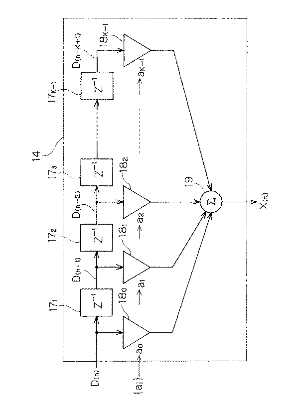
図2は、その計量信号D(n)をフィルタリングする有限インパルス応答(FIR)型のデジタル・フィルタ14を示す概略構成図である。
【0020】
このデジタル・フィルタ14は、係数制御部13から供給されたフィルタ係数の系列{ai}(i=0,1,2,…,K−1)を用いたフィルタリング機能を有する。デジタル・フィルタ14は、Kタップ(K:2以上の整数)の帯域通過フィルタ(ローパスフィルタ)であり、入力する一連の計量信号D(n)を1周期遅延させる遅延素子171,172,173,…,17K-1と、係数乗算器180,181,…,18K-1と、加算器19とで構成されている。(K−1)個の遅延素子171〜17K-1は、Dフリップ・フロップなどで構成され、(K−1)段で直列接続されている。これら遅延素子171〜17K-1は、サンプリング周期Tでパルス(図示せず)が供給される度に、前段から入力する計量信号D(s)(s=n〜n−K+1)を取り込み保持して出力する。また、係数乗算器180〜18K-1は、それぞれ、係数制御部13から供給されたフィルタ係数a0〜aK-1を用いて係数乗算処理を行う。各係数乗算器18m(m=0〜K−1)は、入力信号D(n−m)にフィルタ係数amを乗算して加算器19に出力する。そして、加算器19は、係数乗算器180〜18K-1から伝達した全ての信号を加算して得た積和信号X(n)を出力する。
【0021】
このデジタル・フィルタ14のz変換形式の伝達関数H(z)は次式(1)の通りである。
【0022】
【数1】
前記デジタル・フィルタ14は、複数のノッチ(阻止域)を含む周波数特性を有するノッチ・フィルタである。一般に、デジタル・フィルタの通過域の振幅特性は略一定になることが望ましく、そのノッチは等リップル特性をもつことが望ましい。等リップル特性をもつデジタル・フィルタの設計法としてはRemezアルゴリズムが知られている。図3は、Remezアルゴリズムによって設計されたデジタル・フィルタ14の振幅特性を示すグラフである。ここで、同グラフの縦軸は信号の減衰量(ゲイン)を示し、その横軸は規格化周波数(ωT/π)を示している。その振幅特性は、次式(2)に示す伝達関数H(ej ω T)の絶対値|H(ej ω T)|に従って算出される。
【0024】
【数2】
上式(2)中、j2=−1、ωは角周波数、Tはサンプリング周期を表している。
【0026】
図3に示す通り、その振幅特性は、減衰量が大きい部分にノッチ16,16,…を形成する。デジタル・フィルタ14の伝達関数H(z)は、次式(3)に示すように各ノッチ16,…の一部または全部に対応するゼロ点の複素根λ1,λ2,…,λM(M:根の数)を有している。ここで、「ゼロ点」とは、伝達関数H(z)がゼロ値をとるときのz平面の点を意味しており、計量時の基準点を意味するものではない。
【0027】
【数3】
また、前記伝達関数H(z)は、複素根λ1,λ2,…,λMを含む因子(z-1−λ1),(z-1−λ2),…,(z-1−λM)の積からなり、因数分解された形をもつ。図4は、上式(3)で表現される伝達関数H(z)の複素根の配置を示すグラフである。同グラフの横軸は複素数zの実数部を示し、その縦軸は複素数zの虚数部を示している。また、全ての複素根λ1,λ2,…,λMが単位円24上に配置されている。
【0029】
尚、本実施の形態では、前記伝達関数H(z)は、複数の因子(z-1−λ1),(z-1−λ2),…,(z-1−λM)の積だけで構成されるが、本発明ではこれに限らず、その積を含むものであればよい。例えば、伝達関数H(z)がその分母に極を含む形を有していてもよい。
【0030】
前記複素根λk(k=1,2,…,M)は、極座標で表現されると、次式(4)のようになる。
【0031】
【数4】
上式(4)中、rkは複素根λkの振幅(絶対値)、Re(λk)は複素根λkの実数部、Im(λk)は複素根λkの虚数部を表している。また、上式(4)中、θkは、図4に示すグラフの原点回りの角度を意味し、本実施の形態では、周波数成分ωとサンプリング周期Tとの積ω×Tに等しい。デジタル・フィルタ14は、その積ω×Tを−π〜πの区画で規格化した規格化周波数(ω×T/π)の−1〜+1の区画でゼロ点を有するが、図4に示すように、ゼロ点は、実軸24Rに対して軸対称の位置に存在するため、図3に示すグラフでは、規格化周波数の0〜+1の区画に限定した振幅特性が示されている。
【0033】
従来、ノッチ16に対応する周波数(以下、ノッチ周波数と呼ぶ。)を変える方法としては、デジタル・フィルタのタップ数を変更する方法、或いは、サンプリング周期Tを変更する方法の何れかが採用されていた。しかしながら、これら従来法では、周波数変動する定周期振動ノイズに対して実際上対応することが困難であった。また、サンプリング周期Tを変更する従来法を採用して、サンプリング周期Tを、定周期振動ノイズの変動に合わせて連続的に変化させることは現実的ではない。たとえサンプリング周期Tの連続的な変化が実現可能であるとしても、その変化によって、例えば商用電源に起因するノイズのように、周波数変動しないノイズに対応したノッチ周波数が一緒に変化してしまう。以下に説明するように、本発明では、複数のノッチ16,16,…の中から任意のノッチ16を選択し、選択した当該ノッチ16のみを変化させることが可能である。
【0034】
図5は、図1に示した係数制御部13の概略構成を示す機能ブロック図である。この係数制御部13は、ノッチ選択部20、周波数変更手段21、展開手段22および係数算出手段23を備えて構成されている。周波数変更手段21は、ノッチ選択部20もしくはデータ入力部15から、ノッチ16とこのノッチ16に対応するノッチ周波数の変化量δωとを指定される。周波数変更手段21は、複数のノッチ16,16,…の中から指定されたノッチ16に対応する複素根λkの周波数成分ωkを(ωk+δω)に変更する。また、周波数変更手段21は、変更後の周波数成分(ωk+δω)を用いて、変更後の複素根λk’を生成して次段の展開手段22に出力する。その変更後の複素根λk’は、次式(5)のようになる。
【0035】
【数5】
次に、展開手段22は、その変更後の複素根λk’を用いて再構成されるデジタル・フィルタ14の伝達関数H(z)を多項式に展開する。再構成された伝達関数H(z)は次式(6A)のようになり、この式(6A)が多項式に展開されると次式(6B)のようになる。
【0037】
【数6】
次に、係数算出手段23は、前記展開手段22から出力された上式(6B)の多項式の展開情報に基づいてフィルタ係数の新たな系列{ai’}を得て出力する。従って、変更前のフィルタ係数の系列{ai}から、新たな系列{ai’}が生成され、デジタル・フィルタ14に出力される。そして、デジタル・フィルタ14においては、図2に示した係数乗算器180〜18K-1は、係数制御部13から伝達した更新後のフィルタ係数a0’〜aK-1’を保持し、これらフィルタ係数a0’〜aK-1’と入力信号D(n)〜D(n−K+1)とを乗算して加算器19に出力する。加算器19は、係数乗算器180〜18K-1から出力された全信号を加算し、上記定周期振動ノイズが除去された計量信号X(n)を出力する。
【0039】
このように上記ノイズ除去装置1によれば、周波数変動する定周期振動ノイズに対して、デジタル・フィルタ14の複数のノッチ16,16,…の中から指定された任意のノッチ16に対応する複素根の値を変化させて、当該ノッチ周波数をその定周期振動ノイズの変動に合わせて変更できる。従来法のように、サンプリング周期Tを変更したりタップ数を変更したりする必要が無いことから、デジタル・フィルタ14の応答が速く、複数種類の定周期振動ノイズを効率良く且つ迅速に除去し得るノイズ除去装置1を実現できる。更に、一組のフィルタ係数の系列{ai}から新たな系列{ai’}を算出できるため、フィルタ係数を格納するメモリ容量が小さくて済むという利点もある。
【0040】
また、上記ノイズ除去装置1は、周波数変更手段21で変更される周波数成分ωの変化量δωを手動で入力せしめるデータ入力部(ユーザー・インターフェース)15を備えている。このデータ入力部15は、ユーザーのデータ入力によって指定された変更対象のノッチ16とノッチ周波数の変化量δωとを周波数変更手段21に供給する。これにより、ユーザーは、データ入力部15を操作することで、定周期振動ノイズの変動に合わせてノッチ周波数を手動で変化させることが可能である。また、ユーザーは、ノッチ16を指定し変化量δωを指定するだけで、フィルタ係数a0〜aK-1を簡便且つ正確に微調整できる。
【0041】
また、周波数変動するノッチ16とそのノッチ周波数の変化量δωとが予測可能な場合には、計量系の状況に応じて変更対象となるノッチ16や変化量δωなどを予約登録しておくのが望ましい。前記データ入力部15は、その予約登録内容を保持し一覧で表示することできる。ユーザーは、一覧で表示された予約登録内容を確認して手動で選択することが可能である。
【0042】
また、上記ノイズ除去装置1は、計量信号D(n)に含まれる定周期振動ノイズの周波数帯域の変動に合わせてノッチ16,16,…を自動的に変化させ追従させる機能をもつ。この機能は、図5に示すノッチ選択部20によって実現される。図6は、そのノッチ選択部20の概略構成を示す機能ブロック図である。ノッチ選択部20は、FFT(高速フーリエ変換)を実行するFFT演算器30、変動検出部31および制御部34を備えて構成される。FFT演算器30は、A/D変換器12から入力する計量信号D(n)に対してFFTを実行し、その計量信号D(n)の周波数特性d(n)を算出して変動検出部31に出力する。
【0043】
前記変動検出部31は、その計量信号D(n)に含まれる定周期振動ノイズを検出するノイズ検出手段32と、単数または複数の定周期振動ノイズの周波数帯域の変化量を検出する変化量検出手段33とで構成されている。
【0044】
前記ノイズ検出手段32は、FFT演算器30から入力する周波数特性d(n)を解析して計量信号D(n)に含まれる定周期振動ノイズを検出し、定周期振動ノイズの中心周波数などの検出情報を変化量検出手段33に供給する。図7に、その周波数特性d(n)のスペクトルの例を示す。実線で示したスペクトルのノイズ成分40,41,42,43,44は、それぞれ、互いに異種の定周期振動ノイズの周波数成分を示すものである。これら定周期振動ノイズを除去するデジタル・フィルタ14の振幅特性を図8に示す。図8に示すノッチ(阻止域)161,162,163,164,165は、それぞれ、図7に示すノイズ成分40,41,42,43,44を減衰させる特性を示している。このデジタル・フィルタ14の伝達関数H(z)は、各ノッチ161〜165に対応したゼロ点(複素根)を有する。
【0045】
前記変化量検出手段33は、ノイズ検出手段32から入力する検出情報に基づいて各定周期振動ノイズのスペクトル上の変化量を個別に検出し、検出した変化量を制御部34に出力する。その変化量としては、各ノイズ成分のピークにおける中心周波数などが挙げられる。制御部34は、前記変化量に基づいて周波数変更手段21で変更される周波数成分ωkの変化量δωを決定し、それを次段の周波数変更手段21に供給する。これにより、ノイズ成分の変動に合わせてノッチ16,…を自動的に変化させることができる。
【0046】
図7に示したスペクトルは搬送計量系から得たものであり、同図中、点線で示したスペクトルは、その搬送計量系の搬送速度を増した後のスペクトルを示している。その搬送速度の変更によってノイズ成分41,42の分布は高域へシフトし、ノイズ成分41’,42’へ変化している。その他のノイズ成分40,43,44に変化は見られない。図8に示した点線は、本実施の形態に係るノイズ除去装置1によって、ノイズ成分41,42の変動に合わせてノッチ162,163を高域へシフトさせたときの振幅特性を示している。この図8に示すように、ノイズ除去装置1は、多数のノッチ161〜165の中からノッチ162,163を指定し、当該ノッチ162,163を指定した変化量だけシフトさせることが可能である。
【0047】
以上に述べたように、本実施の形態に係るノイズ除去装置1では、計量信号D(n)に含まれる複数種の定周期振動ノイズの周波数変動を監視しつつ、各周波数変動に合わせてフィルタ係数a0〜aK-1を変化させ、デジタル・フィルタ14のノッチ16,16,…を自動的に変化させてその周波数変動に追従させることができる。また、定周期振動ノイズの小さく速い変動に対しても高精度且つ迅速にノッチ16,16,…を追従させることが可能である。
【0048】
【発明の効果】
以上の如く、本発明の請求項1に係るノイズ除去装置および請求項5に係るノイズ除去方法によれば、周波数変動する定周期振動ノイズに対し、帯域通過フィルタの複数のノッチのうち指定されたノッチに対応する根の値のみを変化させて、当該ノッチをその定周期振動ノイズの変動に追従させることができるため、定周期振動ノイズを高精度且つ迅速に除去することが可能である。更に、一組のフィルタ係数の系列から、定周期振動ノイズの変動に対応した新たな系列を算出できるため、フィルタ係数を格納するメモリ容量が小さくて済む。従って、定周期振動ノイズを効率良く除去し得るノイズ除去装置が実現可能である。
【0049】
請求項2および請求項6によれば、FIR型のデジタル・フィルタを用いることで動作安定性に優れた重量測定用ノイズ除去装置を実現できる。
【0050】
請求項3および請求項7によれば、この重量測定用ノイズ除去装置のユーザーは、データ入力部を介して、定周期振動ノイズの変動に合わせて手動でノッチを変化させ追従させることが可能である。また、ユーザーは、ノッチを指定し周波数成分の変化量を指定するだけで、フィルタ係数を簡便且つ正確に微調整することができる。
【0051】
請求項4および請求項8によれば、前記定周期振動ノイズの周波数帯域の変動を監視しつつ、その変動に合わせてフィルタ係数を変化させ、ノッチをノイズ変動に自動的に追従させられる。また、定周期振動ノイズの小さく速い変動に対しても高精度且つ迅速にフィルタのノッチを追従させることが可能となる。
【図面の簡単な説明】
【図1】本発明の実施の形態に係る重量測定用のノイズ除去装置を示す機能ブロック図である。
【図2】FIR型のデジタル・フィルタを示す概略構成図である。
【図3】デジタル・フィルタの振幅特性を示すグラフである。
【図4】デジタル・フィルタの伝達関数H(z)の複素根の配置を示すグラフである。
【図5】本実施の形態に係るノイズ除去装置を構成する係数制御部の概略構成を示す機能ブロック図である。
【図6】本実施の形態に係るノイズ除去装置を構成するノッチ選択部の概略構成を示す機能ブロック図である。
【図7】計量信号の周波数スペクトルの例を示すグラフである。
【図8】デジタル・フィルタの振幅特性を示すグラフである。
【符号の説明】
1 ノイズ除去装置
2 計量系
3 計量装置
10 アンプ
11 アナログ・フィルタ
12 A/D変換器
13 係数制御部
14 デジタル・フィルタ
15 データ入力部[0001]
BACKGROUND OF THE INVENTION
The present invention relates to a weight measurement noise removal device and a weight measurement noise removal method using a digital filter.
[0002]
[Prior art]
A weighing signal output from a load detector such as a strain gauge type load cell or force balance includes a wide variety of noises caused by the weighing system. When measuring the load of the transport system, for example, noise caused by rotation system vibrations such as the motor driving the belt conveyor and the transport roller, and electrical noise caused by commercial power supply, etc. In general, it is superimposed on the measurement signal as vibration noise. A measuring system including a structure has a natural frequency of the structure. When external vibration in a band including this natural frequency acts on the measurement system, the external vibration is amplified near the natural frequency and appears as vibration noise in the measurement signal. Hereinafter, the periodic periodic vibration noise and the vibration noise caused by the natural frequency are collectively referred to as “constant period vibration noise”.
[0003]
In recent years, in order to remove the periodic vibration noise, digital filters that are not easily affected by aging and the surrounding environment, and whose filter characteristics can be changed relatively easily have been adopted. Finite impulse response (FIR) type filters with excellent stability are preferred and used.
[0004]
Conventionally, in order to remove the fixed-period vibration noise from the measurement signal, a low-pass filter that can obtain a sufficient amount of attenuation in the frequency band corresponding to the fixed-period vibration noise has been employed. As a conventional technique for attenuating fixed-period vibration noise in a relatively short time using this kind of low-pass filter, a “fixed-period vibration wave removing method” described in Japanese Patent Publication No. 63-052684 is known. This fixed-period vibration wave removing method employs a moving average filter in which the number of taps is the number of samplings corresponding to the substantially integer period of the fixed-period vibration noise. However, since the number of taps can vary according to the period (frequency) of noise, there is a problem that the delay time of the moving average filter can vary. In addition, when the number of taps does not match the number of samplings corresponding to the integer period of the periodic vibration noise, there is a problem that an error corresponding to the mismatch appears.
[0005]
In addition, in the periodic periodic vibration wave removing method, in order to deal with a plurality of constant periodic vibration noises having different frequencies, such as power supply noise having a relatively high frequency and mechanical vibration noise having a relatively low frequency, A moving average filter corresponding to each noise must be prepared in multiple stages. In order to attenuate a plurality of noise vibrations with a single-stage filter, the filter needs to have a plurality of stop bands (notches) corresponding to the noise vibrations.
[0006]
However, in the case of the transfer weighing system, the transfer speed of the object to be weighed is variable, so that the vibration frequency of the motors and rollers constituting the transfer weighing system changes according to the transfer speed. In order to cope with the frequency fluctuation of the periodic vibration noise, a multi-stage filter had to be prepared. Also, for example, a plurality of types of filter characteristics corresponding to a case where the frequency fluctuates like noise caused by a motor or a roller and a case where the frequency is almost unchanged like noise caused by a power supply frequency are prepared. What was needed was the actual situation.
[0007]
[Problems to be solved by the invention]
The object of the present invention in view of the above problems and actual conditions is that the filter characteristics can be changed by following the frequency fluctuation of the periodic vibration noise, and the periodic vibration noise that fluctuates in frequency can be obtained with high accuracy. It is in the point which provides the noise removal apparatus and noise removal method which can be attenuated.
[0008]
[Means for Solving the Problems]
In order to solve the above-mentioned problem, the invention according to
[0009]
The invention according to
[0010]
The invention according to claim 3 is the noise removal device for weight measurement according to
[0011]
The invention according to claim 4 is the weight measurement noise removing device according to any one of
[0012]
Next, the invention according to claim 5 is a weight measurement noise removing method for removing fixed period vibration noise included in a weighing signal obtained by digitizing a signal obtained by detecting the weight of an object to be weighed. a) calculating a sequence of filter coefficients for a band-pass filter; and (b) performing filtering for attenuating a frequency component of the metric signal by a plurality of notches using a band-pass filter having the sequence of filter coefficients. The bandpass filter has a frequency characteristic including the plurality of notches, and the transfer function of the bandpass filter includes a product of a plurality of factors having roots corresponding to the plurality of notches. The step (a) includes: (a-1) a step of changing a frequency component of a root of a factor including a root corresponding to a notch designated from the plurality of notches. (A-2) expanding a product of a plurality of factors constituting the transfer function of the bandpass filter into a polynomial; (a-3) calculating a sequence of the filter coefficients based on the polynomial; , Comprising.
[0013]
The invention according to claim 6 is the weight measurement noise removing method according to claim 5, wherein the band-pass filter is a digital filter of a finite impulse response (FIR) type.
[0014]
The invention according to claim 7 is the noise removing method for weight measurement according to claim 5 or 6, wherein (c) manually inputting the amount of change of the frequency component changed in the step (a-1). Are further provided.
[0015]
And the invention which concerns on Claim 8 is the noise removal method for weight measurement of any one of Claims 5-7, Comprising: (e) The Fourier-transform process of calculating the frequency characteristic of the said measurement signal, (F) analyzing the frequency characteristic to detect a change amount of the frequency band of the periodic vibration noise included in the measurement signal; and (g) based on the change amount detected in the step (f). And a step of designating a change amount of the frequency component changed in the step (a-1).
[0016]
DETAILED DESCRIPTION OF THE INVENTION
FIG. 1 is a functional block diagram showing a
[0017]
The
[0018]
The
[0019]
FIG. 2 is a schematic diagram showing a finite impulse response (FIR) type
[0020]
The
[0021]
The transfer function H (z) in the z conversion format of the
[0022]
[Expression 1]
The
[0024]
[Expression 2]
In the above equation (2), j 2 = −1, ω represents an angular frequency, and T represents a sampling period.
[0026]
As shown in FIG. 3, the amplitude
[0027]
[Equation 3]
Further, the transfer function H (z), complex roots lambda 1, lambda 2, ..., factors including λ M (z -1 -λ 1) , (z -1 -λ 2), ..., (z -1 -Λ M ) and has a factorized form. FIG. 4 is a graph showing the arrangement of complex roots of the transfer function H (z) expressed by the above equation (3). The horizontal axis of the graph shows the real part of the complex number z, and the vertical axis shows the imaginary part of the complex number z. All the complex roots λ 1 , λ 2 ,..., Λ M are arranged on the
[0029]
In the present embodiment, the transfer function H (z) is a product of a plurality of factors (z −1 −λ 1 ), (z −1 −λ 2 ),..., (Z −1 −λ M ). However, the present invention is not limited to this, and any product including the product thereof may be used. For example, the transfer function H (z) may have a shape including a pole in its denominator.
[0030]
The complex root λ k (k = 1, 2,..., M) is expressed by the following equation (4) when expressed in polar coordinates.
[0031]
[Expression 4]
In the above equation (4), r k represents the amplitude (absolute value) of the complex root λ k , Re (λ k ) represents the real part of the complex root λ k , and Im (λ k ) represents the imaginary part of the complex root λ k. ing. In the above equation (4), θ k means an angle around the origin of the graph shown in FIG. 4, and is equal to the product ω × T of the frequency component ω and the sampling period T in the present embodiment. The
[0033]
Conventionally, as a method of changing the frequency corresponding to the notch 16 (hereinafter referred to as notch frequency), either a method of changing the number of taps of the digital filter or a method of changing the sampling period T has been adopted. It was. However, in these conventional methods, it has been difficult to actually cope with the periodic vibration noise that fluctuates in frequency. In addition, it is not realistic to adopt the conventional method of changing the sampling period T and continuously change the sampling period T in accordance with the fluctuation of the fixed period vibration noise. Even if a continuous change in the sampling period T can be realized, the change results in a change in notch frequency corresponding to noise that does not fluctuate, such as noise caused by a commercial power supply. As will be described below, in the present invention, it is possible to select an
[0034]
FIG. 5 is a functional block diagram showing a schematic configuration of the
[0035]
[Equation 5]
Next, the expansion means 22 expands the transfer function H (z) of the
[0037]
[Formula 6]
Next, the coefficient calculating means 23 obtains and outputs a new series of filter coefficients {a i '} based on the polynomial expansion information of the above equation (6B) output from the expansion means 22. Therefore, a new sequence {a i '} is generated from the filter coefficient sequence {a i } before the change and is output to the
[0039]
As described above, according to the
[0040]
The
[0041]
If the
[0042]
In addition, the
[0043]
The
[0044]
The noise detection means 32 analyzes the frequency characteristic d (n) input from the
[0045]
The change
[0046]
The spectrum shown in FIG. 7 is obtained from the carrier weighing system, and the spectrum indicated by the dotted line in FIG. 7 indicates the spectrum after increasing the conveyance speed of the carrier weighing system. Due to the change in the conveyance speed, the distribution of the
[0047]
As described above, in the
[0048]
【The invention's effect】
As described above, according to the noise removal device according to
[0049]
According to the second and sixth aspects of the present invention, it is possible to realize a noise measuring device for weight measurement having excellent operational stability by using an FIR type digital filter.
[0050]
According to the third and seventh aspects, the user of the weight measurement noise removing device can manually change the notch according to the fluctuation of the periodic vibration noise through the data input unit. is there. In addition, the user can simply and accurately fine-tune the filter coefficient simply by specifying the notch and the change amount of the frequency component.
[0051]
According to the fourth and eighth aspects, while monitoring the fluctuation of the frequency band of the periodic vibration noise, the filter coefficient is changed in accordance with the fluctuation, and the notch can automatically follow the noise fluctuation. In addition, it is possible to follow the notch of the filter with high accuracy and speed even for small and fast fluctuations of the periodic vibration noise.
[Brief description of the drawings]
FIG. 1 is a functional block diagram showing a noise measurement device for weight measurement according to an embodiment of the present invention.
FIG. 2 is a schematic configuration diagram showing an FIR type digital filter.
FIG. 3 is a graph showing amplitude characteristics of a digital filter.
FIG. 4 is a graph showing an arrangement of complex roots of a transfer function H (z) of a digital filter.
FIG. 5 is a functional block diagram showing a schematic configuration of a coefficient control unit constituting the noise removal device according to the present embodiment.
FIG. 6 is a functional block diagram showing a schematic configuration of a notch selection unit constituting the noise removing device according to the present embodiment.
FIG. 7 is a graph showing an example of a frequency spectrum of a measurement signal.
FIG. 8 is a graph showing amplitude characteristics of a digital filter.
[Explanation of symbols]
DESCRIPTION OF
Claims (8)
前記計量信号の周波数成分を複数のノッチで減衰させるフィルタリングを、可変のフィルタ係数を用いて実行する帯域通過フィルタと、
前記フィルタ係数の系列を算出して前記帯域通過フィルタに供給する係数制御部と、を備え、
前記帯域通過フィルタは、前記複数のノッチを含む周波数特性を有すると共に、当該帯域通過フィルタの伝達関数は、前記複数のノッチに対応する根をもつ複数の因子の積を含んで構成されており、
前記係数制御部は、
前記複数のノッチの中から指定されたノッチに対応する根を含む因子の当該根の周波数成分を変更する周波数変更手段と、
前記帯域通過フィルタの伝達関数を構成する複数の因子の積を多項式に展開する展開手段と、
前記多項式に基づいて前記フィルタ係数の系列を算出する係数算出手段と、
を備える、ことを特徴とする重量測定用ノイズ除去装置。A weight measurement noise removing device that removes periodic vibration noise contained in a weighing signal obtained by digitizing a signal obtained by detecting the weight of an object to be weighed,
A band-pass filter that performs filtering using a variable filter coefficient to attenuate the frequency component of the metric signal by a plurality of notches;
A coefficient control unit that calculates a sequence of the filter coefficients and supplies it to the band pass filter,
The bandpass filter has a frequency characteristic including the plurality of notches, and the transfer function of the bandpass filter includes a product of a plurality of factors having roots corresponding to the plurality of notches,
The coefficient control unit
Frequency changing means for changing a frequency component of the root of a factor including a root corresponding to a notch designated from the plurality of notches;
Expansion means for expanding a product of a plurality of factors constituting the transfer function of the bandpass filter into a polynomial;
Coefficient calculation means for calculating the series of filter coefficients based on the polynomial;
A noise removing device for weight measurement, comprising:
前記計量信号の周波数特性を算出するフーリエ変換部と、
前記周波数特性を解析して当該計量信号に含まれる定周期振動ノイズの周波数帯域の変化量を検出する変動検出部と、
前記変動検出部で検出された当該変化量に基づいて前記周波数変更手段で変更される当該周波数成分の変化量を指定する制御部と、
を更に備える重量測定用ノイズ除去装置。It is the noise removal apparatus for weight measurement of any one of Claims 1-3,
A Fourier transform unit for calculating frequency characteristics of the measurement signal;
A fluctuation detector that analyzes the frequency characteristics and detects a change amount of a frequency band of the periodic vibration noise included in the measurement signal;
A control unit for designating a change amount of the frequency component to be changed by the frequency changing unit based on the change amount detected by the fluctuation detection unit;
A noise removing device for weight measurement, further comprising:
(a)帯域通過フィルタ用のフィルタ係数の系列を算出する工程と、
(b)前記計量信号の周波数成分を複数のノッチで減衰させるフィルタリングを、前記フィルタ係数の系列をもつ帯域通過フィルタによって実行する工程と、を備え、
前記帯域通過フィルタは、前記複数のノッチを含む周波数特性を有すると共に、当該帯域通過フィルタの伝達関数は、前記複数のノッチに対応する根をもつ複数の因子の積を含んで構成されており、
前記工程(a)は、
(a−1)前記複数のノッチの中から指定されたノッチに対応する根を含む因子の当該根の周波数成分を変更する工程と、
(a−2)前記帯域通過フィルタの伝達関数を構成する複数の因子の積を多項式に展開する工程と、
(a−3)前記多項式に基づいて前記フィルタ係数の系列を算出する工程と、を備える、ことを特徴とする重量測定用ノイズ除去方法。A weight measurement noise removing method for removing periodic vibration noise included in a weighing signal obtained by digitizing a signal obtained by detecting the weight of an object to be weighed,
(A) calculating a series of filter coefficients for a bandpass filter;
(B) performing a step of attenuating the frequency component of the metric signal with a plurality of notches using a band-pass filter having the filter coefficient series, and
The bandpass filter has a frequency characteristic including the plurality of notches, and the transfer function of the bandpass filter includes a product of a plurality of factors having roots corresponding to the plurality of notches,
The step (a)
(A-1) changing a frequency component of the root of a factor including a root corresponding to a notch designated from the plurality of notches;
(A-2) expanding a product of a plurality of factors constituting the transfer function of the bandpass filter into a polynomial;
(A-3) a step of calculating the filter coefficient series based on the polynomial, and a weight measurement noise removing method.
(c)前記工程(a−1)で変更される周波数成分の変化量を手動で入力せしめる工程、
を更に備える重量測定用ノイズ除去方法。It is the noise removal method for weight measurement of Claim 5 or 6, Comprising:
(C) manually inputting the amount of change of the frequency component changed in the step (a-1);
A noise measurement method for weight measurement, further comprising:
(e)前記計量信号の周波数特性を算出するフーリエ変換工程と、
(f)前記周波数特性を解析して当該計量信号に含まれる定周期振動ノイズの周波数帯域の変化量を検出する工程と、
(g)前記工程(f)で検出された当該変化量に基づいて前記工程(a−1)で変更される当該周波数成分の変化量を指定する工程と、
を更に備える重量測定用ノイズ除去方法。It is the noise removal method for weight measurement of any one of Claims 5-7,
(E) a Fourier transform step of calculating a frequency characteristic of the measurement signal;
(F) analyzing the frequency characteristic to detect a change amount of a frequency band of the periodic vibration noise included in the measurement signal;
(G) designating a change amount of the frequency component changed in the step (a-1) based on the change amount detected in the step (f);
A noise measurement method for weight measurement, further comprising:
Priority Applications (3)
| Application Number | Priority Date | Filing Date | Title |
|---|---|---|---|
| JP2002143110A JP3771195B2 (en) | 2002-05-17 | 2002-05-17 | Weight measuring noise removing device and weight measuring noise removing method |
| US10/436,075 US6907128B2 (en) | 2002-05-17 | 2003-05-13 | Noise canceling apparatus for weight measurement, and noise canceling method for weight measurement |
| EP03009836A EP1363112A1 (en) | 2002-05-17 | 2003-05-13 | Noise cancelling apparatus and method for weight measurement |
Applications Claiming Priority (1)
| Application Number | Priority Date | Filing Date | Title |
|---|---|---|---|
| JP2002143110A JP3771195B2 (en) | 2002-05-17 | 2002-05-17 | Weight measuring noise removing device and weight measuring noise removing method |
Publications (2)
| Publication Number | Publication Date |
|---|---|
| JP2003337062A JP2003337062A (en) | 2003-11-28 |
| JP3771195B2 true JP3771195B2 (en) | 2006-04-26 |
Family
ID=29267837
Family Applications (1)
| Application Number | Title | Priority Date | Filing Date |
|---|---|---|---|
| JP2002143110A Expired - Fee Related JP3771195B2 (en) | 2002-05-17 | 2002-05-17 | Weight measuring noise removing device and weight measuring noise removing method |
Country Status (3)
| Country | Link |
|---|---|
| US (1) | US6907128B2 (en) |
| EP (1) | EP1363112A1 (en) |
| JP (1) | JP3771195B2 (en) |
Families Citing this family (39)
| Publication number | Priority date | Publication date | Assignee | Title |
|---|---|---|---|---|
| JP4693353B2 (en) * | 2004-02-23 | 2011-06-01 | 株式会社イシダ | Weight measuring device |
| JP2007129408A (en) * | 2005-11-02 | 2007-05-24 | Ishida Co Ltd | Noise eliminating device, weight measuring instrument, noise eliminating method, and designing method for digital filter |
| US8156794B2 (en) * | 2006-06-20 | 2012-04-17 | Shimadzu Corporation | Indenting type material testing machine, testing method, and testing program product |
| JP2008182367A (en) * | 2007-01-23 | 2008-08-07 | Ishida Co Ltd | Noise eliminating device, weight-measuring device, noise eliminating method, and designing method of digital filter |
| DE102007013333A1 (en) | 2007-03-20 | 2008-09-25 | Bizerba Gmbh & Co. Kg | Method for parameterization and operation of scales |
| DE102007040301B4 (en) * | 2007-08-24 | 2013-07-18 | Sartorius Weighing Technology Gmbh | Method and device for dynamic checkweighing |
| TW201010311A (en) * | 2008-08-20 | 2010-03-01 | Ic Plus Corp | Echo canceller and echo cancellation method |
| JP5352801B2 (en) * | 2008-11-11 | 2013-11-27 | 国立大学法人三重大学 | Noise removing device, noise removing method, and motion correcting device |
| JP5669360B2 (en) * | 2009-03-04 | 2015-02-12 | 大和製衡株式会社 | Digital filter for digital scale, digital scale equipped with the same, and filtering method |
| JP2010271091A (en) | 2009-05-20 | 2010-12-02 | Seiko Epson Corp | Frequency measuring device |
| JP5517033B2 (en) | 2009-05-22 | 2014-06-11 | セイコーエプソン株式会社 | Frequency measuring device |
| JP5440999B2 (en) | 2009-05-22 | 2014-03-12 | セイコーエプソン株式会社 | Frequency measuring device |
| JP5582447B2 (en) | 2009-08-27 | 2014-09-03 | セイコーエプソン株式会社 | Electric circuit, sensor system including the electric circuit, and sensor device including the electric circuit |
| JP5815918B2 (en) | 2009-10-06 | 2015-11-17 | セイコーエプソン株式会社 | Frequency measuring method, frequency measuring apparatus, and apparatus provided with frequency measuring apparatus |
| JP5876975B2 (en) | 2009-10-08 | 2016-03-02 | セイコーエプソン株式会社 | Frequency measuring device and method of generating shift frequency division signal in frequency measuring device |
| JP2011259293A (en) * | 2010-06-10 | 2011-12-22 | Alps Electric Co Ltd | Digital filter |
| JP5883558B2 (en) | 2010-08-31 | 2016-03-15 | セイコーエプソン株式会社 | Frequency measuring device and electronic device |
| US9927283B2 (en) | 2010-09-08 | 2018-03-27 | Yamato Scale Co., Ltd. | Digital filter for digital weigher |
| WO2012032574A1 (en) | 2010-09-08 | 2012-03-15 | 大和製衡株式会社 | Digital filter for digital scale, digital scale equipped with same, and filter processing method |
| JP5901126B2 (en) * | 2011-03-18 | 2016-04-06 | 株式会社イシダ | Noise removing device, weight measuring device, noise removing method, and digital filter design method |
| JP5823800B2 (en) * | 2011-09-30 | 2015-11-25 | ミネベア株式会社 | Filter device, indicator and measuring device |
| JP5802184B2 (en) * | 2012-11-07 | 2015-10-28 | 旭化成エレクトロニクス株式会社 | Noise removal device for inertial sensor and noise removal method thereof |
| JP6310222B2 (en) * | 2013-10-04 | 2018-04-11 | 日本電信電話株式会社 | Filter |
| US10126162B2 (en) | 2014-03-20 | 2018-11-13 | Ishida Co., Ltd. | Weighing device using filtering to improve accuracy |
| US10197434B2 (en) * | 2014-05-15 | 2019-02-05 | Ncr Corporation | Adaptive filtering of a load cell of a point-of-sale (POS) device |
| US9319057B1 (en) * | 2015-03-19 | 2016-04-19 | Nxp B.V. | Device and method for providing filtering for an analog-to-digital converter (ADC) |
| JP6512123B2 (en) * | 2016-01-29 | 2019-05-15 | オムロン株式会社 | Signal processing device, control method for signal processing device, control program, and recording medium |
| JP6447531B2 (en) * | 2016-01-29 | 2019-01-09 | オムロン株式会社 | Signal processing apparatus, signal processing apparatus control method, control program, and recording medium |
| JP6471705B2 (en) * | 2016-01-29 | 2019-02-20 | オムロン株式会社 | Signal processing apparatus, signal processing apparatus control method, information processing program, and recording medium |
| JP6447530B2 (en) * | 2016-01-29 | 2019-01-09 | オムロン株式会社 | Signal processing apparatus, signal processing apparatus control method, control program, and recording medium |
| US9812114B2 (en) * | 2016-03-02 | 2017-11-07 | Cirrus Logic, Inc. | Systems and methods for controlling adaptive noise control gain |
| KR101694531B1 (en) * | 2016-05-25 | 2017-01-11 | (주)나우시스템즈 | Vibration noise trackable weight sorter |
| CN108226636B (en) | 2016-12-15 | 2021-06-11 | 欧姆龙株式会社 | Automatic filtering method and device |
| WO2020010257A1 (en) * | 2018-07-06 | 2020-01-09 | University Of Massachusetts | Three-dimensional location estimation using multiplicative processing of sensor measurements |
| CN112414526B (en) * | 2020-11-13 | 2022-07-01 | 迪比(重庆)智能科技研究院有限公司 | Quick weighing method for bulk-bag small-package traditional Chinese medicine |
| US20240393161A1 (en) * | 2023-05-24 | 2024-11-28 | Mettler-Toledo, LLC | Checkweigher performance learning systems and related methods |
| CN116488613B (en) * | 2023-06-26 | 2024-05-28 | 深圳深浦电气有限公司 | Filtering method, device, terminal equipment and readable storage medium |
| EP4575424A1 (en) * | 2023-12-22 | 2025-06-25 | Mettler-Toledo GmbH | Method of weighing an item |
| JP7706672B1 (en) * | 2024-08-19 | 2025-07-11 | 三菱電機株式会社 | Input device and noise removal method |
Family Cites Families (5)
| Publication number | Priority date | Publication date | Assignee | Title |
|---|---|---|---|---|
| JPH06105867B2 (en) * | 1987-12-18 | 1994-12-21 | 松下電器産業株式会社 | Filter coefficient calculator |
| JP2678047B2 (en) * | 1989-02-18 | 1997-11-17 | 大和製衡株式会社 | Weighing machine |
| US5130938A (en) * | 1989-11-29 | 1992-07-14 | Yamato Scale Company, Limited | Device and method for filtering weight indicative signal from weighing device |
| US5717772A (en) * | 1995-08-07 | 1998-02-10 | Motorola, Inc. | Method and apparatus for suppressing acoustic feedback in an audio system |
| US5960091A (en) * | 1997-04-25 | 1999-09-28 | White; Stanley A. | Adaptive removal of resonance-induced noise |
-
2002
- 2002-05-17 JP JP2002143110A patent/JP3771195B2/en not_active Expired - Fee Related
-
2003
- 2003-05-13 EP EP03009836A patent/EP1363112A1/en not_active Withdrawn
- 2003-05-13 US US10/436,075 patent/US6907128B2/en not_active Expired - Fee Related
Also Published As
| Publication number | Publication date |
|---|---|
| US20030215100A1 (en) | 2003-11-20 |
| JP2003337062A (en) | 2003-11-28 |
| US6907128B2 (en) | 2005-06-14 |
| EP1363112A1 (en) | 2003-11-19 |
Similar Documents
| Publication | Publication Date | Title |
|---|---|---|
| JP3771195B2 (en) | Weight measuring noise removing device and weight measuring noise removing method | |
| US10041858B2 (en) | Dynamometer control device and method for estimating moment of inertia using same | |
| US9970809B2 (en) | Digital filter for digital weigher, digital weigher including digital filter for digital weigher and wave filtering process method | |
| JP5375435B2 (en) | Seismic intensity measuring device | |
| CN108168680B (en) | Dynamic weighing filtering method and system | |
| JP2008182367A (en) | Noise eliminating device, weight-measuring device, noise eliminating method, and designing method of digital filter | |
| EP3855620B1 (en) | Method and apparatus for improving mems accelerometer frequency response | |
| JP5325266B2 (en) | Method and apparatus for measuring unbalance amount of rotating body | |
| CN104136896A (en) | System for acquiring a vibratory signal of a rotary motor | |
| JP5901126B2 (en) | Noise removing device, weight measuring device, noise removing method, and digital filter design method | |
| JP5777102B2 (en) | Frequency analyzer | |
| JP4113758B2 (en) | Weight measuring apparatus, noise elimination method, and digital filter design method | |
| JP4638981B2 (en) | Signal processing device | |
| JP2007129408A (en) | Noise eliminating device, weight measuring instrument, noise eliminating method, and designing method for digital filter | |
| CN118673291A (en) | Device and method for determining the envelope of a signal | |
| US9927283B2 (en) | Digital filter for digital weigher | |
| US6386040B1 (en) | Method and system for combined vibration measurements | |
| WO2023126829A1 (en) | Method for controlling a centrifuge and centrifuge | |
| JP4693353B2 (en) | Weight measuring device | |
| JPH07134058A (en) | Adaptive filter for digital balance | |
| JP4572536B2 (en) | Sampling type measuring device | |
| JP2022107342A (en) | Frequency estimation device, frequency estimation method, and frequency estimation program | |
| US12329545B2 (en) | Filtering apparatus, method, program, and recording medium | |
| JP3036985B2 (en) | Spectrum calculation device | |
| JP4456407B2 (en) | Signal processing device |
Legal Events
| Date | Code | Title | Description |
|---|---|---|---|
| A621 | Written request for application examination |
Free format text: JAPANESE INTERMEDIATE CODE: A621 Effective date: 20050310 |
|
| A977 | Report on retrieval |
Free format text: JAPANESE INTERMEDIATE CODE: A971007 Effective date: 20051130 |
|
| TRDD | Decision of grant or rejection written | ||
| A01 | Written decision to grant a patent or to grant a registration (utility model) |
Free format text: JAPANESE INTERMEDIATE CODE: A01 Effective date: 20060207 |
|
| A61 | First payment of annual fees (during grant procedure) |
Free format text: JAPANESE INTERMEDIATE CODE: A61 Effective date: 20060208 |
|
| R150 | Certificate of patent or registration of utility model |
Ref document number: 3771195 Country of ref document: JP Free format text: JAPANESE INTERMEDIATE CODE: R150 Free format text: JAPANESE INTERMEDIATE CODE: R150 |
|
| FPAY | Renewal fee payment (event date is renewal date of database) |
Free format text: PAYMENT UNTIL: 20090217 Year of fee payment: 3 |
|
| FPAY | Renewal fee payment (event date is renewal date of database) |
Free format text: PAYMENT UNTIL: 20100217 Year of fee payment: 4 |
|
| R250 | Receipt of annual fees |
Free format text: JAPANESE INTERMEDIATE CODE: R250 |
|
| FPAY | Renewal fee payment (event date is renewal date of database) |
Free format text: PAYMENT UNTIL: 20100217 Year of fee payment: 4 |
|
| FPAY | Renewal fee payment (event date is renewal date of database) |
Free format text: PAYMENT UNTIL: 20130217 Year of fee payment: 7 |
|
| R250 | Receipt of annual fees |
Free format text: JAPANESE INTERMEDIATE CODE: R250 |
|
| FPAY | Renewal fee payment (event date is renewal date of database) |
Free format text: PAYMENT UNTIL: 20130217 Year of fee payment: 7 |
|
| FPAY | Renewal fee payment (event date is renewal date of database) |
Free format text: PAYMENT UNTIL: 20140217 Year of fee payment: 8 |
|
| R250 | Receipt of annual fees |
Free format text: JAPANESE INTERMEDIATE CODE: R250 |
|
| R250 | Receipt of annual fees |
Free format text: JAPANESE INTERMEDIATE CODE: R250 |
|
| R250 | Receipt of annual fees |
Free format text: JAPANESE INTERMEDIATE CODE: R250 |
|
| R250 | Receipt of annual fees |
Free format text: JAPANESE INTERMEDIATE CODE: R250 |
|
| R250 | Receipt of annual fees |
Free format text: JAPANESE INTERMEDIATE CODE: R250 |
|
| R250 | Receipt of annual fees |
Free format text: JAPANESE INTERMEDIATE CODE: R250 |
|
| R250 | Receipt of annual fees |
Free format text: JAPANESE INTERMEDIATE CODE: R250 |
|
| R250 | Receipt of annual fees |
Free format text: JAPANESE INTERMEDIATE CODE: R250 |
|
| R250 | Receipt of annual fees |
Free format text: JAPANESE INTERMEDIATE CODE: R250 |
|
| LAPS | Cancellation because of no payment of annual fees |