JP3768092B2 - Fully closed loop position controller - Google Patents
Fully closed loop position controller Download PDFInfo
- Publication number
- JP3768092B2 JP3768092B2 JP2000353807A JP2000353807A JP3768092B2 JP 3768092 B2 JP3768092 B2 JP 3768092B2 JP 2000353807 A JP2000353807 A JP 2000353807A JP 2000353807 A JP2000353807 A JP 2000353807A JP 3768092 B2 JP3768092 B2 JP 3768092B2
- Authority
- JP
- Japan
- Prior art keywords
- unit
- information
- speed
- position information
- detector
- Prior art date
- Legal status (The legal status is an assumption and is not a legal conclusion. Google has not performed a legal analysis and makes no representation as to the accuracy of the status listed.)
- Expired - Fee Related
Links
Images


Landscapes
- Numerical Control (AREA)
- Control Of Position Or Direction (AREA)
Description
【0001】
【発明の属する技術分野】
本発明は、工作機械等の送り軸の位置を制御する位置制御装置に係り、特に歯車の減速機構等を用いたバックラッシュ量の大きな軸に対するフルクローズド・ループの位置制御装置に関する。
【0002】
【従来の技術】
従来の位置制御装置について、図3を参照して説明する。従来の位置制御装置は、図示しないNCプログラム読み込み部およびNCプログラム解釈部により読み込まれて解釈されたNCプログラム部1に基づいて、関数発生部2が当該軸の移動情報(目標位置、速度等)を算出し、当該軸制御部3に位置指令を転送する。軸制御部3は、図4に示すように、位置ループ演算部31と速度ループ演算部32と出力部33と第1入力部34と第2入力部35と微分演算部36と位置合成部37とから構成され、ここで位置合成部37は、第1入力部34を介して入力されるサーボモータ5のロータ位置を検出するモータ位置検出器7の位置検出値P1と、第2入力部35を介して入力される円テーブル12の位置を検出するインダクトシン等の直接位置検出器11の位置検出値P2とを合成して位置検出値P3として出力する。微分演算部36は、第1入力部34から得られたモータ検出器側の位置P1を微分することによりモータの回転速度を算出する。そして、合成した位置検出値P3とモータ回転速度に基づいて、位置ループ演算部31及び速度ループ演算部32にて、それぞれ位置ループ演算及び速度ループ演算を行って、その結果を電流指令値として出力部33を介して出力する。パワーアンプ4では出力部33を介して受け取った電流指令値(PWM指令)より、公知の技術によりPWM処理を行い、サーボモータ5に印加すべき各相電圧を発生する。この電圧の印加によりサーボモータ5には駆動トルクが発生し、カップリング6を中継してウオーム8、円板状歯車9、ジク10、円テーブル12から成る駆動負荷系を所望の位置、速度にて駆動する。
【0003】
従来、この直接位置検出器11として、安価のためにアブソリュート範囲が限られたものが使用されている。このため、バックラッシュ量の許容値が存在し、これを越えると制御できなくなる。例えば、直接位置検出器11に720ポールのインダクトシンを用いた場合、1度の範囲をアブソリュートで検出できることになる。つまり、第2入力部35が出力する位置検出値P2は、円テーブル12が1回転すると、0〜0.9999度の範囲で360サイクル変化する。一方、サーボモータ5側の位置検出器7は、100回転のアブソリュート範囲を持つアブソリュートエンコーダであり、ウオーム8が100回転すると円板状歯車9が1回転するような減速機構で構成されている。そして、第1入力部34が出力する位置検出値P1は、円テーブル12が1回転すると、円テーブル側の単位で0〜359.9999度の範囲で変化する。ここで、合成後の位置検出値P3は、次式により求められる。
【0004】
【数1】
X=INT(P1+0.5) ・ ・ ・ (1)
ただし、INT()は、かっこ内の数字の数値を超えない最大の整数を返す関数である。(例 INT(1.9)=1、INT(-1.9)=-2)
Y=P1+0.5−X ・ ・ ・ (2)
Z=Y−P2 ・ ・ ・ (3)
Z≧0 ならば P3=X+P2 ・ ・ ・ (4)
Z<0 ならば P3=X+P2−1 ・ ・ ・ (5)
【0005】
すなわち、これによれば、サーボモータ5側の位置検出器7により得られた位置検出値P1の整数部分と、直接検出した位置検出値P2の小数点以下の部分とが合成される。このようにして合成後の位置検出値P3を求めることで、バックラッシュの影響をある程度許容でき、直接位置検出器11の精度で位置決めできる。この方法で許容できるバックラッシュの量は±0.5度未満であり、それを越えると、1度間違った位置に位置決めしてしまう。
【0006】
【発明が解決しようとする課題】
したがって、従来の位置制御装置では、歯車等の摩耗によりバックラッシュ量が大きくなると、バックラッシュの許容量を越えて、間違った位置に位置決めしてしまうという問題点があった。
【0007】
本発明は上記実情に鑑みなされたものであり、バックラッシュ量が大きい場合にも、高い位置決め精度を維持でき、長年に渡り安定して位置制御を行うことのできるフルクローズド・ループの位置検出装置を提供することを目的とする。
【0008】
【課題を解決するための手段】
上記従来例の問題点を解決するための本発明は、モータの回転位置を検出する第1位置検出器と、前記モータの駆動対象の位置を直接検出する第2位置検出器と、前記第1位置検出器により検出された位置情報の整数部分と前記第2位置検出器により検出された位置情報の小数部分とを加算し合成する位置合成部と、を備える位置制御装置であって、前記第1位置検出器が出力する位置の情報を微分することにより、第1速度情報を演算する第1微分演算部と、前記位置合成部が出力する位置の情報を微分することにより、第2速度情報を演算する第2微分演算部と、前記第1速度情報と前記第2速度情報とを減算し速度差を求める差分器と、前記位置合成部により出力された合成位置情報と前期速度差の整数部分とを加算し、修正後の合成位置情報を出力する位置情報修正部と、を含み、修正後の合成位置情報をモータを制御するループにフィードバックすることを特徴としている。
【0009】
これにより、合成後の位置情報の変化と、モータの回転位置情報の変化とが比較され、それに基づいて合成後の位置情報を修正しており、この修正した位置情報を用いればバックラッシュ量が大きい場合にも、高い位置決め精度を維持できる。
【0010】
【発明の実施の形態】
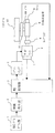
本発明の実施の形態に係る位置検出装置について、図面を参照しながら説明する。本発明の実施の形態に係る位置検出装置は、図3に示した従来のものと同様の構成からなるが、軸制御部3内部の構成、及び動作が従来のものと異なる。すなわち、本実施の形態の軸制御部3は、図1に示すように、位置ループ演算部31と、速度ループ演算部32と、出力部33と、第1入力部34と、第2入力部35と、微分演算部36と、位置合成部37と、位置修正部38と、第1〜第4の差分器41〜44とから構成されている。図1は、本発明のフルローズド・ループの位置制御装置の軸制御部の一例を示す構成ブロック図である。ここで、従来と同様の構成をとるものには同一の符号を付し、その説明を省略する。図2は、図1のブロック図の動作を表す説明図である。
【0011】
位置修正部38は、位置合成部37が出力する合成後の位置情報に対し、サーボモータ5側の位置検出器7(本発明の第1位置検出器)が出力する位置情報の微分結果と、合成後の位置情報の差分との比較に基づいた修正を行い、修正後の位置情報P4を出力する。第3の差分器43は、位置合成部37が出力する位置情報P3から、位置修正部38が前回出力した修正後の位置情報P4(n−1)を差引きして、次の(6)式のように直接位置検出器11(本発明の第2位置検出器)側の速度情報V2(本発明の第2速度情報)を演算する。この第3の差分器43が、本発明の第2微分演算部に相当する。
【0012】
【数2】
V2=P3−P4(n-1) ・ ・ ・ (6)
【0013】
また、本発明の第1微分演算部にあたる微分演算部36がサーボモータ5側の位置検出器7からの位置情報を微分して求めた速度情報V1(本発明の第1速度情報)から速度情報V2が第4の差分器44により差引演算され、次の(7)式のように、速度情報の差の値V3として出力される。この第4の差分器44が本発明の差分器に相当する。
【0014】
【数3】
V3=V1−V2 ・ ・ ・ (7)
【0015】
位置修正部38は、次の(8)式の演算により、位置合成部37で求められた位置情報P3を修正して、修正後の位置情報P4(n)を求める。
【0016】
【数4】
P4(n)=P3+INT(V3+0.5) ・ ・ ・ (8)
【0017】
このように、本実施の形態によれば、サーボモータ5の位置検出器7側の位置情報から求められる速度V1と、直接位置検出器11側から求められる速度V2との差に基づき、位置合成部37が演算する位置情報P3の誤りを位置修正部38が修正するようにしているので、大きいバックラッシュに対しても位置検出精度を維持し、これにより長年に渡り高精度な位置決めが可能となる。
【0018】
次に、本実施形態の位置検出装置の動作について具体的な数値例を示して説明する。図2は、位置検出器7から見た直接位置検出器11のバックラッシュが±0.6゜あり、n=1の時点以降に、軸制御部3のサンプル時間当りに0.3゜だけ、サーボモータ5が回転する場合の(1)から(8)式の計算結果である。
【0019】
n=3の時点では、バックラッシュが従来のシステムの許容値±0.5゜を超えているので、位置合成部37の検出位置P3は誤った計算結果となっている。ここで、サーボモータ5の回転速度を大きく超えて円テーブル12が動くことはないと考えると、両者の速度の差が基準値(−0.5から+0.5)の範囲外であるのは、位置の合成を誤ったからであると判断できる。そこで、両者の速度の差V3を、(8)式のように評価することで、位置の修正が可能となる。
【0020】
【発明の効果】
本発明によれば、モータ側の検出器から求められる速度と直接位置検出器側から求められる速度の差に基づき、位置合成部により合成された位置情報の誤りを位置修正部が修正する位置検出装置としているので、経時劣化等によってバックラッシュが大きくなっても、高い位置検出精度を維持でき、これにより、長年に渡り高精度な位置決めを可能とする。
【図面の簡単な説明】
【図1】 本発明の実施の形態に係るフルローズド・ループの位置制御装置の軸制御部の一例を示す構成ブロック図である。
【図2】 本発明の実施の形態に係る位置制御装置の動作を表す説明図である。
【図3】 従来のフルローズド・ループの位置制御装置の一例を示す構成ブロック図である。
【図4】 従来のフルローズド・ループの位置制御装置の軸制御部の一例を示す構成ブロック図である。
【符号の説明】
1 NCプログラム部、2 関数発生部、3 軸制御部、4 パワーアンプ、5 サーボモータ、6 カップリング、7 位置検出器、8 ウオーム、9 円板状歯車、10 ジク、11 直接位置検出器、12 円テーブル、31 位置ループ演算、32 速度ループ演算、33 出力部、34 入力部、35 入力部、36 微分演算部、37 位置合成部、38 位置修正部、41,42,43,44 差分器。[0001]
BACKGROUND OF THE INVENTION
The present invention relates to a position control device for controlling the position of a feed shaft of a machine tool or the like, and more particularly to a position control device for a fully closed loop for a shaft having a large backlash amount using a gear reduction mechanism or the like.
[0002]
[Prior art]
A conventional position control device will be described with reference to FIG. In the conventional position control device, based on the
[0003]
Conventionally, the
[0004]
[Expression 1]
X = INT (P1 + 0.5) (1)
However, INT () is a function that returns the largest integer that does not exceed the numerical value in parentheses. (Example: INT (1.9) = 1, INT (-1.9) =-2)
Y = P1 + 0.5−X (2)
Z = Y-P2 (3)
If Z ≧ 0, P3 = X + P2 (4)
If Z <0, P3 = X + P2-1 (5)
[0005]
That is, according to this, the integer part of the position detection value P1 obtained by the
[0006]
[Problems to be solved by the invention]
Therefore, in the conventional position control device, when the amount of backlash increases due to wear of gears or the like, there is a problem that the backlash exceeds the allowable amount of backlash and is positioned at an incorrect position.
[0007]
The present invention has been made in view of the above circumstances, and a fully-closed loop position detection device capable of maintaining high positioning accuracy and performing stable position control over many years even when the backlash amount is large. The purpose is to provide.
[0008]
[Means for Solving the Problems]
The present invention for solving the problems of the conventional example includes a first position detector that detects a rotational position of a motor, a second position detector that directly detects a position of a driving target of the motor, and the first position detector. a position synthesizing section positioned adds the fractional part of the position information detected by the second position detector and the detected integer part of the position information by the detector synthesis, a position controller Ru wherein the By differentiating the position information output by the first position detector, the first differential calculation unit for calculating the first speed information and the second speed by differentiating the position information output by the position synthesis unit. a second differentiating unit for calculating the information, said the first velocity information and differentiator for obtaining the subtraction speed difference and said second velocity information outputted from the pre-Symbol position combining unit synthetic position information and year speed difference Add the integer part of It viewed including the position information correcting unit for outputting location information, and has a combination position information after the modification is characterized in that a feedback loop for controlling the motor.
[0009]
As a result, the change in the position information after the combination is compared with the change in the rotational position information of the motor, and the position information after the combination is corrected based on the change. Using this corrected position information, the backlash amount is reduced. Even when it is large, high positioning accuracy can be maintained.
[0010]
DETAILED DESCRIPTION OF THE INVENTION
A position detection apparatus according to an embodiment of the present invention will be described with reference to the drawings. The position detection device according to the embodiment of the present invention has the same configuration as the conventional one shown in FIG. 3, but the internal configuration and operation of the
[0011]
The
[0012]
[Expression 2]
V2 = P3-P4 (n-1) (6)
[0013]
Further, the speed information from speed information V1 (first speed information of the present invention) obtained by differentiating the position information from the
[0014]
[Equation 3]
V3 = V1-V2 (7)
[0015]
The
[0016]
[Expression 4]
P4 (n) = P3 + INT (V3 + 0.5) (8)
[0017]
Thus, according to the present embodiment, position synthesis is performed based on the difference between the speed V1 obtained from the position information on the
[0018]
Next, the operation of the position detection apparatus of the present embodiment will be described with specific numerical examples. FIG. 2 shows that the backlash of the
[0019]
Since the backlash exceeds the allowable value ± 0.5 ° of the conventional system at the time point of n = 3, the detection position P3 of the
[0020]
【The invention's effect】
According to the present invention, based on the difference between the speed obtained from the detector on the motor side and the speed obtained from the direct position detector side, the position correction unit corrects the position information error synthesized by the position synthesis unit. Since the apparatus is used, high position detection accuracy can be maintained even when backlash increases due to deterioration over time, and thereby high-precision positioning is possible for many years.
[Brief description of the drawings]
FIG. 1 is a block diagram showing an example of a shaft control unit of a position control device for a full rose loop according to an embodiment of the present invention.
FIG. 2 is an explanatory diagram showing the operation of the position control device according to the embodiment of the present invention.
FIG. 3 is a block diagram showing an example of a conventional full rose loop position control device.
FIG. 4 is a block diagram showing an example of an axis control unit of a conventional full rose loop position control device.
[Explanation of symbols]
1 NC program section, 2 function generation section, 3 axis control section, 4 power amplifier, 5 servo motor, 6 coupling, 7 position detector, 8 worm, 9 disc gear, 10 jig, 11 direct position detector, 12 circular table, 31 position loop calculation, 32 speed loop calculation, 33 output unit, 34 input unit, 35 input unit, 36 differential calculation unit, 37 position synthesis unit, 38 position correction unit, 41, 42, 43, 44 differentiator .
Claims (1)
前記モータの駆動対象の位置を直接検出する第2位置検出器と、
前記第1位置検出器により検出された位置情報P1の整数部分と前記第2位置検出器により検出された位置情報P2の小数部分とを加算し合成位置情報P3を出力する位置合成部と、
前記第1位置検出器が出力する位置情報P1を微分することにより、第1速度情報を演算する第1微分演算部と、
前記位置合成部が出力する合成位置情報P3を微分することにより、第2速度情報を演算する第2微分演算部と、
前記第1速度情報と前記第2速度情報とを減算し速度差を求める差分器と、
前記位置合成部により出力された合成位置情報P3と前記速度差の整数部分とを加算し修正後合成位置情報P4を出力する位置情報修正部と、
を含み、
前記修正後合成位置情報P4を前記モータを制御する制御ループにフィードバックすることを特徴とするフルクローズド・ループの位置制御装置。A first position detector for detecting the rotational position of the motor;
A second position detector for directly detecting the position of the motor drive target;
A position synthesizing unit for outputting the sum of the fractional part combination position information P3 of the position information P2 detected by the integer portion and the second position detector of the position information P1 detected by the first position detector,
By pre-Symbol first position detector differentiates the position information P1 for outputting a first differentiating unit for calculating a first speed information,
A second differential calculation unit that calculates second speed information by differentiating the combined position information P3 output by the position combining unit;
A subtractor for subtracting the first speed information and the second speed information to obtain a speed difference;
A position information correcting unit that adds the combined position information P3 output by the position combining unit and the integer part of the speed difference and outputs corrected combined position information P4 ;
Only including,
A position control device for a fully closed loop, wherein the corrected combined position information P4 is fed back to a control loop for controlling the motor .
Priority Applications (1)
| Application Number | Priority Date | Filing Date | Title |
|---|---|---|---|
| JP2000353807A JP3768092B2 (en) | 2000-11-21 | 2000-11-21 | Fully closed loop position controller |
Applications Claiming Priority (1)
| Application Number | Priority Date | Filing Date | Title |
|---|---|---|---|
| JP2000353807A JP3768092B2 (en) | 2000-11-21 | 2000-11-21 | Fully closed loop position controller |
Publications (2)
| Publication Number | Publication Date |
|---|---|
| JP2002157018A JP2002157018A (en) | 2002-05-31 |
| JP3768092B2 true JP3768092B2 (en) | 2006-04-19 |
Family
ID=18826508
Family Applications (1)
| Application Number | Title | Priority Date | Filing Date |
|---|---|---|---|
| JP2000353807A Expired - Fee Related JP3768092B2 (en) | 2000-11-21 | 2000-11-21 | Fully closed loop position controller |
Country Status (1)
| Country | Link |
|---|---|
| JP (1) | JP3768092B2 (en) |
Families Citing this family (2)
| Publication number | Priority date | Publication date | Assignee | Title |
|---|---|---|---|---|
| JP4782766B2 (en) | 2007-12-27 | 2011-09-28 | オークマ株式会社 | Machine diagnostic method and apparatus |
| JP5956857B2 (en) * | 2012-07-06 | 2016-07-27 | オークマ株式会社 | Control device with position correction function |
-
2000
- 2000-11-21 JP JP2000353807A patent/JP3768092B2/en not_active Expired - Fee Related
Also Published As
| Publication number | Publication date |
|---|---|
| JP2002157018A (en) | 2002-05-31 |
Similar Documents
| Publication | Publication Date | Title |
|---|---|---|
| US6590358B1 (en) | Servocontrol device | |
| US5760562A (en) | Apparatus and method for generating digital position signals for a rotatable shaft | |
| JP3129622B2 (en) | Quadrant projection correction method in full closed loop system | |
| WO2000019288A1 (en) | Position controller | |
| JP2000250614A (en) | Backlash correction device and numerical control system | |
| WO1988008640A1 (en) | Device for controlling speed of servo motor | |
| JP4014719B2 (en) | NC machine tool control apparatus and positioning control method | |
| JP4361285B2 (en) | Numerical controller | |
| JP5469053B2 (en) | Position speed controller | |
| JPS6294251A (en) | Device for controlling position | |
| JP3768092B2 (en) | Fully closed loop position controller | |
| JPH0835857A (en) | Method for detecting angle of rotation | |
| JP5956857B2 (en) | Control device with position correction function | |
| JPH0884492A (en) | Method and apparatus for operating servo motor synchronously | |
| JP6333495B1 (en) | Servo control device | |
| JP3551762B2 (en) | Motor control device | |
| JP7319178B2 (en) | Servo motor controller | |
| CN100433535C (en) | DC electric machine position control method | |
| JP2660006B2 (en) | Rotor angle detection method | |
| JPS6172312A (en) | Positioning system | |
| JPH0588751A (en) | Positioning device | |
| JPH0425908A (en) | Detection of position for industrial robot | |
| JPH08317679A (en) | Motor speed control system | |
| JP2547395B2 (en) | Absolute position detection method | |
| JP2003345402A (en) | Position control device |
Legal Events
| Date | Code | Title | Description |
|---|---|---|---|
| A621 | Written request for application examination |
Free format text: JAPANESE INTERMEDIATE CODE: A621 Effective date: 20031209 |
|
| A977 | Report on retrieval |
Free format text: JAPANESE INTERMEDIATE CODE: A971007 Effective date: 20051012 |
|
| A131 | Notification of reasons for refusal |
Free format text: JAPANESE INTERMEDIATE CODE: A131 Effective date: 20051018 |
|
| A521 | Written amendment |
Free format text: JAPANESE INTERMEDIATE CODE: A523 Effective date: 20051216 |
|
| RD04 | Notification of resignation of power of attorney |
Free format text: JAPANESE INTERMEDIATE CODE: A7424 Effective date: 20051216 |
|
| TRDD | Decision of grant or rejection written | ||
| A01 | Written decision to grant a patent or to grant a registration (utility model) |
Free format text: JAPANESE INTERMEDIATE CODE: A01 Effective date: 20060124 |
|
| A61 | First payment of annual fees (during grant procedure) |
Free format text: JAPANESE INTERMEDIATE CODE: A61 Effective date: 20060131 |
|
| R150 | Certificate of patent or registration of utility model |
Free format text: JAPANESE INTERMEDIATE CODE: R150 |
|
| FPAY | Renewal fee payment (event date is renewal date of database) |
Free format text: PAYMENT UNTIL: 20120210 Year of fee payment: 6 |
|
| FPAY | Renewal fee payment (event date is renewal date of database) |
Free format text: PAYMENT UNTIL: 20120210 Year of fee payment: 6 |
|
| FPAY | Renewal fee payment (event date is renewal date of database) |
Free format text: PAYMENT UNTIL: 20150210 Year of fee payment: 9 |
|
| LAPS | Cancellation because of no payment of annual fees |