JP3763682B2 - Speaker device - Google Patents
Speaker device Download PDFInfo
- Publication number
- JP3763682B2 JP3763682B2 JP29265498A JP29265498A JP3763682B2 JP 3763682 B2 JP3763682 B2 JP 3763682B2 JP 29265498 A JP29265498 A JP 29265498A JP 29265498 A JP29265498 A JP 29265498A JP 3763682 B2 JP3763682 B2 JP 3763682B2
- Authority
- JP
- Japan
- Prior art keywords
- cabinet
- acoustic
- standing wave
- acoustic tube
- tube
- Prior art date
- Legal status (The legal status is an assumption and is not a legal conclusion. Google has not performed a legal analysis and makes no representation as to the accuracy of the status listed.)
- Expired - Fee Related
Links
- 239000011358 absorbing material Substances 0.000 claims description 54
- 239000012779 reinforcing material Substances 0.000 claims description 3
- 238000010586 diagram Methods 0.000 description 23
- 239000002245 particle Substances 0.000 description 16
- 238000005192 partition Methods 0.000 description 7
- 239000000463 material Substances 0.000 description 6
- 238000010521 absorption reaction Methods 0.000 description 4
- 230000000694 effects Effects 0.000 description 3
- 230000002238 attenuated effect Effects 0.000 description 2
- 230000007423 decrease Effects 0.000 description 2
- 238000005259 measurement Methods 0.000 description 2
- 230000005236 sound signal Effects 0.000 description 2
- 230000001629 suppression Effects 0.000 description 2
- 239000011491 glass wool Substances 0.000 description 1
- 230000002452 interceptive effect Effects 0.000 description 1
- 238000004519 manufacturing process Methods 0.000 description 1
- 238000000638 solvent extraction Methods 0.000 description 1
Images


Classifications
-
- H—ELECTRICITY
- H04—ELECTRIC COMMUNICATION TECHNIQUE
- H04R—LOUDSPEAKERS, MICROPHONES, GRAMOPHONE PICK-UPS OR LIKE ACOUSTIC ELECTROMECHANICAL TRANSDUCERS; DEAF-AID SETS; PUBLIC ADDRESS SYSTEMS
- H04R1/00—Details of transducers, loudspeakers or microphones
- H04R1/20—Arrangements for obtaining desired frequency or directional characteristics
- H04R1/22—Arrangements for obtaining desired frequency or directional characteristics for obtaining desired frequency characteristic only
- H04R1/28—Transducer mountings or enclosures modified by provision of mechanical or acoustic impedances, e.g. resonator, damping means
- H04R1/2869—Reduction of undesired resonances, i.e. standing waves within enclosure, or of undesired vibrations, i.e. of the enclosure itself
- H04R1/2884—Reduction of undesired resonances, i.e. standing waves within enclosure, or of undesired vibrations, i.e. of the enclosure itself by means of the enclosure structure, i.e. strengthening or shape of the enclosure
- H04R1/2888—Reduction of undesired resonances, i.e. standing waves within enclosure, or of undesired vibrations, i.e. of the enclosure itself by means of the enclosure structure, i.e. strengthening or shape of the enclosure for loudspeaker transducers
-
- H—ELECTRICITY
- H04—ELECTRIC COMMUNICATION TECHNIQUE
- H04R—LOUDSPEAKERS, MICROPHONES, GRAMOPHONE PICK-UPS OR LIKE ACOUSTIC ELECTROMECHANICAL TRANSDUCERS; DEAF-AID SETS; PUBLIC ADDRESS SYSTEMS
- H04R1/00—Details of transducers, loudspeakers or microphones
- H04R1/20—Arrangements for obtaining desired frequency or directional characteristics
- H04R1/22—Arrangements for obtaining desired frequency or directional characteristics for obtaining desired frequency characteristic only
- H04R1/28—Transducer mountings or enclosures modified by provision of mechanical or acoustic impedances, e.g. resonator, damping means
- H04R1/2869—Reduction of undesired resonances, i.e. standing waves within enclosure, or of undesired vibrations, i.e. of the enclosure itself
- H04R1/2876—Reduction of undesired resonances, i.e. standing waves within enclosure, or of undesired vibrations, i.e. of the enclosure itself by means of damping material, e.g. as cladding
- H04R1/288—Reduction of undesired resonances, i.e. standing waves within enclosure, or of undesired vibrations, i.e. of the enclosure itself by means of damping material, e.g. as cladding for loudspeaker transducers
Landscapes
- Health & Medical Sciences (AREA)
- Otolaryngology (AREA)
- Physics & Mathematics (AREA)
- Engineering & Computer Science (AREA)
- Acoustics & Sound (AREA)
- Signal Processing (AREA)
- Obtaining Desirable Characteristics In Audible-Bandwidth Transducers (AREA)
Description
【0001】
【発明の属する技術分野】
本発明は、スピーカ装置のキャビネット内における定在波を抑制することを可能とするスピーカ装置に関する。
【0002】
【従来の技術】
周知のごとく、スピーカユニットは音声情報を担う電気信号(以下、音声信号という)に応じて振動板を振動させることによって音波を空気中に放射する音響変換器であり、単独で用いられることはほとんどなく、通常は良好な音響再生を行う目的でバッフル板に取り付けられてスピーカ装置として用いられる。
【0003】
本来、スピーカユニットが取り付けられるバッフル板が無限の大きさであれば振動板の前後から放射される音波の干渉を完全に防ぐことができるが、実際は有限の大きさを有するバッフル板にスピーカユニットが取り付けられる。
【0004】
スピーカ装置に用いられるキャビネットは、これを具現化したものであり、一般には有限の大きさのバッフル板を1つの壁面に用いて密閉または一部が開放した音響箱によって構成される。
【0005】
図12は従来のスピーカ装置の一例を示した図であり、ここでは直方体形状の密閉型キャビネット箱に1個のスピーカユニットが取り付けられたスピーカ装置Sを示している。
【0006】
同図に示すようにスピーカ装置Sは、密閉型のキャビネット101の一面に形成された有限の大きさのバッフル板101aにスピーカユニット102が取り付けられており、図示せぬ入力端子から供給される音声信号によってスピーカユニット102の振動板が前後に駆動されることにより振動板の表面側(外部空間側)より該音声信号に応じた音波が外部に放射されて音響再生がなされる。
【0007】
ここで、キャビネット101の内部空間は直方体の有限空間であるので、振動板の裏面(内部空間側)からキャビネットの内部空間に放射される音波がバッフル板101aに対向する裏板101b、あるいは、天板101cに対向する地板101dで互いに反射して、対向する壁面位置が節となる定在波を生じる。
【0008】
この時、壁面間に生じる定在波には、該壁面間の間隔のおよそ2倍に相当する波長の定在波(最低共振モード)のほか、最低共振モードのn倍(nは自然数)の共振周波数に相当する高次モードが含まれる。
【0009】
図12中、(a)ではキャビネット101内の天板101Cと地板101dの間とバッフル板101a及び裏板101b間にそれぞれ生じる定在波のうちの最低共振モード103、104を示し、(b)ではそれぞれ生じる上記定在波のうちの最低共振モードの2倍の共振周波数、即ち、最低共振モードの1/2の波長を有する高次モード103a、104aを示している。
【0010】
これらキャビネット101内に生じる定在波は、スピーカユニット102の振動板の動きを阻害する作用を担うので、スピーカ装置Sの再生音質を劣化させる大きな要因となる。
【0011】
そのため、従来では、キャビネット内に生じる定在波を極力緩和させるために図13に示すスピーカ装置の各例に見られるようなさまざまな工夫がなされていた。
【0012】
即ち、図13(a)に示すようにキャビネット101の内壁面にグラスウールなどの吸音材105を取り付けて定在波の音圧を減衰させたり、図13(b)に示すようにキャビネット101の内側に特定の周波数に共鳴するヘルムホルツ共鳴器106を取り付けたり、図13(c)に示すように直方体のキャビネット101の代りに平行な壁面をなくした異型のキャビネット107を用いてキャビネット内の定在波を極力抑えていた。
【0013】
しかしながら、上記吸音材105をキャビネット101の内壁面に取り付けてキャビネット101により生じた定在波の音圧を十分減衰させるためには、吸音材105を相当量用いる必要があり、その結果音響抵抗が増えるので、低音域が吸収されてしまう。
【0014】
また、ヘルムホルツ共鳴器106は共鳴する単一の周波数に対し吸音効果があるのでたとえばキャビネット内に発生する特定の波長の定在波に対しては作用するが、その他の波長の定在波に対しては効果的に作用しない。
【0015】
また、異型のキャビネット107は、構造が複雑となりコスト高となるほかスピーカ装置のデザイン上の制約が大きくなる。
【0016】
【発明が解決しようとする課題】
本発明は、上述の問題点に鑑みなされたものであり、簡単な構造でキャビネット内における定在波を十分抑制することのできるスピーカ装置を提供することを目的とする。
【0017】
【課題を解決するための手段】
請求項1に記載の発明は、スピーカユニットと、当該スピーカユニットを取り付けるバッフル板を含む複数の壁面により前記スピーカユニットの後面側に内部空間を形成するキャビネットと、中空断面を有して前記内部空間において少なくとも一の前記壁面に沿って形成され、一方の端部に開口部を有し、かつ他方の端が閉塞された音響管と、当該音響管の前記開口部を塞いで前記内部空間と前記音響管の内部空間とを隔離する吸音材と、を備え、前記音響管は、前記内部空間において発生する定在波のうち、前記一の壁面に沿って発生する定在波の最低共振モードに対応する波長の略1/(4n)倍(nは1以上の自然数)の管長を有し、前記開口部は前記定在波の節の近傍に位置するように配置されてなることを特徴とする。
【0018】
また、請求項2記載の発明は、請求項1に記載のスピーカ装置において、音響管が有する壁面が内部空間に形成された音道が有する壁面の少なくとも一部を構成することを特徴とする。
【0019】
また、請求項3記載の発明は、請求項1に記載のスピーカ装置において、音響管は、少なくとも一部がキャビネットの構造を補強する補強材を構成することを特徴とする。
【0020】
【作用】
本発明によれば、スピーカユニットの駆動動作によりキャビネットの内部空間に定在波が生じても、音響管がこれを打ち消すように管共振することによって該音響管に取り付けた吸音材と共に減衰させて吸収するので、定在波が十分抑制される。
【0021】
【発明の実施の形態】
次に、本発明の好適な実施の形態について図をもとに説明する。
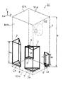
図1は、本発明の一実施形態におけるスピーカ装置S1のキャビネットの内部構造を示した図である。ここではキャビネット1は、その内部空間が直方体となる密閉型キャビネットである。
【0022】
キャビネット1は、スピーカユニット102が取り付けられたバッフル板101aを含む各壁面(図1では1つのバッフル板101aを含む6つの壁面)によってスピーカユニット102の後面側に密閉空間を形成し、スピーカユニット102の外部空間と内部空間とを音響的に隔離する。つまりこの密閉空間を形成することにより、バッフル板101aに取り付けられたスピーカユニット102の振動板の前後から放射される音波が干渉するのを防ぐことができる。なお、この密閉空間は、スピーカ装置S1としての必要な音響特性を得るためにスピーカユニット102の諸特性に合わせて調整された所定の容積を有する。
【0023】
また、図1に示すように、キャビネット1内の壁面には音響管2、3、4、5が設けられている。各音響管は、一方端が閉塞されると共に他方端が開放された三角柱状の中空管であって、従って、各音響管の水平方向(図中のX−Y平面と平行な方向)の断面は、ほぼ一様な中空の断面(この場合は三角形状)となる。各音響管の各開口部2a、3a、4a、5aにそれぞれ吸音材6、7、8、9が取り付けられている。
【0024】
音響管2、3、4、5及び吸音材6、7、8、9は、スピーカユニット102の駆動動作によりキャビネット1に生じる定在波を抑制するために設けられたものであり、ここでは、キャビネット1の互いに平行な天板101cと地板101dの2つの壁面によって密閉空間の上下方向(図中Z方向)に生じる定在波を抑制するために、各音響管の開口部が地板101dと向き合うように配置される。
【0025】
音響管2及び音響管3は同形状であり、それぞれの管長(ここでは、各音響管の閉塞された一方端から開口された他方端までの長さをいう。)は、キャビネット1の天板101cと地板101dの各壁面の間隔Hの約1/2の長さhaである。音響管2及び音響管3の開口部2a、3aは、それぞれキャビネット1の地板101dと若干の隙間を介して対向するように配されている。また、開口部2a、3aには、それぞれ吸音材6、7が開口部2a、3aを塞ぐように取り付けられている。
【0026】
また、音響管4及び音響管5は同形状であり、それぞれの管長は、キャビネット1の天板101cと地板101dの各壁面の間隔Hの約1/4の長さhbで形成され、音響管4、5の開口部4a、5aは、それぞれキャビネット1の地板101dと若干の隙間を介して対向するように配されている。また、開口部4a、5aには、それぞれ吸音材8、9が開口部4a、5aを塞ぐように取り付けられている。
【0027】
キャビネット1内の各音響管2、3、4、5及び各吸音材6、7、8、9は以上のようにキャビネット1内に取り付けられて固定され、スピーカユニット102が駆動動作した場合にキャビネット1内に生じる定在波を各音響管2、3、4、5による管共振によって生じる共振波によって抑制する。
【0028】
次に、上記各音響管及び吸音材がキャビネット1内に生じる定在波を抑制する動作について以下に説明する。
【0029】
図2は、図1におけるスピーカ装置S1のキャビネット1に取り付けられたスピーカユニット102の駆動中にキャビネット1内の上下方向(図中Z方向)に生じる定在波と音響管2及び吸音材6によって生じる共振波を模式的に表した図である。
【0030】
キャビネット1内のZ方向には、天板101c及び地板101dの内壁面を節とし、Z方向の間隔Hをλ/2(λ:波長)とする最低共振モード及びその高次モードが定在波として生じる。また、吸音材6が取り付けられた音響管2の開口部2aはキャビネット1内のZ方向に生じる定在波の節の近傍(図2では、キャビネット1の地板101d近傍)に配されている。したがって、吸音材6が取り付けられた音響管2は、スピーカユニット102の駆動動作によって管共振し、その管長に対応する共振波を生じる。
【0031】
この共振波は、音響管2の閉塞された一方端が節となり、開口部2a付近が腹となるように生じる共振波である。
【0032】
図2(a)は、間隔Hがλ/2となる定在波110(つまり、Z方向に生じる定在波のうちの最低共振モード)が生じる場合を示し、図2(b)は、間隔Hが、3λ/2となる定在波111(つまり、Z方向に生じる定在波のうちの最低共振モードの3倍の共振周波数を有する高次モード)が生じる場合を示している。
【0033】
図2(a)において、スピーカユニット102の駆動動作によりキャビネット1内に定在波110が生じるが、この場合に音響管2は管長haが定在波110の約1/4波長分の長さを有するので、管共振により定在波110の約1/4波長分の共振波112が生じる。
【0034】
定在波110及び共振波112は、それぞれ節に相当する位置に近いほど音響インピーダンスが高くなるので粒子速度(空気の流れ)が小さく分布し、腹に相当する位置に近いほど音響インピーダンスが低くなるので粒子速度が大きく分布する。したがって、図2(a)に示すように共振波112の節が定在波110の腹の近傍に配され、共振波112の腹が定在波110の節の近傍に配される。つまり、定在波110にそれとは逆の粒子速度分布を有する共振波112が付加されると、共振波112は定在波110によって生じるキャビネット1内の粒子速度の分布差を緩和することになり、吸音材6が取り付けられた音響管2が定在波110の振幅を抑制することになる。
【0035】
また、図2(b)に示すように、キャビネット1内に定在波111が生じる場合に音響管2は管長haが定在波111の約3/4波長分の長さを有するので、管共振により定在波111の約3/4波長分の共振波113が生じる。
【0036】
共振波113は上述した図2(a)の定在波110に対する共振波112と同様に、共振波113の節が定在波111の腹の近傍に配され、共振波113の腹が定在波111の節の近傍に配される。つまり、定在波111にそれとは逆の粒子速度分布を有する共振波113が付加されると、共振波113は定在波111によって生じるキャビネット1内の粒子速度の分布差を緩和することになり、吸音材6が取り付けられた音響管2が定在波111の振幅を抑制することになる。
【0037】
このように、キャビネット1内に固定された音響管2は、キャビネット1のZ方向に生じる定在波のうちの最低共振モードの波長の1/4の管長haを有し、閉塞された一方端が節となり、開口部2aが腹となる共振波を生じるので、定在波110、111を含め最低共振モードの2n−1倍(nは自然数)の共振周波数を有する高次モードに対しても同様に抑制することができる。
【0038】
なお、スピーカユニット102からみてキャビネット1と音響管2は開口部2aによって連結される2つの音響管の結合体とみなすことができるが、吸音材6によって音響管2の内部空間とキャビネット1の内部空間とは音響空間的には隔離されることとなり、これら2つの音響管の結合体の共振に基づく上記共振波10乃至13以外の新たな定在波がキャビネット1内に発生するのを抑制することができる。
【0039】
また上記説明では、吸音材6及び音響管2によるキャビネット1内のZ方向に生じる定在波を抑制する動作を説明したが、吸音材7及び音響管3による場合も同様であり、説明が重複するので省略する。
【0040】
次に、図3は、図1におけるスピーカ装置S1のキャビネット1に取り付けられたスピーカユニット102の駆動中にキャビネット1内の上下方向(図中Z方向)に生じる定在波と音響管4及び吸音材8によって生じる共振波を模式的に表した図である。
【0041】
図3(a)は、間隔Hがλとなる定在波114(つまり、Z方向に生じる定在波のうち最低共振モードの2倍の共振周波数を有する高次モード)が生じる場合を示し、図3(b)は、間隔Hが3λとなる定在波115(つまり、最低共振モードの6倍の共振周波数を有する高次モード)が生じる場合を示している。
【0042】
図3(a)において、スピーカユニット102の駆動動作によりキャビネット1内に定在波114が生じるが、この場合に音響管4は管長hbが定在波114の約1/4波長(最低共振モードの波長の1/8)の長さを有するので、管共振により定在波114の約1/4波長分の共振波116が生じる。
【0043】
定在波114及び共振波116は、それぞれ節に相当する位置に近いほど音響インピーダンスが高くなるので粒子速度(空気の流れ)が小さく分布し、腹に相当する位置に近いほど音響インピーダンスが低くなるので粒子速度が大きく分布する。したがって、図3(a)に示すように共振波116の節が定在波114の腹の近傍に配され、共振波116の腹が定在波114の節の近傍に配される。つまり、定在波114にそれとは逆の粒子速度分布を有する共振波116が付加されると、共振波116は定在波114によって生じるキャビネット1内の粒子速度の分布差を緩和することになり、吸音材8が取り付けられた音響管4が定在波114の振幅を抑制することになる。
【0044】
また、図3(b)に示すように、キャビネット1内に定在波115が生じる場合に音響管4は管長hbが定在波115の約3/4波長分の長さを有するので、管共振により定在波115の約3/4波長分の共振波117が生じる。
【0045】
共振波117は上述した図3(a)の定在波114に対する共振波116と同様に、共振波117の節が定在波115の腹の近傍に配され、共振波117の腹が定在波115の節の近傍に配される。つまり、定在波115にそれとは逆の粒子速度分布を有する共振波117が付加されると、共振波117は定在波115によって生じるキャビネット1内の粒子速度の分布差を緩和することになり、吸音材8が取り付けられた音響管4が定在波115の振幅を抑制することになる。
【0046】
このように、キャビネット1内に固定された音響管4は、キャビネット1のZ方向に生じる定在波のうちの最低共振モードの波長の1/8の管長hbを有し、閉塞された一方端が節となり、開口部4aが腹となる共振波を生じるので、定在波114、15を含め最低共振モードの2(2n−1)倍(nは自然数)の周波数の高次モードによる定在波に対しても同様に抑制することができる。
【0047】
なお、図3では、吸音材9及び音響管5による抑制動作も吸音材8、音響管4による抑制動作と同様であり、説明が重複するので省略する。
【0048】
以上説明した通り、キャビネット1内の各音響管2、3、4、5及び各吸音材6、7、8、9によってキャビネット1内のZ方向に生じる定在波を抑制することができる。
【0049】
図4は、スピーカ装置S1の実測によって得られた再生音圧周波数特性を示す図であり、図中Qはスピーカ装置S1の再生音圧周波数特性であり、Pはスピーカ装置S1の各音響管2、3、4、5及び各吸音材6、7、8、9を取り除いた場合に得られる再生音圧周波数特性を示している。図中、縦軸は音圧(dB)で示され、横軸は周波数(Hz)で示される。
【0050】
図4からわかるように、キャビネット1内に各音響管2、3、4、5及び各吸音材6、7、8、9を設けることによって、キャビネット1のZ方向に生じる定在波(最低共振モード(図中p1に相当)及びその高次モード(図中p2、p3に相当))が十分抑制されていることがわかる。
【0051】
なお、上述したスピーカ装置S1では、キャビネット1内のZ方向に沿って、Z方向の間隔Hの約1/2及び1/4の管長を有する2種類の音響管を対応する吸音材とともに、各2個づつキャビネット1に固定するように構成した例について説明したが、これに限らず、音響管の管長は、キャビネット内に生じる定在波のうち最低共振モードの波長の略1/(4n)(nは1以上の自然数)であれば良く、このような管長を有する1または複数種類の音響管を、各開口部を抑制する定在波に対して当該定在波の節にあたる位置の近傍に音響管の開口部を配すると共に、各開口部を塞ぐように吸音材を取り付けてキャビネットに固定するように構成すれば、各音響管に生じる共振波に応じた定在波の振幅を抑制できる。
【0052】
またキャビネット内の定在波を抑制するために当該定在波に沿ってキャビネット内に固定される音響管は同じ管長を有する音響管が1または複数個であっても良い。
【0053】
次に、図5は、本発明のその他の実施形態におけるスピーカ装置S2を示す図である。スピーカ装置S2は、開口部4a、5aにそれぞれ吸音材8、9が開口部4a、5aを塞ぐように取り付けられた音響管4、5がキャビネット1内のZ方向に沿って各2個づつ(計4個)固定されてなる。このような構成においてもキャビネット1内のZ方向に生じる定在波は、これらの各音響管及び各吸音材によって抑制される。
【0054】
また、図6は本発明のその他の実施形態におけるスピーカ装置S3を示す図である。スピーカ装置S3は、両端が開放された2つの三角柱状の音響管10がZ方向に沿って固定されている。この音響管10はその中央部分が仕切り板10bによって仕切られており、図2に示す音響管2、3と同等の4つの音響管10aが形成され、さらに2つある開口部10cにそれぞれ吸音材11が開口部10cを塞ぐように取り付けられると共に、音響管10aの開口部10cは、それぞれキャビネット1内のZ方向に生じる定在波のうち最低共振モードの節の近傍に配されている。かかる構成おいてもスピーカ装置S3のキャビネット1内のZ方向に生じる定在波を抑制できる。
【0055】
また、本発明を用いれば、吸音材が開口部に取り付けられる音響管をスピーカ装置のキャビネット1内のZ方向のみならず奥行き方向(X方向)や左右方向(Y方向)などの複数の異なる方向に生じる定在波に対応して複数配置することにより各方向に生じる定在波をそれぞれ抑制することができる。このようなスピーカ装置の一例を図7に示す。
【0056】
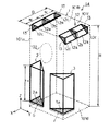
図7は本発明のその他の実施形態におけるスピーカ装置S4を示す図であり、スピーカ装置S4は、音響管2、3とそれらの開口部2a、3aに取り付けられる吸音材6、7が図1と同様にキャビネット1内のZ方向に沿って固定され、さらに各開口部12cに吸音材13が取り付けられる4つの音響管12aが、スピーカ装置S4のキャビネット1内のZ方向と直交するX方向(つまりキャビネット1のバッフル板101a及び裏板101bが相対する奥行き方向)に沿って固定される。
【0057】
4つの音響管12aは、ここでは、両端が開放された2つの三角柱状の中空管12の各中央部分をそれぞれ仕切り板12bで仕切ることにより、各管長がキャビネット1のバッフル板101aと裏板101bとの間隔Dの約1/2の長さhcとなるように形成される。各音響管12aの開口部12cには、それぞれ吸音材13が開口部12cを塞ぐように取り付けられる。吸音材13が取り付けられた音響管12aの管長hcは、キャビネット1のX方向に生じる定在波のうちの最低共振モードの波長の約1/4の長さに形成され、各開口部12cは、キャビネット1内のX方向に生じる定在波のうちの最低共振モードの節の近傍に位置するように若干の隙間を有して配される。
【0058】
これにより、スピーカ装置S3のキャビネット1内のZ方向に生じる定在波は、音響管2、3及び吸音材6、7によって抑制され、X方向に生じる定在波は、4つの音響管12a及び吸音材13によって抑制される.
【0059】
また、上述した各実施形態では、各音響管は、一方端が閉塞された閉塞部を有すると共に他方端が開放された開口部を有する三角柱状の中空管で形成し、キャビネット1内に固定するようにしたが、各音響管の中空断面形状はこれに限らず、円形その他の形状であっても良い。また、音響管に用いる材料は定在波を抑制することのできる共振波を生じる材料であれば適度な吸音率または反射率を有する材料で形成しても良い。
【0060】
図8は、円形の中空断面を有する紙管を用いて音響管を形成したその他の実施形態であるスピーカ装置S5を示した図である。
【0061】
スピーカ装置S5は、一方端が閉塞された閉塞部であると共に他方端が開放された開口部14a、15aを有する2つの中空管である紙管14、15がキャビネット1内のX方向に沿って固定されてなる。紙管14、15の各管長がキャビネット1のバッフル板101aと裏板101bとの間隔Dの約1/2の長さhcで形成される。
【0062】
また、開口部14a、15aには吸音材16、17が開口部14a、15aを塞ぐように取り付けられる。吸音材16、17が取り付けられた紙管14、15の管長hcは、キャビネット1のX方向に生じる定在波のうちの最低共振モードの波長の約1/4の長さに形成され、各開口部14a、15aは、キャビネット1内のX方向に生じる定在波のうちの最低共振モードの節の近傍に位置するように、バッフル板101aに対し若干の隙間を有して配される。
【0063】
また、スピーカ装置S5は一方端が閉塞された閉塞部であると共に他方端がそれぞれ開放された開口部18a、19aを有する2つの中空管である紙管18、19がキャビネット1内のZ方向に沿って固定されてなる。紙管18、19の各管長はキャビネット1の天板101c及び地板101dの内壁面の間隔Hの約1/2の長さhaで形成される。
【0064】
また、開口部18a、19aにはそれぞれ吸音材20、21が開口部18a、19aを塞ぐように取り付けられる。吸音材20、21が取り付けられた紙管18、19の管長haは、キャビネット1のZ方向に生じる定在波のうちの最低共振モードの波長の約1/4の長さに形成され、開口部18a、19aは、キャビネット1内のZ方向に生じる定在波のうちの最低共振モードの節の近傍に位置するようにキャビネット1の地板101dに対して若干の隙間を有して配される。
【0065】
これにより、スピーカ装置S5のキャビネット1内のX方向に生じる定在波は、音響管14、15及び吸音材16、17によって抑制され、Z方向に生じる定在波は、音響管18、19及び吸音材20、21によって抑制される.
【0066】
なお、上述した各実施形態では音響管は筒状に形成されてキャビネットに固定されるようにしたが、本発明はこれに限らず、音響管の一部をキャビネットの壁面で形成しても良い。音響管の一部をキャビネットの壁面で形成した実施例を図9によって以下に説明する。
【0067】
図9は、本発明のその他の実施形態におけるスピーカ装置S6を示す図である。スピーカ装置S6は、キャビネット1のバッフル板101aを挟む両側壁面の間隔W(図中Y方向)に等しい幅を有する矩形板22がキャビネット1内にバッフル板101aに平行に固定されることによってキャビネット1内の空間が仕切られ、矩形板22及び、キャビネット1の裏板101b及び左右の側壁面によって中空管23が形成される。
【0068】
中空管23は、その中央部分を仕切り板23bによって仕切ることにより2つの音響管23aを形成する。つまり、各音響管23aは、その一方端が仕切り板23bによって閉塞され、他方端に開口部23cを有する中空管であり、管長が上記間隔Hの約1/2の長さhaで形成される。
【0069】
各音響管23aの開口部23cには、それぞれ吸音材24が開口部23cを塞ぐように取り付けられる。吸音材24が取り付けられた音響管23aの管長haは、キャビネット1内のZ方向に生じる定在波のうちの最低共振モードの波長の約1/4の長さに形成され、各開口部23cは、キャビネット1内のZ方向に生じる定在波のうちの最低共振モードの節の近傍に位置するようにキャビネット1の天板101cもしくは地板101dに対して若干の隙間を有して配される。
【0070】
これにより、スピーカ装置S6のキャビネット1内のZ方向に生じる定在波は、2つの音響管23a及び吸音材24によって抑制される。
【0071】
また、スピーカ装置S6では音響管23aの一部がキャビネット1の裏板101b及びかかる裏板101bが挟持される両側壁面の一部によって形成されるので、音響管の作成コストを抑えることができ、また、キャビネット1内の空間の有効利用が図れる。
【0072】
また、音響管23aを構成する矩形板22によってキャビネット1が補強されるので、矩形板22は、音響管23aの一部を構成すると共にキャビネット1の構造を補強する補強材を構成するので、スピーカユニット102の駆動動作によるキャビネット1の板振動を抑えることができる。
【0073】
なお、上述した各実施形態におけるスピーカ装置を、密閉型のキャビネット1を有するスピーカ装置によって説明したが、本発明におけるスピーカ装置はこれに限らず、例えばバスレフ型、バックロードホーン型、フロントロードホーン型などのスピーカ装置としても良い。
【0074】
図10は、本発明のその他の実施形態におけるバスレフ型のスピーカ装置S7を示す図である。
図10において、スピーカ装置S7が有するキャビネット25は、バッフル板101aに開口部25bを有する音響ポート25aがキャビネット25の内部空間に形成されていて、スピーカユニット102が駆動動作する場合に、キャビネット25内に面するスピーカユニット102の振動板の裏面側からの放射音をこの音響ポート25aによって前面に導出させている。
【0075】
スピーカ装置S7は、両端が開放される三角柱状の中空管26の中央部分が仕切り板26bによって仕切られてキャビネット25内のZ方向に沿って裏板101bに固定されることにより2つの音響管26aを形成する。つまり、各音響管26aは、その一方端が仕切り板26bによって閉塞された閉塞部を有し、他方端に開口部26cを有する中空管であり、管長がキャビネット1の天板101cと地板101dの間隔Hの約1/2の長さhaとなるように形成されている。
【0076】
各音響管26aの開口部26cには、それぞれ吸音材27が開口部26cを塞ぐように取り付けられる。吸音材27が取り付けられた音響管26aの管長haは、キャビネット1内のZ方向に生じる定在波のうちの最低共振モードの波長の約1/4の長さに形成され、各開口部26cは、キャビネット1内のZ方向に生じる定在波のうちの最低共振モードの節の近傍に位置するようにキャビネット1の天板101cもしくは地板101dに対して若干の隙間を有するように配される。
【0077】
これにより、スピーカ装置S7のキャビネット1内のZ方向に生じる定在波は、2つの音響管26a及び吸音材27によって抑制される。
【0078】
図11は、スピーカ装置S7を上面(天板101c側)から見た図である。スピーカユニット102の振動板の内部空間側によって生じるキャビネット25の内部空間への放射音は、同図の矢印で示すように音響管26aの三角柱状の壁面と音響ポート25aによって形成される音道25cから音響ポート25a内を経て開口部25bから外部へ導出される。
【0079】
上述のように、音響管26aの三角柱状の外壁面がキャビネット25の内部空間に形成された音道25cが有する壁面の一部を構成するので、スピーカ装置S7のキャビネット25内のZ方向に生じる定在波は、音響管26a及び吸音材27によって抑制される。したがって、スピーカユニット102が駆動動作する場合に、音道25c及び音響ポート25aによって外部空間に放出されるスピーカユニット102からの放射音はキャビネット25内のZ方向に生じる定在波が十分抑制される。
【0080】
なお、上述した各実施形態におけるスピーカ装置では、1または複数の音響管を、抑制する定在波ごとに該定在波の生じる方向と一致させてキャビネットに固定し、さらに吸音材が取り付けられた開口部をキャビネットの内壁面に対向させて、且つ、該内壁面と若干の隙間を有する位置に配置させ、さらに、開口部を該定在波の節の近傍に配することにより、定在波による粒子速度の分布に対して音響管内の共振波による粒子速度の分布を逆に配置させて、キャビネット内の該定在波を抑制するようにしたが、本発明はこれに限らない。
【0081】
即ち、音響管は、定在波の粒子速度の分布と音響管内の共振波の粒子速度の分布とが逆方向の分布であれば良く、固定する方向は抑制する定在波の方向からずれていても同様に作用し実用に供することができる。
【0082】
また、開口部は必ずしもキャビネットの内壁面近傍に配される必要はなく、抑制する定在波(最低共振モードまたはその高次モード)の節の近傍に配されれば同様の効果を得ることができる。
【0083】
【発明の効果】
本発明によれば、スピーカユニットの駆動動作によりキャビネットの内部空間に定在波が生じても、該定在波の最低共振モードに対応する波長の略1/(4n)(nは1以上自然数)倍の管長を有し該内部空間の少なくとも一の壁面に沿って形成される音響管が、これを打ち消すように管共振することによって該音響管に取り付けた吸音材と共に減衰させて吸収するので、定在波が十分抑制される。
【図面の簡単な説明】
【図1】本発明の一実施形態におけるスピーカ装置S1のキャビネットの内部構造を示した図である。
【図2】スピーカ装置S1においてスピーカユニットの駆動中にキャビネット内の上下方向(図中Z方向)に生じる定在波と音響管及び吸音材によって生じる共振波を模式的に表した図である。
【図3】スピーカ装置S1においてスピーカユニットの駆動中にキャビネット内の上下方向(図中Z方向)に生じる定在波と音響管及び吸音材によって生じる共振波を模式的に表した図である。
【図4】スピーカ装置S1の実測によって得られた再生音圧周波数特性を示す図である。
【図5】本発明のその他の実施形態におけるスピーカ装置S2を示す図である。
【図6】本発明のその他の実施形態におけるスピーカ装置S3を示す図である。
【図7】本発明のその他の実施形態におけるスピーカ装置S4を示す図である。
【図8】円形の中空断面を有する紙管を用いて音響管を形成したその他の実施形態におけるスピーカ装置S5を示した図である。
【図9】本発明のその他の実施形態におけるスピーカ装置S6を示す図である。
【図10】本発明のその他の実施形態におけるバスレフ型のスピーカ装置S7を示す図である。
【図11】スピーカ装置S7を上面(天板101c側)から見た図である。
【図12】従来のスピーカ装置の一例を示した図である。
【図13】従来のスピーカ装置の各例を示した図である
【符号の説明】
1、25…・・キャビネット
2、3、4、5、10、10a、12a、23a、26a…・・音響管
2a、3a、4a、5a、10c、12c、14a、15a、18a、19a、23c、25b、26c…・・開口部
6、7、8、9、11、13、16、17、20、21、24、27…・・吸音材
12、23、26…・・中空管
14、15、18、19…・・紙管
22…・・矩形板
23、26…・・開管
10b、12b、23b、26b…・・仕切り板
25a…・・音響ポート
25c…・・音道
101a…・・バッフル板
101b…・・裏板
101c…・・天板
101d…・・地板
102…・・スピーカユニット
110、111、114、115…・・定在波
112、113、116、117…・・共振波[0001]
BACKGROUND OF THE INVENTION
The present invention relates to a speaker device that can suppress a standing wave in a cabinet of the speaker device.
[0002]
[Prior art]
As is well known, a speaker unit is an acoustic transducer that radiates sound waves into the air by vibrating a diaphragm in response to an electrical signal carrying audio information (hereinafter referred to as an audio signal), and is rarely used alone. Usually, it is attached to a baffle plate and used as a speaker device for the purpose of good sound reproduction.
[0003]
Originally, if the baffle plate to which the speaker unit is attached is infinitely large, it is possible to completely prevent interference of sound waves radiated from the front and rear of the diaphragm, but in reality, the speaker unit is attached to the baffle plate having a finite size. It is attached.
[0004]
The cabinet used for the speaker device is an embodiment of the speaker device, and is generally constituted by a sound box that is sealed or partially opened by using a baffle plate of a finite size on one wall surface.
[0005]
FIG. 12 is a diagram showing an example of a conventional speaker device. Here, the speaker device S is shown in which one speaker unit is attached to a rectangular parallelepiped sealed cabinet box.
[0006]
As shown in the figure, in the speaker device S, a
[0007]
Here, since the internal space of the
[0008]
At this time, the standing wave generated between the wall surfaces includes a standing wave having a wavelength corresponding to approximately twice the interval between the wall surfaces (minimum resonance mode) and n times the minimum resonance mode (n is a natural number). A higher order mode corresponding to the resonance frequency is included.
[0009]
In FIG. 12, (a) shows the
[0010]
These standing waves generated in the
[0011]
For this reason, conventionally, in order to alleviate the standing wave generated in the cabinet as much as possible, various devices as shown in each example of the speaker device shown in FIG. 13 have been made.
[0012]
That is, a
[0013]
However, in order to sufficiently attenuate the sound pressure of the standing wave generated by the
[0014]
Further, since the Helmholtz
[0015]
In addition, the odd-
[0016]
[Problems to be solved by the invention]
The present invention has been made in view of the above-described problems, and an object thereof is to provide a speaker device that can sufficiently suppress standing waves in a cabinet with a simple structure.
[0017]
[Means for Solving the Problems]
The invention according to
[0018]
According to a second aspect of the present invention, in the speaker device according to the first aspect, the wall surface of the acoustic tube forms at least a part of the wall surface of the sound path formed in the internal space.
[0019]
According to a third aspect of the present invention, in the speaker device according to the first aspect, at least a part of the acoustic tube constitutes a reinforcing material that reinforces the structure of the cabinet.
[0020]
[Action]
According to the present invention, even if a standing wave is generated in the internal space of the cabinet by the driving operation of the speaker unit, the acoustic tube is attenuated together with the sound absorbing material attached to the acoustic tube by resonating the tube so as to cancel it. Since it absorbs, the standing wave is sufficiently suppressed.
[0021]
DETAILED DESCRIPTION OF THE INVENTION
Next, preferred embodiments of the present invention will be described with reference to the drawings.
FIG. 1 is a diagram showing an internal structure of a cabinet of the speaker device S1 according to an embodiment of the present invention. Here, the
[0022]
The
[0023]
As shown in FIG. 1,
[0024]
The
[0025]
The
[0026]
The
[0027]
The
[0028]
Next, the operation | movement which suppresses the standing wave which said acoustic tube and sound-absorbing material generate | occur | produce in the
[0029]
2 shows a standing wave generated in the vertical direction (Z direction in the figure) in the
[0030]
In the Z direction in the
[0031]
This resonance wave is a resonance wave that is generated such that the closed one end of the
[0032]
FIG. 2A shows a case where a
[0033]
In FIG. 2A, the
[0034]
In the
[0035]
Further, as shown in FIG. 2B, when the
[0036]
In the resonance wave 113, similarly to the resonance wave 112 with respect to the
[0037]
Thus, the
[0038]
Note that the
[0039]
Moreover, although the operation | movement which suppresses the standing wave produced in the Z direction in the
[0040]
Next, FIG. 3 shows the standing wave, the
[0041]
FIG. 3A shows a case where a
[0042]
In FIG. 3A, the
[0043]
In the
[0044]
Further, as shown in FIG. 3B, when the
[0045]
In the resonance wave 117, similarly to the
[0046]
Thus, the
[0047]
In FIG. 3, the suppression operation by the sound absorbing material 9 and the
[0048]
As described above, standing waves generated in the Z direction in the
[0049]
FIG. 4 is a diagram showing a reproduction sound pressure frequency characteristic obtained by actual measurement of the speaker device S1, where Q is a reproduction sound pressure frequency characteristic of the speaker device S1, and P is each
[0050]
As can be seen from FIG. 4, by providing each
[0051]
In the above-described speaker device S1, along the Z direction in the
[0052]
The acoustic tube fixed in the cabinet along the standing wave in order to suppress the standing wave in the cabinet may be one or a plurality of acoustic tubes having the same tube length.
[0053]
Next, FIG. 5 is a diagram showing a speaker device S2 according to another embodiment of the present invention. In the speaker device S2, two
[0054]
FIG. 6 is a diagram showing a speaker device S3 according to another embodiment of the present invention. In the speaker device S3, two triangular prism-like
[0055]
Further, according to the present invention, the acoustic tube to which the sound absorbing material is attached to the opening is arranged in a plurality of different directions such as the depth direction (X direction) and the left and right direction (Y direction) as well as the Z direction in the
[0056]
FIG. 7 is a diagram showing a speaker device S4 according to another embodiment of the present invention. The speaker device S4 includes
[0057]
Here, the four
[0058]
Thereby, the standing wave generated in the Z direction in the
[0059]
Further, in each of the above-described embodiments, each acoustic tube is formed by a triangular prism-shaped hollow tube having a closed portion whose one end is closed and an opening portion whose other end is opened, and is fixed in the
[0060]
FIG. 8 is a diagram showing a speaker device S5 which is another embodiment in which an acoustic tube is formed using a paper tube having a circular hollow cross section.
[0061]
In the speaker device S5, the
[0062]
In addition,
[0063]
In addition, the speaker device S5 is a closed portion whose one end is closed, and
[0064]
In addition,
[0065]
Thereby, the standing wave generated in the X direction in the
[0066]
In each embodiment described above, the acoustic tube is formed in a cylindrical shape and fixed to the cabinet. However, the present invention is not limited to this, and a part of the acoustic tube may be formed on the wall surface of the cabinet. . An embodiment in which a part of the acoustic tube is formed by the wall surface of the cabinet will be described below with reference to FIG.
[0067]
FIG. 9 is a diagram showing a speaker device S6 according to another embodiment of the present invention. In the speaker device S6, the
[0068]
The
[0069]
A
[0070]
Thereby, the standing wave generated in the Z direction in the
[0071]
Further, in the speaker device S6, since a part of the
[0072]
Further, since the
[0073]
In addition, although the speaker apparatus in each embodiment mentioned above was demonstrated by the speaker apparatus which has the sealed
[0074]
FIG. 10 is a diagram showing a bass-reflex type speaker device S7 according to another embodiment of the present invention.
In FIG. 10, the speaker device S7 has a
[0075]
The speaker device S7 has two acoustic tubes by dividing the central portion of the triangular prism-shaped
[0076]
A
[0077]
Thereby, the standing wave generated in the Z direction in the
[0078]
FIG. 11 is a diagram of the speaker device S7 as viewed from the upper surface (the
[0079]
As described above, the triangular prism-shaped outer wall surface of the
[0080]
In the speaker device in each embodiment described above, one or a plurality of acoustic tubes are fixed to the cabinet in accordance with the direction in which the standing wave is generated for each standing wave to be suppressed, and a sound absorbing material is further attached. Positioning the standing wave by placing the opening facing the inner wall surface of the cabinet and at a position having a slight gap with the inner wall surface, and arranging the opening in the vicinity of the node of the standing wave The particle velocity distribution due to the resonance wave in the acoustic tube is arranged opposite to the particle velocity distribution due to the above, and the standing wave in the cabinet is suppressed. However, the present invention is not limited to this.
[0081]
That is, in the acoustic tube, the distribution of the particle velocity of the standing wave and the distribution of the particle velocity of the resonant wave in the acoustic tube may be in the opposite directions, and the fixing direction is deviated from the direction of the standing wave to be suppressed. However, it can act in the same way and can be put to practical use.
[0082]
The opening is not necessarily arranged near the inner wall surface of the cabinet, and the same effect can be obtained if it is arranged near the node of the standing wave to be suppressed (the lowest resonance mode or its higher mode). it can.
[0083]
【The invention's effect】
According to the present invention, even if a standing wave is generated in the internal space of the cabinet by the driving operation of the speaker unit, the wavelength corresponding to the lowest resonance mode of the standing wave is approximately 1 / (4n) (n is a natural number of 1 or more). The acoustic tube formed along the at least one wall surface of the internal space having a double tube length is attenuated and absorbed together with the sound absorbing material attached to the acoustic tube by resonating the tube so as to cancel it. The standing wave is sufficiently suppressed.
[Brief description of the drawings]
FIG. 1 is a diagram showing an internal structure of a cabinet of a speaker device S1 according to an embodiment of the present invention.
FIG. 2 is a diagram schematically showing a standing wave generated in the vertical direction (Z direction in the figure) in the cabinet and a resonance wave generated by an acoustic tube and a sound absorbing material during driving of the speaker unit in the speaker device S1.
FIG. 3 is a diagram schematically showing a standing wave generated in the vertical direction (Z direction in the figure) in the cabinet and a resonance wave generated by an acoustic tube and a sound absorbing material during driving of the speaker unit in the speaker device S1.
FIG. 4 is a diagram showing a reproduction sound pressure frequency characteristic obtained by actual measurement of the speaker device S1.
FIG. 5 is a diagram showing a speaker device S2 according to another embodiment of the present invention.
FIG. 6 is a diagram showing a speaker device S3 according to another embodiment of the present invention.
FIG. 7 is a diagram showing a speaker device S4 according to another embodiment of the present invention.
FIG. 8 is a diagram showing a speaker device S5 in another embodiment in which an acoustic tube is formed using a paper tube having a circular hollow cross section.
FIG. 9 is a diagram showing a speaker device S6 according to another embodiment of the present invention.
FIG. 10 is a diagram showing a bass-reflex type speaker device S7 according to another embodiment of the present invention.
FIG. 11 is a view of the speaker device S7 as viewed from the upper surface (
FIG. 12 is a diagram showing an example of a conventional speaker device.
FIG. 13 is a diagram illustrating examples of a conventional speaker device.
[Explanation of symbols]
1, 25 ... ・ Cabinet
2, 3, 4, 5, 10, 10a, 12a, 23a, 26a ..... Acoustic tube
2a, 3a, 4a, 5a, 10c, 12c, 14a, 15a, 18a, 19a, 23c, 25b, 26c ..... opening
6, 7, 8, 9, 11, 13, 16, 17, 20, 21, 24, 27 ..... Sound absorbing material
12, 23, 26 .... Hollow tube
14, 15, 18, 19 .... Paper tube
22 .... Rectangular plate
23, 26 ... ・ Open tube
10b, 12b, 23b, 26b ... ・ Partition plate
25a ... ・ Sound port
25c ....
101a ... ・ Baffle plate
101b ... ・ Back plate
101c ..... Top plate
101d ....
102 .... Speaker unit
110, 111, 114, 115 ... ・ Standing wave
112, 113, 116, 117 ..... Resonant wave
Claims (3)
当該スピーカユニットを取り付けるバッフル板を含む複数の壁面により前記スピーカユニットの後面側に内部空間を形成するキャビネットと、
中空断面を有して前記内部空間において少なくとも一の前記壁面に沿って形成され、一方の端部に開口部を有し、かつ他方の端が閉塞された音響管と、
当該音響管の前記開口部を塞いで前記内部空間と前記音響管の内部空間とを隔離する吸音材と、を備え、
前記音響管は、前記内部空間において発生する定在波のうち、前記一の壁面に沿って発生する定在波の最低共振モードに対応する波長の略1/(4n)倍(nは1以上の自然数)の管長を有し、
前記開口部は前記定在波の節の近傍に位置するように配置されてなることを特徴とするスピーカ装置。A speaker unit;
A cabinet that forms an internal space on the rear surface side of the speaker unit by a plurality of wall surfaces including a baffle plate to which the speaker unit is attached;
An acoustic tube having a hollow cross section formed along at least one of the wall surfaces in the internal space, having an opening at one end , and closed at the other end ;
A sound absorbing material that closes the opening of the acoustic tube and isolates the internal space and the internal space of the acoustic tube ;
The acoustic tube is approximately 1 / (4n) times the wavelength corresponding to the lowest resonance mode of the standing wave generated along the one wall surface among the standing waves generated in the internal space (n is 1 or more) (Natural number)
The speaker device, wherein the opening is disposed so as to be positioned in the vicinity of the node of the standing wave.
Priority Applications (3)
| Application Number | Priority Date | Filing Date | Title |
|---|---|---|---|
| JP29265498A JP3763682B2 (en) | 1998-10-14 | 1998-10-14 | Speaker device |
| US09/416,048 US6324292B1 (en) | 1998-10-14 | 1999-10-12 | Speaker apparatus |
| CNB991260015A CN1164143C (en) | 1998-10-14 | 1999-10-14 | Loudspeaker device |
Applications Claiming Priority (1)
| Application Number | Priority Date | Filing Date | Title |
|---|---|---|---|
| JP29265498A JP3763682B2 (en) | 1998-10-14 | 1998-10-14 | Speaker device |
Publications (2)
| Publication Number | Publication Date |
|---|---|
| JP2000125387A JP2000125387A (en) | 2000-04-28 |
| JP3763682B2 true JP3763682B2 (en) | 2006-04-05 |
Family
ID=17784588
Family Applications (1)
| Application Number | Title | Priority Date | Filing Date |
|---|---|---|---|
| JP29265498A Expired - Fee Related JP3763682B2 (en) | 1998-10-14 | 1998-10-14 | Speaker device |
Country Status (3)
| Country | Link |
|---|---|
| US (1) | US6324292B1 (en) |
| JP (1) | JP3763682B2 (en) |
| CN (1) | CN1164143C (en) |
Cited By (3)
| Publication number | Priority date | Publication date | Assignee | Title |
|---|---|---|---|---|
| EP2568718A2 (en) | 2011-09-09 | 2013-03-13 | Yamaha Corporation | Audio apparatus |
| EP2775734A2 (en) | 2013-03-07 | 2014-09-10 | Yamaha Corporation | Acoustic apparatus |
| US12513455B2 (en) | 2020-11-13 | 2025-12-30 | Panasonic Intellectual Property Corporation Of America | Audio device |
Families Citing this family (43)
| Publication number | Priority date | Publication date | Assignee | Title |
|---|---|---|---|---|
| DE10157835A1 (en) * | 2001-11-26 | 2003-06-12 | Tenovis Gmbh & Co Kg | Acoustic filter device for microphones in communication devices |
| CN1437427B (en) * | 2002-02-08 | 2012-12-26 | 石丰山 | New-type loudspeaker system |
| CA2481643C (en) | 2002-04-15 | 2012-09-11 | Epos Technologies Limited | Method and system for obtaining positioning data |
| US7269270B2 (en) * | 2002-10-17 | 2007-09-11 | Bose Corporation | Standing wave reducing |
| JP4091448B2 (en) * | 2003-01-27 | 2008-05-28 | 伸善 大山 | Speaker cabinet |
| JP2005148428A (en) * | 2003-11-17 | 2005-06-09 | Pioneer Electronic Corp | Standing wave absorbing device for vehicle |
| US8061474B2 (en) * | 2003-12-22 | 2011-11-22 | Bonnie S Schnitta | Perforation acoustic muffler assembly and method of reducing noise transmission through objects |
| US7614479B2 (en) * | 2004-05-12 | 2009-11-10 | Jan Plummer | Sound enhancement module |
| US8248389B2 (en) | 2005-03-23 | 2012-08-21 | Epos Development Ltd. | Method and system for digital pen assembly |
| SE527940C2 (en) | 2005-06-03 | 2006-07-18 | Tommy Skogsberg | Loudspeaker system has membrane movement of which produces sound waves which go into the loudspeaker cabinet and then out into a room |
| EP1816273A1 (en) * | 2006-02-01 | 2007-08-08 | FEI Company | Enclosure for acoustic insulation of an apparatus contained within said enclosure |
| JP4862611B2 (en) * | 2006-10-26 | 2012-01-25 | パナソニック電工株式会社 | Telephone device |
| JP2008131199A (en) * | 2006-11-17 | 2008-06-05 | Pioneer Electronic Corp | Speaker system |
| JP2008211389A (en) * | 2007-02-23 | 2008-09-11 | Matsushita Electric Works Ltd | Intercom device |
| CA2680226A1 (en) | 2007-03-14 | 2008-09-18 | Epos Development Ltd. | Mems microphone |
| JP5332495B2 (en) * | 2008-10-20 | 2013-11-06 | ヤマハ株式会社 | Sound absorption structure |
| US8104569B2 (en) * | 2009-07-29 | 2012-01-31 | Klein Daniel B | Speaker cabinet system |
| JP6418369B2 (en) * | 2010-12-03 | 2018-11-07 | パナソニックIpマネジメント株式会社 | Speaker system |
| JP5803156B2 (en) * | 2011-03-04 | 2015-11-04 | ヤマハ株式会社 | Acoustic adjustment system and electronic musical instrument |
| US8901404B2 (en) | 2011-03-04 | 2014-12-02 | Yamaha Corporation | Sound adjusting system and electronic musical instrument |
| GB2501266A (en) * | 2012-04-17 | 2013-10-23 | Gp Acoustics Internat Ltd | Length of reflex duct for a loudspeaker determined by resonant modes within the loudspeaker |
| US9326054B2 (en) * | 2012-08-13 | 2016-04-26 | Nokia Corporation | Sound transducer acoustic back cavity system |
| US9154863B2 (en) | 2012-12-26 | 2015-10-06 | John Smith | Speaker enclosure and method for eliminating standing waves therein |
| CN103096233B (en) * | 2012-12-27 | 2015-02-04 | 石杰 | Precise ring-shaped tube composite channel speaker system |
| CN103024642B (en) * | 2012-12-27 | 2014-11-12 | 石杰 | Forward speaker system with precision circular-tube compound channel |
| CN103118315B (en) * | 2013-01-27 | 2015-01-21 | 石丰山 | Double-frame combined-type speaker system with precise circular tube compound channel |
| CN103024644B (en) * | 2013-01-27 | 2014-12-31 | 石丰山 | Combined type speaker system with front and back precise annular tube composite channels and multiple channels in back direction |
| USD718750S1 (en) * | 2013-03-14 | 2014-12-02 | Ivanhoe (DE) Inc. | Audio/video player case |
| US9194142B2 (en) | 2013-06-04 | 2015-11-24 | Glenmore Industries LLC | Modular wall system for exhibition booths |
| TWI536850B (en) * | 2013-07-29 | 2016-06-01 | 雅瑟音響股份有限公司 | Speaker enclosure and method for fabricating the same |
| DE102013012889B4 (en) | 2013-08-02 | 2016-01-21 | Drazenko Sukalo | Ventilated loudspeaker enclosure with suppressed room modes |
| US9854339B2 (en) * | 2014-03-28 | 2017-12-26 | Pioneer Corporation | Speaker system |
| USD740791S1 (en) * | 2014-04-18 | 2015-10-13 | Fuhu, Inc. | Silicone speaker mounting accessory |
| JP6340974B2 (en) * | 2014-07-17 | 2018-06-13 | ヤマハ株式会社 | Sound equipment |
| USD759122S1 (en) * | 2014-09-17 | 2016-06-14 | Ubithings | Music player |
| JP6376004B2 (en) * | 2015-03-06 | 2018-08-22 | オムロン株式会社 | transceiver |
| US10542347B2 (en) * | 2017-06-03 | 2020-01-21 | Don Petracek | Speaker cabinet to effectively amplify the full and natural sound of an acoustic guitar |
| JP7020047B2 (en) * | 2017-10-12 | 2022-02-16 | ヤマハ株式会社 | Speaker cabinets and speaker systems |
| JP7213065B2 (en) * | 2018-02-07 | 2023-01-26 | パナソニック インテレクチュアル プロパティ コーポレーション オブ アメリカ | speaker system |
| JP7253425B2 (en) * | 2019-03-28 | 2023-04-06 | 清水建設株式会社 | Sound absorbing device and soundproof fence |
| KR102299706B1 (en) * | 2021-04-05 | 2021-09-07 | 이남해 | Cone arranged speaker |
| BR112022020041A2 (en) * | 2021-10-22 | 2024-04-30 | Shenzhen Shokz Co Ltd | SOUND LEAKAGE REDUCTION DEVICES AND ACOUSTIC OUTPUT DEVICES |
| WO2023181567A1 (en) * | 2022-03-19 | 2023-09-28 | 倉司 河邉 | Speaker device |
Family Cites Families (5)
| Publication number | Priority date | Publication date | Assignee | Title |
|---|---|---|---|---|
| US1901388A (en) * | 1930-04-18 | 1933-03-14 | Rca Corp | Method and apparatus for eliminating the effect of cabinet resonance |
| NO129655B (en) * | 1970-05-08 | 1974-05-06 | Neckermann Versand Kgaa | |
| US4889208A (en) * | 1987-02-23 | 1989-12-26 | Katsutoshi Sugihara | Speaker enclosures |
| US4837837A (en) * | 1987-11-05 | 1989-06-06 | Taddeo Anthony R | Loudspeaker |
| JPH0549081A (en) * | 1991-08-09 | 1993-02-26 | Pioneer Electron Corp | Speaker system |
-
1998
- 1998-10-14 JP JP29265498A patent/JP3763682B2/en not_active Expired - Fee Related
-
1999
- 1999-10-12 US US09/416,048 patent/US6324292B1/en not_active Expired - Fee Related
- 1999-10-14 CN CNB991260015A patent/CN1164143C/en not_active Expired - Fee Related
Cited By (5)
| Publication number | Priority date | Publication date | Assignee | Title |
|---|---|---|---|---|
| EP2568718A2 (en) | 2011-09-09 | 2013-03-13 | Yamaha Corporation | Audio apparatus |
| US8678130B2 (en) | 2011-09-09 | 2014-03-25 | Yamaha Corporation | Audio apparatus |
| EP2775734A2 (en) | 2013-03-07 | 2014-09-10 | Yamaha Corporation | Acoustic apparatus |
| US9473847B2 (en) | 2013-03-07 | 2016-10-18 | Yamaha Corporation | Acoustic apparatus |
| US12513455B2 (en) | 2020-11-13 | 2025-12-30 | Panasonic Intellectual Property Corporation Of America | Audio device |
Also Published As
| Publication number | Publication date |
|---|---|
| US6324292B1 (en) | 2001-11-27 |
| CN1164143C (en) | 2004-08-25 |
| CN1255820A (en) | 2000-06-07 |
| JP2000125387A (en) | 2000-04-28 |
Similar Documents
| Publication | Publication Date | Title |
|---|---|---|
| JP3763682B2 (en) | Speaker device | |
| US5850460A (en) | Bass speaker | |
| JP3792263B2 (en) | Acoustic tube speaker system | |
| US5177329A (en) | High efficiency low frequency speaker system | |
| US8901404B2 (en) | Sound adjusting system and electronic musical instrument | |
| US3122215A (en) | Resonant, acoustical booster with air damping | |
| JPH01254096A (en) | Acoustic equipment | |
| US6430297B1 (en) | Speaker and speaker device | |
| JPH0750960B2 (en) | Improvement of loudspeaker enclosure | |
| JP7699607B2 (en) | sound equipment | |
| WO2020054692A1 (en) | Loudspeaker enclosure and plate material | |
| JP3769248B2 (en) | Speaker device | |
| EP0565369A2 (en) | Loudspeakers | |
| JP2008067375A (en) | Sound propagation path type speaker system | |
| WO2001010168A2 (en) | Loudspeaker | |
| CN114097252A (en) | Speaker system and vehicle | |
| JP2012185330A (en) | Sound adjustment system and electronic musical instrument | |
| JP2004538672A (en) | Enclosure and audiovisual equipment provided with the enclosure | |
| JPH03108999A (en) | Speaker system | |
| JP3668678B2 (en) | Soundproof device | |
| RU2201044C2 (en) | Acoustic system | |
| US6108429A (en) | Speaker adapted for use as a center woofer in 3-dimensional sound system | |
| EP0991295A2 (en) | Speaker and speaker device | |
| JPH04112588U (en) | bass speaker system | |
| JPS60186191A (en) | Speaker device |
Legal Events
| Date | Code | Title | Description |
|---|---|---|---|
| A977 | Report on retrieval |
Free format text: JAPANESE INTERMEDIATE CODE: A971007 Effective date: 20041102 |
|
| A131 | Notification of reasons for refusal |
Free format text: JAPANESE INTERMEDIATE CODE: A131 Effective date: 20041109 |
|
| A521 | Request for written amendment filed |
Free format text: JAPANESE INTERMEDIATE CODE: A523 Effective date: 20050106 |
|
| TRDD | Decision of grant or rejection written | ||
| A01 | Written decision to grant a patent or to grant a registration (utility model) |
Free format text: JAPANESE INTERMEDIATE CODE: A01 Effective date: 20060110 |
|
| A61 | First payment of annual fees (during grant procedure) |
Free format text: JAPANESE INTERMEDIATE CODE: A61 Effective date: 20060117 |
|
| R150 | Certificate of patent or registration of utility model |
Free format text: JAPANESE INTERMEDIATE CODE: R150 |
|
| FPAY | Renewal fee payment (event date is renewal date of database) |
Free format text: PAYMENT UNTIL: 20090127 Year of fee payment: 3 |
|
| FPAY | Renewal fee payment (event date is renewal date of database) |
Free format text: PAYMENT UNTIL: 20100127 Year of fee payment: 4 |
|
| FPAY | Renewal fee payment (event date is renewal date of database) |
Free format text: PAYMENT UNTIL: 20110127 Year of fee payment: 5 |
|
| FPAY | Renewal fee payment (event date is renewal date of database) |
Free format text: PAYMENT UNTIL: 20110127 Year of fee payment: 5 |
|
| FPAY | Renewal fee payment (event date is renewal date of database) |
Free format text: PAYMENT UNTIL: 20120127 Year of fee payment: 6 |
|
| FPAY | Renewal fee payment (event date is renewal date of database) |
Free format text: PAYMENT UNTIL: 20130127 Year of fee payment: 7 |
|
| FPAY | Renewal fee payment (event date is renewal date of database) |
Free format text: PAYMENT UNTIL: 20140127 Year of fee payment: 8 |
|
| LAPS | Cancellation because of no payment of annual fees |