JP3759237B2 - Tire tread element with built-in twist - Google Patents
Tire tread element with built-in twist Download PDFInfo
- Publication number
- JP3759237B2 JP3759237B2 JP16612896A JP16612896A JP3759237B2 JP 3759237 B2 JP3759237 B2 JP 3759237B2 JP 16612896 A JP16612896 A JP 16612896A JP 16612896 A JP16612896 A JP 16612896A JP 3759237 B2 JP3759237 B2 JP 3759237B2
- Authority
- JP
- Japan
- Prior art keywords
- tread
- tread element
- tire
- twisted
- block
- Prior art date
- Legal status (The legal status is an assumption and is not a legal conclusion. Google has not performed a legal analysis and makes no representation as to the accuracy of the status listed.)
- Expired - Fee Related
Links
Images


Classifications
-
- B—PERFORMING OPERATIONS; TRANSPORTING
- B60—VEHICLES IN GENERAL
- B60C—VEHICLE TYRES; TYRE INFLATION; TYRE CHANGING; CONNECTING VALVES TO INFLATABLE ELASTIC BODIES IN GENERAL; DEVICES OR ARRANGEMENTS RELATED TO TYRES
- B60C11/00—Tyre tread bands; Tread patterns; Anti-skid inserts
- B60C11/03—Tread patterns
- B60C11/11—Tread patterns in which the raised area of the pattern consists only of isolated elements, e.g. blocks
-
- Y—GENERAL TAGGING OF NEW TECHNOLOGICAL DEVELOPMENTS; GENERAL TAGGING OF CROSS-SECTIONAL TECHNOLOGIES SPANNING OVER SEVERAL SECTIONS OF THE IPC; TECHNICAL SUBJECTS COVERED BY FORMER USPC CROSS-REFERENCE ART COLLECTIONS [XRACs] AND DIGESTS
- Y10—TECHNICAL SUBJECTS COVERED BY FORMER USPC
- Y10S—TECHNICAL SUBJECTS COVERED BY FORMER USPC CROSS-REFERENCE ART COLLECTIONS [XRACs] AND DIGESTS
- Y10S152/00—Resilient tires and wheels
- Y10S152/902—Non-directional tread pattern having no circumferential rib and having blocks defined by circumferential grooves and transverse grooves
Landscapes
- Engineering & Computer Science (AREA)
- Mechanical Engineering (AREA)
- Tires In General (AREA)
- Support Of The Bearing (AREA)
Description
【0001】
【発明の属する技術分野】
本発明は空気タイヤの技術に関し、特に、個々のトレッド要素またはタイヤトレッド踏み面全体にトルクを発生させるトレッド要素を特徴とする空気入りタイヤの分野に関するものである。
【0002】
【従来の技術】
タイヤ設計者が直面する難題の一つは「残留復原トルク」すなわち「RSAT」である。従来におけるタイヤトレッドはRSATの望ましくない影響を減少させるように設計されていた。例えば、欧州特許出願第0,605,849号には、選択されたリブの側方の溝に抜き勾配をつけて修正することによってタイヤの残留復原トルクを補償することができると主張されているリブ型のタイヤトレッドが開示されている。
【0003】
【発明が解決しようとする課題】
本発明は、より優れそしてより有利な全体的成果を供しながら使用時に有効でありかつ他の点でも上述の問題を克服する新しい改良タイヤトレッドを設計することを目的とする。
【0004】
【課題を解決するための手段】
本発明によって、RSATの問題に取り組むのに相応しい新たな改良タイヤトレッドを備えた新しい改良タイヤの設計が供される。。
【0005】
【発明の実施の形態】
特に本発明によって、タイヤトレッドにおけるトレッド要素は、重心を有し、そしてこのトレッド要素が圧縮されたとき、図心を通る半径方向の線を中心に実トルクが生じる。
【0006】
本発明のもう一つの側面においては、タイヤトレッドには、上面と複数の側面を有するトレッド要素が含まれる。これらの側面は、トレッド底面から半径方向外側に向かって伸び、そして交わって空間に曲線を描く縁を形成する。
【0007】
本発明の更にもう一つの側面によれば、タイヤトレッドはトレッド要素を有する。このトレッド要素は、トレッドの底面から半径方向に向かってある間隔をおいて配置されている上面を有する。トレッド要素は上面と底面との間に伸びている複数の側面を有する。トレッドの底面は一般的に、トレッド面へのトレッド要素の上面の半径方向内側に向かう投影、すなわち底面への上面の投影である。トレッド要素の上面は、この上面の図心を通る半径方向の線を中心にして回転させたような形状であり、空間に曲線を形成する側面を有する。
【0008】
本発明のその他の利益と利点は、以下の詳細な説明を読み理解すれば、本発明に関する技術に熟達している専門家には明らかであろう。
【0009】
本発明はまた、本明細書と添付の請求の範囲の双方に適用される下記の定義によってよりよく理解できるであろう。「軸方向の」または「軸方向に」とは、当文書ではタイヤの回転軸に平行な線または平行な方向を指すために用いられる。「円周方向の」とは、軸方向に垂直な環状のトレッドの表面の周囲にそっている線または方向を指す。「円周方向の面」とは、タイヤの回転軸に垂直でかつそのトレッドの中央を通る面を指す。「踏み面」とは、速度ゼロでかつ標準荷重と標準圧力下における、平坦面とタイヤトレッドとの接触部分または接触域を意味し、これには、トレッド要素と溝とによっても占められている区域が含まれる。
【0010】
「側方」とは、軸方向という意味である。「先行」とは、好ましい方向にタイヤが回転しているとき、次々と地面に接触するトレッドの一連の部分または一部の内で、最初に地面に接触するトレッドの部分または一部を指す。「内側のトレッド面」とは、突出しているトレッドラグとトレッドラグとの間のトレッド部分を指す。「外側のトレッド面」または「地面に食い込む面」とは、突出しているトレッドラグの半径方向において最も外側の面を指す。「半径方向の」または「半径方向に』とは、放射状に、タイヤの回転軸に向かうか、またはこの軸から離れる方向を意味する。「後続」とは、好ましい方向にタイヤが回転しているとき、次々と地面に接触するトレッドの一連の部分または一部の内で、最後に地面に接触するトレッドの部分または一部を指す。
【0011】
【実施例】
以下に幾つかの図面を特に参照して説明するが、これは本発明の好ましい1実施例を示す目的のためのみであって、本発明を限定する目的ではなく、図1〜15は一般的にタイヤトレッドと、タイヤのトレッド要素とを表し、またこれらのトレッド要素とタイヤトレッドの特性を示すグラフを表している。一般的に、タイヤの複数のトレッド要素は、互いに交じわって縁を形成する垂直方向に配向されている側面を有している。これらの縁は、一般的に半径方向にタイヤの回転軸に向かう直線である。本発明は、タイヤの残留復原トルク(RSAT)に対応するために特に構成されている。本発明の1実施例においては、タイヤのトレッド要素は「ねじられた」配向を利用したもので、このトレッド要素の複数の側面は実際に空間で屈曲している面であり、そして空間に曲線を描く縁を形成するように交わる。このトレッド要素の配向を理解するには、上面が底面に対してある角度だけねじれているゴム製の立方体ブロックを想像してみるとよい。
【0012】
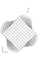
例えば、図1には、上面10が底面(この図には示されていない)に対して回転しているゴム製のブロック20が表示されている。側面12は空間におけるねじれ面構造を有し、これらの縁14は交わって空間に曲線を形成する。図1に示されているブロック20では、このブロック20は立方体の形状をなしている。立方体の構造は数学的計算を単純化するので、後に説明される有限要素分析のためにこうした構造が選択された。ブロック20すなわちトレッド要素はもちろん、いかなる構造でもよく、当文書に開示されている本発明の基本的な原理と利点はいかなる構造にも適用され得る。図2には、図1と同じ「ねじられた」立方体のトレッド要素の側面が底面16にそって示されている。図3においては、図1に示されているブロックが更に10×10×10個の網目として表されている。体積を網目に分割することは一般的に、有限要素模型に関する分析には必要でありかつ有用である。トレッド要素の「ねじられた」状態は図3によって容易に判る。図4には、図3に示されているトレッド要素の側面が、その上面10に対して直角にすなわち垂直にかけられた力によって変形され20%圧縮された後における状態を示している。同様に、図5は同じ変形のある同じトレッド要素であるブロック20の上面図である。
【0013】
図6では、ねじられたブロック20の垂直圧縮が実線24によって示され、また一方、このグラフでは「正常な立方体」と呼ばれている、ねじられていない立方体の垂直圧縮は、破線26で示されている。正常な立方体はいくらか堅固なので、ねじられたブロック20は正常の立方体よりも大きく垂直方向にたわんでいる。
【0014】
図7では、グラフはねじられたブロック20が垂直軸を中心にトルクを発生させていることを示している。この特性は独特で新しいものであって、今までにRASTの問題に取り組んだタイヤ設計者には利用されていなかったものである。例えば図7では、線28は、ブロックのたわみが増すにつれて増大する垂直軸を中心に発生したポンド×インチ単位のトルクを示している。菱形のマークのある線30は正常な立方体に発生する反応トルクを示していることに留意されたい。対照的に、「正常な立方体」のトレッド要素は、絶対にトルクを発生させない。線30はグラフ2の水平軸に一致しており、正常な立方体は反応トルクを生成しないことを示している。ねじられたブロック20のこうした特性、すなわち個々のトレッド要素またはトレッド踏み面にトルクを発生させる特性は、残留復原トルク(RSAT)によって生じる問題の解決に重要であると、考えられている。
【0015】
本発明を検討しそして研究するために実施された有限要素分析によると、底面に対して上面が45度回転しているこのような立方体に似るように修正された1インチ×1インチ(2.54cm×2.54cm)の正常な立方体は、500ポンドの半径方向すなわち垂直の荷重をかけられたとき、約5ポンド×インチのトルクを発生させる。
【0016】
図8および図9を説明すると、応力とひずみとそしてトルクとの関係を分析する様々な科学的方法がこれらのブロックに適用された。それぞれの場合において、適用された物質の法則に関係なく、図1に示されているねじられたブロック20は一貫して、半径方向すなわち垂直方向にかけられた圧縮荷重によってトルクを発生することが示されている。図10と11によると、有限要素分析の結果は、用いられている網目の密度に関係なく、本質的に同じであった。
【0017】
より現実的なトレッド要素の形態に初期の有限要素分析を適用するために、図12Aと12B、そして図13Aと13Bに示されているトレッド要素が開発された。各トレッド要素のための有限要素の網目もまた開発された。図12Aと12Bに示されているトレッド要素48は15度のねじりがあるが、図13Aと13Bに示されているトレッド要素48は5度のねじりがある。図14に示されているような有限要素の網目が開発された。
その結果、各トレッド要素48は回転角度の方向に復原トルクを発生させることが示された。例えば、図12Aと12Bでは、上面40は矢印50の方向に逆時計周りに15度ねじられている。したがって、トレッド要素48の上面40が50ポンドの半径方向にかかる力を受けたとき、このトレッド要素48の上面40の圧縮によって、矢印50の方向に約1.1ポンド×インチの反応トルクが発生する。
【0018】
図14を参照すると、実寿命のタイヤトレッド要素48のより精密な有限要素模型が作成されている。図14に示されているトレッド要素48は、グッドイヤータイヤ&ラバー社によって製造され、商標インヴィクタGA(L)として販売されているタイヤトレッドのトレッド要素である。図14に示されているトレッド要素は有限要素模型により様々な分析を受け、その結果が分析され、そして図15のグラフに表されている。この図で明らかなように、ねじり角が大きくなると、トレッド要素によって生じる復原トルクが増大する。例えば、線56は、図14に示されているような15度のねじりを有するトレッド要素によって生じる復原トルクを表している。線58は、5度のねじりを有する同様なトレッド要素によって生じたトルク量を示している。線60は、15度のねじりを有する1インチ×1インチ×0.277インチ(0.704cm)の中実ブロックによって生じるトルク量を表している。
【0019】
本発明は上記において好ましい1実施例について説明された。明らかに、この明細書を読みかつ理解すれば、当該技術の専門家にとってはその修正や変更は可能であろう。こうした修正および変更は全て、添付の請求の範囲内またはそれと同等なものの範囲内において本発明に含まれるものとする。
【図面の簡単な説明】
本発明は幾つかの部分および幾つかの部分の配置における具体的な形態を示しており、これらの中から1つの好ましい実施例が、本発明の一部を形成する下記の添付の図面を参照しながら上記のように説明された。
【図1】上面が底面に対してねじられている中実の立体を成す全体構造を有するゴムの中実ブロックの上面図である。
【図2】図1に示されているゴムの中実ブロックの側面図である。
【図3】1,000個の有限要素である10×10×10の網目に分けられている図1に示されているゴムのブロックの上面図である。
【図4】図3に示されているゴムのブロックの側面図であり、ここで太線で示されているのは、圧縮されていず、たわみもない状態のブロックであり、そして細線で示されているのは、圧縮されて、たわんでいる状態のブロックである。
【図5】図4に示されている10×10×10個の網目の上面図で、この図でたわんでいないブロックは太線で示され、そして上面への標準荷重のために、たわんでいるブロックは細線で示されている。
【図6】正常な立方体に比較された、ねじられたブロックの垂直圧縮を示すグラフであって、この正常な立方体は1インチ×1インチ×1インチの寸法であり、そしてこのねじられてブロックは45度の回転を加えた同じ公称寸法を有する。
【図7】正常の立方体に対して、ねじられたブロックの垂直圧縮により発生した反応トルクの計算値を示すグラフである。
【図8】ねじられたブロックの垂直圧縮に及ぼす様々な物質の影響を示すグラフである。
【図9】捩じられたブロックの反応トルクに対する様々な物質の影響を示すグラフである。
【図10】ねじられたブロックの垂直圧縮に及ぼす網目密度の影響を示すグラフである。
【図11】ねじられたブロックの反応トルクに及ぼす網目密度の影響を示す、グラフである。
【図12】(A)は上面は太線で示され、かつ点線で示されている底面に対し15度回転させられているトレッド要素の上面図である。(B)は(A)に示されているトレッド要素の上面図であるが、細線は除去されて示されている。
【図13】(A)は5度回転されているトレッド要素の上面図である。(B)は(A)に示されているトレッド要素の上面図であるが、細線は除去されて示されている。
【図14】本明細書に開示されている有限要素研究の対象であったトレッド要素の有限要素である網目の透視図である。
【図15】トレッド要素にかかる垂直な力によって生じる復原トルクを示し、かつねじり15度のグッドイヤー社のインヴィクタGA(L)『リアルワールド』とねじり5度のグッドイヤー社のインヴィクタGA(L)『リアルワールド』と、そしてインヴィクタGA(L)のラグと同じスリップ防止のための深さ(0.277インチ)を有しているねじり15度の1インチ×1インチの正方形のトレッドブロックとを比較するグラフである。
【符号の説明】
10 上面
12 側面
14 縁
16 底面
20 ブロック(トレッド要素)
24 ねじられた立方体
26 正常な立方体
28 ねじられた立方体
30 正常な立方体
40 上面
48 トレッド要素
50 矢印[0001]
BACKGROUND OF THE INVENTION
The present invention relates to the art of pneumatic tires, and more particularly to the field of pneumatic tires characterized by tread elements that generate torque on individual tread elements or on the entire tread surface of a tire tread.
[0002]
[Prior art]
One of the challenges facing tire designers is “residual restoring torque” or “RSAT”. Conventional tire treads have been designed to reduce the undesirable effects of RSAT. For example, European Patent Application No. 0,605,849 argues that the residual restoring torque of a tire can be compensated by modifying the lateral grooves of selected ribs with a draft. A rib-type tire tread is disclosed.
[0003]
[Problems to be solved by the invention]
The present invention aims to design a new and improved tire tread which is effective in use while providing better and more advantageous overall results and which otherwise overcomes the above-mentioned problems.
[0004]
[Means for Solving the Problems]
The present invention provides a new improved tire design with a new improved tire tread suitable to address the RSAT problem. .
[0005]
DETAILED DESCRIPTION OF THE INVENTION
In particular, according to the present invention, the tread element in the tire tread has a center of gravity, and when the tread element is compressed, an actual torque is generated about a radial line passing through the centroid.
[0006]
In another aspect of the invention, the tire tread includes a tread element having an upper surface and a plurality of side surfaces. These sides extend radially outward from the tread bottom and intersect to form a curved edge in space.
[0007]
According to yet another aspect of the invention, the tire tread has a tread element. The tread element has a top surface that is spaced from the bottom surface of the tread in a radial direction. The tread element has a plurality of side surfaces extending between a top surface and a bottom surface. The bottom surface of the tread is generally a projection radially inward of the top surface of the tread element onto the tread surface, ie, the projection of the top surface onto the bottom surface. The upper surface of the tread element is shaped to rotate about a radial line passing through the centroid of the upper surface, and has a side surface that forms a curve in the space.
[0008]
Other benefits and advantages of the present invention will be apparent to those skilled in the art of the present invention upon reading and understanding the following detailed description.
[0009]
The present invention may also be better understood by the following definitions that apply to both this specification and the appended claims. “Axial” or “axially” is used in this document to refer to a line or direction parallel to the axis of rotation of the tire. “Circumferential” refers to a line or direction along the circumference of the surface of the annular tread perpendicular to the axial direction. The “circumferential surface” refers to a surface that is perpendicular to the tire rotation axis and passes through the center of the tread. “Tread” means the contact area or contact area between the flat surface and the tire tread at zero speed and under standard load and standard pressure, which is also occupied by the tread element and the groove. An area is included.
[0010]
“Side” means the axial direction. “Predecessor” refers to the portion or part of the tread that first contacts the ground within a series or portion of the tread that sequentially contacts the ground as the tire rotates in a preferred direction. The “inner tread surface” refers to a tread portion between the protruding tread lugs. The “outer tread surface” or “surface that bites into the ground” refers to the outermost surface in the radial direction of the protruding tread lug. “Radial” or “radially” means a direction radially toward or away from the axis of rotation of the tire, “following” means that the tire is rotating in a preferred direction. Sometimes, it refers to the part or part of the tread that comes in contact with the ground lastly, in the series or part of the tread that comes into contact with the ground one after another.
[0011]
【Example】
The following description is made with particular reference to the following drawings, which are for the purpose of illustrating a preferred embodiment of the invention only and not for the purpose of limiting the invention. 2 represents a tire tread and a tread element of the tire, and a graph showing the characteristics of the tread element and the tire tread. In general, a plurality of tread elements of a tire have vertically oriented side surfaces that meet each other to form edges. These edges are generally straight lines radially toward the tire's axis of rotation. The present invention is specifically configured to accommodate tire residual restoring torque (RSAT). In one embodiment of the invention, the tread element of the tire utilizes a “twisted” orientation, and the sides of the tread element are actually curved surfaces in space and curved in space. Cross to form an edge that draws. To understand the orientation of this tread element, imagine a rubber cubic block whose top surface is twisted at an angle with respect to the bottom surface.
[0012]
For example, FIG. 1 shows a
[0013]
In FIG. 6, the vertical compression of the
[0014]
In FIG. 7, the graph shows that the
[0015]
According to finite element analysis performed to study and study the present invention, a 1 inch by 1 inch (2. .1) modified to resemble such a cube whose top surface is rotated 45 degrees relative to the bottom surface. A normal cube (54 cm × 2.54 cm) generates about 5 pounds × inch of torque when subjected to a radial or vertical load of 500 pounds.
[0016]
Referring to FIGS. 8 and 9, various scientific methods for analyzing the relationship between stress, strain, and torque were applied to these blocks. In each case, regardless of the applied material law, the
[0017]
To apply initial finite element analysis to more realistic tread element configurations, the tread elements shown in FIGS. 12A and 12B and FIGS. 13A and 13B were developed. A finite element mesh for each tread element was also developed. The
As a result, it was shown that each
[0018]
Referring to FIG. 14, a more precise finite element model of a real-life
[0019]
The invention has been described with reference to a preferred embodiment. Obviously, after reading and understanding this specification, modifications and changes will occur to those skilled in the art. All such modifications and changes are intended to be included herein within the scope of the appended claims or equivalents thereof.
[Brief description of the drawings]
The present invention shows specific embodiments in several parts and arrangements of several parts, one of which, preferred embodiments, refers to the following attached drawings forming part of the present invention. While explained above.
FIG. 1 is a top view of a solid block of rubber having a solid solid overall structure with the top surface twisted relative to the bottom surface.
FIG. 2 is a side view of the solid block of rubber shown in FIG.
FIG. 3 is a top view of the rubber block shown in FIG. 1 divided into a 10 × 10 × 10 mesh of 1,000 finite elements.
FIG. 4 is a side view of the rubber block shown in FIG. 3, where the bold line is the uncompressed and unbent block and is shown in thin lines It is a block that is compressed and bent.
5 is a top view of the 10 × 10 × 10 mesh shown in FIG. 4, in which the undeflected blocks are shown in bold lines and are deflected due to the standard load on the top surface Blocks are indicated by thin lines.
FIG. 6 is a graph showing the vertical compression of a twisted block compared to a normal cube, the normal cube measuring 1 inch × 1 inch × 1 inch, and the twisted block Have the same nominal dimensions plus 45 degrees rotation.
FIG. 7 is a graph showing calculated values of reaction torque generated by vertical compression of a twisted block with respect to a normal cube.
FIG. 8 is a graph showing the effect of various materials on the vertical compression of a twisted block.
FIG. 9 is a graph showing the effect of various materials on the reaction torque of a twisted block.
FIG. 10 is a graph showing the effect of mesh density on the vertical compression of twisted blocks.
FIG. 11 is a graph showing the effect of mesh density on the reaction torque of a twisted block.
FIG. 12A is a top view of a tread element whose top surface is indicated by a thick line and rotated 15 degrees with respect to the bottom surface indicated by a dotted line. (B) is a top view of the tread element shown in (A), but with the fine lines removed.
FIG. 13A is a top view of a tread element rotated 5 degrees. (B) is a top view of the tread element shown in (A), but with the fine lines removed.
FIG. 14 is a perspective view of a mesh that is a finite element of a tread element that was the subject of the finite element research disclosed herein.
FIG. 15 shows the restoring torque generated by the vertical force applied to the tread element, and the Goodyear Invicta GA (L) “Real World” with a twist of 15 degrees and the Goodyear Invicta GA (L) “Real with a twist of 5 degrees Compare "World" and a 15-inch torsional 1 "x 1" square tread block with the same anti-slip depth (0.277 ") as the Invicta GA (L) lug It is a graph.
[Explanation of symbols]
10
24
Claims (3)
該トレッド要素は、図心と、上面と、該上面から半径方向内側にずれた位置にある底面と、該上面と該底面との間で半径方向に延びている複数の側面とを有し、
該トレッド要素は、前記複数の側面がねじられ、かつ前記上面が前記底面に対して、前記図心を通る半径方向の線の回りに所定の角度だけ相対的に回転させられるようにねじられ、
前記トレッド要素が圧縮されたときに、前記図心を通過する前記半径方向の線の回りに実トルクが発生させられるタイヤ。Having a tread including a tread element;
The tread element has a centroid, a top surface, a bottom surface that is offset radially inward from the top surface, and a plurality of side surfaces that extend radially between the top surface and the bottom surface,
The tread element is twisted such that the side surfaces are twisted and the top surface is rotated relative to the bottom surface by a predetermined angle about a radial line passing through the centroid;
Wherein when the tread element is compressed, the tire actual torque about the radial line is generated that passes through the centroid.
Applications Claiming Priority (2)
| Application Number | Priority Date | Filing Date | Title |
|---|---|---|---|
| US08/496657 | 1995-06-29 | ||
| US08/496,657 US5669993A (en) | 1995-06-29 | 1995-06-29 | Tire tread elements with built-in twist |
Publications (2)
| Publication Number | Publication Date |
|---|---|
| JPH0911707A JPH0911707A (en) | 1997-01-14 |
| JP3759237B2 true JP3759237B2 (en) | 2006-03-22 |
Family
ID=23973590
Family Applications (1)
| Application Number | Title | Priority Date | Filing Date |
|---|---|---|---|
| JP16612896A Expired - Fee Related JP3759237B2 (en) | 1995-06-29 | 1996-06-26 | Tire tread element with built-in twist |
Country Status (10)
| Country | Link |
|---|---|
| US (1) | US5669993A (en) |
| EP (1) | EP0751013B1 (en) |
| JP (1) | JP3759237B2 (en) |
| KR (1) | KR970000622A (en) |
| CN (1) | CN1055046C (en) |
| BR (1) | BR9602820A (en) |
| CA (1) | CA2159132A1 (en) |
| DE (1) | DE69608739T2 (en) |
| ES (1) | ES2146809T3 (en) |
| MX (1) | MX9602369A (en) |
Families Citing this family (14)
| Publication number | Priority date | Publication date | Assignee | Title |
|---|---|---|---|---|
| JP4390879B2 (en) * | 1997-12-24 | 2009-12-24 | 株式会社ブリヂストン | Pneumatic tire |
| DE69930927T2 (en) * | 1998-11-20 | 2006-09-14 | Bridgestone Corp. | TIRE |
| USD426502S (en) * | 1999-09-29 | 2000-06-13 | The Goodyear Tire & Rubber Company | Tire tread |
| US7090735B2 (en) * | 2001-08-06 | 2006-08-15 | Bridgestone/Firestone North American Tire, Llc | Method of compensating for residual aligning torque (RAT) |
| KR100502555B1 (en) * | 2003-07-09 | 2005-07-21 | 한국타이어 주식회사 | Method for controlling PRAT as tire properties |
| US7323003B2 (en) * | 2004-02-13 | 2008-01-29 | Boston Scientific Scimed, Inc. | Centering intravascular filters and devices and methods for deploying and retrieving intravascular filters |
| JP4414788B2 (en) * | 2004-03-04 | 2010-02-10 | 株式会社ブリヂストン | Rough terrain tire |
| US7392832B2 (en) * | 2004-12-28 | 2008-07-01 | The Goodyear Tire & Rubber Company | Pneumatic tire having tread blocks with skewed walls |
| US7290578B2 (en) * | 2004-12-30 | 2007-11-06 | The Goodyear Tire & Rubber Company | Tire tread having a tread block with an undercut design |
| US8447578B2 (en) * | 2008-05-07 | 2013-05-21 | Bridgestone Americas Tire Operations, Llc | Method of designing a tire having a target residual aligning torque |
| JP4916499B2 (en) * | 2008-11-17 | 2012-04-11 | 東洋ゴム工業株式会社 | Pneumatic tire |
| US9278582B2 (en) | 2010-12-21 | 2016-03-08 | Bridgestone Americas Tire Operations, Llc | Tire tread having developing grooves |
| JP6805738B2 (en) * | 2016-11-08 | 2020-12-23 | 住友ゴム工業株式会社 | Tires for running on rough terrain |
| JP6834423B2 (en) * | 2016-12-01 | 2021-02-24 | 住友ゴム工業株式会社 | Motorcycle tires for running on rough terrain |
Family Cites Families (12)
| Publication number | Priority date | Publication date | Assignee | Title |
|---|---|---|---|---|
| US1349055A (en) * | 1918-06-27 | 1920-08-10 | Wesley N Forbes | Tire-tread |
| US1413190A (en) * | 1921-03-01 | 1922-04-18 | Rapson Frederick Lionel | Resilient wheel for vehicles |
| GB748078A (en) * | 1952-06-26 | 1956-04-18 | Alexander Eric Moulton | Improvements in mechanical energy storing devices or power accumulators |
| FR2382348A1 (en) * | 1977-03-03 | 1978-09-29 | Michelin & Cie | TIRE CASE TREAD |
| DE3664959D1 (en) * | 1985-10-31 | 1989-09-14 | Wieland Werke Ag | Finned tube with a notched groove bottom and method for making it |
| JPS62255203A (en) * | 1986-04-30 | 1987-11-07 | Bridgestone Corp | Pneumatic radial tire |
| JPH02241805A (en) * | 1989-03-16 | 1990-09-26 | Bridgestone Corp | Protruding element of pneumatic tire |
| US5016696A (en) * | 1989-10-11 | 1991-05-21 | The Goodyear Tire & Rubber Company | Self-cleaning tire tread |
| CN1019652B (en) * | 1990-07-07 | 1992-12-30 | 李石生 | Sweepback elastic support body tyre |
| JP2994008B2 (en) * | 1990-08-16 | 1999-12-27 | 株式会社ブリヂストン | Pneumatic radial tire |
| DE69206473T2 (en) * | 1991-05-09 | 1996-07-04 | Bridgestone Corp | Tire. |
| DE69303354T2 (en) * | 1992-12-30 | 1996-11-14 | Michelin Rech Tech | Tread that compensates for the remaining alignment torque |
-
1995
- 1995-06-29 US US08/496,657 patent/US5669993A/en not_active Expired - Lifetime
- 1995-09-26 CA CA002159132A patent/CA2159132A1/en not_active Abandoned
-
1996
- 1996-06-17 MX MX9602369A patent/MX9602369A/en unknown
- 1996-06-18 BR BR9602820A patent/BR9602820A/en not_active IP Right Cessation
- 1996-06-21 ES ES96110099T patent/ES2146809T3/en not_active Expired - Lifetime
- 1996-06-21 EP EP96110099A patent/EP0751013B1/en not_active Expired - Lifetime
- 1996-06-21 DE DE69608739T patent/DE69608739T2/en not_active Expired - Fee Related
- 1996-06-26 JP JP16612896A patent/JP3759237B2/en not_active Expired - Fee Related
- 1996-06-28 CN CN96108239A patent/CN1055046C/en not_active Expired - Fee Related
- 1996-06-28 KR KR1019960025076A patent/KR970000622A/en not_active Application Discontinuation
Also Published As
| Publication number | Publication date |
|---|---|
| CN1055046C (en) | 2000-08-02 |
| BR9602820A (en) | 1999-06-15 |
| EP0751013B1 (en) | 2000-06-07 |
| EP0751013A3 (en) | 1997-05-21 |
| CN1141247A (en) | 1997-01-29 |
| DE69608739D1 (en) | 2000-07-13 |
| CA2159132A1 (en) | 1996-12-30 |
| JPH0911707A (en) | 1997-01-14 |
| US5669993A (en) | 1997-09-23 |
| EP0751013A2 (en) | 1997-01-02 |
| DE69608739T2 (en) | 2000-11-23 |
| MX9602369A (en) | 1998-04-30 |
| ES2146809T3 (en) | 2000-08-16 |
| KR970000622A (en) | 1997-01-21 |
Similar Documents
| Publication | Publication Date | Title |
|---|---|---|
| JP3759237B2 (en) | Tire tread element with built-in twist | |
| JP3650342B2 (en) | Tire and wheel performance simulation method and apparatus | |
| JP3224089B2 (en) | Wheel drum durability evaluation method | |
| JPS63116907A (en) | Pneumatic tire mounting method on two-wheeled vehicle | |
| JP3927080B2 (en) | Tire simulation method | |
| JP2003118328A (en) | Method for predicting rolling resistance of tire | |
| JP4081330B2 (en) | Mechanical property simulation method and mechanical property simulation apparatus for composite material | |
| JP3431818B2 (en) | Simulation method of tire performance | |
| JP4401698B2 (en) | Tire performance simulation method and tire design method | |
| MXPA96002369A (en) | Tire tread elements with built-in twist | |
| US7006930B2 (en) | Method of analyzing tire pitch sequence based on lug stiffness variations | |
| JPH11153520A (en) | Method and apparatus for simulation of performance of tire | |
| JP4318971B2 (en) | Tire performance simulation method and tire design method | |
| JP3431817B2 (en) | Simulation method of tire performance | |
| JP4275991B2 (en) | Tire performance simulation method and tire design method | |
| Guo | Tire roller contact model for simulation of vehicle vibration input | |
| JPH0752613A (en) | Pneumatic radial tire for heavy load | |
| JP2002007489A (en) | Method for preparing tire finite element model | |
| JP3363443B2 (en) | Simulation method of tire performance | |
| JP6898155B2 (en) | Rotating body rolling analysis method, rotating body rolling analysis device, and program | |
| Balaramakrishna et al. | A study on the estimation of SWIFT model parameters by finite element analysis | |
| JP5320806B2 (en) | Rotating body simulation method | |
| JP4635562B2 (en) | Operation method of simulation apparatus | |
| JP2003240651A (en) | Physical quantity display method for tire | |
| JP2002022620A (en) | Method for simulating performance of tire |
Legal Events
| Date | Code | Title | Description |
|---|---|---|---|
| A977 | Report on retrieval |
Free format text: JAPANESE INTERMEDIATE CODE: A971007 Effective date: 20051025 |
|
| A131 | Notification of reasons for refusal |
Free format text: JAPANESE INTERMEDIATE CODE: A131 Effective date: 20051101 |
|
| A521 | Request for written amendment filed |
Free format text: JAPANESE INTERMEDIATE CODE: A523 Effective date: 20051107 |
|
| TRDD | Decision of grant or rejection written | ||
| A01 | Written decision to grant a patent or to grant a registration (utility model) |
Free format text: JAPANESE INTERMEDIATE CODE: A01 Effective date: 20051130 |
|
| A61 | First payment of annual fees (during grant procedure) |
Free format text: JAPANESE INTERMEDIATE CODE: A61 Effective date: 20051228 |
|
| R150 | Certificate of patent or registration of utility model |
Free format text: JAPANESE INTERMEDIATE CODE: R150 |
|
| FPAY | Renewal fee payment (event date is renewal date of database) |
Free format text: PAYMENT UNTIL: 20090113 Year of fee payment: 3 |
|
| FPAY | Renewal fee payment (event date is renewal date of database) |
Free format text: PAYMENT UNTIL: 20100113 Year of fee payment: 4 |
|
| LAPS | Cancellation because of no payment of annual fees |