JP3754229B2 - Vibration reduction control method and apparatus for variable magnetoresistive linear motor - Google Patents
Vibration reduction control method and apparatus for variable magnetoresistive linear motor Download PDFInfo
- Publication number
- JP3754229B2 JP3754229B2 JP10174099A JP10174099A JP3754229B2 JP 3754229 B2 JP3754229 B2 JP 3754229B2 JP 10174099 A JP10174099 A JP 10174099A JP 10174099 A JP10174099 A JP 10174099A JP 3754229 B2 JP3754229 B2 JP 3754229B2
- Authority
- JP
- Japan
- Prior art keywords
- armature
- stator
- linear motor
- phase current
- phases
- Prior art date
- Legal status (The legal status is an assumption and is not a legal conclusion. Google has not performed a legal analysis and makes no representation as to the accuracy of the status listed.)
- Expired - Fee Related
Links
Images


Classifications
-
- H—ELECTRICITY
- H02—GENERATION; CONVERSION OR DISTRIBUTION OF ELECTRIC POWER
- H02P—CONTROL OR REGULATION OF ELECTRIC MOTORS, ELECTRIC GENERATORS OR DYNAMO-ELECTRIC CONVERTERS; CONTROLLING TRANSFORMERS, REACTORS OR CHOKE COILS
- H02P25/00—Arrangements or methods for the control of AC motors characterised by the kind of AC motor or by structural details
- H02P25/02—Arrangements or methods for the control of AC motors characterised by the kind of AC motor or by structural details characterised by the kind of motor
- H02P25/08—Reluctance motors
-
- H—ELECTRICITY
- H02—GENERATION; CONVERSION OR DISTRIBUTION OF ELECTRIC POWER
- H02K—DYNAMO-ELECTRIC MACHINES
- H02K41/00—Propulsion systems in which a rigid body is moved along a path due to dynamo-electric interaction between the body and a magnetic field travelling along the path
- H02K41/02—Linear motors; Sectional motors
- H02K41/03—Synchronous motors; Motors moving step by step; Reluctance motors
-
- H—ELECTRICITY
- H02—GENERATION; CONVERSION OR DISTRIBUTION OF ELECTRIC POWER
- H02K—DYNAMO-ELECTRIC MACHINES
- H02K5/00—Casings; Enclosures; Supports
- H02K5/04—Casings or enclosures characterised by the shape, form or construction thereof
- H02K5/16—Means for supporting bearings, e.g. insulating supports or means for fitting bearings in the bearing-shields
- H02K5/173—Means for supporting bearings, e.g. insulating supports or means for fitting bearings in the bearing-shields using bearings with rolling contact, e.g. ball bearings
-
- H—ELECTRICITY
- H02—GENERATION; CONVERSION OR DISTRIBUTION OF ELECTRIC POWER
- H02K—DYNAMO-ELECTRIC MACHINES
- H02K5/00—Casings; Enclosures; Supports
- H02K5/24—Casings; Enclosures; Supports specially adapted for suppression or reduction of noise or vibrations
Landscapes
- Engineering & Computer Science (AREA)
- Power Engineering (AREA)
- Physics & Mathematics (AREA)
- Chemical & Material Sciences (AREA)
- Combustion & Propulsion (AREA)
- Electromagnetism (AREA)
- Linear Motors (AREA)
- Control Of Linear Motors (AREA)
- Control Of Electric Motors In General (AREA)
Description
【0001】
【発明の属する技術分野】
本発明は可変磁気抵抗リニアモータにおける振動の大きさ及び前記振動に対する感度の両方を減少させるための方法およびその装置に関する。
【0002】
【従来の技術】
迅速な整定時間および精密な位置決めを必要とする高精度サーボシステムにおいて、当該システムが必要とする速度ループ帯域幅の周波数範囲内のあらゆる振動は、安定性に関して重要な制御システムの問題を生じさせる。これらの条件が高次の非線形または多変数依存である場合には、問題は更に深刻になる。
【0003】
【発明が解決しようとする課題】
可変磁気抵抗リニアモータを使用する高精度位置決めシステムにおいて、これらの振動問題は、主として、当該システムがゆっくり移動中か又は所要位置に接近中における時点において発生する。これら振動の一原因は、モータの固定子及び電機子と関連した法線方向の大きい力と、固定子、電機子、ベアリング、整流、フィードバック機構、等々の間の相互作用であり、これらの原因は非線形振動に共振振動数を励起させる。
【0004】
この種のモータが高加速運転中は、当該モータの相電流は相対的に大きい。これらの大電流は、対面するモータコアの間に強い磁気(法線方向)引力を発生させる。この強い法線方向の力は、モータの機械部品に予負荷をかけること、および、システム内のあらゆるヒステリシス又は「スロップ」の除去を援助する。ただし、モータは、その負荷を所要位置の近くに位置決めすると、当該モータの相電流が減少し、それによって法線方向の力を減少させ、機械システムを弛緩させる。このような剛性の効果的な減少は速度ループ安定性に悪影響を及ぼし、好ましくない共振を発生させる。
【0005】
この種の振動を除去または制御する一方法は、速度ループ帯域幅を狭くするか、或いは、当該システム内の摩擦を増加することである。ただし、これら提案済みの解決方法は、整定時間、精度、及び、温度上昇の観点から当該システムの性能に負の影響を与え兼ねない。他の方法は、例えば、ローパスフィルタ又はノッチフィルタのような低次数線形フィルタを使用することである。前記の振動/共振振動数は所要のシステム帯域幅内に含まれるので、これらの方法は速度ループ帯域幅に重要な影響を及ぼすはずである。
【0006】
【課題を解決するための手段】
従って、本発明の目的は、その振動が制御または低減される可変磁気抵抗リニアモータを提供することにある。
【0007】
本発明の他の目的は、可変磁気抵抗リニアモータの固定子と電機子との間に機械式ダンパを提供することにある。
【0008】
本発明の更なる目的は、固定子と電機子の間の法線方向の力が所要水準以上に保持される可変磁気抵抗リニアモータを提供することにある。
【0009】
本発明の更なる他の目的は、制御フィードバックループを条件付きでフィルタリングする機能を有する可変磁気抵抗リニアモータを提供することにある。
【0010】
前述および他の目的は、本発明の第1の態様に従い、固定子及び固定子の長さに沿って可動であるように設置された電機子を備えた可変磁気抵抗リニアモータによって達成される。電機子ベアリングは機械式振動ダンパを介して電機子へ取付けられ、かつ固定子の振動がベアリングに伝達されて振動ダンパにおいて消散されるように固定子に接触する。
【0011】
本発明の第2の態様において、固定子に対する電機子に関する位置データを得るために、センサが電機子へ取付けられる。次に、コントローラ、前記の位置データおよび所要の力の値に基づいて、モータの位相に関して必要な相電流を計算する。電機子と固定子の間における法線方向の最小の力を維持するように、相電流が算定される。
【0012】
本発明の第3の態様において、電機子が所要位置から所定距離内に所在する場合に、条件付きフィルタが用いられる。条件付きフィルタは、遅延時間の後で、所定の範囲への速度フィードバックをクランプし、同時に、速度ループ利得を減少させる。
【0013】
本発明のこれらの及び他の目的、特徴機能、及び、利点は、添付図面と関連した好ましい実施例に関する以下の詳細な記述から明白であり、十分に理解されるはずである。
【0014】
【発明の実施の形態】
図1は本発明に基づく可変磁気抵抗リニアモータ1を示す。モータ1は両側に歯22を備えた固定子20を有する。固定子20は固定子サポート12により安定したベース10に取付けられる。電機子アセンブリ30は固定子20の周りに取付けられ、固定子20に沿って可動であるように線形ベアリング36によって支持される。電機子アセンブリ30は、電機子キャリッジ32に取り付けられた2個の電機子モジュール34を有する。センサ90も同様にキャリッジ32に取り付けられ、固定子20に沿って電機子アセンブリ30の位置を精密に記憶するように線形エンコーダ14と相互にやりとりする。
【0015】
図2から4までに示すように、各電機子モジュール34は、独立に結合した三相電機子である。モジュール34はキャリッジ32に取付けられ、2個のモジュール34に対応する位相が単相として調和して作用するように配線される。換言すれば、電機子モジュール34の対応する位相の歯が固定子20の歯22と合致した配列状態となり、合致電流が対応する位相に供給されるように、モジュール34がキャリッジ32に取付けられる。他の構成、例えば、更に多くのモジュールを使用するか、或いは、ただ1つのモジュールを使用する上記以外の構成を用いても差し支えないが、これらの場合にも依然として本発明の範囲に含まれることは明白である。同様に、上記とは異なる個数の位相を使用しても差し支えない。
【0016】
図2および3から良く分かるように、各電機子モジュール34は、電機子モジュール34の2つのe‐コア80aおよび80bを支持する上側ハウジング40aと下側ハウジング40bによって構成される。上図に示す実施例において、上側ハウジング40aと下側ハウジング40bは同じであるので製造コストが節減される。ローラーベアリング70は、固定子20の底部に接触するように、シャフト72とプレート74によって下側ハウジング40bに取付けられる。電機子アセンブリ30がその長さに沿って移動するに際して、ベアリング70は固定子20を垂直方向に支持する。
【0017】
e‐コア80a/bは、固定子20の周りに配置された場合に当該固定子20の対面する両側面の歯22と相互作用するように、前記の対面する両側面に隣接してハウジング40a/b内に取付けられる(図4参照)。e‐コア80a/bの対応する相は相互に直線配置され、単相として作用するように同じ電流が前記位相に供給される。e‐コア80a/bは、ローラーベアリング60が取付けられているそれぞれの端部に2つのシャフト82(各々のe‐コア80a/bの4個のシャフト82)を備える。ローラーベアリング60は、e‐コア80a/bを固定子20から一定の距離に維持するようにベアリング表面24に沿った固定子20の側面に沿って歯22の上下に移動する(図1参照)。この構成により、電機子30は、図に示す実施例においては1000分の2ないし3インチ程度の著しく近接した距離を保って固定子20をたどることが可能になる(図4参照)。
【0018】
好ましい実施例におけるe‐コア80a/bはボルト62によってハウジング40a/b内に保持される。これらのボルト62の2個だけが図3に示されているが、各e‐コア80a/bに対して4個のボルト62が用いられいることを理解されたい(図2参照)。シャフト82はハウジング40a/b内の孔42にフィットする。孔42中でシャフト82が動くことを防止するために、ハウジング40a/b内の孔42はシャフト82に対して過渡的なすきまばめ状態にある。ボルト62はワッシャ64を貫通し、シャフト82にねじ込まれる。ハウジング40a/b内の孔42は片持ちバネ46の端部に位置する。前記端部はハウジング40a/bから機械工作によって作成されたものである。バネ46は、電機子30がその長さ方向に前後に移動する際に、電機子80a/bが固定子表面に従うこと可能にし、固定子20の僅かな曲がり又は心ずれ(ミスアラインメント)を補正する懸架(サスペンション)を提供する。ただし、上記以外のバイアスエレメント構成も利用可能であることは言うまでもない。
【0019】
図2を参照して、ハウジング40a/bの端部46にフェルトワイパ(図示せず)を取付けても差し支えない。これらのワイパは、酸化を防止するために固定子ベアリング表面24にオイルの薄い被膜を塗布するために役立つ。更に、前記のワイパは、ほこり及び破片がベアリング60と固定子20の間に付着することを防止する。
【0020】
(機械式ダンパ)
固定子20は疑似単純支持梁であるので、機械的振動の影響を極度に受け易い。本発明の第1の態様において、この振動は、励起源、即ち、電機子30において固定子20を減衰するために用いられる変換ダンパを用いて最小化される。図に示す実施例において、剛性のある細片50は、各モジュール34のe‐コア80aの1つに堅固に取付けられ、重合体(ポリマー)減衰グロメット56を介してモータハウジング40a/bに取り付けられる。従って、固定子20からのエネルギーは、電機子ベアリング60を介して剛性のある細片50に伝達され、減衰グロメット56内に消散される。これは、振動の大きさを減少させてシステムを一層安定した状態にする。
【0021】
図に示す実施例の各モジュール34においては、4個の剛性のある細片50がe‐コア80aに取付けられる。e‐コア80の各シャフト82(これにベアリング60が取付けられる)が細片50の1つの孔52にはめ込まれる。シャフト82と孔52との間のはめあいはぴったりしているので、固定子20の振動はベアリング60を介して細片50に伝達される。重合体(ポリマー)減衰グロメット56は、細片50のどちらの端部にも設けられた取付け孔54内に配置される。図3にはただ2個のグロメット56だけが示されているが、各細片50毎に2個のグロメット56が用いられ、図3に示すモジュール34には合計8個が用いられる。従って、細片50の端部は、ボルト58によってハウジング40a/bに取付けられ、前記ボルトはワッシャ59及びグロメット56を貫いて伸延し、孔44においてハウジング40a/bに固定される。グロメット56の摩耗を軽減するために、金属スリーブ57が各グロメット56に挿入され、ボルト58とグロメット56との間のバリヤとして作用する。
【0022】
図3に示すように、もう一方のe‐コア80bのシャフト82に間隔を提供するためにU字形の開口53が細片50に設けられている。もう一方のe‐コア80bの動きを妨害することを避けるために、これらのU字形開口53はシャフト82の外径よりも大きくしてある。これは、電機子が固定子20に従って懸垂され、電機子ベアリング60と接触状態を保つことを可能にするために必要である。
【0023】
上記とは別の代替構成も予想されるが、本発明の範囲に含まれるものとみなされることは言うまでもない。例えば、固定子20と接触するベアリング60はe‐コア80a/bに取付ける必要はなく、その代りに、例えば重合体グロメットのような機械式ダンパを経て電機子ハウジング40a/bへ直接取付けても差し支えない。このような場合には、e‐コア80a/bはハウジングへ堅固に取付けるか(細片50なしで)、または、既に述べたように取り付けても差し支えない。更に、既に述べたダンパ以外の機械式ダンパ、例えば、空気圧または油圧を用いるダンパを使用しても差し支えない。
【0024】
(電磁予負荷)
本発明の他の態様に基づき、更に振動を減少させるために、モータの位相整流システムにおける電磁予負荷が用いられる。
【0025】
図4および5を参照すれば、一般的なサーボモータ制御においては、モータに線運動方向の力を発生させるモータ位相を励起する整流が適用される。閉ループサーボ駆動システムにおいては、当該システムにおける位置/速度誤差に基づく出力を導出する閉ループ設計の結果として所要の力が得られる。当該システムは、これらの誤差値を用いて、所要とされる線形の関係にある力を得るために各位相に供給することが必要な電流を算定する。
【0026】
当該システムの非直線性を考慮して、前記の位相電流は、例えば、参考として米国特許No.5,621,294の例に従って制御される。前記の特許’294に従い、電機子30に取付けられたセンサ90(図1参照)は、固定子20に対する電機子30の位置を決定し、当該情報を整流コントローラ100及び運動コントローラ120に送る。運動コントローラ120は、このフィードバックに応答して速度コマンドを生成し、前記の速度コマンドを整流コントローラ100に送る。整流コントローラ100は、所要の横方向力を算定し、参照用テーブルと補間を用いてこの力を得るために必要な相電流を決定するために位置フィードバックデータと共に前記の情報を使用する。次に、相電流は増幅器110に送られ、この増幅器は当該電流を電機子30に送る。
【0027】
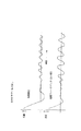
図6(a)は、14種の一定力水準に関して、1つの位相(B相)における電流を、位相Bの合致配列位置からのモータ変位の関数として示す。固定子20の歯22のピッチは6mmであり、電流の極性は歯の1ピッチ毎に変わるので(参照図4)、電流は12mm変位毎に周期性をもつ。位相AとCに関する電流波形は、位相Bに関するグラフ(図6(a))をそれぞれ8mm及び4mmだけ平行移動することによって求められる。図6(a)には、僅かに14種の個別の力水準が示されているに過ぎないが、ここに示す実施例においては、375の個別モータ位置に関して64種の力水準が用いられた。
【0028】
電機子30が所定の位置に接近すると、所要の線形の関係にある力(即ち、運動方向の力)はゼロに近付く。従って、図6(a)に示すように、目標位置に到達するまでモータ制御電流もゼロに近付く。目標位置に到達すると、図6(a)において「ゼロ力」とラベル表示されている所要の線形の関係にある力はゼロであり、全ての相電流はゼロに等しくなる。これは、電機子のe‐コア80a/bと固定子20との間の法線方向の引力も同時に減少させ、結果的にシステムの剛性を減少させる。
【0029】
モータの位相は、必要な線形の関係にある力とは関係なしに、常にある水準の励磁電流が流れていることを保証するために動的なずれ(オフセット)を整流システムに埋め込むことは本発明の1つの態様に基づく設計理念である。このように埋め込まれた電流はモータの固定子20と電機子30との間の法線方向の引力を維持し、剛性を所要水準に保持する。図6(b)は、本発明の実施例に基づくモータの変位の関数として位相Bにおける修正済み電流を示す。相電流は、モータによって生成される横方向の力に有意な影響を及ぼすことなしに或る水準の法線方向の力を維持するように選定される。換言すれば、1つの相のずれ(オフセット)電流によって発生する横方向の力のあらゆる変化は、他の2つの相のずれ(オフセット)電流によって相殺され、その結果、所要の横方向力が維持される。従って、「ゼロ力」水準の場合であっても、電機子30と固定子20との間に法線方向の力を維持するような或る水準の電流が当該位相に流れる。同時に、一方では他の2つの相の一方または両方にも或る水準の電流が流れて垂直方向の力を強化し、他方ではB相に生じたあらゆる横方向の力を相殺し、それによって、一切の横方向力成分を含まない正味の法線方向力が発生する。
【0030】
図6(b)に示す値を用いると、図に示す実施例のモータによって、ゼロ力水準の場合に、約80lbsの法線方向の引力が維持され、前記の値は第1から第8番目の力水準の場合に変化しない。更に高い力水準の場合には、この値は増加する。結果として剛性が付加されると、モータ振動の大きさを減少させ、システムを更に安定した状態にする。
【0031】
当該技術分野における熟練者にとって、本発明の電磁予負荷を実現するためにリニアモータが特許’294を用いる必要のないことは明白である。少なくとも1つの相に或る水準の電流が常時流れている場合には、法線方向の力が維持されるはずである。前述の必要条件を満足させるために用いられる電流は、力トランスデューサ、及び、モータの相電流を制御するための直流電源を用いて実験的に、或いは、理論的に見付けることが可能である。
【0032】
(条件付きフィルタリング)
本発明の第3の態様において、更に振動を減少させるために、制御フィードバックループの条件付きフィルタリングが用いられる。
【0033】
図1に示すコントローラとリニアモータの電機子との間のインタフェースに関する詳細なブロックダイアグラムを図7に示す。図に示すように、整流コントローラ100は、速度値(dx/dt)を求めるために、時間(t)に亙ってセンサ90によって読取った位置値(x)を微分するための微分ブロック104を有する。速度値(dx/dt)は速度フィルタ102を通って加算ブロック103に送られ、ここで、運動コントローラ120からの速度コマンドと比較される。比較結果は速度誤差制御ブロック101に送られ、ここで、速度ループ利得が供給されて、実際の力コマンドが出力される。整流ブロック105は、当該モータの各相に必要な電流(IA、IB、IC)を計算するために、速度誤差制御ブロック101から実際の力コマンドを、微分ブロック104から速度値(dx/dt)を、センサ90から位置値(x)を受け取る。これらの値は増幅器110に送られ、ここから、対応する増幅済み電流がモータの相に送られる。
【0034】
図8Aに示すように、先行技術に基づいて作動する場合、所要のモータ位置に到達すると、図7に示すシステムには揺動が生じる。その理由は、部分的に、モータの高速運転を達成するために、高速度ループ利得が用いられることに因る。本発明の条件付きフィルタリング(図8B)は、位置誤差(実際のモータ位置―所要位置)が或る規定値未満になるまで全速度ループ利得において駆動することによりこの問題を軽減する。運動コントローラ120のPID制御システム122によって通知された状態の位置誤差が規定値(Tf時点における)よりも小さい場合、条件付きフィルタ106が用いられる。前記フィルタにおいては、所要位置に到達した場合にシステムに起きることが経験的に予測される最大の外乱よりも大きいと経験的に判断される位置誤差の値が選択される。
【0035】
フィルタ106の第1ステージにおいては、当該システムが正常軌道を完了し、帯域幅を減少することなしに所要の位置に整定できるように遅延(タイムディレイ)が適用される。機械システムは巻き戻し(低加速度要求および関連した相電流の低下に起因して大きい法線方向の力が減少するにつれて剛性が減少すること)のための或る期間を必要とするので、前記の遅延は許容される。遅延の継続期間は、フィルタが用いられる位置から(既に述べた揺動が始まる以前の)所要位置における定常状態まで、電機子30が移動するために通常(即ち、条件付きフィルタを使用することなしに)必要とする時間よりも僅かに長い時間が選択される。遅延が(時点Tdにおいて)満了した場合、一旦所要位置に到達すると、当該所要位置を維持するための帯域幅必要条件が低下するので、速度誤差制御ブロック101によって供給される速度ループ利得が減少する。利得の減少は力コマンドを制限し、閉ループ感度を不安定な振動要素まで低下させる。
【0036】
フィルタ106の他の特徴は、加算ブロック103へ供給された速度データを所定の範囲に制限する速度クランプを速度フィルタ102において同時に導入することである(参照図8B)。これは、システムは基本的に停止状態にあり、位置を保持するためには低速における小さな変位のみを取り扱うことが必要であるという事実を利用する。あらゆる小さな変位振動(即ち、問題の非線形振動)は、それらの振動数に起因して高速要素を含む。この速度要素は、位置を保持する状態において予測されるあらゆる線形外乱よりも大きい。速度クランプは予測される最大の外乱要素の速度フィードバックを制限する。従って、速度クランプは、速度フィードバックされる値にクランプを供給することによって振動に対するシステムの感度を減少させる。低速なあらゆる位置的小外乱はフィルタのクランプの大きさによって影響されず、位置を維持するためにシステムが正常に反応することを可能にすることは言うまでもない。
【0037】
位置誤差が条件付きフィルタによって規定された値より大きい場合には(所要位置または大きい外乱のどちらかの変化に起因する)、条件付きフィルタは取り除かれ、前記の規定値よりも小さい位置誤差を再び期待するように初期化される。図8Bに示すように、このフィルタリング作用は機械的剛性の低下に関する当該システムの感度を低下させるが、所定位置に到着するために必要な整定時間に否定的には影響しない。
【0038】
図に示す実施例を用いて本発明について記述した。本願にとって有利に作用するような他の実施例、特徴、及び、変形例も特許請求の範囲に含まれることは、当該技術分野における通常の技術を持つ者にとって明白なはずである。
【図面の簡単な説明】
【図1】本発明に基づいた可変磁気抵抗リニアモータの立面図である。
【図2】図1のリニアモータの電機子モジュールの斜視図である。
【図3】図2の電機子モジュールの分解図である。
【図4】図1のモータの電機子モジュール及び固定子の概略図である。
【図5】コントローラと図1のリニアモータの電機子との間のインタフェースのブロックダイアグラムである。
【図6】(a)は14種の一定力水準に関して、先行技術によるリニアモータの1つの位相電流をモータの変位関数として示すグラフである。(b)は14種の一定力水準に関して、本発明によるリニアモータの1つの位相電流をモータの変位関数として示すグラフである。
【図7】コントローラと図1のリニアモータの電機子との間のインタフェースの更に詳細なブロックダイアグラムである。
【図8A】先行技術に従って駆動する図7のシステムの位置誤差および速度フィードバックのグラフである。
【図8B】本発明に従って駆動する図7のシステムの位置誤差および速度フィードバックのグラフである。
【符号の説明】
1 リニアモータ
20 固定子
30 電機子アセンブリ
80a e−コアa
80b e−コアb
90 センサ[0001]
BACKGROUND OF THE INVENTION
The present invention relates to a method and apparatus for reducing both the magnitude of vibration and the sensitivity to said vibration in a variable magnetoresistive linear motor.
[0002]
[Prior art]
In high precision servo systems that require rapid settling time and precise positioning, any vibration within the frequency range of the speed loop bandwidth that the system requires creates significant control system problems with respect to stability. The problem is exacerbated when these conditions are high-order nonlinear or multivariate dependent.
[0003]
[Problems to be solved by the invention]
In high precision positioning systems that use variable reluctance linear motors, these vibration problems mainly occur at times when the system is moving slowly or approaching the required position. One cause of these vibrations is the interaction between the large normal forces associated with the motor stator and armature and the stator, armature, bearing, commutation, feedback mechanism, etc. Excites the resonant frequency in a non-linear vibration.
[0004]
When this type of motor is operating at high acceleration, the phase current of the motor is relatively large. These large currents generate strong magnetic (normal direction) attractive forces between the facing motor cores. This strong normal force assists in preloading the motor's mechanical parts and removing any hysteresis or “slops” in the system. However, when a motor has its load positioned close to the required position, the motor's phase current decreases, thereby reducing the normal force and relaxing the mechanical system. Such an effective reduction in stiffness adversely affects speed loop stability and creates undesirable resonances.
[0005]
One way to eliminate or control this type of vibration is to reduce the velocity loop bandwidth or increase the friction in the system. However, these proposed solutions can negatively affect the performance of the system in terms of settling time, accuracy, and temperature rise. Another method is to use a low order linear filter such as a low pass filter or notch filter. These methods should have a significant impact on the velocity loop bandwidth, since the vibration / resonance frequency is within the required system bandwidth.
[0006]
[Means for Solving the Problems]
Accordingly, an object of the present invention is to provide a variable magnetoresistive linear motor whose vibration is controlled or reduced.
[0007]
Another object of the present invention is to provide a mechanical damper between a stator and an armature of a variable magnetoresistive linear motor.
[0008]
It is a further object of the present invention to provide a variable magnetoresistive linear motor in which the normal force between the stator and the armature is maintained above a required level.
[0009]
Still another object of the present invention is to provide a variable magnetoresistive linear motor having a function of conditionally filtering a control feedback loop.
[0010]
The foregoing and other objects are achieved in accordance with the first aspect of the present invention by a variable reluctance linear motor comprising a stator and an armature installed to be movable along the length of the stator. The armature bearing is attached to the armature via a mechanical vibration damper and contacts the stator so that the vibration of the stator is transmitted to the bearing and dissipated in the vibration damper.
[0011]
In a second aspect of the invention, a sensor is attached to the armature to obtain position data regarding the armature relative to the stator. The required phase current is then calculated for the motor phase based on the controller, the position data and the required force value. The phase current is calculated so as to maintain a minimum normal force between the armature and the stator.
[0012]
In the third aspect of the present invention, a conditional filter is used when the armature is located within a predetermined distance from the required position. The conditional filter clamps the speed feedback to a predetermined range after the delay time and at the same time reduces the speed loop gain.
[0013]
These and other objects, features and advantages of the present invention will be apparent from and will be fully understood from the following detailed description of the preferred embodiment, taken in conjunction with the accompanying drawings.
[0014]
DETAILED DESCRIPTION OF THE INVENTION
FIG. 1 shows a variable magnetoresistive linear motor 1 according to the present invention. The motor 1 has a
[0015]
As shown in FIGS. 2 to 4, each
[0016]
2 and 3, each
[0017]
The e-core 80a / b is adjacent to the opposite side surfaces of the
[0018]
The e-core 80a / b in the preferred embodiment is held in the
[0019]
Referring to FIG. 2, a felt wiper (not shown) may be attached to the
[0020]
(Mechanical damper)
Since the
[0021]
In each
[0022]
As shown in FIG. 3, a
[0023]
It will be appreciated that alternative configurations other than those described above are envisioned, but are considered to be within the scope of the present invention. For example, the bearing 60 in contact with the
[0024]
(Electromagnetic preload)
In accordance with another aspect of the invention, an electromagnetic preload in a motor phase rectification system is used to further reduce vibration.
[0025]
Referring to FIGS. 4 and 5, in general servo motor control, rectification is applied to excite a motor phase that causes the motor to generate a force in the direction of linear motion. In a closed loop servo drive system, the required force is obtained as a result of a closed loop design that derives an output based on position / velocity error in the system. The system uses these error values to calculate the current that needs to be supplied to each phase to obtain the required linearly related force.
[0026]
In view of the non-linearity of the system, the phase current can be calculated, for example, from US Pat. Controlled according to the example of 5,621,294. In accordance with the patent '294, a sensor 90 (see FIG. 1) attached to the
[0027]
FIG. 6 (a) shows the current in one phase (B phase) as a function of motor displacement from the matched alignment position in phase B for 14 constant force levels. Since the pitch of the
[0028]
When the
[0029]
Embedding a dynamic offset (offset) in the commutation system to ensure that the motor phase is independent of the required linear force and that a certain level of excitation current is always flowing. 1 is a design philosophy based on one aspect of the invention. The electric current embedded in this way maintains a normal direction attractive force between the
[0030]
Using the values shown in FIG. 6 (b), the normal force of about 80 lbs is maintained at the zero force level by the motor of the embodiment shown in FIG. It does not change when the power level is. For higher force levels, this value increases. As a result, the added stiffness reduces the magnitude of motor vibration and makes the system more stable.
[0031]
It will be apparent to those skilled in the art that a linear motor need not use patent '294 to achieve the electromagnetic preload of the present invention. If a level of current is always flowing in at least one phase, the normal force should be maintained. The current used to satisfy the aforementioned requirements can be found experimentally or theoretically using a force transducer and a direct current power source for controlling the motor phase current.
[0032]
(Conditional filtering)
In a third aspect of the invention, conditional filtering of the control feedback loop is used to further reduce vibrations.
[0033]
FIG. 7 shows a detailed block diagram regarding the interface between the controller shown in FIG. 1 and the armature of the linear motor. As shown in the figure, the
[0034]
As shown in FIG. 8A, when operating according to the prior art, the system shown in FIG. 7 will swing when the required motor position is reached. The reason is due in part to the use of high speed loop gain to achieve high speed operation of the motor. The conditional filtering of the present invention (FIG. 8B) alleviates this problem by driving at full speed loop gain until the position error (actual motor position-required position) is below some specified value. If the position error in the state notified by the
[0035]
In the first stage of the
[0036]
Another feature of the
[0037]
If the position error is greater than the value specified by the conditional filter (due to a change in either the required position or a large disturbance), the conditional filter is removed and the position error smaller than the specified value is again Initialized as expected. As shown in FIG. 8B, this filtering action reduces the sensitivity of the system with respect to the reduction in mechanical stiffness, but does not negatively affect the settling time required to arrive at a given location.
[0038]
The invention has been described using the example shown in the figure. It should be apparent to those skilled in the art that other embodiments, features, and modifications that may be beneficial to the present application are also within the scope of the claims.
[Brief description of the drawings]
FIG. 1 is an elevational view of a variable magnetoresistive linear motor according to the present invention.
FIG. 2 is a perspective view of an armature module of the linear motor of FIG.
FIG. 3 is an exploded view of the armature module of FIG. 2;
4 is a schematic diagram of an armature module and a stator of the motor shown in FIG. 1. FIG.
5 is a block diagram of an interface between a controller and the armature of the linear motor of FIG.
FIG. 6 (a) is a graph showing one phase current of a linear motor according to the prior art as a displacement function of the motor for 14 constant force levels. (B) is a graph showing one phase current of the linear motor according to the present invention as a displacement function of the motor for 14 constant force levels.
7 is a more detailed block diagram of the interface between the controller and the armature of the linear motor of FIG.
8A is a graph of position error and velocity feedback for the system of FIG. 7 driven according to the prior art.
8B is a graph of position error and velocity feedback for the system of FIG. 7 operating in accordance with the present invention.
[Explanation of symbols]
DESCRIPTION OF SYMBOLS 1
80b e-core b
90 sensors
Claims (31)
固定子と、
前記固定子の長さに沿って可動であり、前記固定子に近接して取付けられた電機子と、
前記固定子と接触し、前記電機子へ取り付けられた少なくとも1つのベアリングと、
前記電機子と前記ベアリングとの間に設けられた少なくとも1つの振動ダンパと、を備え、
前記振動ダンパは前記電機子と共に移動し、
前記固定子における振動は前記ベアリングに伝達され、前記電機子とベアリングとの間に配置された少なくとも1つの振動ダンパで消散されることを特徴とするリニアモータ。A linear motor,
A stator,
An armature that is movable along the length of the stator and is mounted in proximity to the stator;
At least one bearing in contact with the stator and attached to the armature;
And at least one vibration damper provided between the armature and the bearing ,
The vibration damper moves with the armature;
The linear motor is characterized in that the vibration in the stator is transmitted to the bearing and is dissipated by at least one vibration damper disposed between the armature and the bearing.
電機子ハウジングと、
前記ハウジング内に配置された少なくとも1つのコアとを備え、
前記少なくとも1つのベアリングが前記コアに取付けられ、前記コアが前記少なくとも1つの振動ダンパによって前記ハウジングへ接続されることを特徴とする請求項1に記載のリニアモータ。The armature,
An armature housing;
And at least one core disposed within the housing,
The linear motor according to claim 1, wherein the at least one bearing is attached to the core, and the core is connected to the housing by the at least one vibration damper.
前記電機子に関する位置データに基づいて相電流を計算し、前記相電流を前記少なくとも2つの位相へ供給するためのコントローラを備え、前記相電流は前記電機子と前記固定子との間で法線方向の最小の力を維持するように算定されることを特徴とする請求項1に記載のリニアモータ。The armature has at least two phases, and the linear motor further comprises:
A controller for calculating a phase current based on position data relating to the armature and supplying the phase current to the at least two phases, the phase current being normal between the armature and the stator; The linear motor according to claim 1, wherein the linear motor is calculated so as to maintain a minimum force in a direction.
前記電機子に関する位置データに基づいて相電流を計算し、前記相電流を前記少なくとも2つの位相へ供給するためのコントローラと、
前記電機子が所要位置から所定の距離内に位置するときに前記相電流を減少させるための手段とを備えることを特徴とする請求項1に記載のリニアモータ。The armature has at least two phases, and the linear motor is
A controller for calculating a phase current based on position data relating to the armature and supplying the phase current to the at least two phases;
The linear motor according to claim 1, further comprising means for reducing the phase current when the armature is located within a predetermined distance from a required position.
固定子と、
前記固定子の長さに沿って可動であり、前記固定子に接近して取付けられた電機子と、
前記固定子における振動を前記電機子へ伝達するための手段と、
前記電機子と接続し、当該電機子と共に移動可能であり、前記振動を消散させるための手段と、
を備えることを特徴とするリニアモータ。A linear motor,
A stator,
An armature that is movable along the length of the stator and is mounted close to the stator;
Means for transmitting vibrations in the stator to the armature;
Means for connecting to the armature, movable with the armature, and dissipating the vibration;
A linear motor comprising:
前記電機子に関する位置データに基づいて前記少なくとも2つの位相に関する相電流を計算するための手段を備え、
前記相電流は前記電機子と前記固定子との間において法線方向の最小の力を維持するように算定されることを特徴とする請求項9に記載のリニアモータ。The armature has at least two phases, and the linear motor is
Means for calculating a phase current for the at least two phases based on position data for the armature;
The linear motor according to claim 9, wherein the phase current is calculated so as to maintain a minimum normal force between the armature and the stator.
前記電機子が所要位置から所定の距離内に位置するときに前記相電流を減少させるための手段と、を更に備えることを特徴とする請求項9に記載のリニアモータ。Means for calculating a phase current based on the position data of the armature;
The linear motor according to claim 9, further comprising means for reducing the phase current when the armature is located within a predetermined distance from a required position.
前記電機子と共に移動可能であり、当該電気子と接続した少なくとも 1 つの振動ダンパを設定するステップと、
前記固定子から電機子へ前記振動を伝達するステップと、
前記少なくとも 1 つの振動ダンパによって前記電機子における前記振動を消散させるステップと、
を備えることを特徴とする方法。A method for reducing vibrations in a linear motor comprising a stator and an armature movable along the length of the stator and mounted in proximity to the stator,
Movable with said armature, setting at least one vibration damper connected with the armature,
Transmitting the vibration from the stator to the armature;
A step of dissipating Contact Keru the vibration to the armature by the at least one vibration damper,
A method comprising the steps of:
固定子と、
少なくとも2つの位相を有し、前記固定子の長さに沿って可動であり、前記固定子に近接して取付けられた電機子と、
前記電機子に関する位置データに基づいて位相電流を計算し、前記少なくとも2つの位相へ前記相電流を供給するためのコントローラと、
を備え、前記相電流は前記電機子と前記固定子との間において法線方向の最小の力を維持するように算定されることを特徴とする可変磁気抵抗リニアモータ。A variable reluctance linear motor,
A stator,
An armature having at least two phases, movable along the length of the stator, and mounted in proximity to the stator;
A controller for calculating a phase current based on position data relating to the armature and supplying the phase current to the at least two phases;
The variable current linear motor is characterized in that the phase current is calculated so as to maintain a minimum normal force between the armature and the stator.
固定子と、
少なくとも2つの位相を有し、前記固定子の長さに沿って可動であり、前記固定子に近接して取付けられた電機子と、
前記電機子に関する位置データに基づいて相電流を算定し、前記少なくとも2つの位相へ前記相電流を供給するための手段と、
を備え、前記相電流は前記電機子と前記固定子との間において法線方向の最小の力を維持するように算定されることを特徴とする可変磁気抵抗リニアモータ。A variable reluctance linear motor,
A stator,
An armature having at least two phases, movable along the length of the stator, and mounted in proximity to the stator;
Means for calculating a phase current based on position data relating to the armature and supplying the phase current to the at least two phases;
The variable current linear motor is characterized in that the phase current is calculated so as to maintain a minimum normal force between the armature and the stator.
前記固定子に対する前記電機子に関する位置データを獲得するステップと、
前記位置データに基づき前記少なくとも2つの位相に関する相電流を算定す
るステップと、
前記相電流を前記少なくとも2つの位相へ供給するステップと、
を備え、前記相電流は前記電機子と前記固定子との間において法線方向の最
小の力を維持するように算定されることを特徴とする方法。A method for reducing vibrations in a variable magnetoresistive linear motor comprising an armature, a stator and at least two phases, comprising:
Obtaining position data relating to the armature relative to the stator;
Calculating a phase current for the at least two phases based on the position data;
Supplying the phase current to the at least two phases;
The phase current is calculated to maintain a minimum normal force between the armature and the stator.
固定子と、
少なくとも2つの位相を有し、前記固定子の長さに沿って可動であり、前記固定子に近接して取付けられた電機子と、
前記電機子に関する位置データに基づいて位相電流を計算し、前記少なくとも2つの位相へ前記相電流を供給するためのコントローラと、
前記電機子が所要位置から所定距離内に位置するときに前記相電流を減少させるための手段と、を備え、
前記コントローラは速度データに基づいて前記相電流を算定し、前記相電流を減少させるための前記手段は前記速度データを所定の速度範囲に制限するための手段を備えることを特徴とする可変磁気抵抗リニアモータ。A variable reluctance linear motor,
A stator,
An armature having at least two phases, movable along the length of the stator, and mounted in proximity to the stator;
A controller for calculating a phase current based on position data relating to the armature and supplying the phase current to the at least two phases;
Means for reducing the phase current when the armature is located within a predetermined distance from a required position ,
The controller calculates the phase current based on speed data, and the means for reducing the phase current comprises means for limiting the speed data to a predetermined speed range. Linear motor.
固定子と、
少なくとも2つの位相を有し、前記固定子の長さに沿って可動であり、前記固定子に近接して取付けられた電機子と、
前記電機子に関する位置データに基づいて位相電流を計算し、前記少なくとも2つの位相へ前記相電流を供給するためのコントローラと、
前記電機子が所要位置から所定距離内に位置するときに前記相電流を減少させるための手段と、を備え
前記コントローラは速度ループ利得を用いることによって前記相電流を算定し、前記位相電流を減少させるための前記手段は前記速度ループ利得を減少させるための手段を備えることを特徴とする可変磁気抵抗リニアモータ。 A variable reluctance linear motor,
A stator,
An armature having at least two phases, movable along the length of the stator, and mounted in proximity to the stator;
A controller for calculating a phase current based on position data relating to the armature and supplying the phase current to the at least two phases;
Means for reducing the phase current when the armature is located within a predetermined distance from a required position, and wherein the controller calculates the phase current by using a speed loop gain and reduces the phase current. The variable magnetoresistive linear motor characterized in that the means for causing comprises means for reducing the speed loop gain.
固定子と、
少なくとも2つの位相を備え、前記固定子の長さに沿って可動であり、前記固定子に近接して取付けられた電機子と、
前記電機子の位置データおよび速度データに基づいて力コマンドを算定するための手段と、
前記電機子が所要位置から所定距離内に位置するときに前記力コマンドを減少させるための手段と、
前記力コマンドに基づいて位相電流を算定し、前記相電流を前記少なくとも2つの位相に供給するための手段と、
を備えることを特徴とする可変磁気抵抗リニアモータ。A variable reluctance linear motor,
A stator,
An armature comprising at least two phases, movable along the length of the stator, and mounted proximate to the stator;
Means for calculating a force command based on the position data and velocity data of the armature;
Means for reducing the force command when the armature is located within a predetermined distance from a required position;
Means for calculating a phase current based on the force command and supplying the phase current to the at least two phases;
A variable magnetoresistive linear motor comprising:
前記固定子に対する前記電機子の位置データを獲得するステップと、
前記電機子に関する速度データを決定するステップと、
前記位置データ及び前記速度データに基づいて力コマンドを算定するステップと、
前記電機子が所要位置から所定距離内に位置するときに前記力コマンドを減少させるステップと、
前記力コマンドに基づいて相電流を算定するステップと、
前記相電流を前記少なくとも2つの位相へ供給するステップと、
を備えることを特徴とする方法。A method for reducing vibrations in a variable magnetoresistive linear motor having an armature and a stator with at least two phases,
Obtaining position data of the armature with respect to the stator;
Determining speed data relating to the armature;
Calculating a force command based on the position data and the velocity data;
Reducing the force command when the armature is located within a predetermined distance from a required position;
Calculating a phase current based on the force command;
Supplying the phase current to the at least two phases;
A method comprising the steps of:
Applications Claiming Priority (2)
| Application Number | Priority Date | Filing Date | Title |
|---|---|---|---|
| US09/058,004 US6078114A (en) | 1998-04-08 | 1998-04-08 | Method and apparatus for vibration reduction/control in a variable reluctance linear motor |
| US09/058004 | 1998-04-08 |
Publications (2)
| Publication Number | Publication Date |
|---|---|
| JPH11332213A JPH11332213A (en) | 1999-11-30 |
| JP3754229B2 true JP3754229B2 (en) | 2006-03-08 |
Family
ID=22014071
Family Applications (1)
| Application Number | Title | Priority Date | Filing Date |
|---|---|---|---|
| JP10174099A Expired - Fee Related JP3754229B2 (en) | 1998-04-08 | 1999-04-08 | Vibration reduction control method and apparatus for variable magnetoresistive linear motor |
Country Status (4)
| Country | Link |
|---|---|
| US (1) | US6078114A (en) |
| EP (1) | EP0961392B1 (en) |
| JP (1) | JP3754229B2 (en) |
| DE (1) | DE69925670T2 (en) |
Families Citing this family (21)
| Publication number | Priority date | Publication date | Assignee | Title |
|---|---|---|---|---|
| JP3395155B2 (en) * | 1999-05-07 | 2003-04-07 | 株式会社日立製作所 | Linear motor and manufacturing method thereof |
| AU2001289294A1 (en) | 2000-03-30 | 2001-10-15 | Delware Capital formation | Variable reluctance motor with improved tooth geometry |
| AU2001251124A1 (en) * | 2000-03-30 | 2001-10-15 | Delaware Capital Formation | Variable reluctance motor |
| US20030038556A1 (en) * | 2000-03-30 | 2003-02-27 | Gieskes Koenraad Alexander | Variable reluctance motor |
| WO2001076045A2 (en) * | 2000-03-30 | 2001-10-11 | Delaware Capital Formation | Variable reluctance motor with reduced noise and vibration |
| JP2002034232A (en) * | 2000-07-18 | 2002-01-31 | Shinko Electric Co Ltd | Linear motor system and rotary motor |
| JP3945148B2 (en) * | 2000-11-02 | 2007-07-18 | 株式会社日立製作所 | XY table and XYZ table |
| JP3945150B2 (en) * | 2000-11-06 | 2007-07-18 | 株式会社日立製作所 | Linear motor |
| AU2002316370A1 (en) * | 2001-06-25 | 2003-01-08 | Delaware Capital Formation, Inc. | Variable reluctance motor |
| US6876107B2 (en) * | 2002-06-05 | 2005-04-05 | Jacobs Automation | Controlled motion system |
| US20050192519A1 (en) * | 2004-02-27 | 2005-09-01 | John Crunick | Motor assemblies and massage assemblies using the same |
| DE102004045992A1 (en) * | 2004-09-22 | 2006-04-06 | Siemens Ag | Electric machine |
| US20060131966A1 (en) * | 2004-12-16 | 2006-06-22 | Janisiewicz Stanley W | Motor, motor system, motor elements and method of assembly thereof |
| DE102005007489A1 (en) * | 2005-02-17 | 2006-08-24 | Siemens Ag | Woodworking machine with linear direct drive |
| US7187142B2 (en) * | 2005-05-25 | 2007-03-06 | Rockwell Automation Technologies, Inc. | Motor drive with velocity noise filter |
| US7109670B1 (en) * | 2005-05-25 | 2006-09-19 | Rockwell Automation Technologies, Inc. | Motor drive with velocity-second compensation |
| ES2345702B1 (en) * | 2008-11-10 | 2011-09-05 | Universitat Politècnica De Catalunya | SELF-SWITCHED RELUCTANCE MOTOR. |
| US8616134B2 (en) | 2009-01-23 | 2013-12-31 | Magnemotion, Inc. | Transport system powered by short block linear synchronous motors |
| US9032880B2 (en) | 2009-01-23 | 2015-05-19 | Magnemotion, Inc. | Transport system powered by short block linear synchronous motors and switching mechanism |
| US8729745B2 (en) | 2010-10-25 | 2014-05-20 | Asm Assembly Automation Ltd | Multiple-phase linear switched reluctance motor |
| EP3046801A4 (en) | 2013-09-21 | 2017-11-08 | Magnemotion, Inc. | Linear motor transport for packaging and other uses |
Family Cites Families (13)
| Publication number | Priority date | Publication date | Assignee | Title |
|---|---|---|---|---|
| US4282768A (en) * | 1979-05-25 | 1981-08-11 | Jsj Corporation | Vibration isolation mount for gear shifter |
| JPS62163557A (en) * | 1986-01-09 | 1987-07-20 | Shinko Electric Co Ltd | Vibration suppressing mechanism for linear pulse motor |
| JP2631363B2 (en) * | 1986-03-19 | 1997-07-16 | 愛知時計電機 株式会社 | Electric body |
| JPH0640423B2 (en) * | 1986-10-13 | 1994-05-25 | 富士通株式会社 | Positioning control method for information storage device |
| JPS63217965A (en) * | 1987-03-05 | 1988-09-12 | Shinko Electric Co Ltd | Linear motor |
| US5241229A (en) * | 1990-01-11 | 1993-08-31 | Sankyo Seiki Mfg. Co., Ltd. | Magnetic disc drive motor |
| JP3087305B2 (en) * | 1990-03-05 | 2000-09-11 | 株式会社ニコン | Stage equipment |
| JP2820820B2 (en) * | 1991-11-12 | 1998-11-05 | ファナック株式会社 | Servo motor control device |
| US5376851A (en) * | 1992-05-18 | 1994-12-27 | Electric Power Research Institute, Inc. | Variable reluctance motor with full and short pitch windings |
| KR0108635Y1 (en) * | 1993-11-05 | 1997-11-08 | Lg Ind Systems Co Ltd | Phanlax device of an elevator using a linear motor |
| US5491598A (en) * | 1994-05-06 | 1996-02-13 | Seagate Technology, Inc. | Rotary actuator vibration damper |
| US5693990A (en) * | 1994-09-06 | 1997-12-02 | Bridgestone Corporation | Vibration isolating apparatus and vibration isolating table |
| US5621294A (en) | 1995-11-21 | 1997-04-15 | Universal Instruments Corporation | Apparatus and method for force compensation in a variable reluctance motor |
-
1998
- 1998-04-08 US US09/058,004 patent/US6078114A/en not_active Expired - Fee Related
-
1999
- 1999-03-31 DE DE69925670T patent/DE69925670T2/en not_active Expired - Fee Related
- 1999-03-31 EP EP99302535A patent/EP0961392B1/en not_active Expired - Lifetime
- 1999-04-08 JP JP10174099A patent/JP3754229B2/en not_active Expired - Fee Related
Also Published As
| Publication number | Publication date |
|---|---|
| EP0961392A2 (en) | 1999-12-01 |
| EP0961392B1 (en) | 2005-06-08 |
| JPH11332213A (en) | 1999-11-30 |
| EP0961392A3 (en) | 2000-08-30 |
| US6078114A (en) | 2000-06-20 |
| DE69925670T2 (en) | 2006-03-23 |
| DE69925670D1 (en) | 2005-07-14 |
Similar Documents
| Publication | Publication Date | Title |
|---|---|---|
| JP3754229B2 (en) | Vibration reduction control method and apparatus for variable magnetoresistive linear motor | |
| Futami et al. | Nanometer positioning and its micro-dynamics | |
| US20130193777A1 (en) | Linear motor system | |
| US6522388B1 (en) | Vibration eliminator, exposure apparatus and projection exposure method | |
| US6727666B2 (en) | XY table for a semiconductor manufacturing apparatus | |
| JP2000330642A (en) | Position controller for stage and speed controller | |
| JPH08312715A (en) | Vibration controller | |
| US6448723B1 (en) | Stage system and exposure apparatus | |
| JPH10116779A (en) | Stage device | |
| US6715426B1 (en) | Motor driven high stability brake linear motion systems | |
| JP3194246B2 (en) | XY stage control device | |
| US6886436B2 (en) | Method and device for damping a chatter oscillation in a processing machine | |
| JP4753004B2 (en) | Electromagnet unit, electromagnetic actuator, levitation control device for electromagnetic actuator, and stage device | |
| KR100575556B1 (en) | High Precision Vibration Control Method of Magnetic Bearing Spindle | |
| JP5217217B2 (en) | Damping device and device to be damped provided with damping device | |
| JP2002355730A (en) | Table positioning device | |
| KR100659479B1 (en) | A reaction force treatment system for stage apparatus | |
| JPH11122902A (en) | Linear motor drive gear | |
| JPH11196561A (en) | Linear motor with adjustable braking characteristics | |
| JP2004357464A (en) | Linear motor | |
| JP2009521668A (en) | Linear stage including integrated actuator and related methods | |
| JP4891562B2 (en) | Drive device and drive / guide device | |
| JP4636034B2 (en) | Control device for movable table and movable table device including the same | |
| JP3281222B2 (en) | Moving stage controller | |
| CA2574376C (en) | Stator position feedback controller |
Legal Events
| Date | Code | Title | Description |
|---|---|---|---|
| A131 | Notification of reasons for refusal |
Free format text: JAPANESE INTERMEDIATE CODE: A131 Effective date: 20050805 |
|
| A521 | Written amendment |
Free format text: JAPANESE INTERMEDIATE CODE: A523 Effective date: 20051028 |
|
| TRDD | Decision of grant or rejection written | ||
| A01 | Written decision to grant a patent or to grant a registration (utility model) |
Free format text: JAPANESE INTERMEDIATE CODE: A01 Effective date: 20051121 |
|
| A61 | First payment of annual fees (during grant procedure) |
Free format text: JAPANESE INTERMEDIATE CODE: A61 Effective date: 20051215 |
|
| R150 | Certificate of patent or registration of utility model |
Free format text: JAPANESE INTERMEDIATE CODE: R150 |
|
| LAPS | Cancellation because of no payment of annual fees |