JP3746742B2 - Automatic transmission - Google Patents
Automatic transmission Download PDFInfo
- Publication number
- JP3746742B2 JP3746742B2 JP2002229029A JP2002229029A JP3746742B2 JP 3746742 B2 JP3746742 B2 JP 3746742B2 JP 2002229029 A JP2002229029 A JP 2002229029A JP 2002229029 A JP2002229029 A JP 2002229029A JP 3746742 B2 JP3746742 B2 JP 3746742B2
- Authority
- JP
- Japan
- Prior art keywords
- reduction
- planetary gear
- rotation
- clutch
- shaft
- Prior art date
- Legal status (The legal status is an assumption and is not a legal conclusion. Google has not performed a legal analysis and makes no representation as to the accuracy of the status listed.)
- Expired - Fee Related
Links
Images


Classifications
-
- F—MECHANICAL ENGINEERING; LIGHTING; HEATING; WEAPONS; BLASTING
- F16—ENGINEERING ELEMENTS AND UNITS; GENERAL MEASURES FOR PRODUCING AND MAINTAINING EFFECTIVE FUNCTIONING OF MACHINES OR INSTALLATIONS; THERMAL INSULATION IN GENERAL
- F16H—GEARING
- F16H2200/00—Transmissions for multiple ratios
- F16H2200/20—Transmissions using gears with orbital motion
- F16H2200/2097—Transmissions using gears with orbital motion comprising an orbital gear set member permanently connected to the housing, e.g. a sun wheel permanently connected to the housing
Landscapes
- Structure Of Transmissions (AREA)
Description
【0001】
【発明の属する技術分野】
本発明は、車両に搭載される自動変速機に係り、特に、減速減速回転経路上に設けた減速クラッチに関する。
【0002】
【従来の技術】
自動変速機は、遊星ギヤセットと、それを介する動力の伝達経路を変更するクラッチ及びブレーキとから構成されている。自動変速機には、ドライバビリティの向上と燃費の改善を図るために多段化の要請があり、近年は、前進6速・後進1速の変速段を達成した自動変速機が実用化されている。
【0003】
前進6速・後進1速を達成する自動変速機として、例えば特開2000-120813号公報(この公報の図1)に記載されている装置(以下、従来の自動変速機と称する)がある。
この従来の自動変速機は、フロントエンジン・リヤドライブ(FR)車両用の縦置き式のトランスアクスルの形態をとっており、図15で示すように、エンジン(図示せず)から入力軸4に伝達された回転駆動力を常時減速する減速遊星ギヤ(公報では減速プラネタリギヤと称している)6と、減速遊星ギヤ6からの減速回転と入力軸4側からの非減速回転とを入力し、出力軸8に出力する変速遊星ギヤ(公報ではプラネタリギヤセットと称している)10と、3箇所のクラッチC−1,C−2,C−3と、3箇所のブレーキB−1,B−2,B−3等の各変速機構成要素が装置ケース12内に配置されおり、車両前方側から車両後方側に向けて、クラッチC−2、減速遊星ギヤ6、ブレーキB−2、ブレーキB−1及びクラッチC−3、クラッチC−1、ブレーキB−3の順で同軸に配置されている。そして、各クラッチ及び各ブレーキの締結動作、或いは開放動作を行うことで、所定の変速段(前進6速・後進1速のいずれか)が達成される。
【0004】
そして、減速遊星ギヤ6側から伝達されてきた減速回転を変速遊星ギヤ10側に出力する経路(以下、減速回転経路と称する)に配置された大きな締結容量を必要とするクラッチC−1,C−3を減速遊星ギヤ6と変速遊星ギヤ10との間に長手方向に並列に配置し、入力回転を変速遊星ギヤ10側に出力する経路(以下、非減速回転経路と称する)に比べ強度が必要な減速回転経路を短縮することで、軽量化を図っている。
【0005】
【発明が解決しようとする課題】
しかしながら、上記従来の自動変速機にあっては、大きな締結容量を必要とする減速回転経路の2つのクラッチC−1,C−3を長手方向に並列に配置した構造では、燃費や自動変速機の外形寸法が大型化して車両搭載性が悪化するという問題がある。
【0006】
すなわち、締結容量を大きくするには、2つのクラッチC−1,C−3のピストン18,20の受圧面積を大きくしたり、クラッチの作動油圧を高くしたり、摩擦板の面積を大きくしたり、枚数を増加したりする必要がある。
そこで、例えば、クラッチC−1,C−3のピストン18,20の受圧面積を大きくして締結容量を大きくする場合には、非減速回転経路の回転軸22の外周に減速回転経路の回転軸24が配置され、これら回転軸22,24を回転自在に支持するセンターサポート14の円筒部16の外周にピストン18,20を配置しているため、ピストン18,20の内径側は、回転軸22,24や円筒部16に規制され、装置ケース12の外形を大きくせざるを得ない。このように、装置ケース12の外形が大きな自動変速機になると、軽量化の面で問題がある。また、FR車両用の自動変速機にあっては、車両フロアで形成されるトンネルの下部に入り込んで自動変速機が搭載されるので、外形が大きな自動変速機は、トンネルが広い車両には搭載可能であるが、トンネルが狭い車両に搭載できなくなるといった、いわゆる搭載性が悪化するという問題がある。
【0007】
また、締結容量を大きくするために、クラッチC−1,C−3の摩擦板の枚数を増やそうとしても、2つのクラッチC−1,C−3を長手方向に並列に配置しているため、現実的には枚数を増加することは困難であり、さらに、作動油圧を高くすると燃費が悪化するなどの問題が発生する。
そこで、本発明は上記事情に鑑みてなされたもので、燃費を悪化させることなく、軽量化と、車両搭載性の向上とを両立することが可能な自動変速機を提供することを目的としている。
【0008】
【課題を解決するための手段】
上記目的を達成するために、請求項1記載の発明は、一方側に配置した入力軸と、この入力軸の回転を常時減速する減速遊星ギヤと、この減速遊星ギヤ側からの減速回転及び前記入力軸側からの非減速回転を入力して他方側の出力軸に出力する変速遊星ギヤと、前記減速遊星ギヤからの減速回転経路上に設けた第1減速クラッチ及び第2減速クラッチと、前記入力軸側からの非減速回転経路上に設けた非減速クラッチとを備え、前記減速遊星ギヤ、前記第1減速クラッチ及び第2減速クラッチの締結を行うピストンのシリンダ室、前記変速遊星ギヤの順で同軸に配置した自動変速機において、前記非減速回転経路の回転を伝達する非減速回転軸の内周側に、前記減速回転経路の回転を伝達する減速回転軸を配置し、前記減速回転軸に前記第1及び第2減速クラッチの摩擦板が嵌合するドラムと結合する結合部を設け、前記第1及び第2減速クラッチの前記ピストンを、前記減速回転軸の外周面上であって、且つ前記結合部よりも前記変速遊星ギヤ側の動力伝達に関与しない位置に摺動可能に配置した。
【0009】
また、請求項2記載の発明は、請求項1記載の自動変速機において、前記減速回転軸及び前記非減速回転軸を回転自在に支持するセンターサポートを、前記減速遊星ギヤと、前記第1減速クラッチ及び第2減速クラッチのシリンダ室との間に設け、前記シリンダ室へ作動油を供給する油路を前記センターサポートに形成した。
【0010】
【発明の実施の形態】
以下、本発明に係る自動変速機の実施形態について図面を参照して説明する。
図1は、1実施形態としての自動変速機を示すスケルトン図である。
本実施形態の自動変速機は、駆動源であるエンジン(図示せず)からの回転駆動力がトルクコンバータ(図示せず)等を介して入力する入力軸52と、変速した回転駆動力をファイナルギヤ等を介して駆動輪に伝達する出力軸54と、遊星ギヤセットGSと、第1〜第3クラッチC1,C2,C3と、第1〜第3ブレーキB1,B2,B3と、第1及び第2ワンェイクラッチOWC1,OWC2とを備えている。
【0011】
遊星ギヤセットGSは、入力回転を常時減速するダブルピニオン型の減速遊星ギヤG1と、減速遊星ギヤG1からの減速回転、或いは入力軸52からの非減速回転を入力して出力軸54に出力する変速遊星ギヤ列GTとで構成されている。そして、減速遊星ギヤG1及び変速遊星ギヤ列GTは同一軸線上に配置されている。
【0012】
減速遊星ギヤG1は、減速サンギヤS1と、この減速サンギヤS1に対して同心円上に配置した減速リングギヤR1と、減速サンギヤS1に噛合している減速ピニオンP1aと、この減速ピニオンP1a及び減速リングギヤR1に噛合している減速ピニオンP1bと、これら減速ピニオンP1a,P1bを自転かつ公転自在に保持している減速キャリアPC1とを備えたダブルピニオン型の遊星ギヤである。
【0013】
変速遊星ギヤ列GTは、2組の第1及び第2変速遊星ギヤG2,G3で構成されている。
第1変速遊星ギヤG2は、同心及び同一外径の一対の第1サンギヤS2a、S2bと、これら一対の第1サンギヤS2a、S2bに対して同心円上に配置した第1リングギヤR2と、一対の第1サンギヤS2a、S2b及び第1リングギヤR2間で噛合している第1ピニオンP2と、第1ピニオンP2を自転かつ公転自在に保持している第1キャリアPC2とを備えた遊星ギヤである。
【0014】
第2変速遊星ギヤG3は、第2サンギヤS3と、この第2サンギヤS3に対して同心円上に配置した第2リングギヤR3と、第2サンギヤS3及び第2リングギヤR3間で噛合している第2ピニオンP3と、第2ピニオンP3を自転かつ公転自在に保持している第2キャリアPC3とを備えた遊星ギヤである。
一方、第1クラッチC1は、減速遊星ギヤG1の減速リングギヤR1と第1変速遊星ギヤG2の第1リングギヤR2とを選択的に連結するクラッチである。また、第2クラッチC2は、減速遊星ギヤG1の減速リングギヤR1と、第1変速遊星ギヤG2の一対の第1サンギヤS2a、S2bのうち一方の第1サンギヤS2aとを選択的に連結するクラッチである。また、第3クラッチC3は、減速遊星ギヤG1の減速キャリアPC1と第2変速遊星ギヤG3の第2キャリアPC3とを選択的に連結するクラッチである。
【0015】
また、第1ブレーキB1は、第2変速遊星ギヤG3の第2キャリアPC3を選択的に停止させるブレーキである。第2ブレーキB2は、第1変速遊星ギヤG2の第1サンギヤS2b及び第2変速遊星ギヤG3の第2サンギヤS3を選択的に停止させるブレーキである。第3ブレーキB3は、第2ブレーキB2と並列に配置され、第1遊星ギヤG2の第2サンギヤS2b及び第2変速遊星ギヤG3の第2サンギヤS3を選択的に停止させるブレーキである。この第3ブレーキB3は、後述する前進1速時から前進2速時に移行する際の第1ブレーキB1と第2ブレーキB2の締結・開放動作の複雑な油圧制御を避けるために設けた装置である。
【0016】
さらに、第1ワンウェイクラッチOWC1は、第1ブレーキB1と並列に配置されており、係合方向が後述する前進1速時の反力トルク支持方向に設定されてブレーキの機能を発揮する装置である。第2ワンウェイクラッチOWC2は、第3ブレーキB3と直列に配置されており、係合方向が後述する前進6速時の反力トルク支持方向に設定されて第2ブレーキB2の機能を高める装置である。
【0017】
また符号M1,M2,M3,M4,M5は回転メンバである。回転メンバM1は、第1変速遊星ギヤG2の第1キャリアPC2と第2変速遊星ギヤG3の第2リングギヤR3と出力軸54とに連結し、一体回転するメンバである。
回転メンバM2は、第2ブレーキB2に連結するとともに、第1変速遊星ギヤG2の一方の第1サンギヤS2bと第2変速遊星ギヤG3の第2サンギヤS3とに連結し、一体回転するメンバである。
【0018】
回転メンバM3は、第2クラッチC2と第1変速遊星ギヤG2の第1サンギヤS2aとに連結し、一体回転するメンバである。
回転メンバM4は、第1変速遊星ギヤG2の第1リングギヤR2と第1クラッチC1に連結し、一体回転するメンバである。
回転メンバM5は、第3クラッチC3と第2変速遊星ギヤG3の第2キャリアPC3とを一体回転するメンバである。
【0019】
そして、第1〜第3クラッチC1,C2,C3及び第1〜第3ブレーキB1,B2,B3には、図示しない変速油圧制御装置が接続されており、この変速油圧制御装置が、図2の締結作動表に示すように、各変速段にて締結及び開放(○印で締結、無印で開放、△印でエンジンブレーキ時のみの締結)を作り出す。なお、変速油圧制御装置としては、油圧制御タイプ、電子制御タイプ、油圧+電子制御タイプ等が考えられる。
【0020】
次に、本実施形態の自動変速機の各変速段の作用について、図3の共線図及び図4から図10のトルクフローを参照して説明する。なお、図4から図10においてクラッチ・ブレーキ・のトルク伝達経路はハッチングで示し、トルク伝達メンバの経路は太線で示す。
(前進1速)
前進1速(1st)は、図2に示すように、第1クラッチC1と第1ブレーキB1の締結により得られる。ここで、第1ブレーキB1の締結はエンジンブレーキ時とされ、エンジンブレーキ以外のときには、第1ワンウェイクラッチOWC1がブレーキの機能を果たす。
【0021】
この前進1速では、図4に示すように、減速遊星ギヤG1の減速サンギヤS1が装置ケース50に固定され、入力軸52の回転が減速キャリアPC1に入力するので、減速リングギヤR1から正方向の減速回転が出力する。そして、第1クラッチC1の締結により、減速遊星ギヤG1からの正方向の減速回転が、回転メンバM4である第1変速遊星ギヤG2の第1リングギヤR2に入力される。
【0022】
一方、第2変速遊星ギヤG3においては、第1ワンウェイクラッチOWC1の係合により第3キャリアPC3が固定され、第1変速遊星ギヤG2の第1サンギヤS2bの減速回転が第2サンギヤS3に入力し、回転メンバM1である第2リングギヤR3からさらに減速した回転が第1変速遊星ギヤG2の第1キャリアPC2に出力される。
【0023】
よって、第1変速遊星ギヤG2は、最も低速の減速回転が第1キャリアPC2から出力軸54に伝達される。
したがって、前進1速では、図3の共線図に示すように、減速遊星ギヤG1からの減速回転を第1変速遊星ギヤG2の第1リングギヤR2への入力回転とする第1クラッチC1の締結点と、第2変速遊星ギヤG3の第2キャリアPC3の回転を停止する第1ワンウェイクラッチOWC1(第1ブレーキB1)の締結点とを結ぶ線にて規定され、入力軸52から入力した回転が減速されて出力軸54に出力される。
【0024】
(前進2速)
前進2速(2nd)は、図2に示すように、第1クラッチC1、第2ブレーキB2、又は第3ブレーキB3と第2ワンウェイクラッチOWC2の締結により得られる。
この前進2速では、図5に示すように、第1クラッチC1の締結により減速遊星ギヤG1から正方向の減速回転が回転メンバM4である第1変速遊星ギヤG2の第1リングギヤR2に入力される。回転メンバM2である第1変速遊星ギヤG2の第1サンギヤS2bは、第2ブレーキB2又は第3ブレーキB3及び第2ワンウェイクラッチOWC2の締結によって装置ケース50に固定されることから、第1変速遊星ギヤG2の第1キャリアPC2は第1リングギヤR2さらに減速した正方向の回転となる。
【0025】
よって、第1変速遊星ギヤG2は、第1キャリアPC2から前進1速より高速の回転が出力軸54に伝達される。
したがって、前進2速では、図3の共線図に示すように、減速遊星ギヤG1からの減速回転を第1変速遊星ギヤG2の第1リングギヤR2への入力回転とする第1クラッチC1の締結点と、第1変速遊星ギヤG2の第1サンギヤS2bの回転を停止する第2ブレーキB2の締結点とを結ぶ線にて規定され、入力軸52から入力した減速回転を、前進1速より高速とした減速回転として出力軸54に出力される。
【0026】
(前進3速)
前進3速(3rd)は、図2に示すように、第1クラッチC1と第2クラッチC2とを締結することで得られる。
この前進3速では、図6に示すように、第1クラッチC1の締結により、減速遊星ギヤG1から正方向の減速回転が回転メンバM4である第1変速遊星ギヤG2の第1リングギヤR2に入力され、回転メンバM1である第1キャリアPC2から出力軸54側に伝達される。同時に、第2クラッチC2の締結により、減速遊星ギヤG1からの正方向の減速回転が第1遊星ギヤG2の第1サンギヤS2aに入力され、第1キャリアPC2から出力軸54側に伝達される。
【0027】
したがって、前進3速では、図3の共線図に示すように、減速遊星ギヤG1からの減速回転を第1変速遊星ギヤG2の第1リングギヤR2への入力回転とする第1クラッチC1の締結点と、第1遊星ギヤG1からの減速回転を第1変速遊星ギヤG2の第1サンギヤS2aへの入力回転とする第2クラッチC2の締結点とを結ぶ線にて規定され、入力軸52から入力した減速回転を減速して出力軸54に出力される。
【0028】
(前進4速)
前進4速(4th)は、図2に示すように、第1クラッチC1と第3クラッチC3とを締結することにより得られる。
この前進4速では、図7に示すように、第1クラッチC1の締結により、減速遊星ギヤG1から正方向の減速回転が回転メンバM4である第1変速遊星ギヤG2の第1リングギヤR2に入力される。また、第3クラッチC3の締結により、入力軸52の回転が減速遊星ギヤG1の減速キャリアPC1を介して回転メンバM5である第2変速遊星ギヤG3の第2キャリアPC3に入力される。
【0029】
このため、第1変速遊星ギヤG2は、第1キャリアPC2に減速回転が入力されることになり、第1リングギヤR2からの減速回転を増速した回転(入力回転よりも低回転)が、第1キャリアPC2から出力軸54側に伝達される。
したがって、前進4速では、図3の共線図に示すように、減速遊星ギヤG1からの減速回転を第1変速遊星ギヤG2の第1リングギヤR2への入力回転とする第1クラッチC1の締結点と、入力軸52の回転を第2変速遊星ギヤG3の第2キャリアPC3に入力する第3クラッチC3の締結点とを結ぶ線にて規定され、入力軸52から入力した回転を僅かに増速して出力軸54に出力される。
【0030】
(前進5速)
前進5速(5th)は、図2に示すように、第2クラッチC2と第3クラッチC3とを締結することにより得られる。
この前進5速では、図8に示すように、第2クラッチC2の締結により、減速遊星ギヤG1から正方向の減速回転が回転メンバM3である第1変速遊星ギヤG2の第1サンギヤS2aに入力される。また、第3クラッチC3の締結により、入力軸52の回転が減速遊星ギヤG1の減速キャリアPC1、回転メンバM5である第2変速遊星ギヤG3の第2キャリアPC3に入力される。
【0031】
このため、第1変速遊星ギヤG2は、第1キャリアPC2に入力軸52の回転よりも増速された回転が入力されることになり、第1サンギヤS2aからの減速回転を増速した回転(前進4速よりも高回転)が、回転メンバM1である第1キャリアPC2から出力軸54側に伝達される。
したがって、前進5速では、図3の共線図に示すように、第1遊星ギヤG1からの減速回転を第1変速遊星ギヤG2の第1サンギヤS2aへの入力回転とする第2クラッチC2の締結点と、入力軸52の回転を第2変速遊星ギヤG3の第2キャリアPC3に入力する第3クラッチC3の締結点とを結ぶ線にて規定され、入力軸52から入力した回転を増速して出力軸54に出力される。
【0032】
(前進6速)
前進6速(6th)は、図2に示すように、第3クラッチC3と第2ブレーキB2とを締結することにより得られる。
この前進6速では、図9に示すように、第3クラッチC3の締結により、入力軸52の回転が減速遊星ギヤG1の減速キャリアPC1を介して回転メンバM5である第2変速遊星ギヤG3の第2キャリアPC3に入力される。また、第2ブレーキB2の締結により第1変速遊星ギヤG2の第1サンギヤS2b及び第2変速遊星ギヤG3の第2サンギヤS3が装置ケース50に固定される。
【0033】
このため、第2変速遊星ギヤG3は、第2サンギヤS3が固定されたことで、第2キャリアPC3に入力した回転が回転メンバM1である第2リングギヤR3及び第1変速遊星ギヤG2の第1キャリアPC2に増速されて伝達される。
したがって、前進6速では、図3の共線図に示すように、入力軸52の回転を第2変速遊星ギヤG3の第2キャリアPC3に入力する第3クラッチC3の締結点と、第1変速遊星ギヤG2の第1サンギヤS2aを装置ケース50に固定する第2ブレーキB2の締結点とを結ぶ線にて規定され、入力軸52から入力した回転をさらに増速して出力軸54に出力する。
【0034】
(後退1速)
後退1速(Rev)は、図2に示すように、第2クラッチC2と第1ブレーキB1を締結することで得られる。
この後退1速では、第2クラッチC1の締結により減速遊星ギヤG1からの減速回転が第1変速遊星ギヤG2の第1サンギヤS2aに入力される。また、第1ブレーキB1の締結により、第2変速遊星ギヤG3の第2キャリアPC3が装置ケース50に固定される。
【0035】
よって、第1変速遊星ギヤG2においては、第1ブレーキB1の締結により固定された第2キャリアPC3に第1サンギヤS2aの反力が取られ、第1サンギヤS2aの逆方向の減速回転が回転メンバM1である第1キャリアPC2及び出力軸54側に伝達される。
したがって、後退1速では、図3の共線図に示すように、第1遊星ギヤG1からの減速回転を第1変速遊星ギヤG2の第1サンギヤS2aへの入力回転とする第2クラッチC2の締結点と、第2変速遊星ギヤG3の第2キャリアPC3の回転を停止する第1ブレーキB1の締結点とを結ぶ線にて規定され、入力軸52から入力した回転を逆方向に減速して出力軸54に出力する。
【0036】
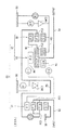
次に、上述した本実施形態の自動変速機を構成している各変速要素の具体的な構成及び配置について、図11から図14を参照して説明する。
本実施形態の自動変速機は、フロントエンジン・リヤドライブ(FR)車用の縦置き式トランスアクスルの形態をとっており、装置ケース50内に、入力軸52、第1中間回転軸56及び出力軸54が車両前後方向に延在して配置され、入力軸52が駆動源であるエンジン(図示せず)側の車両前方側に位置し、出力軸54が車両後方側に位置している。
【0037】
円筒形状の装置ケース50の内壁には、ケース内空間の後述する複数のクラッチや遊星ギヤを車両前方側のケース内空間Sf及び車両後方側のケース内空間Srとに画成するセンターサポート70が固定されている。
センターサポート70は、入力軸52及び第1中間回転軸56の軸心に対して直交する方向に装置ケース50の内壁から延在している環状の支持壁70aと、この支持壁70aの内径部から前記軸心と平行に車両後方側に延在している略円筒形状のボス部70bとを一体化した部材である。そして、ボス部70bの内周の車両前方側にはインナースリーブ71が嵌め込まれており、ブッシュ73を介して第2中間回転軸74を回転自在に支持している(図14参照)。また、この第2中間回転軸74の内周にブッシュ75が嵌合しており、このブッシュ75を介して第1中間回転軸56が回転自在に支持されている(図14参照)。
【0038】
減速遊星ギヤG1及び第3クラッチC3は、入力軸52の径方向外方位置である車両前方側のケース内空間Sfに配置されている。
第1ブレーキB1及び第1ワンウェイクラッチOWC1は、第1中間回転軸56の車両前方側端部の径方向外方側であるセンターサポート70近くの車両後方側のケース内空間Srに配置されている。また、第2クラッチC2は、第1中間回転軸56の車両後方側端部の径方向外方位置である車両後方側のケース内空間Srに配置されている。
【0039】
そして、第1及び第2変速遊星ギヤG2,G3,第1クラッチC1,第2及び第3ブレーキB2,B3及び第2ワンウェイクラッチOWC2は、出力軸54の径方向外方位置である車両後方側のケース内空間Srに配置されている。また、第2ブレーキB2は、他の変速要素に対して最も車両後方位置に配置されている。
【0040】
次に、各変速要素を、車両の前方側に配置した変速要素からさらに具体的に説明していくと、減速遊星ギヤG1は、減速キャリアPC1の内径側に形成した円筒部と入力軸52の外周とがスプライン結合されているとともに、減速リングギヤR1の内径側に形成した円筒部と第1中間回転軸56の外周とがスプライン結合されている。
【0041】
第3クラッチC3は、図12に示すように、減速遊星ギヤG1の外周に配置されており、減速遊星ギヤG1のキャリアPC1にスプライン結合したドラム72aと、このドラム72aの内周側に配置したクラッチハブ72bと、ドラム72a及びクラッチハブ72b間に交互に配置された摩擦板72c,72dと、ドラム72aの内周部に形成したシリンダ部に嵌め込んだピストン72eと、ピストン72eをシリンダ部側に押圧するリターンスプリング72fとを備えている。そして、減速遊星ギヤG1に対して車両前方側であってシリンダ部とピストン72eとの間に画成したシリンダ室72gに入力軸52の油路52a側からドラム油路72hを介して油圧の供給制御を行うことで、ピストン72eを軸方向に移動させて摩擦板72c,72dの締結・開放を行っている。
【0042】
センターサポート70の支持壁70aと減速遊星ギヤG1の減速リングギヤR1の壁部との間で平行に延在している前記クラッチハブ72bの壁部は、支持壁70a側及び減速リングギヤR1側に配置したスラストベアリングSBに回転自在に支持されている。そして、クラッチハブ72bの内径部は、センターサポート70のボス部70b内を通過している第2中間回転軸74の一端側外周にスプライン結合されている。この第2中間回転軸74の他端側は、変速遊星ギヤ列GT、第1クラッチ1及び第2クラッチ2を囲むように配置した胴長ドラム76の一端部に固定されている。
【0043】
そして、センターサポート70の支持壁70aには、装置ケース50側から油圧が供給されてくる油路70cと共に図示しない油路が複数形成されており、ボス部70bには、油路70cに連通する油路70dと共に、前記の複数の油路に連通する図示しない油路が形成されている。
また、図14に示すように、ボス部70bの内周側には、油路70dを含む複数の油路にそれぞれ連通する複数の油穴70e,70f,70gが形成されている。これらの油孔のうち、油孔70eは、第1ワンウェイクラッチOWC1と軸方向でオーバーラップした位置に設けられている。ボス部70bの内周に嵌め込まれているインナースリーブ71には、前記油穴70e,70f,70gにそれぞれ連通する複数の油穴71a,71b,71cが形成されている。そして、これらインナースリーブ71の複数の油穴71a,71b,71cに、第2中間回転軸74の径方向に形成した複数の油路74a,74b,74cが連通している。さらに、第1中間回転軸56には、内部に油路56aと共に図示しない油路が複数形成され、この油路56aと共に図示しない油路にそれぞれ連通する複数の油穴56d,56e,56fが径方向に形成されており、これら油穴56de,56fが、それぞれ前記第2中間回転軸74の油路74a,74b,74cに連通している。
【0044】
また、第2中間回転軸74の油路74b,74cの間には、各油路からリークした油をドレンする油路74dが形成されている。
第1ブレーキB1は、図12に示すように、センターサポート70の支持壁70aに形成したシリンダ部78aと、このシリンダ部78aに嵌め込んだピストン78bと、胴長ドラム76の外周に固定した第1ワンウェイクラッチOWC1のアウターレース79aと装置ケース50の内壁との間に交互に配置された摩擦板78c,78dと、ピストン78bをシリンダ部78a側に押圧するリターンスプリング78eとを備えている。そして、シリンダ部78aとピストン78bとの間に画成したシリンダ室78fに油路(図示せず)から油圧の供給制御を行うことで、ピストン78bを軸方向に移動させて摩擦板78c,78dの締結・開放の制御を行っている。
【0045】
第1ワンウェイクラッチOWC1は、第1ブレーキB1の径方向内方側に配置されており、前述したアウターレース79aと、センターサポート70のボス部70bの外周にスプライン結合されているインナーレース79bと、アウターレース79a及びインナーレース79bの間に所定間隔をあけて配置されているスプラグ等のコマ79cとを備えている。
【0046】
第2クラッチC2は、図13に示すように、胴長ドラム76の内径側に配置されて第1中間回転軸56の結合部56hで結合されている第1ドラム80と、この第1ドラム80の内径側に軸方向に摺動自在に嵌め込まれているシリンダ形成部材82aと、このシリンダ形成部材82aと接しながら第1ドラム80の外径側の内壁及び第1中間回転軸56の外周面上で軸方向に摺動自在に配置され、第1クラッチC1のピストンとして機能する第2ドラム82bと、第1変速遊星ギヤG2の第1サンギヤS2に固定したクラッチハブ82cと、第2ドラム82b及びクラッチハブ82c間に交互に配置された摩擦板82d,82eと、第1中間回転軸56の外周面上を長手方向に摺動可能に配置されたピストン82fと、ピストン82fをシリンダ部側に押圧するリターンスプリング82gとを備えている。そして、第2ドラム82b、ピストン82f及び第1中間回転軸56で画成したシリンダ室85cに、第1中間回転軸56の油路56aに連通している油穴85c1から油圧の供給制御を行うことで、ピストン82fを軸方向に移動させて摩擦板82d,82eの締結・開放の制御を行っている。
【0047】
第1クラッチC1は、第1ドラム80及び第1変速遊星ギヤG2の第1リングギヤR2間に交互に配置された摩擦板84a,84bと、前述した第1ドラム80、シリンダ形成部材82a、第2ドラム82b、リターンスプリング82gとを構成部材とし、第1ドラム80、シリンダ形成部材82a及び第1中間回転軸56とで画成したシリンダ室85a、シリンダ形成部材82a、第2ドラム82b及び第1中間回転軸56とで画成したシリンダ室85bとに、第1中間回転軸56の油路56aに連通している油穴85a1、85b1から油圧の供給制御を行うことで、ピストンとして機能するシリンダ形成部材82a及び第2ドラム82bを軸方向に移動させて摩擦板84a,84bの締結・開放の制御を行っている。
【0048】
ここで、図12では、第1クラッチC1のシリンダ室85a、シリンダ室85bと、第2クラッチC2のシリンダ室85cに通じる作動油の油路(センターサポート70の油路70c、70dからインナースリーブ71、第2中間回転軸74を介して第1中間回転軸56に通じる油路)を同一経路の油路として記載しているが、実際には、シリンダ室85a、シリンダ室85b及びシリンダ室85cのぞれぞれに対して専用の油路が設けられており、そのため、センターサポート70、インナースリーブ71、第2中間回転軸74及び第1中間回転軸56には、複数経路の作動油の油路が形成されている。
【0049】
図13に示すように、第1変速遊星ギヤG2には、第1キャリアPC2と一体回転するセンタプレート61が配置されているが、このセンタプレート61は、出力軸54にスプライン結合されている。
第2変速遊星ギヤG3は、第2リングギヤR3が第1変速遊星ギヤの第1キャリアPC2に固定され、第2キャリアPC3の車両後方側のキャリアプレートPC3Aが第1クラッチ1及び第2クラッチ2を囲っている胴長ドラム76の他端部に連結している。また、第2サンギヤS3は、第1変速遊星ギヤG2の第1サンギヤS2bとともに筒形状のサンギヤ一体部材58の外周に形成されており、このサンギヤ一体部材58は、出力軸54の外周にスプライン結合されている。
【0050】
第2ワンウェイクラッチOWC2は、前述したサンギヤ一体部材58にスプライン結合されているインナーレース87aと、アウターレース87bと、インナーレース87a及びインナーレース87bの間に所定間隔をあけて配置されているスプラグ等のコマ87cとを備えている。
第3ブレーキB3は、装置ケース50の内壁に形成したシリンダ部88aと、このシリンダ部88aに嵌め込んだ第3ブレーキ用ピストン88bと、装置ケース50の内壁及び第2ワンウェイクラッチOWC2のアウターレース87baの間に交互に配置された摩擦板88d,88eと、第3ブレーキ用ピストン88bをシリンダ部88a側に押圧するリターンスプリング88fとを備えている。そして、シリンダ部88aと第3ブレーキ用ピストン88bとの間に画成したシリンダ室88gに油路(図示せず)から油圧の供給制御を行うことで、第3ブレーキピストン88bを軸方向に移動させて摩擦板88d,88eの締結・開放の制御を行っている。
【0051】
第2ブレーキB2は、前述した第3ブレーキ用ピストン88bの内壁部をシリンダ部とし、このシリンダ部に嵌め込んだ第2ブレーキ用ピストン90aと、第2ワンウェイクラッチOWC2のインナーレース87aに固定されたブレーキハブ90bと、このブレーキハブ90b及び第3ブレーキ用ピストン88bの間に交互に配置された摩擦板90c,90dと、第3ブレーキ用ピストン90aをシリンダ部側に押圧する前述したリターンスプリング88aとで構成されており、シリンダ部と第2ブレーキ用ピストン90aとの間に画成したシリンダ室90eに油圧の供給制御を行うことで、第2ブレーキピストン90aを軸方向に移動させて摩擦板90c,90dの締結・開放の制御を行っている。
【0052】
さらに、図13に示すように、第2ブレーキB2の内径側に位置している出力軸54は、車両前方側に延在している装置ケース50の筒状部内に配置したブッシュ91を介して回転自在に支持されている。
ここで、図1のスケルトン図で示した回転メンバM1は、互いに連結している第1変速遊星ギヤG2の第1キャリアPC2と、第2変速遊星ギヤG3の第2リングギヤP3と、出力軸54とで構成されている。回転メンバM2は、第1変速遊星ギヤG2の第1サンギヤS2bと、第2変速遊星ギヤG3の第2サンギヤS3と、前述したサンギヤ一体部材58と、第2ワンウェイクラッチOWC2のインナレース87aと、第2ブレーキB2のブレーキハブ90bとで構成される。回転メンバM3は、第1変速遊星ギヤG2の第1サンギヤS2aと、第2クラッチC2のクラッチハブ82cとで構成されている。
【0053】
また、回転メンバM4は、減速回転経路を構成する回転メンバであり、減速遊星ギヤG1の減速リングギヤR1で構成されている。さらに、回転メンバM5は、非減速回転経路を構成する回転メンバであり、第2変速遊星ギヤG3の第2キャリアPC3と、他端側が第2変速遊星ギヤG3の第2キャリアPC3に固定されている胴長ドラム76と、第3クラッチC3のクラッチハブにスプライン結合している第2中間回転軸74と、第3クラッチC3のクラッチハブとで構成されている。
【0054】
次に、本実施形態の作用効果について述べる。
入力軸52側から減速遊星ギヤG1,第2クラッチC2,第1クラッチC1,変速遊星ギヤGTの順に配置したので、非減速回転経路に比べ強度が必要となる減速回転経路を短縮でき、軽量化を達成できる。これに加え、以下に列挙する効果を有する。
【0055】
第1クラッチC1及び第2クラッチC2は、減速遊星ギヤG1側から伝達されてきた減速回転を第1変速遊星ギヤG2に伝達する減速回転経路上に配置されているので、締結容量を大きくする必要がある。
本実施形態では、第1クラッチC1のピストンとして機能するシリンダ形成部材(以下、ピストンと称する)82a、第2ドラム(以下、ピストンと称する)82b、第2クラッチC2のピストン82fを、センターサポート70のボス部70bに対して軸方向にオフセットした位置に配置し、それらピストンの内径部が、第1中間回転軸56の外周で摺動自在に係合している。このように、ピストン82a,82b,82fの内径部がセンターサポート70のボス部70bに対して軸方向にオフセットした中間回転軸56の外周に係合していることから、ピストン82a,82b,82fの内径を小さくすることで、装置ケース50の外径寸法を大きくせずにピストン82a,82b,82fの受圧面積を増大させて締結容量を大きくすることができる。
【0056】
さらに、減速回転経路を構成する第1中間回転軸56を、非減速回転経路を構成する第2中間回転軸74の内周側に配置するようにしたため、ピストン82a,82b,82fの配置が第2中間回転軸74に規制されなくなり、第1中間回転軸56を小径の部材とすることでピストン82a,82b,82fの内径をさらに小径として受圧面積を十分に大きくすることができる。
【0057】
また、本実施形態では第1クラッチC1及び第2クラッチC2の締結容量を大きくするために作動油圧を高くする方法等を採用していないので、燃費の悪化を防止することができる。
また、装置ケース50の外径寸法が小さい本実施形態の自動変速機をFR車両に適用し、車両フロア下部のトンネルに搭載しても、トンネルの広さに関係なく容易に搭載できるので、FR車両用への搭載性が向上するという効果を得ることができる。
【0058】
さらに、第1中間回転軸56のなかで動力伝達に関与しない位置である、第1中間回転軸56の第1ドラム80との結合位置よりも車両後方側に、第1クラッチC1のシリンダ室85a,85b,第2クラッチC2のシリンダ室85cを形成したことによって、強度がそれほど必要とはならない位置にピストン82a,82b,82fを配置でき、ピストン82a,82b,82fの内径をさらに小径に設定できる。
【0059】
さらにまた、装置ケース50に固定されたセンターサポート70を、減速遊星ギヤG1と、第1クラッチC1のシリンダ室85a,85b,第2クラッチC2のシリンダ室85cとの間に設けたので、それらシリンダ室への作動油の油路70c等を設けることができるようになり、油路を短縮できるとともに、クラッチの作動油路のとりまわしも容易となる。また、センターサポート70の内径部のブッシュ73,75位置で、第1中間回転軸56と第2中間回転軸74を回転可能に支持するので、出力軸56,74の支持点を短縮することができ、ノイズの発生を抑制できる。
【0060】
なお、上記実施形態においては、自動変速機を前進6速を実現するギヤトレインを構成しているが、これに限定されるものではなく、前進5速以下又は7速以上の自動変速機にも本発明を適用することができる。
【0061】
【発明の効果】
以上説明したように、本発明の請求項1記載の自動変速機によると、前記減速遊星ギヤ、前記第1減速クラッチ及び第2減速クラッチの締結を行うピストンのシリンダ室、前記変速遊星ギヤの順で同軸に配置したので、非減速回転経路に比べ強度が必要となる減速回転経路を短縮でき、軽量化を達成できる。
【0062】
また、非減速回転経路の回転を伝達する非減速回転軸の内周側に、減速回転経路の回転を伝達する減速回転軸を配置し、大きな締結容量を必要とする第1及び第2減速クラッチのピストンを減速回転軸の外周面上に摺動可能に配置したことから、第1及び第2減速クラッチのピストンの内径の径が非減速回転軸の外径寸法に規制されなくなる。したがって、減速回転軸を小径とし、第1及び第2減速クラッチのピストンの内径を小さして受圧面積を大きくすることで、大きな締結容量の第1及び第2減速クラッチとすることができる。
【0063】
また、本発明は、第1及び第2減速クラッチの締結容量を大きくするために作動油圧を高くする方法等を採用していないので、燃費の悪化を防止することができる。
また、外径寸法が小さい本発明の自動変速機をFR車両に適用し、車両フロア下部のトンネルに搭載しても、トンネルの広さに関係なく容易に搭載できるので、FR車両用への搭載性が向上する。
【0064】
また、請求項1記載の発明によると、減速回転軸に第1及び第2減速クラッチの摩擦板が嵌合するドラムと結合する結合部を設け、第1及び第2減速クラッチのピストンを、減速回転軸の外周面上であって、且つ結合部よりも変速遊星ギヤ側の動力伝達に関与しない位置に摺動可能に配置したことから、強度がそれほど必要とはならない位置に第1及び第2減速クラッチのピストンを配置でき、それにより、ピストン内径の小径化を図って第1及び第2減速クラッチの締結容量を大きくすることができる。
【0065】
さらに、請求項2記載の発明によると、減速回転軸及び非減速回転軸を回転自在に支持するセンターサポートを、減速遊星ギヤと、第1減速クラッチ及び第2減速クラッチのシリンダ室との間に設け、シリンダ室へ作動油を供給する油路をセンターサポートに形成したことから、油路を短縮できるとともに、第1減速クラッチ及び第2減速クラッチの作動油路のとりまわしも容易となる。
【図面の簡単な説明】
【図1】本発明が適用された1実施形態の自動変速機を示すスケルトン図である。
【図2】本発明の1実施形態の自動変速機の締結表である。
【図3】本発明の1実施形態の自動変速機の共線図である。
【図4】本発明の1実施形態の自動変速機における前進1速のトルクフロー図である。
【図5】本発明の1実施形態の自動変速機における前進2速のトルクフロー図である。
【図6】本発明の1実施形態の自動変速機における前進3速のトルクフロー図である。
【図7】本発明の1実施形態の自動変速機における前進4速のトルクフロー図である。
【図8】本発明の1実施形態の自動変速機における前進5速のトルクフロー図である。
【図9】本発明の1実施形態の自動変速機における前進6速のトルクフロー図である。
【図10】本発明の1実施形態の自動変速機における後進1速のトルクフロー図である。
【図11】本発明の1実施形態の自動変速機を構成している各変速要素の具体的な構成及び配置を示す軸方向の半断面図である。
【図12】図11の軸方向の半断面図において入力軸側の一方側を具体的に示した図である。
【図13】図11の軸方向の半断面図において出力軸側の他方側を具体的に示した図である。
【図14】図11の軸方向の半断面図においてセンタサポートから第1中間回転軸に通じる油路を詳細に示した図である。
【図15】従来の自動変速機を示す軸方向の半断面概略図である。
【符号の説明】
52 入力軸
54 出力軸
56 第1中間回転軸(減速回転軸)
56a 第1中間回転軸に形成した油路
56d,56e,56f 第1中間回転軸に形成した油穴
70 センターサポート
70a 支持壁
70b ボス部
70c センターサポートの支持壁に形成した油路
70d センターサポートのボス部に形成した油路
70e,70f,70g ボス部に形成した油穴
71 インナースリーブ
71a,71b,71c インナースリーブに形成した油穴
74 第2中間回転軸(非減速回転軸)
74a,74b,74c 第2中間回転軸に形成した油路
80 第1ドラム(ドラム)
82a,82b,82f ピストン
85a,85b,85c クラッチのシリンダ室
85a1,85b1,85c1 中間回転軸に形成した油穴
C1 第1クラッチ(第1減速クラッチ)
C2 第2クラッチ(第2減速クラッチ)
C3 第3クラッチ(非減速クラッチ)
B1,B2,B3 ブレーキ
G1 減速遊星ギヤ
GT 変速遊星ギヤ列(変速遊星ギヤ)
G2 第1変速遊星ギヤ
G3 第2変速遊星ギヤ[0001]
BACKGROUND OF THE INVENTION
The present invention relates to an automatic transmission mounted on a vehicle, and more particularly, to a reduction clutch provided on a reduction / deceleration rotation path.
[0002]
[Prior art]
The automatic transmission includes a planetary gear set, and a clutch and a brake that change a power transmission path through the planetary gear set. There is a demand for multi-stage automatic transmissions in order to improve drivability and fuel consumption. In recent years, automatic transmissions that have achieved six forward speeds and one reverse speed have been put into practical use. .
[0003]
As an automatic transmission that achieves six forward speeds and one reverse speed, for example, there is a device (hereinafter referred to as a conventional automatic transmission) described in Japanese Patent Application Laid-Open No. 2000-120813 (FIG. 1 of this publication).
This conventional automatic transmission is in the form of a vertically mounted transaxle for a front engine / rear drive (FR) vehicle. As shown in FIG. 15, the engine (not shown) is connected to the input shaft 4. A reduction planetary gear (which is referred to as a reduction planetary gear in the publication) 6 that constantly reduces the transmitted rotational driving force, a reduced rotation from the reduced planetary gear 6 and a non-reduced rotation from the input shaft 4 side are input and output. A shifting planetary gear 10 (referred to as a planetary gear set in the publication) that is output to the
[0004]
Then, clutches C-1 and C that require a large engagement capacity disposed in a path (hereinafter referred to as a speed reduction rotation path) for outputting the reduction rotation transmitted from the reduction planetary gear 6 side to the transmission
[0005]
[Problems to be solved by the invention]
However, in the conventional automatic transmission described above, in the structure in which the two clutches C-1 and C-3 of the deceleration rotation path that require a large engagement capacity are arranged in parallel in the longitudinal direction, the fuel consumption and the automatic transmission are reduced. There is a problem in that the outer dimensions of the vehicle are increased in size and the vehicle mountability is deteriorated.
[0006]
That is, in order to increase the engagement capacity, the pressure receiving area of the
Therefore, for example, when the pressure receiving areas of the
[0007]
Further, in order to increase the fastening capacity, even if the number of friction plates of the clutches C-1 and C-3 is increased, the two clutches C-1 and C-3 are arranged in parallel in the longitudinal direction. Actually, it is difficult to increase the number of sheets, and further, if the operating hydraulic pressure is increased, problems such as deterioration of fuel consumption occur.
Accordingly, the present invention has been made in view of the above circumstances, and an object thereof is to provide an automatic transmission capable of achieving both weight reduction and improvement in vehicle mountability without deteriorating fuel consumption. .
[0008]
[Means for Solving the Problems]
In order to achieve the above object, an invention according to
[0009]
The invention according to
[0010]
DETAILED DESCRIPTION OF THE INVENTION
Hereinafter, an embodiment of an automatic transmission according to the present invention will be described with reference to the drawings.
FIG. 1 is a skeleton diagram showing an automatic transmission as one embodiment.
The automatic transmission according to this embodiment includes an
[0011]
The planetary gear set GS receives a double-pinion type reduction planetary gear G1 that constantly decelerates input rotation and a reduction rotation from the reduction planetary gear G1 or a non-deceleration rotation from the
[0012]
The reduction planetary gear G1 includes a reduction sun gear S1, a reduction ring gear R1 arranged concentrically with the reduction sun gear S1, a reduction pinion P1a meshing with the reduction sun gear S1, and the reduction pinion P1a and the reduction ring gear R1. This is a double-pinion type planetary gear provided with an intermeshing reduction pinion P1b and a reduction carrier PC1 that holds the reduction pinions P1a and P1b so as to rotate and revolve.
[0013]
The transmission planetary gear train GT is composed of two sets of first and second transmission planetary gears G2 and G3.
The first speed change planetary gear G2 includes a pair of first sun gears S2a, S2b having concentric and same outer diameters, a first ring gear R2 disposed concentrically with respect to the pair of first sun gears S2a, S2b, and a pair of first sun gears. 1 is a planetary gear provided with a first pinion P2 meshing between the sun gears S2a, S2b and the first ring gear R2, and a first carrier PC2 holding the first pinion P2 so as to rotate and revolve.
[0014]
The second speed change planetary gear G3 meshes between the second sun gear S3, the second ring gear R3 arranged concentrically with the second sun gear S3, and the second sun gear S3 and the second ring gear R3. The planetary gear includes a pinion P3 and a second carrier PC3 that holds the second pinion P3 so as to rotate and revolve.
On the other hand, the first clutch C1 is a clutch that selectively connects the reduction ring gear R1 of the reduction planetary gear G1 and the first ring gear R2 of the first transmission planetary gear G2. The second clutch C2 is a clutch that selectively connects the reduction ring gear R1 of the reduction planetary gear G1 and one of the pair of first sun gears S2a and S2b of the first transmission planetary gear G2. is there. The third clutch C3 is a clutch that selectively connects the reduction carrier PC1 of the reduction planetary gear G1 and the second carrier PC3 of the second transmission planetary gear G3.
[0015]
The first brake B1 is a brake that selectively stops the second carrier PC3 of the second speed change planetary gear G3. The second brake B2 is a brake that selectively stops the first sun gear S2b of the first speed change planetary gear G2 and the second sun gear S3 of the second speed change planetary gear G3. The third brake B3 is a brake that is arranged in parallel with the second brake B2 and selectively stops the second sun gear S2b of the first planetary gear G2 and the second sun gear S3 of the second shifting planetary gear G3. The third brake B3 is a device provided to avoid complicated hydraulic control of the engagement / release operation of the first brake B1 and the second brake B2 when shifting from the first forward speed to the second forward speed, which will be described later. .
[0016]
Further, the first one-way clutch OWC1 is a device that is arranged in parallel with the first brake B1 and that exerts the function of a brake by setting the engagement direction to the reaction torque support direction at the first forward speed described later. . The second one-way clutch OWC2 is arranged in series with the third brake B3, and is an apparatus that enhances the function of the second brake B2 by setting the engagement direction to the reaction torque support direction at the sixth forward speed described later. .
[0017]
Reference numerals M1, M2, M3, M4 and M5 are rotating members. The rotation member M1 is a member that rotates integrally with the first carrier PC2 of the first transmission planetary gear G2, the second ring gear R3 of the second transmission planetary gear G3, and the
The rotating member M2 is a member that is connected to the second brake B2 and is connected to one of the first sun gear S2b of the first shifting planetary gear G2 and the second sun gear S3 of the second shifting planetary gear G3 to rotate integrally. .
[0018]
The rotating member M3 is a member that is connected to the second clutch C2 and the first sun gear S2a of the first speed change planetary gear G2 and rotates integrally.
The rotating member M4 is a member that is connected to the first ring gear R2 of the first speed planetary gear G2 and the first clutch C1, and rotates integrally.
The rotating member M5 is a member that integrally rotates the third clutch C3 and the second carrier PC3 of the second speed planetary gear G3.
[0019]
The first to third clutches C1, C2, C3 and the first to third brakes B1, B2, B3 are connected to a transmission hydraulic pressure control device (not shown). As shown in the engagement operation table, the engagement and release (engaged with a circle, released with no mark, and engaged only when engine braking is performed with a triangle) are created at each gear stage. In addition, as a transmission hydraulic pressure control apparatus, a hydraulic control type, an electronic control type, a hydraulic pressure + electronic control type, etc. can be considered.
[0020]
Next, the operation of each shift stage of the automatic transmission according to the present embodiment will be described with reference to the alignment chart of FIG. 3 and the torque flows of FIGS. In FIGS. 4 to 10, the torque transmission path of the clutch / brake is indicated by hatching, and the path of the torque transmission member is indicated by a bold line.
(Forward 1st speed)
As shown in FIG. 2, the first forward speed (1st) is obtained by engaging the first clutch C1 and the first brake B1. Here, the first brake B1 is engaged when the engine is braked, and the first one-way clutch OWC1 functions as a brake when the engine is not braked.
[0021]
At the first forward speed, as shown in FIG. 4, the reduction sun gear S1 of the reduction planetary gear G1 is fixed to the
[0022]
On the other hand, in the second transmission planetary gear G3, the third carrier PC3 is fixed by the engagement of the first one-way clutch OWC1, and the reduced rotation of the first sun gear S2b of the first transmission planetary gear G2 is input to the second sun gear S3. The rotation further reduced from the second ring gear R3, which is the rotation member M1, is output to the first carrier PC2 of the first transmission planetary gear G2.
[0023]
Therefore, in the first speed change planetary gear G2, the slowest speed reduction rotation is transmitted from the first carrier PC2 to the
Therefore, at the first forward speed, as shown in the collinear diagram of FIG. 3, the first clutch C1 is engaged with the reduced rotation from the reduction planetary gear G1 as the input rotation to the first ring gear R2 of the first transmission planetary gear G2. The rotation input from the
[0024]
(2nd forward speed)
As shown in FIG. 2, the second forward speed (2nd) is obtained by engaging the first clutch C1, the second brake B2, or the third brake B3 and the second one-way clutch OWC2.
In the second forward speed, as shown in FIG. 5, when the first clutch C1 is engaged, the reduction rotation in the positive direction is input from the reduction planetary gear G1 to the first ring gear R2 of the first transmission planetary gear G2, which is the rotation member M4. The Since the first sun gear S2b of the first transmission planetary gear G2, which is the rotating member M2, is fixed to the
[0025]
Therefore, in the first speed planetary gear G2, rotation faster than the first forward speed is transmitted from the first carrier PC2 to the
Therefore, at the second forward speed, as shown in the collinear diagram of FIG. 3, the engagement of the first clutch C1 with the reduced rotation from the reduction planetary gear G1 as the input rotation to the first ring gear R2 of the first transmission planetary gear G2 is engaged. Is defined by a line connecting the point and the engagement point of the second brake B2 that stops the rotation of the first sun gear S2b of the first speed planetary gear G2, and the decelerated rotation input from the
[0026]
(Forward 3rd speed)
The third forward speed (3rd) is obtained by engaging the first clutch C1 and the second clutch C2, as shown in FIG.
In the third forward speed, as shown in FIG. 6, when the first clutch C1 is engaged, the forward reduction rotation from the reduction planetary gear G1 is input to the first ring gear R2 of the first transmission planetary gear G2, which is the rotation member M4. Then, it is transmitted from the first carrier PC2, which is the rotating member M1, to the
[0027]
Therefore, at the third forward speed, as shown in the collinear diagram of FIG. 3, the first clutch C1 is engaged with the reduced rotation from the reduction planetary gear G1 as the input rotation to the first ring gear R2 of the first transmission planetary gear G2. Is defined by a line connecting the point and the engagement point of the second clutch C2 which makes the reduced rotation from the first planetary gear G1 the input rotation to the first sun gear S2a of the first variable planetary gear G2. The input decelerated rotation is decelerated and output to the
[0028]
(Forward 4th speed)
As shown in FIG. 2, the fourth forward speed (4th) is obtained by engaging the first clutch C1 and the third clutch C3.
In this forward fourth speed, as shown in FIG. 7, when the first clutch C1 is engaged, the reduction rotation in the positive direction from the reduction planetary gear G1 is input to the first ring gear R2 of the first transmission planetary gear G2, which is the rotation member M4. Is done. Further, by the engagement of the third clutch C3, the rotation of the
[0029]
For this reason, the first speed change planetary gear G2 receives the reduced speed rotation input to the first carrier PC2, and the rotation speed-up from the first ring gear R2 is increased (lower than the input speed). It is transmitted from one carrier PC2 to the
Therefore, at the fourth forward speed, as shown in the collinear diagram of FIG. 3, the first clutch C1 is engaged with the reduced rotation from the reduction planetary gear G1 as the input rotation to the first ring gear R2 of the first transmission planetary gear G2. The rotation input from the
[0030]
(5th forward)
As shown in FIG. 2, the fifth forward speed (5th) is obtained by engaging the second clutch C2 and the third clutch C3.
In this forward fifth speed, as shown in FIG. 8, when the second clutch C2 is engaged, the forward reduced rotation from the reduced planetary gear G1 is input to the first sun gear S2a of the first variable planetary gear G2, which is the rotating member M3. Is done. Further, by the engagement of the third clutch C3, the rotation of the
[0031]
For this reason, the first speed change planetary gear G2 receives the rotation speed increased from the rotation speed of the
Therefore, at the fifth forward speed, as shown in the collinear diagram of FIG. 3, the second clutch C2 uses the reduced rotation from the first planetary gear G1 as the input rotation to the first sun gear S2a of the first variable planetary gear G2. Specified by a line connecting the engagement point and the engagement point of the third clutch C3 that inputs the rotation of the
[0032]
(6 forward speed)
As shown in FIG. 2, the sixth forward speed (6th) is obtained by engaging the third clutch C3 and the second brake B2.
At the sixth forward speed, as shown in FIG. 9, the rotation of the
[0033]
For this reason, the second transmission planetary gear G3 has the second sun gear S3 fixed, so that the rotation input to the second carrier PC3 is the first member of the second ring gear R3 and the first transmission planetary gear G2 whose rotation member M1 is the rotation. The speed is increased and transmitted to the carrier PC2.
Therefore, at the sixth forward speed, as shown in the collinear diagram of FIG. 3, the engagement point of the third clutch C3 for inputting the rotation of the
[0034]
(Reverse 1st speed)
The first reverse speed (Rev) is obtained by engaging the second clutch C2 and the first brake B1, as shown in FIG.
At the first reverse speed, the reduced rotation from the reduction planetary gear G1 is input to the first sun gear S2a of the first transmission planetary gear G2 by the engagement of the second clutch C1. Further, the second carrier PC3 of the second speed planetary gear G3 is fixed to the
[0035]
Therefore, in the first transmission planetary gear G2, the reaction force of the first sun gear S2a is taken by the second carrier PC3 fixed by the engagement of the first brake B1, and the reverse rotation of the first sun gear S2a is the rotating member. M1 is transmitted to the first carrier PC2 and the
Therefore, at the first reverse speed, as shown in the collinear diagram of FIG. 3, the second clutch C2 uses the reduced rotation from the first planetary gear G1 as the input rotation to the first sun gear S2a of the first variable planetary gear G2. It is defined by a line connecting the engagement point and the engagement point of the first brake B1 that stops the rotation of the second carrier PC3 of the second speed planetary gear G3, and the rotation input from the
[0036]
Next, a specific configuration and arrangement of each shift element constituting the automatic transmission of the present embodiment described above will be described with reference to FIGS.
The automatic transmission according to the present embodiment is in the form of a vertically mounted transaxle for a front engine / rear drive (FR) vehicle. In the
[0037]
On the inner wall of the
The
[0038]
The reduction planetary gear G1 and the third clutch C3 are disposed in a case inner space Sf on the vehicle front side, which is a radially outward position of the
The first brake B1 and the first one-way clutch OWC1 are disposed in a case inner space Sr on the vehicle rear side near the
[0039]
The first and second shifting planetary gears G2 and G3, the first clutch C1, the second and third brakes B2 and B3, and the second one-way clutch OWC2 are on the vehicle rear side, which is the radially outward position of the
[0040]
Next, the speed change elements will be described more specifically from the speed change elements arranged on the front side of the vehicle. The reduction planetary gear G1 includes a cylindrical portion formed on the inner diameter side of the speed reduction carrier PC1 and the
[0041]
As shown in FIG. 12, the third clutch C3 is disposed on the outer periphery of the reduction planetary gear G1, and is arranged on the inner periphery side of the
[0042]
The wall portion of the
[0043]
A plurality of oil passages (not shown) are formed on the
As shown in FIG. 14, a plurality of
[0044]
Further, an
As shown in FIG. 12, the first brake B1 includes a
[0045]
The first one-way clutch OWC1 is arranged on the radially inner side of the first brake B1, and the
[0046]
As shown in FIG. 13, the second clutch C <b> 2 is disposed on the inner diameter side of the
[0047]
The first clutch C1 includes the
[0048]
Here, in FIG. 12, hydraulic oil passages (from the
[0049]
As shown in FIG. 13, a
In the second transmission planetary gear G3, the second ring gear R3 is fixed to the first carrier PC2 of the first transmission planetary gear, and the carrier plate PC3A on the vehicle rear side of the second carrier PC3 connects the
[0050]
The second one-way clutch OWC2 includes an inner race 87a splined to the sun gear integrated
The third brake B3 includes a
[0051]
The second brake B2 is fixed to the
[0052]
Further, as shown in FIG. 13, the
Here, the rotating member M1 shown in the skeleton diagram of FIG. 1 includes the first carrier PC2 of the first speed change planetary gear G2, the second ring gear P3 of the second speed change planetary gear G3, and the
[0053]
The rotating member M4 is a rotating member that constitutes a reduction rotation path, and is constituted by a reduction ring gear R1 of the reduction planetary gear G1. Further, the rotating member M5 is a rotating member that constitutes a non-decelerated rotating path, and the other end side is fixed to the second carrier PC3 of the second shifting planetary gear G3 and the other end side is fixed to the second carrier PC3 of the second shifting planetary gear G3. And a second intermediate rotating
[0054]
Next, the function and effect of this embodiment will be described.
Since the reduction planetary gear G1, the second clutch C2, the first clutch C1, and the transmission planetary gear GT are arranged in this order from the
[0055]
Since the first clutch C1 and the second clutch C2 are arranged on the reduction rotation path for transmitting the reduced rotation transmitted from the reduction planetary gear G1 side to the first transmission planetary gear G2, it is necessary to increase the engagement capacity. There is.
In this embodiment, a cylinder forming member (hereinafter referred to as a piston) 82a that functions as a piston of the first clutch C1, a second drum (hereinafter referred to as a piston) 82b, and a
[0056]
Further, since the first
[0057]
Further, in the present embodiment, since a method of increasing the hydraulic pressure is not employed in order to increase the engagement capacity of the first clutch C1 and the second clutch C2, it is possible to prevent deterioration in fuel consumption.
Further, even if the automatic transmission according to the present embodiment in which the outer diameter of the
[0058]
Further, the
[0059]
Furthermore, since the
[0060]
In the above-described embodiment, the automatic transmission is configured as a gear train that realizes the sixth forward speed. However, the present invention is not limited to this, and the automatic transmission may be an automatic transmission that is less than or equal to the fifth forward speed or the seventh speed. The present invention can be applied.
[0061]
【The invention's effect】
As described above, according to the automatic transmission of the first aspect of the present invention, the reduction planetary gear, the cylinder chamber of the piston that engages the first reduction clutch and the second reduction clutch, and the order of the transmission planetary gear. Therefore, it is possible to shorten the speed reduction rotation path that requires strength compared to the non-deceleration rotation path and to achieve weight reduction.
[0062]
First and second reduction clutches that require a large fastening capacity by disposing a reduction rotation shaft that transmits rotation of the deceleration rotation path on the inner peripheral side of the non-deceleration rotation shaft that transmits rotation of the non-deceleration rotation path. Since the pistons of the first and second reduction clutches are slidably disposed on the outer peripheral surface of the reduction rotating shaft, the inner diameters of the pistons of the first and second reduction clutches are not restricted by the outer diameter of the non-reducing rotating shaft. Therefore, the first and second reduction clutches having a large engagement capacity can be obtained by reducing the diameter of the reduction rotation shaft and decreasing the inner diameters of the pistons of the first and second reduction clutches to increase the pressure receiving area.
[0063]
In addition, since the present invention does not employ a method of increasing the hydraulic pressure in order to increase the engagement capacity of the first and second reduction clutches, it is possible to prevent deterioration of fuel consumption.
Even if the automatic transmission of the present invention having a small outer diameter is applied to an FR vehicle and mounted on a tunnel at the lower part of the vehicle floor, it can be easily mounted regardless of the size of the tunnel. Improves.
[0064]
Also,Claim 1According to the described invention,A coupling portion coupled to a drum to which the friction plates of the first and second reduction clutches are fitted to the reduction rotation shaft; and the pistons of the first and second reduction clutches on the outer peripheral surface of the reduction rotation shaft; Arranged to be slidable at a position not involved in power transmission on the shifting planetary gear side from the coupling partTherefore, the pistons of the first and second reduction clutches can be arranged at positions where the strength is not so required, thereby reducing the piston inner diameter and increasing the fastening capacity of the first and second reduction clutches. Can do.
[0065]
further,Claim 2According to the described invention, the center support that rotatably supports the reduction rotation shaft and the non-reduction rotation shaft is provided between the reduction planetary gear and the cylinder chambers of the first reduction clutch and the second reduction clutch, to the cylinder chamber. Since the oil passage for supplying the hydraulic oil is formed in the center support, the oil passage can be shortened and the hydraulic oil passages of the first reduction clutch and the second reduction clutch can be easily rotated.
[Brief description of the drawings]
FIG. 1 is a skeleton diagram showing an automatic transmission according to an embodiment to which the present invention is applied.
FIG. 2 is a fastening table of an automatic transmission according to an embodiment of the present invention.
FIG. 3 is a collinear diagram of the automatic transmission according to the embodiment of the present invention.
FIG. 4 is a torque flow diagram of the first forward speed in the automatic transmission according to the embodiment of the present invention.
FIG. 5 is a torque flow diagram of the second forward speed in the automatic transmission according to the embodiment of the present invention.
FIG. 6 is a torque flow diagram of the third forward speed in the automatic transmission according to the embodiment of the present invention.
FIG. 7 is a torque flow diagram of the fourth forward speed in the automatic transmission according to the embodiment of the present invention.
FIG. 8 is a torque flow diagram of the fifth forward speed in the automatic transmission according to the embodiment of the present invention.
FIG. 9 is a torque flow diagram at the sixth forward speed in the automatic transmission according to the embodiment of the present invention.
FIG. 10 is a torque flow diagram of the first reverse speed in the automatic transmission according to the embodiment of the present invention.
FIG. 11 is a half sectional view in the axial direction showing a specific configuration and arrangement of each speed change element constituting the automatic transmission according to the embodiment of the present invention.
12 is a diagram specifically showing one side on the input shaft side in the semi-sectional view in the axial direction of FIG. 11. FIG.
13 is a view specifically showing the other side on the output shaft side in the half sectional view in the axial direction of FIG. 11. FIG.
14 is a diagram showing in detail an oil passage that leads from the center support to the first intermediate rotation shaft in the half sectional view in the axial direction of FIG. 11;
FIG. 15 is a schematic half sectional view in the axial direction showing a conventional automatic transmission.
[Explanation of symbols]
52 Input shaft
54 Output shaft
56 First intermediate rotation axis (deceleration rotation axis)
56a Oil passage formed in the first intermediate rotation shaft
56d, 56e, 56f Oil hole formed in the first intermediate rotation shaft
70 Center support
70a Support wall
70b Boss
70c Oil passage formed in the support wall of the center support
70d Oil channel formed in the boss part of the center support
70e, 70f, 70g Oil hole formed in boss
71 Inner sleeve
71a, 71b, 71c Oil holes formed in the inner sleeve
74 Second intermediate rotating shaft (non-reducing rotating shaft)
74a, 74b, 74c Oil passage formed in the second intermediate rotation shaft
80 1st drum (drum)
82a, 82b, 82f Piston
85a, 85b, 85c Clutch cylinder chamber
85a1, 85b1, 85c1 Oil hole formed in the intermediate rotating shaft
C1 first clutch (first reduction clutch)
C2 Second clutch (second deceleration clutch)
C3 3rd clutch (non-deceleration clutch)
B1, B2, B3 Brake
G1 Reduction planetary gear
GT Variable planetary gear train (variable planetary gear)
G2 first speed planetary gear
G3 2nd planetary gear
Claims (2)
前記非減速回転経路の回転を伝達する非減速回転軸の内周側に、前記減速回転経路の回転を伝達する減速回転軸を配置し、
前記減速回転軸に前記第1及び第2減速クラッチの摩擦板が嵌合するドラムと結合する結合部を設け、
前記第1及び第2減速クラッチの前記ピストンを、前記減速回転軸の外周面上であって、且つ前記結合部よりも前記変速遊星ギヤ側の動力伝達に関与しない位置に摺動可能に配置したことを特徴とする自動変速機。An input shaft arranged on one side, a reduction planetary gear that constantly reduces the rotation of the input shaft, a reduced rotation from the reduced planetary gear side, and a non-reduced rotation from the input shaft side are input and the other side output and shifting the planetary gear to be outputted to the axis, a first reduction clutch and the second speed reduction clutch provided to the deceleration rotation on the path from the reduction planetary gear, non-reduction clutch provided on the non-reduced rotation path from the input shaft side An automatic transmission that is coaxially arranged in the order of the reduction planetary gear, a cylinder chamber of a piston that engages the first reduction clutch and the second reduction clutch, and the transmission planetary gear,
A reduction rotation shaft that transmits the rotation of the deceleration rotation path is disposed on the inner peripheral side of the non-deceleration rotation shaft that transmits the rotation of the non-deceleration rotation path,
A coupling portion coupled to a drum with which the friction plates of the first and second deceleration clutches are fitted to the reduction rotation shaft;
The pistons of the first and second reduction clutches are slidably disposed on the outer peripheral surface of the reduction rotation shaft and at positions that are not involved in power transmission on the speed-change planetary gear side with respect to the coupling portion. An automatic transmission characterized by that.
Priority Applications (1)
| Application Number | Priority Date | Filing Date | Title |
|---|---|---|---|
| JP2002229029A JP3746742B2 (en) | 2002-08-06 | 2002-08-06 | Automatic transmission |
Applications Claiming Priority (1)
| Application Number | Priority Date | Filing Date | Title |
|---|---|---|---|
| JP2002229029A JP3746742B2 (en) | 2002-08-06 | 2002-08-06 | Automatic transmission |
Publications (2)
| Publication Number | Publication Date |
|---|---|
| JP2004068917A JP2004068917A (en) | 2004-03-04 |
| JP3746742B2 true JP3746742B2 (en) | 2006-02-15 |
Family
ID=32015564
Family Applications (1)
| Application Number | Title | Priority Date | Filing Date |
|---|---|---|---|
| JP2002229029A Expired - Fee Related JP3746742B2 (en) | 2002-08-06 | 2002-08-06 | Automatic transmission |
Country Status (1)
| Country | Link |
|---|---|
| JP (1) | JP3746742B2 (en) |
Families Citing this family (2)
| Publication number | Priority date | Publication date | Assignee | Title |
|---|---|---|---|---|
| JP5460571B2 (en) * | 2010-12-22 | 2014-04-02 | ジヤトコ株式会社 | Automatic transmission |
| JP2015022940A (en) | 2013-07-19 | 2015-02-02 | 東京エレクトロン株式会社 | Plasma processing apparatus, abnormal oscillation determination method, and high-frequency generator |
-
2002
- 2002-08-06 JP JP2002229029A patent/JP3746742B2/en not_active Expired - Fee Related
Also Published As
| Publication number | Publication date |
|---|---|
| JP2004068917A (en) | 2004-03-04 |
Similar Documents
| Publication | Publication Date | Title |
|---|---|---|
| EP0997663B1 (en) | Vehicular automatic transmission | |
| US6887178B2 (en) | Automatic transmission | |
| JP4144106B2 (en) | Automatic transmission for vehicles | |
| US7052433B2 (en) | Automatic transmission | |
| JP2000220705A (en) | Automatic transmission for vehicle | |
| CN101375085B (en) | Automatic transmission | |
| US7955213B2 (en) | Automatic transmission | |
| JP3906578B2 (en) | Automatic transmission for vehicles | |
| US20030083172A1 (en) | Automatic transmission | |
| JP3751916B2 (en) | Gear transmission for automatic transmission | |
| JP3909622B2 (en) | Automatic transmission for vehicles | |
| JP3746742B2 (en) | Automatic transmission | |
| JP4083498B2 (en) | Automatic transmission | |
| JP4230728B2 (en) | Hydraulic oil passage structure of friction element for automatic transmission | |
| JP2004068918A (en) | Automatic transmission | |
| JP4081888B2 (en) | Automatic transmission | |
| JP3786905B2 (en) | Automatic transmission | |
| JP4161444B2 (en) | Automatic transmission | |
| US7628723B2 (en) | Multi-stage automatic gearbox | |
| JP3906576B2 (en) | Automatic transmission for vehicles | |
| JP2000136854A (en) | Automatic transmission for vehicle | |
| JP3831334B2 (en) | Gear transmission for automatic transmission | |
| JP3817919B2 (en) | Automatic transmission for vehicles | |
| JP2004068915A (en) | Automatic transmission | |
| JP4424426B2 (en) | Automatic transmission for vehicles |
Legal Events
| Date | Code | Title | Description |
|---|---|---|---|
| A621 | Written request for application examination |
Free format text: JAPANESE INTERMEDIATE CODE: A621 Effective date: 20040819 |
|
| A977 | Report on retrieval |
Free format text: JAPANESE INTERMEDIATE CODE: A971007 Effective date: 20050815 |
|
| A131 | Notification of reasons for refusal |
Free format text: JAPANESE INTERMEDIATE CODE: A131 Effective date: 20050823 |
|
| A521 | Written amendment |
Free format text: JAPANESE INTERMEDIATE CODE: A523 Effective date: 20051024 |
|
| TRDD | Decision of grant or rejection written | ||
| A01 | Written decision to grant a patent or to grant a registration (utility model) |
Free format text: JAPANESE INTERMEDIATE CODE: A01 Effective date: 20051115 |
|
| A61 | First payment of annual fees (during grant procedure) |
Free format text: JAPANESE INTERMEDIATE CODE: A61 Effective date: 20051124 |
|
| R150 | Certificate of patent or registration of utility model |
Free format text: JAPANESE INTERMEDIATE CODE: R150 |
|
| FPAY | Renewal fee payment (event date is renewal date of database) |
Free format text: PAYMENT UNTIL: 20081202 Year of fee payment: 3 |
|
| FPAY | Renewal fee payment (event date is renewal date of database) |
Free format text: PAYMENT UNTIL: 20091202 Year of fee payment: 4 |
|
| FPAY | Renewal fee payment (event date is renewal date of database) |
Free format text: PAYMENT UNTIL: 20091202 Year of fee payment: 4 |
|
| FPAY | Renewal fee payment (event date is renewal date of database) |
Free format text: PAYMENT UNTIL: 20101202 Year of fee payment: 5 |
|
| FPAY | Renewal fee payment (event date is renewal date of database) |
Free format text: PAYMENT UNTIL: 20101202 Year of fee payment: 5 |
|
| FPAY | Renewal fee payment (event date is renewal date of database) |
Free format text: PAYMENT UNTIL: 20111202 Year of fee payment: 6 |
|
| FPAY | Renewal fee payment (event date is renewal date of database) |
Free format text: PAYMENT UNTIL: 20111202 Year of fee payment: 6 |
|
| FPAY | Renewal fee payment (event date is renewal date of database) |
Free format text: PAYMENT UNTIL: 20121202 Year of fee payment: 7 |
|
| FPAY | Renewal fee payment (event date is renewal date of database) |
Free format text: PAYMENT UNTIL: 20121202 Year of fee payment: 7 |
|
| FPAY | Renewal fee payment (event date is renewal date of database) |
Free format text: PAYMENT UNTIL: 20131202 Year of fee payment: 8 |
|
| FPAY | Renewal fee payment (event date is renewal date of database) |
Free format text: PAYMENT UNTIL: 20131202 Year of fee payment: 8 |
|
| FPAY | Renewal fee payment (event date is renewal date of database) |
Free format text: PAYMENT UNTIL: 20141202 Year of fee payment: 9 |
|
| LAPS | Cancellation because of no payment of annual fees |