JP3745602B2 - Body set type speaker device - Google Patents
Body set type speaker device Download PDFInfo
- Publication number
- JP3745602B2 JP3745602B2 JP2000226413A JP2000226413A JP3745602B2 JP 3745602 B2 JP3745602 B2 JP 3745602B2 JP 2000226413 A JP2000226413 A JP 2000226413A JP 2000226413 A JP2000226413 A JP 2000226413A JP 3745602 B2 JP3745602 B2 JP 3745602B2
- Authority
- JP
- Japan
- Prior art keywords
- speaker
- user
- directional
- sound
- set type
- Prior art date
- Legal status (The legal status is an assumption and is not a legal conclusion. Google has not performed a legal analysis and makes no representation as to the accuracy of the status listed.)
- Expired - Fee Related
Links
- 210000000988 bone and bone Anatomy 0.000 claims description 23
- 210000000613 ear canal Anatomy 0.000 claims description 16
- 210000003128 head Anatomy 0.000 claims description 9
- 210000005069 ears Anatomy 0.000 claims description 8
- 230000005236 sound signal Effects 0.000 claims description 4
- 230000006835 compression Effects 0.000 description 4
- 238000007906 compression Methods 0.000 description 4
- 230000037237 body shape Effects 0.000 description 3
- 238000010586 diagram Methods 0.000 description 3
- 210000000481 breast Anatomy 0.000 description 2
- 210000003054 facial bone Anatomy 0.000 description 2
- 239000011521 glass Substances 0.000 description 2
- 230000003287 optical effect Effects 0.000 description 2
- 230000002093 peripheral effect Effects 0.000 description 2
- 125000002066 L-histidyl group Chemical group [H]N1C([H])=NC(C([H])([H])[C@](C(=O)[*])([H])N([H])[H])=C1[H] 0.000 description 1
- 230000009286 beneficial effect Effects 0.000 description 1
- 230000015572 biosynthetic process Effects 0.000 description 1
- 210000000038 chest Anatomy 0.000 description 1
- 210000000860 cochlear nerve Anatomy 0.000 description 1
- 238000010276 construction Methods 0.000 description 1
- 239000004744 fabric Substances 0.000 description 1
- 125000006850 spacer group Chemical group 0.000 description 1
Images


Classifications
-
- A—HUMAN NECESSITIES
- A42—HEADWEAR
- A42B—HATS; HEAD COVERINGS
- A42B1/00—Hats; Caps; Hoods
- A42B1/24—Hats; Caps; Hoods with means for attaching articles thereto, e.g. memorandum tablets or mirrors
- A42B1/245—Means for mounting audio or communication systems
-
- A—HUMAN NECESSITIES
- A42—HEADWEAR
- A42B—HATS; HEAD COVERINGS
- A42B3/00—Helmets; Helmet covers ; Other protective head coverings
- A42B3/04—Parts, details or accessories of helmets
- A42B3/30—Mounting radio sets or communication systems
-
- H—ELECTRICITY
- H04—ELECTRIC COMMUNICATION TECHNIQUE
- H04M—TELEPHONIC COMMUNICATION
- H04M1/00—Substation equipment, e.g. for use by subscribers
- H04M1/02—Constructional features of telephone sets
- H04M1/04—Supports for telephone transmitters or receivers
- H04M1/05—Supports for telephone transmitters or receivers specially adapted for use on head, throat or breast
-
- H—ELECTRICITY
- H04—ELECTRIC COMMUNICATION TECHNIQUE
- H04M—TELEPHONIC COMMUNICATION
- H04M1/00—Substation equipment, e.g. for use by subscribers
- H04M1/60—Substation equipment, e.g. for use by subscribers including speech amplifiers
- H04M1/6033—Substation equipment, e.g. for use by subscribers including speech amplifiers for providing handsfree use or a loudspeaker mode in telephone sets
- H04M1/6041—Portable telephones adapted for handsfree use
- H04M1/6058—Portable telephones adapted for handsfree use involving the use of a headset accessory device connected to the portable telephone
-
- H—ELECTRICITY
- H04—ELECTRIC COMMUNICATION TECHNIQUE
- H04R—LOUDSPEAKERS, MICROPHONES, GRAMOPHONE PICK-UPS OR LIKE ACOUSTIC ELECTROMECHANICAL TRANSDUCERS; DEAF-AID SETS; PUBLIC ADDRESS SYSTEMS
- H04R1/00—Details of transducers, loudspeakers or microphones
- H04R1/08—Mouthpieces; Microphones; Attachments therefor
- H04R1/083—Special constructions of mouthpieces
-
- H—ELECTRICITY
- H04—ELECTRIC COMMUNICATION TECHNIQUE
- H04R—LOUDSPEAKERS, MICROPHONES, GRAMOPHONE PICK-UPS OR LIKE ACOUSTIC ELECTROMECHANICAL TRANSDUCERS; DEAF-AID SETS; PUBLIC ADDRESS SYSTEMS
- H04R1/00—Details of transducers, loudspeakers or microphones
- H04R1/10—Earpieces; Attachments therefor ; Earphones; Monophonic headphones
- H04R1/1058—Manufacture or assembly
- H04R1/1066—Constructional aspects of the interconnection between earpiece and earpiece support
-
- H—ELECTRICITY
- H04—ELECTRIC COMMUNICATION TECHNIQUE
- H04R—LOUDSPEAKERS, MICROPHONES, GRAMOPHONE PICK-UPS OR LIKE ACOUSTIC ELECTROMECHANICAL TRANSDUCERS; DEAF-AID SETS; PUBLIC ADDRESS SYSTEMS
- H04R2201/00—Details of transducers, loudspeakers or microphones covered by H04R1/00 but not provided for in any of its subgroups
- H04R2201/10—Details of earpieces, attachments therefor, earphones or monophonic headphones covered by H04R1/10 but not provided for in any of its subgroups
- H04R2201/107—Monophonic and stereophonic headphones with microphone for two-way hands free communication
-
- H—ELECTRICITY
- H04—ELECTRIC COMMUNICATION TECHNIQUE
- H04R—LOUDSPEAKERS, MICROPHONES, GRAMOPHONE PICK-UPS OR LIKE ACOUSTIC ELECTROMECHANICAL TRANSDUCERS; DEAF-AID SETS; PUBLIC ADDRESS SYSTEMS
- H04R2460/00—Details of hearing devices, i.e. of ear- or headphones covered by H04R1/10 or H04R5/033 but not provided for in any of their subgroups, or of hearing aids covered by H04R25/00 but not provided for in any of its subgroups
- H04R2460/13—Hearing devices using bone conduction transducers
-
- H—ELECTRICITY
- H04—ELECTRIC COMMUNICATION TECHNIQUE
- H04R—LOUDSPEAKERS, MICROPHONES, GRAMOPHONE PICK-UPS OR LIKE ACOUSTIC ELECTROMECHANICAL TRANSDUCERS; DEAF-AID SETS; PUBLIC ADDRESS SYSTEMS
- H04R5/00—Stereophonic arrangements
- H04R5/033—Headphones for stereophonic communication
- H04R5/0335—Earpiece support, e.g. headbands or neckrests
Landscapes
- Engineering & Computer Science (AREA)
- Signal Processing (AREA)
- Physics & Mathematics (AREA)
- Acoustics & Sound (AREA)
- Health & Medical Sciences (AREA)
- Otolaryngology (AREA)
- Manufacturing & Machinery (AREA)
- Telephone Set Structure (AREA)
- Details Of Audible-Bandwidth Transducers (AREA)
- Obtaining Desirable Characteristics In Audible-Bandwidth Transducers (AREA)
Description
【0001】
【発明の属する技術分野】
本発明は、例えばオーディオ機器の再生音や通信機器の音声等を出力する身体セット型スピーカ装置に係り、詳しくは外界音の聞き取りを確保しつつスピーカ音を聞くことのできる身体セット型スピーカ装置に関するものである。
【0002】
【従来の技術】
オーディオ機器、パソコン、通信機器等からの音を聞く機器として、イヤホーン及びヘッドホーンがある。また、内蔵スピーカ付き小型ラジオをワイシャツ等の胸ポケットに入れて、胸ポケット内の内蔵スピーカからのラジオ放送の音を聞いている人は時折、目にするところである。
【0003】
【発明が解決しようとする課題】
イヤホーンやヘッドホーンでは、耳が外界に対して塞がれてしまうため、ユーザは、外界音は聞けず、スピーカ音のみを聞くことになる。胸ポケット等、耳の周囲に配備したスピーカから音を聞く場合では、外界音の聞き取りは確保されるが、周囲へスピーカ音を撒き散らし、他人に迷惑を掛ける。
【0004】
なお、特開平8−33079号公報のイヤホーンでは、ミニチュアスピーカに弾性的なパッドカバーを被せ、パッドカバーを耳穴に挿入することにより、パッドカバーはスペーサの役割を担い、スピーカ面は耳穴から所定距離、離れて保持されるようになっている。しかしながら、このイヤホーンでは、スピーカ面と耳穴との間の空間は、パッドカバーにより外界に対して閉鎖され、外界音は耳穴へ到達するのを抑制されている。
【0005】
また、イヤホーンを片耳のみに装着して、別の片耳は開放して、外界音を聞くことがあるが、両耳でそれぞれスピーカ音及び外界音と別々の音を聞くことは、ユーザへ違和感を与えるとともに、聴覚神経上の疲れを招き易い。さらに、ステレオでスピーカ音を聞くためには、両耳にイヤホーンを装着しなければならず、その場合には、従来のイヤホーンやヘッドホーンでは、ステレオ音と合わせて、外界音を聞くことは無理である。
【0006】
本発明の目的は、ユーザは外界音とスピーカ音との両方を聞き取ることができるとともに、外界へはスピーカ音の漏れを防止することのできる身体セット型スピーカ装置を提供することである。
【0007】
【課題を解決するための手段】
第1の発明の身体セット型スピーカ装置は次のものを有している。
・ユーザの身体に着脱自在に装着される装着部材
・スピーカ面をユーザの耳穴の方へ向けたとき耳穴の方へスピーカ面から放射される音エネルギーがスピーカ面からの全放射音エネルギーに対して所定値以上になるような指向性を備える指向性スピーカ
・装着部材に結合されており耳と指向性スピーカとの間に外部開放空間を形成するように指向性スピーカをユーザの耳から所定距離、離して保持するスピーカ保持部材
【0008】
身体セット型スピーカ装置は、典型的には、ヘッドセット型であるが、「身体セット型」の「身体セット」には、頭、顔、肩、胴体、腕等、他の身体部分へのセットを排除しない。指向性スピーカは、その指向性が大きいものほど、ユーザの耳から離して、配置しても、騒音原因となる外界へのスピーカ音の漏れを防止できるが、指向性スピーカと耳との間における外部開放空間の形成を確保しつつ、指向性スピーカを耳になるべく近付けた方が、多少の指向性能の低さにもかかわらず、外界へのスピーカ音の漏れを防止できる。耳穴とは例えば外界への外耳道の開口である。
【0009】
スピーカ音には、CD、MD、及びDVD等の光ディスクやICメモリに記録されている音をプレーヤで再生した再生音、ラジオ放送やテレビ放送のチューナから出力される放送音、パソコンから出力される音、携帯電話機や通信機を介して通話中の相手側の音声等が含まれる。ユーザには、パソコンオペレータや、電話による商品やサービスの問い合わせに応答するサポートセンターの応答員も含まれる。身体セット型スピーカ装置は、典型的には、これら音を有線又は無線を介して入力されるが、小型のチューナ、電話機、通信機を一体に装備して、それらの音を指向性スピーカから出力するようになっている場合には、外部から信号を受信する無線や有線を省略できる。
【0010】
外部開放空間が耳と指向性スピーカとの間に形成されているので、耳は外界に対して遮断されず、外界音は外部開放空間を介して耳へ到達し、ユーザは、スピーカ音と外界音との両方を聞くことができる。また、指向性スピーカは、指向性について基準(=スピーカ面をユーザの耳穴の方へ向けたとき耳穴の方へスピーカ面から放射される音エネルギーがスピーカ面からの全放射音エネルギーに対して所定値以上になるような指向性)を満たすものが採用され、これにより、外界へのスピーカ音の漏れを有効に防止できる。 また、ユーザは、外界音の聴取を保証されるので、この身体セット型スピーカ装置を、楽曲や通話等の聴取時にのみ身体にセットし、不使用時には取り外す手間を省いて、常時、身体にセット状態に保持しつつ、必要時にはこの身体セット型スピーカ装置からのスピーカ音を聞くことができる。
【0011】
第2の発明の身体セット型スピーカ装置によれば、第1の身体セット型スピーカ装置において、スピーカ保持部材は、指向性スピーカからユーザの耳穴までの距離を調整自在に指向性スピーカを保持している。
【0012】
指向性スピーカからユーザの耳穴までの距離を調整可としたことにより、身体セット型スピーカ装置をユーザの体型に適合させて使用することができる。また、指向性スピーカからユーザの耳穴までの距離を変更することにより、ユーザの聞く外界音とスピーカ音との音量比を調整できる。なお、スピーカ音の音量を調整する音量調整手段を身体セット型スピーカ装置に装備し、ユーザはその音量調整手段を操作することにより、スピーカ音と外界音との音量比を適宜、調整することができる。
【0013】
第3の発明の身体セット型スピーカ装置によれば、第1又は第2の発明の身体セット型スピーカ装置において、スピーカ保持部材は、指向性スピーカの向きを調整自在に指向性スピーカを保持している。
【0014】
指向性スピーカの向きを調整可としたことにより、身体セット型スピーカ装置をユーザの体型に適合させて使用することができる。また、指向性スピーカの向きを変更することにより、ユーザの聞く外界音とスピーカ音との音量比を適宜、調整できる。
【0015】
第4の発明の身体セット型スピーカ装置によれば、第1〜第3の発明の身体セット型スピーカ装置のいずれかにおいて、指向性スピーカの出力する音を生成する音信号は無線により受信するようになっている。
【0016】
第5の発明の身体セット型スピーカ装置によれば、第1〜第3の発明の身体セット型スピーカ装置のいずれかにおいて、指向性スピーカの出力する音を生成する音信号は有線により受信するようになっている。
【0017】
第6の発明の身体セット型スピーカ装置は、第1〜第5の発明の身体セット型スピーカ装置のいずれかにおいて、ユーザの身体に接触する骨伝導型スピーカを装備し、骨伝導型スピーカは所定値以下の周波数の音を骨伝導によりユーザへ伝達するようになっている。
【0018】
「所定値以下の周波数の音」とは低音を意味し、該所定値とは、例えば、250Hz以下、好ましくは150Hz以下である。低音は、高音に比して到達距離が短く、指向性スピーカからユーザの耳穴までの距離が少し離れると、ユーザは聞き難い。この身体セット型スピーカ装置では、低音については骨伝導型スピーカによりユーザへ伝達するようになっているので、ユーザは低音も確実に聞き取ることができる。
【0019】
第7の発明の身体セット型スピーカ装置は、第6の発明の身体セット型スピーカ装置において、骨伝導型スピーカをユーザの身体へ押圧する付勢力を発生する付勢手段を装備する。
【0020】
付勢手段は、スピーカ保持部材とは別体の圧縮コイルばねから構成されてもよいし、また、スピーカ保持部材を板ばね等の所定のばね力を備える部材から製作し、スピーカ保持部材が付勢手段を兼ねることもある。
【0021】
第8の発明の身体セット型スピーカ装置は、第1〜第8の発明の身体セット型スピーカ装置のいずれかにおいて、マイクロホンを装備する。
【0022】
身体セット型スピーカ装置を通信やユーザの声の記録等にも使用する場合には、身体セット型スピーカ装置にマイクロホンが装備されていることは有益となる。
【0023】
第90の発明の身体セット型スピーカ装置によれば、第1〜第8の発明の身体セット型スピーカ装置のいずれかにおいて、指向性スピーカは、ユーザの左右の各耳用に1個ずつ、計2個装備されるか、又は左右一方の耳用に1個だけ、装備されている。
【0024】
【発明の実施の形態】
以下、発明の実施の形態について図面を参照して説明する。
図1は耳掛け型マイクロホン付きスピーカ装置10をそのセット状態で示した図、図2は前後方向へ外耳道18の位置での耳の垂直断面と共に耳掛け型マイクロホン付きスピーカ装置10を後方から示す図である。耳掛け部11は、耳12の耳介の元部の後ろ側の輪郭に対応した湾曲形状とされ、耳介の元部の後ろ側に掛けられる。起立部13は、耳12の下端から鉛直方向上方へ起立し、上端はほぽ外耳道18の高さに達している。自在継手部16は起立部13の上端部に設けられ、ステー23は、一端側において自在継手部16へ三次元方向へ回動自在に結合し、他端側において超指向性スピーカ17を固定されている。超指向性スピーカ17は、平面的なスピーカ面24とは反対側の部分を膨出状に形成されている。自在継手部16に対するステー23の回動により、超指向性スピーカ17は、所定範囲において鉛直方向、左右方向、及び前後方向へ位置を調整可能とされるとともに、ステー23から外耳道18までの距離及びステー23の向きを調整可能とされる。開口部19は、外界への外耳道18の開口(=耳穴)を形成し、外界へ向かって径を増大させている。
【0025】
スピーカ面24は、開口部19の周縁から水平方向へ例えば1〜2cmの距離に位置付けられる。超指向性スピーカ17の指向性能についてであるが、スピーカ面24が開口部19から所定距離、離れ、スピーカ面24が開口部19の方へ向けたとき、スピーカ面24から開口部19の方へ放射される音エネルギーEaと、スピーカ面24から放射される全体の音エネルギーEtとの比Ea/Etが十分に大きい値Er(1に近い値)以上となる(Ea/Et≧Er)指向性能のスピーカが超指向性スピーカ17として採用される。超指向性スピーカ17の具体使用製品としては、各社からマイクロスピーカの呼び名で市販しているものを使用することが可能である。このようなマイクロスピーカの通常仕様は、口径が約20mm前後、重量が数gとなっている。また、このようなマイクロスピーカにリフレクタを適宜、付加して、指向性を一層、向上させることが可能である。外部開放空間26は、開口部19とスピーカ面24との間に形成され、外界へ開放され、外界の音は、外部開放空間26を経て開口部19から外耳道18へ伝達される。
【0026】
骨伝導型スピーカ29は、自在継手部16に対して前方、斜め上方の側部顔面14に接触するように、耳掛け部11の上端部に取付けられる。骨伝導型スピーカ29は、側部顔面14に当てられて音波を出力する押圧部28と、押圧部28に対してA方向へ回転自在にかつ側部顔面14とは反対側において押圧部28に被さるハウジング部30とを有している。耳掛け部11の上端部は、ユーザの側部顔面14の方へ所定の形状に曲げられて、耳12への耳掛け部11の掛け時には、該曲がり形状の復元力により骨伝導型スピーカ29をユーザの側部顔面14へ押圧する力を発生するようになっている。これにより、骨伝導型スピーカ29は側部顔面14に所定の押圧力で押圧され、骨伝導型スピーカ29からの音波は側部顔面14の直下の顔骨36へ効率的に伝導するようになっている。塑性変形管31は、上端部においてハウジング部30に固定され、ユーザが指で任意の形状に塑性変形自在とされている。マイクロホン32は塑性変形管31の下端部に固定され、ユーザは、塑性変形管31を塑性変形して、マイクロホン32の使用時では、マイクロホン32が自分の口元近くとなるように、また、マイクロホン32の不使用時では、マイクロホン32が口元から適当に離れるように、マイクロホン32の位置を変更する。なお、塑性変形管31の内部には、マイクロホン32からの入力信号を伝送する電線が配線される。
【0027】
耳掛け型マイクロホン付きスピーカ装置10は、片耳用として、超指向性スピーカ17を1個しか装備していないが、超指向性スピーカ17を左右1個ずつ装備するようにしてもよい。その場合、超指向性スピーカ17は左右計2個であっても、骨伝導型スピーカ29及びマイクロホン32は通常は1個のみである。骨伝導型スピーカ29が耳掛け型マイクロホン付きスピーカ装置10に1個しか装備されない場合にも、ユーザの身体へのハウジング部30の接触位置は、身体の左右中心の部位に限定ざれず、左右中心の部位から左右方向へ偏倚した部位であってよい。耳掛け型マイクロホン付きスピーカ装置10は、超指向性スピーカ17及び骨伝導型スピーカ29から放射される音の音源をスピーカ装置10自体は装備せず、無線又は有線で所定の音源から供給を受ける。このような音源としては、CD、MD、及びDVD等の光ディスクやICメモリの再生機、ラジオやテレビのチューナ、パソコン、携帯電話機、又は卓上電話機等がある。図示は省略されているが、超指向性スピーカ17及び骨伝導型スピーカ29からの音出力のオン、オフを切替えるスイッチ、並びに超指向性スピーカ17及び骨伝導型スピーカ29からの出力の音量を調整する調整部が、パソコンやプレーヤのものとは別個に、耳掛け型マイクロホン付きスピーカ装置10に装備されていてもよい。
【0028】
低音以外の音、例えば150Hzより大きい周波数の音は、超指向性スピーカ17のスピーカ面24から外耳道18へ向かって放射される。放射音の音量は極めて小さいが、超指向性スピーカ17は十分な指向性を有しており、また、外耳道18に到達するスピーカ面24からの放射音の音量は基準以上となっており、ユーザは超指向性スピーカ17からの音を支障なく聞くことができる。一方、外耳道18は、外界に対して封鎖されていることなく、開口部19及び外部開放空間26を介して外界へ開放されているので、外界音は、外部開放空間26及び開口部19を経て外耳道18へ到達し、耳掛け型マイクロホン付きスピーカ装置10のユーザに認識される。こうして、ユーザは、超指向性スピーカ17からのスピーカ音を聞きつつ、外界音を聞くことができる。ユーザは、自在継手部16の中心点の周りに三次元方向へステー23を回動させることにより、スピーカ面24の向き、スピーカ面24から開口部19までの距離、さらには、超指向性スピーカ17の上下、左右、及び前後方向位置を所定範囲内で調整できる。この調整は、超指向性スピーカ17の向き及び位置をユーザの体型に適合させるのに役立つとともに、ユーザに聞こえる外界音とスピーカ音との音量比の調整にも寄与する。150Hz以下の周波数の音(以下、「低音」と言う。)は骨伝導型スピーカ29から側部顔面14への接触振動で出力される。この低音は、側部顔面14の直下の顔骨36へ伝導し、ユーザに認識される。骨伝導型スピーカ29は、耳掛け部11の上端部のばね力により側部顔面14へ十分な力で押圧されている。ユーザが、マイクロホン32を使用するときは、塑性変形管31を塑性変形させて、マイクロホン32を口元から適切な距離へ移動させる。
【0029】
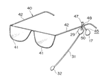
図3は眼鏡取付け型マイクロホン付きスピーカ装置45を、それが取付けられる眼鏡40と共に示す斜視図である。なお、図3以降の各図において、超指向性スピーカ17、骨伝導型スピーカ29、塑性変形管31、及びマイクロホン32は、耳掛け型マイクロホン付きスピーカ装置10(図1及び図2)の各部品と同一の構造であるので、耳掛け型マイクロホン付きスピーカ装置10のそれらと同一の符号を付している。 眼鏡取付け型マイクロホン付きスピーカ装置45は、片耳用として、超指向性スピーカ17を1個しか装備していないが、超指向性スピーカ17を左右1個ずつ装備するようにしてもよい。その場合、超指向性スピーカ17は左右計2個であっても、骨伝導型スピーカ29及びマイクロホン32は通常は1個のみである。眼鏡取付け型マイクロホン付きスピーカ装置45は、眼鏡40に適宜、取り外し自在に取付けられ、眼鏡40を介してユーザの顔に着脱自在にセットされる。眼鏡40は、左右の側方フレーム部分42と、左右の側方フレーム部分42の外側の端から後方へ延びる左右の側方フレーム部分42とを有している。眼鏡取付け型マイクロホン付きスピーカ装置45は装着部47を有し、フック48は、側方フレーム部分42の後端部にその上側から分離自在に掛けられるフック48を外側の面に備えている。側方フレーム部分42へのフック48の引っ掛け位置は側方フレーム部分42の延び方向へ任意となっている。塑性変形アーム50は、装着部47から斜め下方へ突出し、超指向性スピーカ17が、塑性変形アーム50の下端部に固定されている。ユーザは、塑性変形アーム50を適宜、塑性変形させて、超指向性スピーカ17の向き、外耳道18までの超指向性スピーカ17の距離、並びに超指向性スピーカ17の上下方向、左右方向、及び前後方向の位置を調整する。装着部47の下端部は上端部に対してユーザの顔面の方へ曲がっており、ユーザが眼鏡40を顔に掛けたときには、骨伝導型スピーカ29は、ユーザの側部顔面14に所定の押圧力で押圧される。塑性変形管31は、骨伝導型スピーカ29から延び出して、下端部にマイクロホン32を取付けられており、塑性変形によりマイクロホン32の位置を調整できるようになっている。
【0030】
図4はヘルメット型マイクロホン付きスピーカ装置55の外観図である。このヘルメット型マイクロホン付きスピーカ装置55は、自動二輪車のライダー用のものであるが、工場や土木、建築現場用のヘルメットにも同一の構造を採用可能である。 ヘルメット型マイクロホン付きスピーカ装置55は、片耳用として、超指向性スピーカ17を1個しか装備していないが、超指向性スピーカ17を左右1個ずつ装備するようにしてもよい。その場合、超指向性スピーカ17は左右計2個であっても、骨伝導型スピーカ29及びマイクロホン32は通常は1個のみである。圧縮コイルばね58は、ヘルメット56の内面の頂部に上端を固定され、下端部の方へ垂下している。骨伝導型スピーカ29は圧縮コイルばね58の下端に固定され、ユーザの頭部へのヘルメット56の装着時では、バンド(図示せず)を顎下で結ぶことにより、ヘルメット56は頭部に押し付けられ、圧縮コイルばね58は、圧縮されて、骨伝導型スピーカ29を所定の付勢力で頭部に押圧する。ステー60は、ヘルメット56の左側の下端部に上端部を固定され、所定長さだけ下方へ突出し、下端部には超指向性スピーカ17を取付けられている。超指向性スピーカ17は、ステー60の塑性変形により、向き、及び外耳道18までの距離を調整される。塑性変形管31は、上端部を超指向性スピーカ17に固定され、超指向性スピーカ17から下方へ延び出して、下端部にマイクロホン32を取付けられている。
【0031】
図5は帽子型マイクロホン付きスピーカ装置66の外観図である。 帽子型マイクロホン付きスピーカ装置66は、片耳用として、超指向性スピーカ17を1個しか装備していないが、超指向性スピーカ17を左右1個ずつ装備するようにしてもよい。その場合、超指向性スピーカ17は左右計2個であっても、骨伝導型スピーカ29及びマイクロホン32は通常は1個のみである。帽子67は、布地から製作され、前方へ張出す張出し部分と、頭に被さる被覆部分とから成る周知の構造となっている。 骨伝導型スピーカ29は、帽子67の被覆部分の周縁部内周側、例えば左側の内面部位に固定され、ユーザが帽子67を被ると、ユーザの頭部に所定力で押圧されるようになっている。ステー60は、この例では、帽子67の被覆部分において骨伝導型スピーカ29と同じ側に存在し、上端部を帽子67の被覆部分の下端部に固定され、帽子67から所定長さ、垂下している。超指向性スピーカ17は、ステー60の下端部に取付けられ、ステー60の塑性変形により、スピーカ面24の上下左右前後方向位置、スピーカ音の向き、及びスピーカ音から外耳道18間での距離を調整自在になっている。所定長さの塑性変形管31は、上端部において超指向性スピーカ17に結合し、下端部においてマイクロホン32を取付けられている。
【0032】
図6はカチュウシャ型マイクロホン付きスピーカ装置71の斜視図である。 カチュウシャ型マイクロホン付きスピーカ装置71は、片耳用として、超指向性スピーカ17を1個しか装備していないが、超指向性スピーカ17を左右1個ずつ装備するようにしてもよい。その場合、超指向性スピーカ17は左右計2個であっても、骨伝導型スピーカ29及びマイクロホン32は通常は1個のみである。カチュウシャ72は、拡開に対する復元力としての弾性力をもつ。骨伝導型スピーカ29は、カチュウシャ72の内面側の所定部位に固定され、ユーザの頭へのカチュウシャ72の装着時では、カチュウシャ72の弾性力によりユーザの頭部に押圧されて、頭部の所定の骨へ低音を伝動するようになっている。ステー60は、カチュウシャ72の左端部へ一端部を結合され、斜め下方の前方へ突出している。超指向性スピーカ17は、ステー60の他端部に取付けられ、ステー60の塑性変形により、スピーカ面24の上下左右方向位置、スピーカ音の向き、及びスピーカ音から外耳道18間での距離を調整自在になっている。所定長さの塑性変形管31は、上端部において超指向性スピーカ17に結合し、下端部においてマイクロホン32を取付けられている。
【図面の簡単な説明】
【図1】耳掛け型マイクロホン付きスピーカ装置をそのセット状態で示した図である。
【図2】前後方向へ外耳道の位置での耳の垂直断面と共に耳掛け型マイクロホン付きスピーカ装置を後方から示す図である。
【図3】眼鏡取付け型マイクロホン付きスピーカ装置を、それが取付けられる眼鏡と共に示す斜視図である。
【図4】ヘルメット型マイクロホン付きスピーカ装置の外観図である。
【図5】帽子型マイクロホン付きスピーカ装置の外観図である。
【図6】カチュウシャ型マイクロホン付きスピーカ装置の斜視図である。
【符号の説明】
10 耳掛け型マイクロホン付きスピーカ装置(身体セット型スピーカ装置)
11 耳掛け部(装着部材)
13 起立部(スピーカ保持部材)
17 超指向性スピーカ(指向性スピーカ)
26 外部開放空間(外部開放空間)
29 骨伝導型スピーカ
32 マイクロホン
40 眼鏡(装着部材)
45 眼鏡取付け型マイクロホン付きスピーカ装置(身体セット型スピーカ装置)
47 装着部(装着部材)
50 塑性変形アーム(スピーカ保持部材)
55 ヘルメット型マイクロホン付きスピーカ装置(身体セット型スピーカ装置)
56 ヘルメット(装着部材)
60 ステー(スピーカ保持部材)
66 帽子型マイクロホン付きスピーカ装置(身体セット型スピーカ装置)
67 帽子(外部開放空間)
71 カチュウシャ型マイクロホン付きスピーカ装置(身体セット型スピーカ装置)
72 カチュウシャ(装着部材)[0001]
BACKGROUND OF THE INVENTION
The present invention relates to a body-set type speaker device that outputs, for example, a reproduction sound of an audio device, a sound of a communication device, and the like, and more particularly, to a body-set type speaker device that can hear a speaker sound while securing the hearing of an external sound. Is.
[0002]
[Prior art]
As a device for listening to sound from an audio device, a personal computer, a communication device, etc., there are an earphone and a headphone. Moreover, people who put a small radio with a built-in speaker in a chest pocket such as a shirt and listen to the sound of a radio broadcast from the built-in speaker in the breast pocket are sometimes seen.
[0003]
[Problems to be solved by the invention]
In the earphone or the headphone, the ear is blocked with respect to the outside world, so that the user cannot hear the outside world sound but only the speaker sound. When listening to sound from a speaker placed around the ear, such as a breast pocket, listening to the external sound is ensured, but the speaker sound is scattered around and disturbs others.
[0004]
In the earphone disclosed in JP-A-8-33079, an elastic pad cover is placed on a miniature speaker, and the pad cover serves as a spacer by inserting the pad cover into the ear hole, so that the speaker surface has a predetermined distance from the ear hole. Is supposed to be held away. However, in this earphone, the space between the speaker surface and the ear hole is closed to the outside by the pad cover, and the outside sound is suppressed from reaching the ear hole.
[0005]
In addition, earphones may be worn only on one ear and another ear may be opened to hear external sounds, but listening to speaker sound and external sound separately from both ears may cause discomfort to the user. It is easy to cause fatigue on the auditory nerve. In addition, in order to listen to the speaker sound in stereo, earphones must be attached to both ears, and in that case, it is impossible to hear external sounds in combination with stereo sound with conventional earphones and headphones. It is.
[0006]
An object of the present invention is to provide a body-set type speaker device that allows a user to hear both external sound and speaker sound, and prevents leakage of speaker sound to the external environment.
[0007]
[Means for Solving the Problems]
The body-set type speaker device of the first invention has the following.
A mounting member that is detachably mounted on the user's body. When the speaker surface is directed toward the user's ear hole, the sound energy radiated from the speaker surface toward the ear hole corresponds to the total radiated sound energy from the speaker surface. A directional speaker that is coupled to a directional speaker / mounting member having a directivity that is equal to or greater than a predetermined value and that forms an external open space between the ear and the directional speaker, the directional speaker is a predetermined distance from the user's ear, Speaker holding member for holding it apart [0008]
The body set type speaker device is typically a headset type, but the “body set” of the “body set type” includes a set on other body parts such as a head, a face, a shoulder, a trunk, and an arm. Do not exclude. A directional speaker with a higher directivity can prevent leakage of the speaker sound to the outside world that causes noise even if it is placed away from the user's ear. If the directional speaker is as close as possible to the ear while ensuring the formation of an external open space, leakage of the speaker sound to the outside can be prevented in spite of some low directional performance. The ear hole is, for example, an opening of the ear canal to the outside world.
[0009]
Speaker sounds include CD, MD, DVD, and other optical disks and playback sounds that are recorded on IC memory by players, broadcast sounds output from radio and television broadcast tuners, and PCs. Sound, voice of the other party during a call via a mobile phone or a communication device, and the like are included. Users include personal computer operators and support center responders who respond to inquiries about goods and services over the phone. A body-set type speaker device typically inputs these sounds via wired or wireless, but is equipped with a small tuner, a telephone, and a communication device, and outputs these sounds from a directional speaker. In the case where it is designed to do so, it is possible to omit the radio and cable for receiving signals from the outside.
[0010]
Since the external open space is formed between the ear and the directional speaker, the ear is not blocked from the outside world, the external sound reaches the ear through the external open space, and the user You can hear both sounds. Further, the directional speaker has a standard for directivity (= the sound energy radiated from the speaker surface toward the ear hole when the speaker surface is directed toward the user's ear hole is predetermined with respect to the total radiated sound energy from the speaker surface. (A directivity that is greater than or equal to the value) is employed, and thereby leakage of speaker sound to the outside can be effectively prevented. In addition, since the user is guaranteed to listen to external sounds, this body-set type speaker device is set on the body only when listening to music, telephone calls, etc. While maintaining the state, the speaker sound from the body-set type speaker device can be heard when necessary.
[0011]
According to the body-set type speaker device of the second invention, in the first body-set type speaker device, the speaker holding member holds the directional speaker so that the distance from the directional speaker to the user's ear hole is adjustable. Yes.
[0012]
Since the distance from the directional speaker to the user's ear hole is adjustable, the body-set type speaker device can be used in conformity with the user's body shape. Further, by changing the distance from the directional speaker to the user's ear hole, the volume ratio between the external sound heard by the user and the speaker sound can be adjusted. Note that the volume setting means for adjusting the volume of the speaker sound is equipped in the body-set type speaker device, and the user can adjust the volume ratio between the speaker sound and the external sound appropriately by operating the volume adjustment means. it can.
[0013]
According to the body-set type speaker device of the third invention, in the body-set type speaker device of the first or second invention, the speaker holding member holds the directional speaker so that the direction of the directional speaker can be adjusted. Yes.
[0014]
By making the direction of the directional speaker adjustable, the body-set type speaker device can be used in conformity with the body shape of the user. Also, by changing the direction of the directional speaker, the volume ratio between the external sound heard by the user and the speaker sound can be adjusted as appropriate.
[0015]
According to the body-set type speaker device of the fourth invention, in any of the body-set type speaker devices of the first to third inventions, the sound signal that generates the sound output from the directional speaker is received wirelessly. It has become.
[0016]
According to the body-set type speaker device of the fifth invention, in any of the body-set type speaker devices of the first to third inventions, the sound signal that generates the sound output from the directional speaker is received by wire. It has become.
[0017]
A body-set type speaker device according to a sixth aspect of the present invention is the body-set type speaker device according to any one of the first to fifth aspects of the invention, equipped with a bone-conduction speaker that comes into contact with the user's body. The sound of the frequency below the value is transmitted to the user by bone conduction.
[0018]
“Sound having a frequency equal to or lower than a predetermined value” means a low tone, and the predetermined value is, for example, 250 Hz or less, preferably 150 Hz or less. The low sound has a short reach compared to the high sound, and it is difficult for the user to hear when the distance from the directional speaker to the user's ear hole is slightly away. In this body set type speaker device, since the low sound is transmitted to the user by the bone conduction type speaker, the user can surely hear the low sound.
[0019]
The body-set type speaker device according to a seventh aspect of the invention is the body-set type speaker device according to the sixth aspect, further comprising urging means for generating a urging force that presses the bone-conduction type speaker against the user's body.
[0020]
The urging means may be composed of a compression coil spring that is separate from the speaker holding member, or the speaker holding member is manufactured from a member having a predetermined spring force such as a leaf spring, and the speaker holding member is attached. Sometimes it also serves as a force.
[0021]
The body-set type speaker device according to an eighth aspect of the present invention is equipped with a microphone in any one of the body-set type speaker devices according to the first to eighth aspects.
[0022]
When the body-set type speaker device is also used for communication, recording of a user's voice, etc., it is beneficial that the body-set type speaker device is equipped with a microphone.
[0023]
According to the body-set type speaker device of the 90th invention, in any one of the body-set type speaker devices of the 1st to 8th inventions, one directional speaker is provided for each of the left and right ears of the user. Either two are equipped, or only one for the left and right ears.
[0024]
DETAILED DESCRIPTION OF THE INVENTION
Embodiments of the present invention will be described below with reference to the drawings.
FIG. 1 is a diagram showing the
[0025]
The
[0026]
The bone
[0027]
The
[0028]
Sounds other than low sounds, for example, sounds having a frequency higher than 150 Hz, are radiated from the
[0029]
FIG. 3 is a perspective view showing the
[0030]
FIG. 4 is an external view of the
[0031]
FIG. 5 is an external view of the
[0032]
FIG. 6 is a perspective view of the
[Brief description of the drawings]
FIG. 1 is a diagram showing a speaker device with an ear-mounted microphone in a set state.
FIG. 2 is a view showing a speaker device with an ear hook type microphone from the rear side along with a vertical section of an ear at a position of the ear canal in the front-rear direction.
FIG. 3 is a perspective view showing a speaker device with a spectacle-mounted microphone together with spectacles to which it is attached.
FIG. 4 is an external view of a speaker device with a helmet-type microphone.
FIG. 5 is an external view of a speaker device with a hat-type microphone.
FIG. 6 is a perspective view of a speaker device with a headband type microphone.
[Explanation of symbols]
10 Speaker device with ear hook type microphone (body set type speaker device)
11 Ear hook (mounting member)
13 Standing part (speaker holding member)
17 Super-directional speaker (directional speaker)
26 External open space (external open space)
29 Bone-
45 Speaker device with spectacle-mounted microphone (body-set type speaker device)
47 Mounting part (Mounting member)
50 Plastic deformation arm (speaker holding member)
55 Speaker device with helmet type microphone (body set type speaker device)
56 Helmet (Mounting member)
60 stay (speaker holding member)
66 Speaker device with hat type microphone (body set type speaker device)
67 Hat (Externally open space)
71 Speaker device with headband type microphone (body set type speaker device)
72 Headband (Mounting member)
Claims (9)
スピーカ面をユーザの耳穴の方へ向けたとき耳穴の方へスピーカ面から放射される音エネルギーがスピーカ面からの全放射音エネルギーに対して所定値以上になるような指向性を備える指向性スピーカ、及び
前記装着部材に結合されており耳と前記指向性スピーカとの間に外界音を耳に到達させる外部開放空間を形成するように前記指向性スピーカをユーザの耳穴から所定距離だけ離し、耳穴と対向させて保持するスピーカ保持部材、を有していることを特徴とする身体セット型スピーカ装置。A mounting member that is detachably mounted on the user's head;
A directional speaker having directivity such that when the speaker surface is directed toward the user's ear hole, the sound energy radiated from the speaker surface toward the ear hole is equal to or greater than a predetermined value with respect to the total radiated sound energy from the speaker surface. , and the separated by a predetermined distance the directional speaker so as to form an outer open space to reach the ears of the external sound from the ear hole of the user between the ears are coupled to the mounting member and the directional speaker, the ear canal A body-set type speaker device, comprising: a speaker holding member that is held opposite to the speaker.
Priority Applications (3)
| Application Number | Priority Date | Filing Date | Title |
|---|---|---|---|
| JP2000226413A JP3745602B2 (en) | 2000-07-27 | 2000-07-27 | Body set type speaker device |
| US09/916,027 US20020012441A1 (en) | 2000-07-27 | 2001-07-26 | Body set type speaker unit |
| US10/721,205 US20040105566A1 (en) | 2000-07-27 | 2003-11-25 | Body set type speaker unit |
Applications Claiming Priority (1)
| Application Number | Priority Date | Filing Date | Title |
|---|---|---|---|
| JP2000226413A JP3745602B2 (en) | 2000-07-27 | 2000-07-27 | Body set type speaker device |
Publications (2)
| Publication Number | Publication Date |
|---|---|
| JP2002058085A JP2002058085A (en) | 2002-02-22 |
| JP3745602B2 true JP3745602B2 (en) | 2006-02-15 |
Family
ID=18720036
Family Applications (1)
| Application Number | Title | Priority Date | Filing Date |
|---|---|---|---|
| JP2000226413A Expired - Fee Related JP3745602B2 (en) | 2000-07-27 | 2000-07-27 | Body set type speaker device |
Country Status (2)
| Country | Link |
|---|---|
| US (1) | US20020012441A1 (en) |
| JP (1) | JP3745602B2 (en) |
Families Citing this family (41)
| Publication number | Priority date | Publication date | Assignee | Title |
|---|---|---|---|---|
| JP3838072B2 (en) * | 2001-10-31 | 2006-10-25 | ソニー株式会社 | headphone |
| US20040226079A1 (en) * | 2002-08-09 | 2004-11-18 | Rainey Margaret A. | Helmet having audio features |
| US8849185B2 (en) | 2003-04-15 | 2014-09-30 | Ipventure, Inc. | Hybrid audio delivery system and method therefor |
| WO2004093488A2 (en) * | 2003-04-15 | 2004-10-28 | Ipventure, Inc. | Directional speakers |
| EP1732292A4 (en) * | 2004-03-31 | 2007-05-09 | Temco Japan | Talking device using bone conduction speaker |
| AT500786B1 (en) * | 2004-08-19 | 2011-08-15 | Anton Pfanner | HEARING PROTECTION AND / OR SPEAKER ELEMENT |
| US20080112581A1 (en) * | 2006-11-09 | 2008-05-15 | Stanley Kim | Vibrating earphone with enhanced base sound effect |
| US8526641B2 (en) * | 2008-03-31 | 2013-09-03 | Cochlear Limited | Customizable mass arrangements for bone conduction devices |
| US20090259090A1 (en) * | 2008-03-31 | 2009-10-15 | Cochlear Limited | Bone conduction hearing device having acoustic feedback reduction system |
| US9767817B2 (en) * | 2008-05-14 | 2017-09-19 | Sony Corporation | Adaptively filtering a microphone signal responsive to vibration sensed in a user's face while speaking |
| DE102009014327A1 (en) * | 2009-03-21 | 2010-09-23 | Bruckhoff Apparatebau Gmbh | Head set for use as hearing-aid glasses arrangement, head-band arrangement, frontlet system and ear-loops system for sound propagation by bone conduction, has mounting device for mounting on or in head of user |
| EP2144455B1 (en) * | 2008-07-07 | 2016-02-10 | Bruckhoff Apparatebau GmbH | Head set for bone conduction of the sound |
| JP4880059B1 (en) * | 2010-09-24 | 2012-02-22 | 西日本高速道路メンテナンス関西株式会社 | Headphone for helmet and helmet having the headphone |
| KR101600070B1 (en) * | 2010-12-27 | 2016-03-08 | 로무 가부시키가이샤 | Transmitter/receiver unit and receiver unit |
| US9313306B2 (en) | 2010-12-27 | 2016-04-12 | Rohm Co., Ltd. | Mobile telephone cartilage conduction unit for making contact with the ear cartilage |
| JP5783352B2 (en) | 2011-02-25 | 2015-09-24 | 株式会社ファインウェル | Conversation system, conversation system ring, mobile phone ring, ring-type mobile phone, and voice listening method |
| US9020168B2 (en) * | 2011-08-30 | 2015-04-28 | Nokia Corporation | Apparatus and method for audio delivery with different sound conduction transducers |
| KR101759047B1 (en) | 2012-01-20 | 2017-07-17 | 로무 가부시키가이샤 | Portable telephone having cartilage conduction section |
| KR20180061399A (en) | 2012-06-29 | 2018-06-07 | 로무 가부시키가이샤 | Stereo earphone |
| CN108551507A (en) | 2013-08-23 | 2018-09-18 | 罗姆股份有限公司 | Exhalation/incoming call communication, receiver, earphone, business card, non-contact IC card, mobile phone and its application method |
| US11412334B2 (en) * | 2013-10-23 | 2022-08-09 | Cochlear Limited | Contralateral sound capture with respect to stimulation energy source |
| KR102079893B1 (en) | 2013-10-24 | 2020-02-20 | 파인웰 씨오., 엘티디 | Wristband-type handset and wristband-type alerting device |
| JP6551919B2 (en) | 2014-08-20 | 2019-07-31 | 株式会社ファインウェル | Watch system, watch detection device and watch notification device |
| CN107113481B (en) | 2014-12-18 | 2019-06-28 | 株式会社精好 | Cartilage conduction hearing device using electromagnetic vibration unit and electromagnetic vibration unit |
| KR102056550B1 (en) | 2015-07-15 | 2019-12-16 | 파인웰 씨오., 엘티디 | Robots and Robotic Systems |
| JP6551929B2 (en) | 2015-09-16 | 2019-07-31 | 株式会社ファインウェル | Watch with earpiece function |
| EP3393109B1 (en) | 2016-01-19 | 2020-08-05 | FINEWELL Co., Ltd. | Pen-type transceiver device |
| EP3439316A4 (en) * | 2016-03-29 | 2019-03-27 | Sony Corporation | SOUND REPRODUCTION DEVICE |
| US10277971B2 (en) * | 2016-04-28 | 2019-04-30 | Roxilla Llc | Malleable earpiece for electronic devices |
| US9881600B1 (en) * | 2016-07-29 | 2018-01-30 | Bose Corporation | Acoustically open headphone with active noise reduction |
| US10542351B2 (en) * | 2016-09-22 | 2020-01-21 | Cochlear Limited | Coupling apparatuses for transcutaneous bone conduction devices |
| USD841619S1 (en) * | 2017-03-24 | 2019-02-26 | Klein Electronics, Inc. | Two-way radio headset with boom microphone |
| USD842839S1 (en) * | 2017-03-24 | 2019-03-12 | Klein Electronics, Inc. | Dual ear piece mobile phone headset with boom microphone |
| USD890099S1 (en) | 2018-05-16 | 2020-07-14 | Klein Electronics, Inc. | Ruggedized side connector for audio accessories |
| JP2020053948A (en) | 2018-09-28 | 2020-04-02 | 株式会社ファインウェル | Hearing device |
| US10631075B1 (en) * | 2018-11-12 | 2020-04-21 | Bose Corporation | Open ear audio device with bone conduction speaker |
| US10993016B2 (en) * | 2018-11-13 | 2021-04-27 | Timothy Val Kolton | Earphone with modular earfin and earhook fittings |
| USD975645S1 (en) | 2018-12-04 | 2023-01-17 | Klein Electronics, Inc. | Secure audio accessory connector |
| USD928740S1 (en) | 2019-08-30 | 2021-08-24 | Klein Electronics, Inc. | Touchscreen push-to-talk button |
| JP1707507S (en) * | 2021-09-21 | 2022-02-15 | headset | |
| USD1030702S1 (en) * | 2022-10-20 | 2024-06-11 | Freedman Electronics Pty Ltd | Headphone boom arm |
-
2000
- 2000-07-27 JP JP2000226413A patent/JP3745602B2/en not_active Expired - Fee Related
-
2001
- 2001-07-26 US US09/916,027 patent/US20020012441A1/en not_active Abandoned
Also Published As
| Publication number | Publication date |
|---|---|
| JP2002058085A (en) | 2002-02-22 |
| US20020012441A1 (en) | 2002-01-31 |
Similar Documents
| Publication | Publication Date | Title |
|---|---|---|
| JP3745602B2 (en) | Body set type speaker device | |
| US20040105566A1 (en) | Body set type speaker unit | |
| CN103081510B (en) | Ear-speaker | |
| CN1695401B (en) | Personal Wearable Communication and Speaker System | |
| US7580541B2 (en) | Personal audio-set with adjustable sliding ear clip mount | |
| JP4239404B2 (en) | Headphone device | |
| JP5473640B2 (en) | Speaker device | |
| CN100512335C (en) | Audio earphone | |
| US8213632B2 (en) | Electroacoustic transducer and ear speaker device | |
| US20020039427A1 (en) | Audio apparatus | |
| CN110089129A (en) | On head using the personal voice equipment of earpiece microphone/head detection outside | |
| US20070165899A1 (en) | Audio headphone | |
| JPWO2009116272A1 (en) | Bone conduction speaker and listening device using the same | |
| WO2019146138A1 (en) | Hearing device | |
| EP1843627B1 (en) | A personal voice-transmitted device | |
| KR100905252B1 (en) | Receiving device with opening structure | |
| CN112423182B (en) | Improved bone conduction earphone | |
| CN214799830U (en) | Ear-hanging type bone conduction earphone | |
| CN108243364A (en) | New bone conduction wearing earplugs | |
| CN220606042U (en) | Open wireless earphone | |
| WO2002030151A2 (en) | Audio apparatus | |
| JPH11229226A (en) | Helmet with speaker | |
| JP2003047083A (en) | Head set with built-in battery | |
| CN219287696U (en) | Headset earphone | |
| KR102664819B1 (en) | Bone Conduction Headset |
Legal Events
| Date | Code | Title | Description |
|---|---|---|---|
| A977 | Report on retrieval |
Free format text: JAPANESE INTERMEDIATE CODE: A971007 Effective date: 20040817 |
|
| A131 | Notification of reasons for refusal |
Free format text: JAPANESE INTERMEDIATE CODE: A131 Effective date: 20040831 |
|
| A521 | Written amendment |
Free format text: JAPANESE INTERMEDIATE CODE: A523 Effective date: 20041013 |
|
| A131 | Notification of reasons for refusal |
Free format text: JAPANESE INTERMEDIATE CODE: A131 Effective date: 20050105 |
|
| A521 | Written amendment |
Free format text: JAPANESE INTERMEDIATE CODE: A523 Effective date: 20050329 |
|
| TRDD | Decision of grant or rejection written | ||
| A01 | Written decision to grant a patent or to grant a registration (utility model) |
Free format text: JAPANESE INTERMEDIATE CODE: A01 Effective date: 20051026 |
|
| RD14 | Notification of resignation of power of sub attorney |
Free format text: JAPANESE INTERMEDIATE CODE: A7434 Effective date: 20051026 |
|
| A61 | First payment of annual fees (during grant procedure) |
Free format text: JAPANESE INTERMEDIATE CODE: A61 Effective date: 20051117 |
|
| R150 | Certificate of patent or registration of utility model |
Free format text: JAPANESE INTERMEDIATE CODE: R150 |
|
| LAPS | Cancellation because of no payment of annual fees |