JP3741677B2 - Wall-mounted microwave oven - Google Patents
Wall-mounted microwave oven Download PDFInfo
- Publication number
- JP3741677B2 JP3741677B2 JP2002258152A JP2002258152A JP3741677B2 JP 3741677 B2 JP3741677 B2 JP 3741677B2 JP 2002258152 A JP2002258152 A JP 2002258152A JP 2002258152 A JP2002258152 A JP 2002258152A JP 3741677 B2 JP3741677 B2 JP 3741677B2
- Authority
- JP
- Japan
- Prior art keywords
- air
- wall
- discharge port
- main body
- gas
- Prior art date
- Legal status (The legal status is an assumption and is not a legal conclusion. Google has not performed a legal analysis and makes no representation as to the accuracy of the status listed.)
- Expired - Fee Related
Links
Images


Classifications
-
- F—MECHANICAL ENGINEERING; LIGHTING; HEATING; WEAPONS; BLASTING
- F24—HEATING; RANGES; VENTILATING
- F24C—DOMESTIC STOVES OR RANGES ; DETAILS OF DOMESTIC STOVES OR RANGES, OF GENERAL APPLICATION
- F24C15/00—Details
- F24C15/20—Removing cooking fumes
-
- H—ELECTRICITY
- H05—ELECTRIC TECHNIQUES NOT OTHERWISE PROVIDED FOR
- H05B—ELECTRIC HEATING; ELECTRIC LIGHT SOURCES NOT OTHERWISE PROVIDED FOR; CIRCUIT ARRANGEMENTS FOR ELECTRIC LIGHT SOURCES, IN GENERAL
- H05B6/00—Heating by electric, magnetic or electromagnetic fields
- H05B6/64—Heating using microwaves
- H05B6/6426—Aspects relating to the exterior of the microwave heating apparatus, e.g. metal casing, power cord
- H05B6/6429—Aspects relating to mounting assemblies of wall-mounted microwave ovens
-
- F—MECHANICAL ENGINEERING; LIGHTING; HEATING; WEAPONS; BLASTING
- F24—HEATING; RANGES; VENTILATING
- F24C—DOMESTIC STOVES OR RANGES ; DETAILS OF DOMESTIC STOVES OR RANGES, OF GENERAL APPLICATION
- F24C15/00—Details
- F24C15/20—Removing cooking fumes
- F24C15/2028—Removing cooking fumes using an air curtain
-
- H—ELECTRICITY
- H05—ELECTRIC TECHNIQUES NOT OTHERWISE PROVIDED FOR
- H05B—ELECTRIC HEATING; ELECTRIC LIGHT SOURCES NOT OTHERWISE PROVIDED FOR; CIRCUIT ARRANGEMENTS FOR ELECTRIC LIGHT SOURCES, IN GENERAL
- H05B6/00—Heating by electric, magnetic or electromagnetic fields
- H05B6/64—Heating using microwaves
- H05B6/6402—Aspects relating to the microwave cavity
- H05B6/6405—Self-cleaning cavity
Landscapes
- Engineering & Computer Science (AREA)
- Physics & Mathematics (AREA)
- Electromagnetism (AREA)
- Chemical & Material Sciences (AREA)
- Combustion & Propulsion (AREA)
- Mechanical Engineering (AREA)
- General Engineering & Computer Science (AREA)
- Electric Ovens (AREA)
- Combinations Of Kitchen Furniture (AREA)
- Control Of High-Frequency Heating Circuits (AREA)
- Constitution Of High-Frequency Heating (AREA)
- Ventilation (AREA)
Description
【0001】
【発明の属する技術分野】
本発明は壁掛け型電子レンジに関し、より詳しくは下部のガスオーブンから上昇するガス及び煙の排出を案内するためのエアカーテン機能を有する壁掛け型電子レンジに関するものである。
【0002】
【従来の技術】
一般に、壁掛け型電子レンジはガスオーブンの上部の壁面に設置されるもので、通常の電子レンジが有する調理機能を果たすとともに、その下部のガスオーブンから上昇するガス及び煙などを外部へ排気する機能を果たすようにしたものである。
【0003】
図1は従来の壁掛け型電子レンジを示すものである。電子レンジの本体内には、飲食物調理のための調理室と、各種電装部品が設けられる電装室とが相互区画されて設けられる。そして、調理室及び電装室の周囲には、本体1の下部のガスオーブン2から発生するガス及び煙を排気させるための排気流路3が設けられ、本体1の後方上部には、排気流路3を介して本体1の下部から吸入されたガス及び煙を外部へ排気させる排気ファン4が設けられる。
【0004】
このような電子レンジによる排気動作は、内装排気ファン4が動作するにつれて、ガスオーブン2から発生したガス及び煙が本体1の下部に設けられた排気流路3の吸入口3aを通じて吸入され、吸入された空気が排気流路3を通じて外部へ排出されることからなる。
【0005】
ところが、このような壁掛け型電子レンジは、通常、その前後方向の幅“W1”がガスオーブン2の前後方向の幅“W2”より小さいため、排気ファン4により厨房空間の排気を行っても、ガスオーブン2から上昇するガス及び煙を十分に排出することができないとの問題点があった。
【0006】
すなわち、排気流路3の吸入口3aがたいていガスオーブン2の前方加熱部2aより後方の上部に位置するため、ガスオーブン2の後方加熱部2bから発生するガス及び煙は排気流路3の吸入口3aに円滑に吸入できるが、ガスオーブン2の前方加熱部2aから発生するガス及び煙の一部は吸入口3aに吸入されなくてそのまま上昇して厨房を汚染するとの問題点があった。
【0007】
【発明が解決しようとする課題】
したがって、本発明はこのような問題点を解決するためになされたもので、その目的は、本体から噴出するエアカーテンにより、ガスオーブンから上昇するガス及び煙を本体の下部吸入口側に案内して、ガス及び煙の排出を円滑にした壁掛け型電子レンジを提供することである。
【0008】
【課題を解決するための手段】
このような目的を達成するため、本発明は、ガスオーブンの上部の壁に装着される壁掛け型電子レンジにおいて、区画板と、前記区画板により相互区画された調理室と電装室を有し、前記壁に装着される本体と、前記ガスオーブンから発生したガス及び煙を排気させるため、前記本体内に設けられる排気流路と、前記排気流路に流入された前記ガス及び煙を外部へ排気させる排気ファンと、前記ガスオーブンから発生したガス及び煙を前記排気流路側に案内するエアカーテンを形成するため、前記本体の前方下部に設けられた空気吐出口と、空気を前記空気吐出口側に送風するため、前記本体内に設けられる送風ファンとを含む壁掛け型電子レンジを提供する。
【0009】
前記電装室の内部を冷却させながら前記空気を前記空気吐出口側に案内するため、前記送風ファンは前記電装室内に設けることができる。
【0010】
前記空気吐出口は前記本体の前方下部で横方向に延長され、前記本体は前記電装室から案内された空気を前記空気吐出口側に案内するため、流路を形成する空気案内ダクトを有する底板をさらに含むことができる。
【0011】
前記本体は、前記本体の前面上部に設けられ、前記送風ファンの駆動により前記空気が前記電装室内に流入されるようにする吸入口をさらに含むことができる。
【0012】
前記電装室は、前記吸入口を通じて流入される空気を循環させ前記空気吐出口側に案内するため、前記吸入口に近い前記電装室の前方空間を上部空間と下部空間に区画する空気案内板を含み、前記送風ファンは前記空気案内板の上部空間内に設けることができる。
【0013】
前記調理室と前記電装室の境界をなす前記区画板は、前記電装室内で循環する空気の一部が前記調理室内に流入できるように少なくとも一つの通孔を含むことができる。
【0014】
前記空気吐出口は前記本体の前方下部で横方向に延長され、前記本体は、前記電装室から案内された空気を前記空気吐出口側に案内するため、流路を形成する空気案内ダクトを有する底板をさらに含むことができる。
【0015】
【発明の実施の形態】
以下、本発明による好ましい実施形態を添付図面に基づいて詳細に説明する。図2ないし図5は本発明による壁掛け型電子レンジを示す。図2に示すように、壁掛け型電子レンジの本体10はガスオーブン100の上部の厨房壁面に固定される。この本体10の内部には、図3及び図4に示すように、飲食物の調理のための調理室11と、各種電気部品が内装される電装室12とが相互区画されるように形成される。また、調理室11及び電装室12から区画される本体10の下部空間と両側方と上側方には、本体10の下部のガスオーブン100から発生するガス及び煙を排気させるための排気流路が設けられ、本体10の上側後方には、排気流路に沿って案内されるガス及び煙を外部へ排出させるための排気ファン13が設けられる。
【0016】
図3及び図4に示すように、調理室11の内部には、調理物が載置される回転可能なターンテーブル14が設けられ、調理室11の底部にはターンテーブル14を回転させる駆動手段として、通常のモータ15が設けられる。そして、調理室11の前面には、調理室11内に調理物が収納できるよう、開閉可能なドア16が取り付けられる。
【0017】
電装室12内には、調理室11の内部に高周波を供給するためのマグネトロン17と、マグネトロン17に高電圧を印加するための高圧トランス18及び高圧コンデンサー19とが内装される。また、電装室12の前面には電子レンジの各種機能を操作するための多数の操作ボタンが設けられた操作パネル20が設けられる。ここで、マグネトロン17は電装室12の上部に配設され、高圧トランス18は電装室12の底面に取り付けられ、高圧コンデンサー19は電装室12の後方に取り付けられる。また、マグネトロン17の位置に対応する電装室12の上部と調理室11の上部には、マグネトロン17から発生する高周波が調理室11の内部に案内されるように、通常の導波管21が設けられる。
【0018】
本体10の下部から生じるガス、煙などを排気させるための排気流路は、図3ないし図5に示すように、本体10の下部の底板22に形成された排気用吸入口22a、調理室11及び電装室12の下面と底板22の上面との離隔空間に設けられる下部流路23、調理室11の側方及び電装室12の後方に上下方向に設けられた二つの上昇流路24、25と、前記二つの上昇流路24、25に沿って案内されたガス及び煙を排気ファン13側に案内するように、本体10の上部に設けられた上部流路26とからなる。これは、排気ファン13が駆動するとき、底板22の吸入口22aを通じて吸入されたガス及び煙が下部流路23、上昇流路24、25、及び上部流路26を順次経て排出されるようにしたものである。
【0019】
また、本発明による電子レンジは、本体10の前方下部から吐き出される空気により形成されるエアカーテン“A”により、下部のガスオーブン100から上昇するガス及び煙が本体10の下部の排気用吸入口22a側に案内する機能を果たす。この機能のためのものとして、本体10の前方下部には、エアカーテン“A”を形成する空気の吐出のための空気吐出口30が形成され、電装室12の内部には、室内空気を吸入して空気吐出口30側に強制送風するための送風ファン31が設けられる。
【0020】
また、電装室12の前面上部(操作パネルの上部)には、電装室12の内部に設けられた送風ファン31が駆動するとき、室内の空気を電装室12の内部に吸入するための吸入口32が形成され、電装室12の底板33の前方には、電装室12の内部に流入された空気を本体10の下部の空気吐出口30側に吐き出すため、電装室12の内部と空気吐出口30が連通するようにする貫通孔34が形成されている。
【0021】
また、電装室12の内部には、吸入口32を通じて吸入された空気が電装室12の内部を循環しながら電装室12を冷却させた後、下部の貫通孔34を通じて空気吐出口30側に吐き出されるよう、電装室12の前方空間を上部と下部に区画して空気の流れを案内する空気案内板35が設けられる。そして、送風ファン31は空気案内板35の上部空間に設けられるが、吸入された空気を電装室12の内側に送風するため、送風方向が電装室12の内側後方に向かうように配設される。本実施形態において、電装室12の内部の送風ファン31は電装室12の内部の冷却機能と、エアカーテン“A”の形成のための空気の送風機能とを兼ねるようになっているが、電装室12の内部に、エアカーテン“A”の形成のための送風ファンと電装室の冷却だけのための送風ファンとを別に設けて別途の機能を果たすようにすることもできる。
【0022】
本体10の前方下部に設けられる空気吐出口30は、本体10の幅にほぼ対応する幅を有するように、本体10の底板22の前端に横方向に長く形成される。また、空気吐出口30には、吐き出される空気を本体10の前方下部の方向に案内するため、空気吐出口30から空気の吐出方向に(底板の外側方向に)所定長さだけ延長された吐出案内部37が設けられる。
【0023】
また、空気吐出口30が形成された側の本体10の底板22には、電装室12の下部の貫通孔34を通じて吐き出される空気を調理室11の下部に位置する空気吐出口30側に案内する流路を形成する空気案内ダクト38が設けられる。空気案内ダクト38は調理室12の下部に位置する空気吐出口30の上部を覆う長さを有し、電装室12の下部の貫通孔34に近い端部に開放部38aを有する。また、電装室12の下部側に位置する底板22の上面には、電装室12から吐出口30側に吐き出される空気を、本体10の下部の吸入口22aを通じて排気流路23に流れるガスから隔離するための分離板39が設けられる(図5参照)。図6に示すように、底板22には二つの吸入口22aが提供できる。
【0024】
図3及び図4に示すように、本発明による壁掛け型電子レンジの電装室11と調理室12とを区画する区画板40には、送風ファン31の駆動により、電装室12の内部の循環する空気の一部が調理室11の内部に流入して調理室11を換気させるため、複数の通孔41が形成され、区画板40の対向側に位置する調理室11の上部には、調理室11の内部空気の排出のための通孔42と前面排出口43が設けられる。ここで、送風ファン31の駆動により電装室12を循環する空気は、調理室11の換気のための一部空気を除いた残りの空気が電装室12を経て空気吐出口30側に吐き出されるようにすることが好ましい。
【0025】
つぎに、このように構成された本発明による壁掛け型電子レンジの動作を図2ない図5に基づいて説明する。
【0026】
調理を行うに際して、図4に示すように、電装室12内に設けられたマグネトロン17から発生される高周波が導波管21を通じて調理室11の内部に発生されることにより、調理室11に収納された調理物の調理がなされる。図4に示すように、調理室11の換気動作は、電装室12内に設けられた送風ファン31の駆動により、電装室12の内部に流入された空気の一部が区画板40の通孔41を通じて調理室11に流入することからなる。すなわち、電装室12を循環する空気の一部は区画板40の通孔41を通じて調理室11の内部に流入され、水蒸気を含む調理室11の内部空気は調理室11の上部の通孔42と前面排気口43を通じて排出されることにより、調理室11の換気が成される。この際、電装室12の内部に流入される空気により電装室12に内装された電気部品が冷却される。
【0027】
このような調理動作と同時に、本体10の下部のガスオーブン100から発生したガス及び煙の排気動作を行うに際して、使用者が操作パネル20に設けられた排気機能ボタン(図示せず)を操作すると、本体10の後方上部に設けられた排気ファン13が動作し、排気ファン13の動作により、本体10の下部のガス及び煙が排気流路を通じて外部へ排出される。すなわち、排気ファン13が動作すると、ガスオーブン100から発生するガス及び煙は本体10の下部の排気用吸入口22aを通じて下部流路23に流入され、下部流路23に流入された空気は調理室11の側方と電装室12の後方にそれぞれ設けられた二つの上昇流路24、25に沿って上昇し、続いて本体10の上部に設けられた上部流路26に沿って排気ファン13側に流れ外部へ排出される。
【0028】
また、図2及び図5に示すように、このような排気動作が行われる間、電装室12の内部の送風ファン31を同時に駆動することにより、本体10の前方下部にエアカーテン“A”が形成される。すなわち、送風ファン31を駆動すると、電装室12の上部の吸入口32を通じて吸入された空気が電装室12の内部に流入して電装室12を冷却させた後、本体10の前方下部に設けられた空気吐出口30側に吐き出されることにより、エアカーテン“A”を形成する。この際、電装室12の内部の空気案内板35は、吸入口32を通じて電装室12に流入された空気が電装室12を循環することで電装室12の冷却機能を果たし、本体の底板22の空気案内ダクト38は吐き出される空気が横方向に長く形成された空気吐出口30の全域にわたって均等に分散されて吐き出されるようにする機能を果たす。
【0029】
本体10の前方下部に吐き出されるエアカーテン“A”は、図2に示すように、所定の傾きで本体10の前方下部に噴出されて、空気の境界幕を形成する。そして、このようなエアカーテン“A”は、ガスオーブン100から上昇するガス及び煙の上昇を遮断するとともに、ガス及び煙を本体10の下部の吸入口22a側に誘導して外部へ排出することにより、ガス及び煙による室内空間の汚染を防止する機能を果たす。特に、エアカーテン“A”はガスオーブン100の前方加熱部110から生じるガス及び煙を本体10の下部の排気用吸入口22a側に誘導して外部へ排出する。
【0030】
【発明の効果】
以上説明したように、本発明による壁掛け型電子レンジは、本体の前方下部に噴出されるエアカーテンにより、ガスオーブンから上昇するガス及び煙を本体の下部の吸入口側に誘導して外部へ排出することができるので、ガス及び煙による室内空間の汚染を防止することができる効果がある。
【0031】
また、本発明は、電装室の内部に設けられる送風ファンをもって電装室の冷却機能とエアカーテン機能を同時に果たし得る構造であるので、製造費の面で有利な効果がある。
【0032】
以上本発明を壁掛け型電子レンジを参照して説明したが、本発明はほかの調理装置から発生するガス及び煙を排出させるのに適したほかの調理装置にも適用することができる。すなわち、本発明は、例えばほかの調理装置から発生するガス及び煙を排出する、トースター機、対流式オーブン、及び電子レンジ/対流式オーブンなどの複合調理装置にも適用することができる。
【0033】
また、本発明の空気吐出口は、操作パネルの制御選択により、少なくとも一つの直線形、アーチ形、半円形、及び円形の縁部形状を有するエアカーテンを噴出するように設計できる。そのうえ、本発明の空気吐出口は調理装置の特定燃焼部側にエアカーテンが噴出されるように設計することもできる。
【図面の簡単な説明】
【図1】 ガスオーブンの上方に装着された従来の壁掛け型電子レンジの使用状態を示す側断面図である。
【図2】 本発明の一実施形態による壁掛け型電子レンジの使用状態を示す側断面図である。
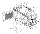
【図3】 図2に示す壁掛け型電子レンジの構造を示す斜視図である。
【図4】 図3に示す壁掛け型電子レンジの構造を示す正断面図である。
【図5】 図2ないし図4に示す壁掛け型電子レンジの電装室の構造を示す拡大断面図である。
【図6】 図2ないし図5に示す壁掛け型電子レンジの本体底板の構造を示す斜視図である。
【符号の説明】
10 本体
11 調理室
12 電装室
13 排気ファン
17 マグネトロン
18 高圧トランス
20 操作パネル
21 導波管
22 本体の底板
22a 排気用吸入口
23、24、25、26 排気流路
30 空気吐出口
31 送風ファン
34 貫通孔
35 空気案内板
37 吐出案内部
38 空気案内ダクト
39 分離板
41 通孔
A エアカーテン[0001]
BACKGROUND OF THE INVENTION
The present invention relates to a wall-mounted microwave oven, and more particularly to a wall-mounted microwave oven having an air curtain function for guiding discharge of gas and smoke rising from a lower gas oven.
[0002]
[Prior art]
In general, a wall-mounted microwave oven is installed on the upper wall of a gas oven, and performs the cooking function of an ordinary microwave oven, as well as the function of exhausting gas and smoke rising from the lower gas oven to the outside. It is intended to fulfill.
[0003]
FIG. 1 shows a conventional wall-mounted microwave oven. In the main body of the microwave oven, a cooking room for cooking food and an electrical room in which various electrical components are provided are provided in a mutually partitioned manner. An exhaust passage 3 for exhausting gas and smoke generated from the
[0004]
In such an exhaust operation by the microwave oven, as the internal exhaust fan 4 operates, the gas and smoke generated from the
[0005]
However, such a wall-mounted microwave oven usually has a width “W1” in the front-rear direction smaller than a width “W2” in the front-rear direction of the
[0006]
That is, since the
[0007]
[Problems to be solved by the invention]
Therefore, the present invention has been made to solve such problems, and its purpose is to guide the gas and smoke rising from the gas oven to the lower suction port side of the main body by the air curtain ejected from the main body. And providing a wall-mounted microwave oven that smoothly discharges gas and smoke.
[0008]
[Means for Solving the Problems]
In order to achieve such an object, the present invention, in a wall-mounted microwave oven mounted on the upper wall of a gas oven, has a partition plate, a cooking chamber and an electrical component chamber mutually partitioned by the partition plate, In order to exhaust the gas and smoke generated from the main body mounted on the wall and the gas oven, the exhaust passage provided in the main body, and the gas and smoke flowing into the exhaust passage are exhausted to the outside. An exhaust fan, an air curtain for guiding gas and smoke generated from the gas oven to the exhaust flow path side, and an air discharge port provided at a front lower portion of the main body, and air is supplied to the air discharge port side A wall-mounted microwave oven including a blower fan provided in the main body is provided.
[0009]
In order to guide the air to the air discharge port side while cooling the interior of the electrical component chamber, the blower fan can be provided in the electrical component chamber.
[0010]
The air discharge port is extended laterally at a lower front portion of the main body, and the main body has a bottom plate having an air guide duct that forms a flow path for guiding air guided from the electrical component chamber to the air discharge port side. Can further be included.
[0011]
The main body may further include a suction port provided at an upper portion of the front surface of the main body and configured to allow the air to flow into the electrical component chamber by driving the blower fan.
[0012]
The electrical compartment circulates air flowing in through the suction port and guides it toward the air discharge port. Therefore, an air guide plate that divides the front space of the electrical compartment near the suction port into an upper space and a lower space is provided. The blower fan may be provided in an upper space of the air guide plate.
[0013]
The partition plate that forms a boundary between the cooking chamber and the electrical component chamber may include at least one through hole so that a part of the air circulating in the electrical component chamber can flow into the cooking chamber.
[0014]
The air discharge port extends laterally at a lower front portion of the main body, and the main body has an air guide duct that forms a flow path for guiding the air guided from the electrical component chamber to the air discharge port side. A bottom plate can be further included.
[0015]
DETAILED DESCRIPTION OF THE INVENTION
Hereinafter, preferred embodiments of the present invention will be described in detail with reference to the accompanying drawings. 2 to 5 show a wall-mounted microwave oven according to the present invention. As shown in FIG. 2, the
[0016]
As shown in FIG. 3 and FIG. 4, a rotatable turntable 14 on which a food item is placed is provided inside the
[0017]
A
[0018]
As shown in FIGS. 3 to 5, the exhaust passage for exhausting gas, smoke, and the like generated from the lower portion of the
[0019]
In addition, the microwave oven according to the present invention is configured such that the gas and smoke rising from the
[0020]
Further, a suction port for sucking indoor air into the interior of the
[0021]
In the interior of the
[0022]
The
[0023]
Further, the air discharged from the
[0024]
As shown in FIG. 3 and FIG. 4, the
[0025]
Next, the operation of the wall-mounted microwave oven configured as described above according to the present invention will be described with reference to FIG.
[0026]
When cooking, as shown in FIG. 4, the high frequency generated from the
[0027]
When the user operates an exhaust function button (not shown) provided on the
[0028]
Further, as shown in FIGS. 2 and 5, while such an exhausting operation is performed, the air curtain “A” is formed in the lower front portion of the
[0029]
As shown in FIG. 2, the air curtain “A” discharged to the lower front part of the
[0030]
【The invention's effect】
As described above, the wall-mounted microwave oven according to the present invention guides the gas and smoke rising from the gas oven to the suction port side at the lower part of the main body and discharges it to the outside by the air curtain ejected to the lower front part of the main body. Therefore, it is possible to prevent the indoor space from being contaminated by gas and smoke.
[0031]
Moreover, since this invention is a structure which can perform the cooling function of an electrical equipment chamber and an air curtain function simultaneously with the ventilation fan provided in the inside of an electrical equipment chamber, there exists an advantageous effect in terms of manufacturing cost.
[0032]
Although the present invention has been described with reference to a wall-mounted microwave oven, the present invention can also be applied to other cooking apparatuses suitable for discharging gas and smoke generated from other cooking apparatuses. That is, the present invention can also be applied to combined cooking devices such as toaster machines, convection ovens, and microwave / convection ovens that discharge gas and smoke generated from other cooking devices, for example.
[0033]
In addition, the air discharge port of the present invention can be designed to eject an air curtain having at least one linear shape, arch shape, semicircular shape, and circular edge shape by control selection of the operation panel. Moreover, the air outlet of the present invention can be designed so that the air curtain is ejected to the specific combustion part side of the cooking apparatus.
[Brief description of the drawings]
FIG. 1 is a side sectional view showing a use state of a conventional wall-mounted microwave oven mounted above a gas oven.
FIG. 2 is a side cross-sectional view showing a usage state of a wall-mounted microwave oven according to an embodiment of the present invention.
3 is a perspective view showing the structure of the wall-mounted microwave oven shown in FIG. 2. FIG.
4 is a front sectional view showing the structure of the wall-mounted microwave oven shown in FIG. 3. FIG.
5 is an enlarged cross-sectional view showing the structure of the electrical compartment of the wall-mounted microwave oven shown in FIGS. 2 to 4. FIG.
6 is a perspective view showing a structure of a main body bottom plate of the wall-mounted microwave oven shown in FIGS. 2 to 5. FIG.
[Explanation of symbols]
DESCRIPTION OF
Claims (21)
区画板と、
前記区画板により相互区画された調理室と電装室を有し、前記壁に装着される本体と、
前記ガスオーブンから発生したガス及び煙を排気させるため、前記本体内に設けられる排気流路と、
前記排気流路に流入された前記ガス及び煙を外部へ排気させる排気ファンと、
前記ガスオーブンから発生したガス及び煙を前記排気流路側に案内するエアカーテンを形成するため、前記本体の前方下部に設けられた空気吐出口と、
空気を前記空気吐出口側に送風するため、前記本体内に設けられる送風ファンとを含み、
前記電装室の内部を冷却させながら前記空気を前記空気吐出口側に案内するため、前記送風ファンは前記電装室内に設けられることを特徴とする壁掛け型電子レンジ。In a wall-mounted microwave oven mounted on the upper wall of the gas oven,
A partition plate;
A cooking chamber and an electrical component room that are mutually partitioned by the partition plate, and a main body mounted on the wall;
In order to exhaust the gas and smoke generated from the gas oven, an exhaust passage provided in the main body,
An exhaust fan for exhausting the gas and smoke flowing into the exhaust passage to the outside;
In order to form an air curtain that guides gas and smoke generated from the gas oven to the exhaust flow path side, an air discharge port provided at the front lower part of the main body,
In order to blow air to the air outlet side, including a blower fan provided in the main body ,
For guiding the air while cooling the interior of the electric element chamber to the air discharge port side, the blower fan is wall-mounted microwave oven characterized that you provided in the electrical chamber.
前記本体は前記電装室から案内された空気を前記空気吐出口側に案内するため、流路を形成する空気案内ダクトを有する底板をさらに含むことを特徴とする請求項1記載の壁掛け型電子レンジ。The air discharge port is extended laterally at the front lower part of the main body,
It said body for guiding the air guided from the electric element chamber to the air discharge port side, wall-mounted microwave according to claim 1 Symbol placement, further comprising a bottom plate having an air guide duct to form a flow path range.
前記送風ファンの駆動により前記空気が前記電装室内に流入されるようにする吸入口をさらに含むことを特徴とする請求項1記載の壁掛け型電子レンジ。The main body is provided on an upper front portion of the main body,
Claim 1 Symbol mounting wall-mounted microwave oven, wherein the air by driving the blower fan further comprises an inlet to be introduced into the electrical chamber.
前記送風ファンは前記空気案内板の上部空間内に設けられることを特徴とする請求項3記載の壁掛け型電子レンジ。The electrical compartment circulates air flowing in through the suction port and guides it toward the air discharge port. Therefore, an air guide plate that divides the front space of the electrical compartment near the suction port into an upper space and a lower space is provided. Including
The blowing fan is wall-mounted microwave oven according to claim 3 Symbol mounting, characterized in that provided in the upper space of the air guide plate.
前記本体は、前記電装室から案内された空気を前記空気吐出口側に案内するため、流路を形成する空気案内ダクトを有する底板をさらに含むことを特徴とする請求項1記載の壁掛け型電子レンジ。The air discharge port is extended laterally at the front lower part of the main body,
The wall-mounted electron according to claim 1, wherein the main body further includes a bottom plate having an air guide duct that forms a flow path for guiding the air guided from the electrical component room to the air discharge port side. range.
下部に存在するガス及び煙を排気させるため、排気流路を有する本体と、
前記ガス及び煙を前記排気流路側に案内するためのエアカーテンを形成するため、前記本体の前方下部に設けられる空気吐出口と、
空気を吸入して前記空気吐出口側に送風する送風ファンとを含み、
前記本体は、前記空気吐出口に連通する通孔を有する調理室と電装室をさらに含み、
前記送風ファンは前記電装室内に配設され、前記空気を前記通孔を通じて空気吐出口側に送風しながら前記電装室を同時に冷却することを特徴とする壁掛け型電子レンジ。In a wall-mounted microwave oven,
A main body having an exhaust passage for exhausting the gas and smoke present in the lower part;
In order to form an air curtain for guiding the gas and smoke to the exhaust flow path side, an air discharge port provided at a lower front portion of the main body,
A blower fan that sucks air and blows air to the air discharge port side ;
The main body further includes a cooking chamber having a through hole communicating with the air outlet and an electrical component chamber,
The blowing fan is disposed in the electrical compartment, wall-mounted microwave oven, wherein the simultaneous cooling child the machine room while blowing the air to the air discharge port side through the through hole.
飲食物に高周波を発生させるマグネトロンと、
前記マグネトロンに電圧を印加する高電圧トランスと、
飲食物が載置されるターンテーブルを有する調理室と、
前記ターンテーブルを回転させる駆動モータと、
前記マグネトロンから発生された高周波を前記調理室側に案内する導波管とを含むことを特徴とする請求項8記載の壁掛け型電子レンジ。The wall-mounted microwave oven is
Magnetron that generates high frequency in food and drink,
A high voltage transformer for applying a voltage to the magnetron;
A cooking chamber having a turntable on which food and drink are placed;
A drive motor for rotating the turntable;
Wall-mounted microwave oven according to claim 8 Symbol mounting, characterized in that it comprises a waveguide for guiding the microwaves generated from the magnetron to the cooking chamber side.
ガス及び煙が通過できるように、前記本体の底板に形成される吸入口と、
前記底板と前記吸入口の上部空間を形成する下部流路と、
前記本体の対応側に設けられ、前記下部流路に連通する上昇流路と、
前記上昇流路に連通し、前記ガス及び煙を排気させるため、外部に連通する上部流路とを含むことを特徴とする請求項8記載の壁掛け型電子レンジ。The exhaust passage is
A suction port formed in the bottom plate of the body so that gas and smoke can pass through;
A lower flow path forming an upper space of the bottom plate and the suction port;
An ascending flow path provided on a corresponding side of the main body and communicating with the lower flow path;
Said communicating with the upward flow path, in order to exhaust the gas and smoke, wall-mounted microwave oven according to claim 8 Symbol mounting, characterized in that it comprises an upper passage communicating with the outside.
空気を噴出して前記エアカーテンを形成する吐出案内部と、
前記通孔を通じて流入された空気を前記吐出案内部側に案内する空気案内ダクトと、
前記電装室から流入された空気を、前記排気流路側に流れるガス及び煙から分離するため、前記通孔に対応して配設される分離板とを含むことを特徴とする請求項8記載の壁掛け型電子レンジ。The air outlet is
A discharge guide part for ejecting air to form the air curtain;
An air guide duct for guiding the air introduced through the through hole to the discharge guide portion side;
The air discharged from the machine room, to separate from the gas and smoke flowing in the exhaust passage side, claim 8 Symbol mounting, characterized in that it comprises a separation plate which is disposed corresponding to the hole Wall-mounted microwave oven.
前記飲食物を調理する加熱部と、
前記本体の排気流路側にガス及び煙を案内するエアカーテンを形成する空気吐出口と、
前記空気吐出口側に空気を噴出する送風ファンとを含み、
前記調理装置は調理動作を制御する操作パネルを含むが、前記空気吐出口は前記操作パネルの制御信号に応じて選択的にエアカーテンを形成し、
前記空気吐出口は前記操作パネルの制御選択に応じて、少なくとも一つの直線形、アーチ形、半円形及び円形の少なくとも一つの縁部形状を有するエアカーテンを形成することを特徴とする調理装置。A cooking chamber for storing food and drink, and a main body having an exhaust passage for exhausting gas and smoke present in the lower part;
A heating unit for cooking the food and drink;
An air outlet that forms an air curtain for guiding gas and smoke on the exhaust flow path side of the main body;
A blower fan that blows out air to the air outlet side ,
The cooking device includes an operation panel for controlling a cooking operation, but the air discharge port selectively forms an air curtain according to a control signal of the operation panel,
It said air discharge port in response to control selection of the operation panel, at least one straight, arcuate, cooking apparatus characterized that you form an air curtain having a semi-circular and circular least one edge shape .
Applications Claiming Priority (2)
| Application Number | Priority Date | Filing Date | Title |
|---|---|---|---|
| KR10-2002-0028759A KR100419206B1 (en) | 2002-05-23 | 2002-05-23 | Wall mounting type microwave oven |
| KR2002-028759 | 2002-05-23 |
Publications (2)
| Publication Number | Publication Date |
|---|---|
| JP2003343855A JP2003343855A (en) | 2003-12-03 |
| JP3741677B2 true JP3741677B2 (en) | 2006-02-01 |
Family
ID=27800701
Family Applications (1)
| Application Number | Title | Priority Date | Filing Date |
|---|---|---|---|
| JP2002258152A Expired - Fee Related JP3741677B2 (en) | 2002-05-23 | 2002-09-03 | Wall-mounted microwave oven |
Country Status (5)
| Country | Link |
|---|---|
| US (1) | US6621058B1 (en) |
| EP (1) | EP1365630A3 (en) |
| JP (1) | JP3741677B2 (en) |
| KR (1) | KR100419206B1 (en) |
| CN (1) | CN100451453C (en) |
Families Citing this family (60)
| Publication number | Priority date | Publication date | Assignee | Title |
|---|---|---|---|---|
| US6894260B2 (en) * | 2001-12-04 | 2005-05-17 | Matsushita Electric Industrial Co., Ltd. | High frequency heating apparatus |
| KR100432229B1 (en) * | 2002-07-08 | 2004-05-20 | 삼성전자주식회사 | Wall mounting type microwave oven |
| KR20040043021A (en) * | 2002-11-15 | 2004-05-22 | 삼성전자주식회사 | Microwave oven having a toaster |
| KR20040096136A (en) * | 2003-05-07 | 2004-11-16 | 삼성전자주식회사 | Oven for baking bread |
| US7375310B2 (en) * | 2003-07-21 | 2008-05-20 | Lg Electronics, Inc. | Air flow system for circulating air in a microwave oven |
| US20070194015A1 (en) * | 2003-10-16 | 2007-08-23 | Kim Kyu Y | Microwave oven |
| KR100565222B1 (en) * | 2003-11-03 | 2006-03-30 | 엘지전자 주식회사 | Hood guide microwave exhaust guide |
| KR100609156B1 (en) * | 2004-02-26 | 2006-08-02 | 엘지전자 주식회사 | Hooded microwave oven |
| KR100705098B1 (en) | 2004-03-09 | 2007-04-06 | 엘지전자 주식회사 | Hooded microwave oven |
| KR100609910B1 (en) | 2004-08-04 | 2006-08-09 | 삼성전자주식회사 | microwave |
| KR100699257B1 (en) | 2004-08-09 | 2007-03-27 | 삼성전자주식회사 | microwave |
| CN100455895C (en) * | 2004-09-20 | 2009-01-28 | 乐金电子(天津)电器有限公司 | Upper pipeline for microwave oven |
| KR100739156B1 (en) * | 2005-02-05 | 2007-07-13 | 엘지전자 주식회사 | Hooded microwave oven |
| JP4603901B2 (en) * | 2005-02-15 | 2010-12-22 | シャープ株式会社 | Built-in kitchen equipment |
| ITPN20050012A1 (en) * | 2005-02-17 | 2006-08-18 | Electrolux Professional Spa | PERFECTED HOOD |
| US7699051B2 (en) * | 2005-06-08 | 2010-04-20 | Westen Industries, Inc. | Range hood |
| US8941041B2 (en) * | 2006-09-01 | 2015-01-27 | Lg Electronics Inc. | Cooking apparatus having a cooling system |
| KR100901890B1 (en) * | 2006-09-12 | 2009-06-10 | 엘지전자 주식회사 | Cooker |
| KR20080024025A (en) | 2006-09-12 | 2008-03-17 | 엘지전자 주식회사 | Cooker |
| DE102006055001A1 (en) * | 2006-11-17 | 2008-05-21 | Bohner Produktions Gmbh | Dunstabsaugeinrichtung |
| ITMC20070118A1 (en) * | 2007-06-06 | 2008-12-07 | Veljko Martic | ASPIRATING HOOD FOR INNOVATIVE KITCHENS. |
| JP5018304B2 (en) * | 2007-07-17 | 2012-09-05 | 株式会社大林組 | Exhaust system |
| KR101428808B1 (en) * | 2007-11-01 | 2014-08-08 | 엘지전자 주식회사 | Bent grill and cooking utensils containing it |
| JP2010181102A (en) | 2009-02-06 | 2010-08-19 | Sharp Corp | Built-in cooking device |
| DE102009030220A1 (en) * | 2009-06-23 | 2010-12-30 | Udo Berling | Hood |
| WO2011028734A1 (en) * | 2009-09-01 | 2011-03-10 | Manitowoc Foodservice Companies, Llc | Method and apparatus for cooling a user interface and/or door of a cooking device |
| CN102192538B (en) * | 2010-03-08 | 2015-05-20 | 乐金电子(天津)电器有限公司 | Embedded microwave oven with novel smoke pumping structure |
| KR102152638B1 (en) | 2013-09-23 | 2020-09-09 | 삼성전자주식회사 | Oven having hood |
| CN103807886B (en) * | 2014-01-26 | 2015-12-16 | 广东美的厨房电器制造有限公司 | Micro-wave oven |
| WO2015126341A1 (en) * | 2014-02-21 | 2015-08-27 | Termi̇kel Madeni̇ Eşya Sanayi̇ İhracat Ve İthalat Ti̇caret Anoni̇m Şi̇rketi̇ | Range hood with a storage chamber |
| KR102291276B1 (en) * | 2014-12-19 | 2021-08-20 | 삼성전자주식회사 | Oven |
| ITUB20154228A1 (en) * | 2015-10-08 | 2017-04-08 | Morello Forni Di Morello Marco & C S A S | COOKING MACHINE AT THE PLATE |
| CN106907746A (en) * | 2015-12-22 | 2017-06-30 | 陈玉如 | A kind of efficient kitchen ventilator and its supporting kitchen range top |
| CN106108694B (en) * | 2016-08-23 | 2019-02-26 | 宁波方太厨具有限公司 | A kind of cooking equipment |
| CN108087929A (en) * | 2016-11-23 | 2018-05-29 | 朱玉振 | Meal, restaurant and the fume purifier of fume of family |
| CN108236354B (en) * | 2016-12-23 | 2024-01-12 | 宁波方太厨具有限公司 | Steam box and oven microwave oven integrated machine |
| CN106765348A (en) * | 2017-03-24 | 2017-05-31 | 湖北中瑞天恒节能科技发展有限公司 | Energy-saving kitchen range and control ignition method with sensing control hotpot rack |
| CN106839039A (en) * | 2017-03-24 | 2017-06-13 | 湖北中瑞天恒节能科技发展有限公司 | The compound VMC of kitchen range environmental protection |
| CN108870480A (en) * | 2017-05-08 | 2018-11-23 | 青岛有屋科技有限公司 | A kind of new-type base board of cupboard and its control method |
| CN107388320B (en) * | 2017-09-14 | 2019-09-24 | 吴联凯 | A kind of fixed device of flue fold-type |
| US10796590B2 (en) * | 2017-10-13 | 2020-10-06 | Haier Us Appliance Solutions, Inc. | Cooking engagement system |
| US10612791B2 (en) * | 2017-11-20 | 2020-04-07 | Haier Us Appliance Solutions, Inc. | Cooking engagement system |
| CN108167880A (en) * | 2017-12-19 | 2018-06-15 | 广东美的厨房电器制造有限公司 | Heating appliance for cooking |
| IT201800004052A1 (en) * | 2018-03-28 | 2019-09-28 | Faber Spa | VERTICAL MULTIFUNCTION HOOD PERFECTED FOR DOMESTIC EXTRACTION |
| US10945356B2 (en) * | 2018-06-06 | 2021-03-09 | Haier Us Appliance Solutions, Inc. | Cooking exhaust systems having one or more airflow features |
| US10627118B2 (en) * | 2018-08-03 | 2020-04-21 | Haier Us Appliance Solutions, Inc. | Cooking engagement system equipped with humidity sensor |
| US10788222B2 (en) * | 2018-08-03 | 2020-09-29 | Haier Us Appliance Solutions, Inc. | Cooking exhaust systems having one or more airflow features |
| US10830453B2 (en) * | 2018-08-03 | 2020-11-10 | Haier Us Appliance Solutions, Inc. | Cooking exhaust systems having one or more airflow features |
| US10619863B2 (en) * | 2018-08-03 | 2020-04-14 | Haier Us Appliance Solutions, Inc. | Cooking engagement system equipped with thermistor |
| CN113167481A (en) | 2018-11-29 | 2021-07-23 | 布罗恩-努托恩有限责任公司 | Intelligent indoor ventilation system |
| US11197353B2 (en) | 2019-08-01 | 2021-12-07 | Haier Us Appliance Solutions, Inc. | Over-the-range microwaves having one or more airflow features |
| US11202347B2 (en) | 2019-08-26 | 2021-12-14 | Haier Us Appliance Solutions, Inc. | Over-the-range microwaves having one or more airflow features |
| CN110542127A (en) * | 2019-10-10 | 2019-12-06 | 广东美的厨房电器制造有限公司 | Cooking utensil |
| CN111189077B (en) * | 2020-01-03 | 2022-02-08 | 宁波方太厨具有限公司 | Integrated cooker and working control method thereof |
| KR20210115872A (en) | 2020-03-16 | 2021-09-27 | 엘지전자 주식회사 | Microwave oven having hood |
| US11821633B2 (en) | 2020-07-24 | 2023-11-21 | Haier Us Appliance Solutions, Inc. | Over-the-range microwave including airflow regulating features |
| US11821631B2 (en) | 2020-07-24 | 2023-11-21 | Haier Us Appliance Solutions, Inc. | Over-the-range microwave including airflow regulating features |
| WO2022075633A1 (en) * | 2020-10-08 | 2022-04-14 | Samsung Electronics Co., Ltd. | Ventilation hood |
| KR20220153891A (en) * | 2021-05-12 | 2022-11-21 | 엘지전자 주식회사 | Cooking appliance having hood |
| US20230092534A1 (en) * | 2021-09-20 | 2023-03-23 | Midea Group Co., Ltd. | Microwave with water dispenser |
Family Cites Families (22)
| Publication number | Priority date | Publication date | Assignee | Title |
|---|---|---|---|---|
| US3292525A (en) * | 1965-09-13 | 1966-12-20 | Donald D Jensen | Protective air curtain for cooking area |
| US4184945A (en) * | 1978-06-12 | 1980-01-22 | Litton Systems, Inc. | Microwave wall oven air flow system |
| US4346692A (en) * | 1980-11-26 | 1982-08-31 | Mccauley Lewis C | Make-up air device for range hood |
| DE3304262C2 (en) * | 1983-02-08 | 1986-07-03 | Hannelore 8400 Regensburg Röhl-Hager | Circulating air extractor hood |
| JPS6042515A (en) * | 1984-07-05 | 1985-03-06 | Matsushita Electric Ind Co Ltd | High frequency heating device |
| JPS63251740A (en) * | 1987-04-06 | 1988-10-19 | Mitsubishi Electric Corp | Range hood |
| JPH01302684A (en) * | 1988-05-30 | 1989-12-06 | Toshiba Corp | High frequency heating device |
| KR910008324Y1 (en) * | 1989-01-26 | 1991-10-15 | 최문남 | Kitchen Exhaust |
| JPH0317458A (en) * | 1989-06-15 | 1991-01-25 | Matsushita Electric Ind Co Ltd | Smoke discharging device |
| JPH0359338A (en) * | 1989-07-26 | 1991-03-14 | Matsushita Electric Works Ltd | Exhaust device |
| JPH06180135A (en) * | 1992-12-11 | 1994-06-28 | Tategu Sogo Shosha Futaba:Kk | Ventilating equipment for kitchen |
| JP3629925B2 (en) * | 1997-11-19 | 2005-03-16 | 松下電器産業株式会社 | High-frequency cooking device with range hood |
| US5981929A (en) * | 1996-12-20 | 1999-11-09 | Matsushita Electric Industrial Co., Ltd. | Heating cooker with a space-efficient ventilating arrangement |
| GB9704250D0 (en) * | 1997-02-28 | 1997-04-16 | Kitchen Ventilation Services L | Ventilation systems |
| KR100284087B1 (en) * | 1998-07-29 | 2001-05-02 | 윤종용 | Wall-mounted microwave oven and control method |
| CN2351685Y (en) * | 1998-11-24 | 1999-12-01 | 陶潜 | Separating exhauster for removing cooking fumes |
| JP3548050B2 (en) | 1999-06-21 | 2004-07-28 | 三洋電機株式会社 | Cooking device |
| KR100345894B1 (en) * | 1999-11-09 | 2002-07-27 | 삼성전자 주식회사 | Wall mounted microwave oven |
| KR20010057092A (en) * | 1999-12-18 | 2001-07-04 | 구자홍 | Built-in type microwave oven |
| CN1167903C (en) * | 2000-04-04 | 2004-09-22 | 顺德市格兰仕电器实业有限公司 | Microwave oven combined with cooker hood |
| KR200249589Y1 (en) * | 2001-01-30 | 2001-11-16 | 주식회사 태림공조 | Air-capture range hood system to enhance exhaust effectiveness |
| KR100347389B1 (en) * | 2001-03-22 | 2002-08-03 | 주식회사 백륜 | kitchen ventilation system using vortex |
-
2002
- 2002-05-23 KR KR10-2002-0028759A patent/KR100419206B1/en not_active IP Right Cessation
- 2002-07-31 US US10/207,820 patent/US6621058B1/en not_active Expired - Lifetime
- 2002-08-13 CN CNB021297630A patent/CN100451453C/en not_active Expired - Fee Related
- 2002-08-20 EP EP02255772A patent/EP1365630A3/en not_active Withdrawn
- 2002-09-03 JP JP2002258152A patent/JP3741677B2/en not_active Expired - Fee Related
Also Published As
| Publication number | Publication date |
|---|---|
| JP2003343855A (en) | 2003-12-03 |
| CN1459587A (en) | 2003-12-03 |
| EP1365630A3 (en) | 2005-11-09 |
| US6621058B1 (en) | 2003-09-16 |
| CN100451453C (en) | 2009-01-14 |
| EP1365630A2 (en) | 2003-11-26 |
| KR100419206B1 (en) | 2004-02-21 |
| KR20030090900A (en) | 2003-12-01 |
Similar Documents
| Publication | Publication Date | Title |
|---|---|---|
| JP3741677B2 (en) | Wall-mounted microwave oven | |
| JP3933621B2 (en) | Wall-mounted microwave oven | |
| KR101179729B1 (en) | Oven | |
| JP4160356B2 (en) | Wall-mounted microwave oven | |
| KR101450879B1 (en) | A vent grill | |
| JP4021831B2 (en) | microwave | |
| KR20050000738A (en) | Wall-mounted type microwave oven | |
| US6812444B2 (en) | Device for cooling the electronic equipment of a microwave oven | |
| EP1221827B1 (en) | Hood apparatus of ventilation hooded microwave oven | |
| KR100694254B1 (en) | Microwave Air Flow System | |
| KR100432229B1 (en) | Wall mounting type microwave oven | |
| KR100419208B1 (en) | Wall-Mounted Type Microwave Oven | |
| JP3920817B2 (en) | microwave | |
| JP5183576B2 (en) | Electromagnetic induction heating cooker | |
| US6768090B2 (en) | Wall-mounted type microwave oven | |
| KR100423976B1 (en) | Wall mounting type microwave oven | |
| KR100402587B1 (en) | Air flow system for microwave oven | |
| KR100402578B1 (en) | An air flow system for micro wave oven | |
| CN116097039A (en) | Cooking utensil | |
| KR100889077B1 (en) | Wall-mounted Microwave | |
| KR100423977B1 (en) | Wall mounting type microwave oven | |
| KR200143553Y1 (en) | Fixing device for mini manual for microwave oven | |
| KR100671839B1 (en) | Wall-mounted Microwave | |
| KR20110070525A (en) | Hooded microwave oven | |
| KR100468122B1 (en) | Microwave Oven |
Legal Events
| Date | Code | Title | Description |
|---|---|---|---|
| A131 | Notification of reasons for refusal |
Free format text: JAPANESE INTERMEDIATE CODE: A131 Effective date: 20050405 |
|
| A521 | Written amendment |
Free format text: JAPANESE INTERMEDIATE CODE: A523 Effective date: 20050704 |
|
| TRDD | Decision of grant or rejection written | ||
| A01 | Written decision to grant a patent or to grant a registration (utility model) |
Free format text: JAPANESE INTERMEDIATE CODE: A01 Effective date: 20051025 |
|
| A61 | First payment of annual fees (during grant procedure) |
Free format text: JAPANESE INTERMEDIATE CODE: A61 Effective date: 20051108 |
|
| R150 | Certificate of patent or registration of utility model |
Free format text: JAPANESE INTERMEDIATE CODE: R150 |
|
| FPAY | Renewal fee payment (event date is renewal date of database) |
Free format text: PAYMENT UNTIL: 20091118 Year of fee payment: 4 |
|
| LAPS | Cancellation because of no payment of annual fees |