JP3735681B2 - Automotive seat - Google Patents
Automotive seat Download PDFInfo
- Publication number
- JP3735681B2 JP3735681B2 JP2002199132A JP2002199132A JP3735681B2 JP 3735681 B2 JP3735681 B2 JP 3735681B2 JP 2002199132 A JP2002199132 A JP 2002199132A JP 2002199132 A JP2002199132 A JP 2002199132A JP 3735681 B2 JP3735681 B2 JP 3735681B2
- Authority
- JP
- Japan
- Prior art keywords
- boundary
- main
- wire
- boundary portion
- suspension
- Prior art date
- Legal status (The legal status is an assumption and is not a legal conclusion. Google has not performed a legal analysis and makes no representation as to the accuracy of the status listed.)
- Expired - Fee Related
Links
Images


Classifications
-
- B—PERFORMING OPERATIONS; TRANSPORTING
- B60—VEHICLES IN GENERAL
- B60N—SEATS SPECIALLY ADAPTED FOR VEHICLES; VEHICLE PASSENGER ACCOMMODATION NOT OTHERWISE PROVIDED FOR
- B60N2/00—Seats specially adapted for vehicles; Arrangement or mounting of seats in vehicles
- B60N2/58—Seat coverings
- B60N2/5816—Seat coverings attachments thereof
- B60N2/5825—Seat coverings attachments thereof by hooks, staples, clips, snap fasteners or the like
Landscapes
- Engineering & Computer Science (AREA)
- Aviation & Aerospace Engineering (AREA)
- Transportation (AREA)
- Mechanical Engineering (AREA)
- Seats For Vehicles (AREA)
Description
【0001】
【発明の属する技術分野】
本発明は、シートがカバーアセンブリによって覆われている自動車用シートに関する。
【0002】
【従来の技術】
従来の自動車のフロントシートなどの自動車用シートは、中間部のメイン部の両側からサイド部が幾分高い土手状となっており、カバーリングは、図5及び6に示すような吊り込みワイヤ仕様が主流となっている。この場合、サイド部11a及びメイン部11bが境界部で縫合されたカバーアセンブリ11をパッドアセンブリ12の上に被せて自動車用シートが形成される。
この自動車用シートにおいては、土手状のサイド部がメイン部よりも高くなっていることから、カバーアセンブリ11のサイド部11aとメイン部11bとの境界部(凹部形状)及びメイン部11bの中間部を固定しないと、境界部及び中間部のカバーアセンブリ11がパッドアセンブリ12から浮いて、外観が良くない不具合が生じるため下記のような構造となっている。
【0003】
すなわち、図5は従来の自動車用シートのカバーリング工法を説明するため、シートの上方(表側)から見た斜視図であり、図6はエンドワイヤの配置をシートの上方(表側)から見た斜視図である。
パッドアセンブリ12における両サイド部12aとメイン部12bとの境界部及びメイン部12bの中間部には、カバーアセンブリ11を吊り込むための境界部吊り込み溝12c、12cが前後方向に向いて形成されるとともに、境界部吊り込み溝12c、12cと交叉方向のメイン部吊り込み溝12dが形成されている。
これらの吊り込み溝12c、12c及び12dの底部には、各1本の境界部インサートワイヤ16、16及び1本のメイン部インサートワイヤ17が埋設されている。
【0004】
一方、カバーアセンブリ11の裏面には、共に筒状となっている境界部吊り込み袋11c、11c及びメイン部吊り込み袋11dが縫着されている。
境界部吊り込み袋11c、11cはパッドアセンブリ12の境界部吊り込み溝12c、12cに吊り込まれ、メイン部吊り込み袋11dはパッドアセンブリ12のメイン部吊り込み溝12dに吊り込まれるものである。
【0005】
境界部吊り込み袋11c、11cはカバーアセンブリ11における両サイド部11aとメイン部11bとの境界部に位置するように左右一対となって縫合されており、左右のそれぞれの境界部吊り込み袋11c、11cは、いずれもシートの前後方向に沿って2つに分離されている。
この分離状態の左右の境界部吊り込み袋11c、11cには、境界部インサートワイヤ16、16に対応する図6に示す境界部エンドワイヤ14、15がそれぞれ挿通される。
これに対し、メイン部吊り込み袋11dには、メイン部インサートワイヤ17に対応する図6に示すメイン部エンドワイヤ13が挿通される。
【0006】
自動車用シートの組付けは、カバーアセンブリ11をパッドアセンブリ12の表面上に被せた後、両サイドの境界部エンドワイヤ14、15が挿通した境界部吊り込み袋11c、11cをパッドアセンブリ12の境界部吊り込み溝12c、12cに吊り込むとともに、メイン部エンドワイヤ13が挿通したメイン部吊り込み袋11dをパッドアセンブリ12のメイン部吊り込み溝12dに吊り込む。そして、両サイドの境界部エンドワイヤ14、15をパッドアセンブリ12の境界部インサートワイヤ16、16に固定するとともに、メイン部エンドワイヤ13をパッドアセンブリ12のメイン部インサートワイヤ17に固定する。
これらの固定は、図5に矢印で示すように、Cリング等のホグリング18を前記エンドワイヤ13、14、15と対応する前記インサートワイヤ17、16、16とに引掛けることにより行う。このホグリング18を用いる場合においては、カバーアセンブリ11の浮き上がりを防止する必要性からエンドワイヤ13、14、15及びインサートワイヤ17、16、16の長さ方向の複数箇所を固定しており、図5においては、境界部インサートワイヤ16、16のそれぞれに対して4箇所、メイン部インサートワイヤ17に対して2箇所の合計10箇所を固定している。
【0007】
【発明が解決しようとする課題】
このような従来の技術には、下記の問題点があった。
シートのメイン部とサイド部の境界部(凹部形状)のカバーアセンブリがパットアセンブリから浮き上がるのを防止するため、上述したような複雑な構成が必要であった。
最近、シートの外観を向上させるため、土手部が高くカバー吊り込み溝部を深くする(深吊り込み)とともに吊り込み溝幅を小さくする傾向にあり、前記ホグリング用ツールのホグリングガンによる吊り込み・固定の作業性がますます悪くなっている。
このように、吊り込み用の複雑な構成部品点数が多いことによるコスト及び重量アップと、前記吊り込み作業工数の多さとが問題となっている。
【0008】
これらの問題点を解決すべく、本発明の目的は、簡易な機構で吊り込み用の構成部品点数及び吊り込み作業工数を削減し、シートのカバーアセンブリがパットアセンブリの形状に沿って密着してカバーリングされ、外観の良い自動車用シートを提供することにある。
【0009】
【課題を解決するための手段】
本発明による自動車用シートは、境界部吊り込み溝を介してメイン部の両側にサイド部が連設されるとともに、境界部吊り込み溝と交叉するメイン部吊り込み溝がメイン部に形成されたパッドアセンブリと、前記境界部吊り込み溝に吊り込まれる境界部吊り込み袋及びメイン部吊り込み溝内に吊り込まれるメイン部吊り込み袋が設けられ、前記パッドアセンブリの表面を覆うカバーアセンブリと、前記境界部吊り込み溝の底部に沿って埋設された境界部インサートワイヤと、前記境界部吊り込み袋内に挿通され、境界部インサートワイヤに固定される境界部エンドワイヤと、前記メイン部吊り込み袋に挿通され、その底部に位置するように水平に伸びる本体部と両端部が前記カバーアセンブリの表面方向に向かって傾斜した屈曲部を有し、前記両端部が前記境界部エンドワイヤに連結された状態で前記メイン部吊り込み溝に前記屈曲部の反力で吊り込まれるメイン部エンドワイヤとを備えていることを特徴とする。
【0012】
【発明の実施の形態】
以下、本発明の好ましい一実施の形態について、添付図面を参照し詳細に説明する。
図1は、本発明に係る一実施の形態による自動車用シートのカバーアセンブリの裏面の斜視図で、図2は、図1のA部の拡大図である。
図3は、本発明の自動車用シートのカバーリング工法を説明するためのシートの上方(表側)から見た斜視図であり、図4は、本発明の自動車用シートのエンドワイヤの配置をシートの上方(表側)から見た斜視図である。
【0013】
図1〜4に図示した本発明の一実施の形態による自動車用シートは、シートのメイン部のメイン部吊り込み溝部の構成を除き、前記従来のシートとほぼ同様な吊り込みワイヤ仕様によるカバーリング工法により構成されている。すなわち、両サイドの幾分高い土手状となっているサイド部とその中間部のメイン部とからなる自動車用シートは、サイド部1b及びメイン部1aが境界部で縫合されたカバーアセンブリ1をパッドアセンブリ2の表面上に被せた構造となっている。
【0014】
パッドアセンブリ2における両サイド部2aとメイン部2bとの境界部及びメイン部2bの中間部には、それぞれカバーアセンブリ1を吊り込むための境界部吊り込み溝2c、2cが前後方向に向いて形成されるとともに、境界部吊り込み溝2c、2cと交叉方向のメイン部吊り込み溝2dが形成されている。
両サイドの境界部吊り込み溝2c、2cの底部には、各1本の境界部インサートワイヤ6、6が埋設されている。
【0015】
一方、カバーアセンブリ1の裏面には、共に筒状となっている境界部吊り込み袋1c、1c及びメイン部吊り込み袋1dが縫着されている。
境界部吊り込み袋1c、1cはパッドアセンブリ2の境界部吊り込み溝2c、2cに吊り込まれ、メイン部吊り込み袋1dはパッドアセンブリ2のメイン部吊り込み溝2dに吊り込まれる。
境界部吊り込み袋1c、1cは、カバーアセンブリ1における両サイド部1aとメイン部1bとの境界部に位置するように左右一対となって縫合されている。左右のそれぞれの境界部吊り込み袋1c、1cは、いずれもシートの前後方向のメイン部に対応した部分が切断されることにより切断部1cxが設けられている。
【0016】
この切断状態の左右の境界部吊り込み袋1c、1cには、境界部インサートワイヤ6、6に対応する図1乃至4に示す境界部エンドワイヤ4、4がそれぞれ挿通される。それぞれの境界部エンドワイヤ4、4は、単一のワイヤが使用されるものである。
これに対し、メイン部吊り込み袋1dには、メイン部吊り込み溝2dに対応する図1乃至4に示すメイン部エンドワイヤ3が挿通される。
【0017】
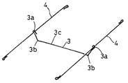
メイン部エンドワイヤ3は、直線状の本体部3cと、屈曲部3bを介して本体部3cの両端に連設されたフック形状の連結部3aとによって構成されている。このメイン部エンドワイヤ3は、境界部エンドワイヤ4、4と交叉するように配置されるものであり、両端の連結部3aが境界部エンドワイヤ4、4に引掛けられることによりメイン部エンドワイヤ3は境界部エンドワイヤ4、4と連結された状態になる。
屈曲部3bにおいては、本体部3cがパットアセンブリ2のメイン部吊り込み溝2dの底部側に位置するように、両端部がカバーアセンブリ1のメイン部1aの裏面方向に向かって適宜の角度で屈曲されている。
これは、次のような機能・効果を有する本発明の最も重要なポイントとなるものである。
【0018】
すなわち、従来のような前記メイン部インサートワイヤに固定しなくとも、連結部3aにより両端が規制された状態でメイン部エンドワイヤ3をメイン部吊り込み溝2d内に押込むのみで、屈曲部3bに発生する曲げ反力により、メイン部吊り込み袋1dをメイン部吊り込み溝2dの底部側に密着するように押圧して吊り込むことができる。
これにより、シートの外観を向上させるため、カバー吊り込み溝部の幅を小さくしてシートの外観を向上させるとともに、カバー吊り込み溝部を深くすることによって、作業性が悪くなるホグリングによる固定作業を極力減らすことができる。
この曲げ反力を有効に活用するため、メイン部エンドワイヤ3は、前記吊り込み時に永久変形しないような充分な剛性を有するばね材などの弾性材料から構成されることが望ましい。
【0019】
境界部吊り込み袋1cの切断部1cxは、図1及び2に示すように、境界部エンドワイヤ4のメイン部のメイン部エンドワイヤ3との連結部3aが露出するように配置されており、これにより外部から境界部エンドワイヤ4とメイン部エンドワイヤ3との連結が容易にできるようになっている。
【0020】
本発明の自動車用シートの組付けは、カバーアセンブリ1をパッドアセンブリ2の表面上に被せた後、両サイドの境界部エンドワイヤ4、4が挿通した境界部吊り込み袋1c、1cをパッドアセンブリ2の境界部吊り込み溝2c、2cに吊り込むとともに、メイン部エンドワイヤ3が挿通したメイン部吊り込み袋1dをパッドアセンブリ2のメイン部吊り込み溝2dに吊り込む。そして、両サイドの境界部エンドワイヤ4、4をパッドアセンブリ1の境界部インサートワイヤ6、6に固定するとともに、メイン部エンドワイヤ3をパッドアセンブリ2のメイン部吊り込み溝2dに押し込む。
境界部エンドワイヤ4、4と境界部インサートワイヤ6、6との固定は、図3に矢印で示すように、Cリング等のホグリング8を境界部エンドワイヤ4、4と対応する境界部インサートワイヤ6、6とに引掛けることにより行う。このホグリング8を用いる場合においては、カバーアセンブリ1の浮き上がりを防止する必要性から境界部エンドワイヤ4、4及び境界部インサートワイヤ6、6の長さ方向の複数箇所を固定しており、図3においては、境界部インサートワイヤ6、6のそれぞれに対して4箇所の合計8箇所を固定している。
【0021】
すなわち、この実施の形態におけるカバーアセンブリ1の境界部の吊り込みは、両サイドの境界部エンドワイヤがそれぞれ2本ずつに分割されメイン部エンドワイヤとも連結されていない従来の構造に対し、境界部エンドワイヤ4、4は単一の1本ずつになって連続しているとともにメイン部エンドワイヤ3の両端の連結部3a、3aとそれぞれ連結されている。なお、ホグリング8により境界部エンドワイヤ4が境界部インサートワイヤ6に複数箇所固定される点は、従来と同様である。
【0022】
以上説明した実施の形態では、前記メイン部吊り込み溝部は1箇所の例を示したが、必要に応じてメイン部吊り込み溝部を2箇所又はそれ以上とすることも自在であることはいうまでもない。
【0023】
【発明の効果】
以上、詳細に説明した本発明によれば、下記のような従来にない優れた効果を奏する。
(1)カバーアセンブリ吊り込み用部品点数が、例えば、従来の工法に対してシートメイン部のメイン部吊り込み溝1個所の場合、エンドワイヤが従来の5本から3本、インサートワイヤが従来の2本から1本、及びホグリングが従来の10点から8点に削減され、吊り込み作業の工数及び重量が削減されるとともにコストダウンすることができる(作業効率及び経済性の向上、軽量化)。
(2)美観向上のための深く、狭い吊り込み溝に対しても、特に、メイン部インサートワイヤ及びそれとのホグリングによる固定を廃止し屈曲形状のメイン部エンドワイヤによる吊り込みによって吊り込み作業が容易化するとともに、ホグリング固定部の集中的な吊り込みがなく、均一な仕上がりが実現できる(作業性及び外観の向上)。
【図面の簡単な説明】
【図1】本発明に係る一実施の形態のメイン部エンドワイヤ仕様による自動車用シートのカバーアセンブリの裏面斜視図である。
【図2】図1のA部の拡大図である。
【図3】本発明に係る一実施の形態のメイン部エンドワイヤ仕様による自動車用シートのカバーリング工法を説明するためのシートの上方(表側)から見た斜視図である。
【図4】本発明に係る一実施の形態のメイン部エンドワイヤ仕様による自動車用シートのエンドワイヤの配置をシートの上方(表側)から見た斜視図である。
【図5】従来の吊り込みワイヤ仕様による自動車用シートのカバーリング工法を説明するためのシートの上方(表側)から見た斜視図である。
【図6】従来の吊り込みワイヤ仕様による自動車用シートのエンドワイヤの配置をシートの上方(表側)から見た斜視図である。
【符号の説明】
1、11 カバーアセンブリ
1a、2a、11a、12a サイド部
1b、2b、11b、12b メイン部
1c、11c 境界部吊り込み袋
1d、11d メイン部吊り込み袋
2、12 パッドアセンブリ
3 メイン部エンドワイヤ
3a 連結部
3b 屈曲部
3c 本体部
4、14、15 境界部エンドワイヤ
6、16 境界部インサートワイヤ
8、18 ホグリング
13 メイン部エンドワイヤ
17 メイン部インサートワイヤ[0001]
BACKGROUND OF THE INVENTION
The present invention relates to an automotive seat in which the seat is covered by a cover assembly.
[0002]
[Prior art]
Conventional automobile seats such as a front seat have a bank-like shape in which the side portions are somewhat higher from both sides of the main portion of the middle portion, and the covering is a hanging wire specification as shown in FIGS. Has become the mainstream. In this case, the cover assembly 11 in which the
In this vehicle seat, since the bank-shaped side portion is higher than the main portion, the boundary portion (concave shape) between the
[0003]
That is, FIG. 5 is a perspective view seen from the upper side (front side) of the seat for explaining the conventional method of covering a vehicle seat, and FIG. 6 is a view of the arrangement of the end wires seen from the upper side (front side) of the seat. It is a perspective view.
Boundary
One boundary portion insert
[0004]
On the other hand, on the back surface of the cover assembly 11, boundary
The boundary
[0005]
The boundary
The
On the other hand, the main
[0006]
The assembly of the automobile seat is carried out by placing the cover assembly 11 on the surface of the
These fixings are performed by hooking a
[0007]
[Problems to be solved by the invention]
Such conventional techniques have the following problems.
In order to prevent the cover assembly at the boundary portion (concave shape) between the main portion and the side portion of the seat from floating from the pad assembly, a complicated configuration as described above is required.
Recently, in order to improve the appearance of the seat, there is a tendency that the bank portion is high and the cover hanging groove portion is deepened (deep hanging) and the hanging groove width is reduced. Workability is getting worse.
As described above, there are problems of cost and weight increase due to the large number of complicated component parts for suspension and a large number of the suspension work steps.
[0008]
In order to solve these problems, an object of the present invention is to reduce the number of components for suspension and the number of man-hours for suspension by a simple mechanism, and the seat cover assembly is closely attached along the shape of the pad assembly. An object of the present invention is to provide a car seat that is covered and has a good appearance.
[0009]
[Means for Solving the Problems]
In the automobile seat according to the present invention , side portions are continuously provided on both sides of the main portion via the boundary portion hanging groove, and a main portion hanging groove intersecting with the boundary portion hanging groove is formed in the main portion. A pad assembly, a boundary part suspending bag suspended in the boundary part suspending groove and a main part suspension bag suspended in the main part suspending groove, and covering a surface of the pad assembly; A boundary part insert wire embedded along the bottom of the boundary part suspension groove, a boundary part end wire inserted into the boundary part suspension bag and fixed to the boundary part insertion wire, and the main part suspension A body portion that is inserted through the bag and extends horizontally so as to be located at the bottom portion thereof, and a bent portion that is inclined toward the surface direction of the cover assembly, and both ends thereof, Characterized in that both end portions and a main portion end wires incorporated hanging by the reaction force of the bent portion in the groove hanging main part in a state of being connected to the boundary end wire.
[0012]
DETAILED DESCRIPTION OF THE INVENTION
Hereinafter, a preferred embodiment of the present invention will be described in detail with reference to the accompanying drawings.
FIG. 1 is a perspective view of the back surface of a cover assembly for an automobile seat according to an embodiment of the present invention, and FIG. 2 is an enlarged view of a portion A in FIG.
FIG. 3 is a perspective view seen from above (front side) of the seat for explaining the covering method of the seat for automobiles of the present invention, and FIG. 4 shows the arrangement of the end wires of the seat for automobiles of the present invention. It is the perspective view seen from the upper side (front side).
[0013]
The automotive seat according to one embodiment of the present invention shown in FIGS. 1 to 4 has a covering wire specification substantially the same as that of the conventional seat except for the configuration of the main portion suspension groove portion of the main portion of the seat. Constructed by construction method. That is, an automobile seat composed of a side portion that has a somewhat higher bank shape on both sides and a main portion in the middle thereof pads the
[0014]
Boundary
One boundary
[0015]
On the other hand, on the back surface of the
The boundary
The
[0016]
The
On the other hand, the main
[0017]
The main
In the
This is the most important point of the present invention having the following functions and effects.
[0018]
That is, even if it is not fixed to the main part insert wire as in the prior art, the
As a result, in order to improve the appearance of the seat, the width of the cover suspending groove is reduced to improve the appearance of the seat, and by deepening the cover suspending groove, the fixing work by hog ring that makes workability worsen as much as possible. Can be reduced.
In order to effectively utilize this bending reaction force, the main
[0019]
As shown in FIGS. 1 and 2, the cutting portion 1cx of the boundary
[0020]
In the assembly of the automobile seat of the present invention, after the
The
[0021]
That is, the suspension of the boundary portion of the
[0022]
In the embodiment described above, the example of the main part hanging groove part is shown as one example, but it goes without saying that the main part hanging groove part can be freely provided at two places or more as needed. Nor.
[0023]
【The invention's effect】
As described above, according to the present invention described in detail, the following excellent effects are obtained.
(1) When the number of parts for hanging the cover assembly is, for example, one main portion hanging groove of the seat main portion with respect to the conventional construction method, the end wire is five to three conventional, and the insert wire is conventional. 2 to 1 and hog ring are reduced from 10 points to 8 points, and the man-hour and weight of the lifting work can be reduced and the cost can be reduced (improvement of work efficiency and economy, light weight). .
(2) Even for deep and narrow suspending grooves for improving aesthetics, the main part insert wire and hog ring fixing to it are abolished, and it is easy to suspend by hanging with a bent main part end wire. In addition, there is no intensive suspension of the hog ring fixing part and a uniform finish can be realized (improvement in workability and appearance).
[Brief description of the drawings]
FIG. 1 is a rear perspective view of a cover assembly for an automobile seat according to an end wire specification of a main part according to an embodiment of the present invention.
FIG. 2 is an enlarged view of part A in FIG.
FIG. 3 is a perspective view seen from the upper side (front side) of the seat for explaining the covering method of the automobile seat according to the main part end wire specification of the embodiment according to the present invention.
FIG. 4 is a perspective view of the arrangement of the end wire of the automobile seat according to the main part end wire specification according to the embodiment of the present invention, as viewed from above (front side) of the seat.
FIG. 5 is a perspective view seen from above (front side) of a seat for explaining a covering method for a seat for automobiles according to a conventional hanging wire specification.
FIG. 6 is a perspective view of the arrangement of end wires of an automobile seat according to a conventional hanging wire specification as viewed from above (front side) of the seat.
[Explanation of symbols]
DESCRIPTION OF
Claims (1)
前記境界部吊り込み溝に吊り込まれる境界部吊り込み袋及びメイン部吊り込み溝内に吊り込まれるメイン部吊り込み袋が設けられ、前記パッドアセンブリの表面を覆うカバーアセンブリと、
前記境界部吊り込み溝の底部に沿って埋設された境界部インサートワイヤと、前記境界部吊り込み袋内に挿通され、境界部インサートワイヤに固定される境界部エンドワイヤと、
前記メイン部吊り込み袋に挿通され、その底部に位置するように水平に伸びる本体部と両端部が前記カバーアセンブリの表面方向に向かって傾斜した屈曲部を有し、前記両端部が前記境界部エンドワイヤに連結された状態で前記メイン部吊り込み溝に前記屈曲部の反力で吊り込まれるメイン部エンドワイヤとを備えていることを特徴とする自動車用シート。A pad assembly in which side portions are continuously provided on both sides of the main portion via the boundary portion hanging groove, and a main portion hanging groove intersecting with the boundary portion hanging groove is formed in the main portion,
A cover assembly for covering the surface of the pad assembly, provided with a boundary portion suspension bag suspended in the boundary portion suspension groove and a main portion suspension bag suspended in the main portion suspension groove;
A boundary portion insert wire embedded along the bottom of the boundary portion suspension groove, a boundary portion end wire inserted into the boundary portion suspension bag and fixed to the boundary portion insertion wire;
A main body part that is inserted into the main part suspension bag and extends horizontally so as to be located at the bottom part thereof, and a bent part that is inclined toward the surface direction of the cover assembly, and the both end parts are the boundary part An automobile seat , comprising: a main part end wire that is suspended in the main part hanging groove by a reaction force of the bent part in a state of being connected to an end wire.
Priority Applications (2)
| Application Number | Priority Date | Filing Date | Title |
|---|---|---|---|
| JP2002199132A JP3735681B2 (en) | 2002-07-08 | 2002-07-08 | Automotive seat |
| US10/614,130 US7017997B2 (en) | 2002-07-08 | 2003-07-08 | Seat |
Applications Claiming Priority (1)
| Application Number | Priority Date | Filing Date | Title |
|---|---|---|---|
| JP2002199132A JP3735681B2 (en) | 2002-07-08 | 2002-07-08 | Automotive seat |
Publications (2)
| Publication Number | Publication Date |
|---|---|
| JP2004041252A JP2004041252A (en) | 2004-02-12 |
| JP3735681B2 true JP3735681B2 (en) | 2006-01-18 |
Family
ID=31706392
Family Applications (1)
| Application Number | Title | Priority Date | Filing Date |
|---|---|---|---|
| JP2002199132A Expired - Fee Related JP3735681B2 (en) | 2002-07-08 | 2002-07-08 | Automotive seat |
Country Status (2)
| Country | Link |
|---|---|
| US (1) | US7017997B2 (en) |
| JP (1) | JP3735681B2 (en) |
Families Citing this family (19)
| Publication number | Priority date | Publication date | Assignee | Title |
|---|---|---|---|---|
| US7946649B2 (en) * | 2007-10-01 | 2011-05-24 | Lear Corporation | Vehicle seat assembly having layered seating system with attachment member |
| DE102010039006A1 (en) * | 2010-08-06 | 2012-02-09 | Bayerische Motoren Werke Aktiengesellschaft | Joint assembly for dunnage rod in vehicle seat, has multiple connection regions, where multiple dunnage rods are connected together by connecting elements |
| JP5578019B2 (en) * | 2010-10-25 | 2014-08-27 | トヨタ紡織株式会社 | Vehicle seat pad and method of manufacturing the same |
| DE102011009773A1 (en) * | 2011-01-29 | 2012-08-16 | Volkswagen Aktiengesellschaft | Removable cover for, e.g. rear seat of vehicle such as motor vehicle, has cushion main portion including a portion comprising trenches which are anchored through fastening elements |
| JP5782906B2 (en) | 2011-08-04 | 2015-09-24 | トヨタ紡織株式会社 | Vehicle seat |
| JP5867295B2 (en) * | 2012-05-30 | 2016-02-24 | トヨタ紡織株式会社 | Vehicle seat |
| JP2014000323A (en) * | 2012-06-20 | 2014-01-09 | Sansho Kk | Seat cover attachment structure, seat cover attachment method, and seat cover attachment tool |
| JP2014000322A (en) * | 2012-06-20 | 2014-01-09 | Sansho Kk | Seat cover attachment structure, seat cover attachment method, and seat cover attachment tool |
| FR3007702B1 (en) * | 2013-06-28 | 2016-02-26 | Renault Sas | ELEMENTS OF SEAT OF AUTOMOTIVE AND SEAT EQUIPPED WITH SUCH A ELEMENT |
| JP6703809B2 (en) * | 2015-04-24 | 2020-06-03 | 株式会社タチエス | Seat suspension structure and seat trim cover suspension method |
| DE102016205472A1 (en) * | 2016-04-01 | 2017-10-05 | Ford Global Technologies, Llc | Upholstery element for a vehicle seat |
| US11547217B1 (en) * | 2017-01-31 | 2023-01-10 | Don Ayres | Mattress assembly with segmented border wires |
| JP6761768B2 (en) * | 2017-02-28 | 2020-09-30 | 株式会社ジェイエスピー | Vehicle seat cushion core material |
| US10532675B2 (en) * | 2018-05-31 | 2020-01-14 | GM Global Technology Operations LLC | Vehicle seat trim cover with integrally knitted attachment features |
| US10808336B2 (en) | 2018-05-31 | 2020-10-20 | GM Global Technology Operations LLC | Vehicle seat trim covers with knitted attachment structures formed with heat-activated yarns |
| US10843600B2 (en) | 2018-07-12 | 2020-11-24 | GM Global Technology Operations LLC | Vehicle seat trim covers including integrally-knit backing materials and methods of manufacturing vehicle seat trim covers |
| JP7362095B2 (en) * | 2018-11-21 | 2023-10-17 | デルタ工業株式会社 | sheet |
| CN110524776B (en) * | 2019-08-30 | 2022-06-21 | 延锋国际座椅系统有限公司 | Hanging structure for seat foaming body |
| CN116923216A (en) | 2022-04-08 | 2023-10-24 | 李尔公司 | Backing strap secured to concave seat back with tie strap |
Family Cites Families (14)
| Publication number | Priority date | Publication date | Assignee | Title |
|---|---|---|---|---|
| US3630572A (en) * | 1969-09-23 | 1971-12-28 | Lear Siegler Inc | Seat assembly |
| US3649974A (en) * | 1969-12-15 | 1972-03-21 | Universal Oil Prod Co | Vehicle seat |
| US3632164A (en) * | 1970-04-02 | 1972-01-04 | Universal Oil Prod Co | Vehicle seat having an improved seat cover attachment system |
| US3961823A (en) * | 1974-09-09 | 1976-06-08 | General Motors Corporation | Vehicle seat bolster wire assembly |
| DE2912461C2 (en) * | 1979-03-29 | 1985-04-11 | Bayerische Motoren Werke AG, 8000 München | Seat, in particular a motor vehicle seat, with an upholstery cover provided with upholstery pipes and fastening tabs, and a method for attaching the fastening tabs for adjacent pipes |
| US4317591A (en) * | 1980-05-27 | 1982-03-02 | General Motors Corporation | Vehicle seat bolster wire assembly |
| US4337931A (en) * | 1980-08-25 | 1982-07-06 | Flex-O-Lators, Inc. | Spring base for upholstered seating |
| SE445818B (en) * | 1984-02-23 | 1986-07-21 | Tachikawa Spring Co | FORDONSSETE |
| JPH035316Y2 (en) * | 1985-08-09 | 1991-02-12 | ||
| IT210581Z2 (en) * | 1987-02-20 | 1988-12-30 | Fiat Auto Spa | COMPLEX FOR ANCHORING A COVERING TO A PADDING OF A VEHICLE SEAT |
| FR2730198B1 (en) * | 1995-02-08 | 1997-04-11 | Faure Bertrand Equipements Sa | HEADDRESS FOR VEHICLE SEAT BACKREST AND SEAT INCLUDING SUCH A HEADDRESS |
| EP0959731B1 (en) * | 1995-11-02 | 2002-08-28 | F.S. Fehrer GmbH & Co. KG. | Foam moulding with an anchoring element buried in the foam |
| JP3335849B2 (en) * | 1996-09-03 | 2002-10-21 | トヨタ自動車株式会社 | Seat structure with side airbag device |
| DE29804603U1 (en) * | 1998-03-14 | 1999-07-15 | Tillner, Thomas, 49205 Hasbergen | Locking element for a pull-in rod for the profile-forming connection of upholstery material in upholstered furniture and the like. Upholstery parts |
-
2002
- 2002-07-08 JP JP2002199132A patent/JP3735681B2/en not_active Expired - Fee Related
-
2003
- 2003-07-08 US US10/614,130 patent/US7017997B2/en not_active Expired - Fee Related
Also Published As
| Publication number | Publication date |
|---|---|
| US20050173964A1 (en) | 2005-08-11 |
| JP2004041252A (en) | 2004-02-12 |
| US7017997B2 (en) | 2006-03-28 |
Similar Documents
| Publication | Publication Date | Title |
|---|---|---|
| JP3735681B2 (en) | Automotive seat | |
| JP3575007B2 (en) | Vehicle seat | |
| EP1283157A3 (en) | Snowmobile | |
| USD500623S1 (en) | Car seat cover | |
| CN107264636A (en) | Front enclosure upper cover plate ornamental parts | |
| GR1004682B (en) | Vehicle body cover structure in motorcycle | |
| JP4273752B2 (en) | Seat heater and automobile seat equipped with the same | |
| JPH05293023A (en) | Heater unit | |
| USD508807S1 (en) | Attachable pocket | |
| USD582065S1 (en) | Headlamp | |
| KR200173887Y1 (en) | Hanger for automobile | |
| JP3874647B2 (en) | Motorcycle seat and method for manufacturing the same | |
| JP4008563B2 (en) | Pocket structure for vehicle interior | |
| KR200143802Y1 (en) | Roof panel support of a bus | |
| JPH0228987Y2 (en) | ||
| JP3028483U (en) | slacks | |
| JPS5937078Y2 (en) | vehicle seat | |
| JP3377030B2 (en) | Sun visor | |
| JP2002085186A (en) | Seat, cushion, frame | |
| JP3023505U (en) | Shape retention structure for soft sheet materials | |
| JP3106458B2 (en) | Structure of pulling part of skin material of vehicle seat | |
| JP2002337587A (en) | Seat for automobile | |
| KR200270453Y1 (en) | hanger For Automobile | |
| JPS6335013Y2 (en) | ||
| KR970006239Y1 (en) | Multi Purpose Clamp |
Legal Events
| Date | Code | Title | Description |
|---|---|---|---|
| A977 | Report on retrieval |
Free format text: JAPANESE INTERMEDIATE CODE: A971007 Effective date: 20050315 |
|
| A131 | Notification of reasons for refusal |
Free format text: JAPANESE INTERMEDIATE CODE: A131 Effective date: 20050426 |
|
| A521 | Request for written amendment filed |
Free format text: JAPANESE INTERMEDIATE CODE: A523 Effective date: 20050627 |
|
| TRDD | Decision of grant or rejection written | ||
| A01 | Written decision to grant a patent or to grant a registration (utility model) |
Free format text: JAPANESE INTERMEDIATE CODE: A01 Effective date: 20050927 |
|
| A61 | First payment of annual fees (during grant procedure) |
Free format text: JAPANESE INTERMEDIATE CODE: A61 Effective date: 20050930 |
|
| R150 | Certificate of patent or registration of utility model |
Free format text: JAPANESE INTERMEDIATE CODE: R150 |
|
| FPAY | Renewal fee payment (event date is renewal date of database) |
Free format text: PAYMENT UNTIL: 20091104 Year of fee payment: 4 |
|
| FPAY | Renewal fee payment (event date is renewal date of database) |
Free format text: PAYMENT UNTIL: 20091104 Year of fee payment: 4 |
|
| S533 | Written request for registration of change of name |
Free format text: JAPANESE INTERMEDIATE CODE: R313533 |
|
| FPAY | Renewal fee payment (event date is renewal date of database) |
Free format text: PAYMENT UNTIL: 20091104 Year of fee payment: 4 |
|
| R350 | Written notification of registration of transfer |
Free format text: JAPANESE INTERMEDIATE CODE: R350 |
|
| FPAY | Renewal fee payment (event date is renewal date of database) |
Free format text: PAYMENT UNTIL: 20091104 Year of fee payment: 4 |
|
| FPAY | Renewal fee payment (event date is renewal date of database) |
Free format text: PAYMENT UNTIL: 20101104 Year of fee payment: 5 |
|
| FPAY | Renewal fee payment (event date is renewal date of database) |
Free format text: PAYMENT UNTIL: 20111104 Year of fee payment: 6 |
|
| FPAY | Renewal fee payment (event date is renewal date of database) |
Free format text: PAYMENT UNTIL: 20121104 Year of fee payment: 7 |
|
| FPAY | Renewal fee payment (event date is renewal date of database) |
Free format text: PAYMENT UNTIL: 20121104 Year of fee payment: 7 |
|
| FPAY | Renewal fee payment (event date is renewal date of database) |
Free format text: PAYMENT UNTIL: 20131104 Year of fee payment: 8 |
|
| R250 | Receipt of annual fees |
Free format text: JAPANESE INTERMEDIATE CODE: R250 |
|
| LAPS | Cancellation because of no payment of annual fees |