JP3731282B2 - Steering control device for work vehicle - Google Patents
Steering control device for work vehicle Download PDFInfo
- Publication number
- JP3731282B2 JP3731282B2 JP06833397A JP6833397A JP3731282B2 JP 3731282 B2 JP3731282 B2 JP 3731282B2 JP 06833397 A JP06833397 A JP 06833397A JP 6833397 A JP6833397 A JP 6833397A JP 3731282 B2 JP3731282 B2 JP 3731282B2
- Authority
- JP
- Japan
- Prior art keywords
- steering
- control valve
- unit
- speed
- steering wheel
- Prior art date
- Legal status (The legal status is an assumption and is not a legal conclusion. Google has not performed a legal analysis and makes no representation as to the accuracy of the status listed.)
- Expired - Fee Related
Links
Images


Landscapes
- Power Steering Mechanism (AREA)
Description
【0001】
【発明の属する技術分野】
この発明は、トラクタや田植機の農業用の作業車両や、フォークリフト、ブルトーザ等の運搬用、建設用の作業車両に関し、特に操向操作部の操作量に対し操向輪の作動量を変更可能な操向装置を有するものに関する。
【0002】
【従来の技術、及びその課題】
従来、作業車両には、作業中の旋回や操向を容易に行うために操向操作部の操作量に対し操向輪の作動量を変更可能な操向装置を有するものがあった。例えば、特開平8−26126号公報には圃場での旋回時に、ステアリングハンドルの操向量に対して前輪の切れ角量を大きくする移動農機の旋回装置が示されている。
【0003】
上記公報に示されている旋回装置は、車体の前輪を操向するパワーステアリングシリンダへの油の流入経路を、油圧ポンプから操向ハンドルの操作方向に応じて圧油を流出する操向ユニットを介して供給する第一の経路と、同油圧ポンプからこの操向ユニットを介さないで直接前記シリンダへ供給する第二の経路とを並列して設けた構成とし、切替制御弁により前記二つの回路を択一式に選択する構成としている。そして、この切替制御弁を、前輪の切角が一定角度を超えると、前記流入経路を前記第一の回路から第二の回路へ切り替わる構成とし、ステアリングハンドルの操向量に対する前輪の切れ角量を大きく変更している。
【0004】
しかしながら、上記旋回装置の油圧回路の構成には、旋回制御の作動時や何らかのアクシデントで切替制御弁が切り替わった状態で戻らなくなる恐れがあり、このような場合には、オペレータのハンドル操作が前輪へ伝達されないためオペレータの所望とする方向へ車両を操向できないという課題があった。
【0005】
【課題を解決するための手段】
この発明は、以上のような課題を解消するために、次のような技術手段を講じた。
即ち、操向操作部(1)の操作量に対し操向輪(2)の作動量を変更可能な操向装置(3)を有する作業車両において、油圧ポンプ(8)から送り出される圧油を回路上手側から順に、前記操向操作部(1)の操作方向に応じて前記圧油を流出する操向ユニット(4)と、前記操向ユニット(4)から流出された圧油の一部を他の回路(5)へ分岐する状態、若しくは同圧油の全部を連通する状態に切り替えて油の流量を調整可能な切替制御弁(6)とを通じて、前記操向輪(2)を操向する油圧アクチュエータ(7)へ送り込む構成とすると共に、
前記車両には、エンジン(12)の出力回転数を検出するエンジン回転センサ(48)と、走行用変速位置を検出する変速スイッチ(31)と、前記操向輪(2)の操向角を検出する操向輪切角センサ(22)とを設け、
前記センサにより、エンジン回転数が一定値以上の状態で且つ走行用変速位置が所定の低速位置に設定された状態が検出され、更に前記操向輪(2)が中立付近で一定値以上の操作速度で操作されたときに、前記切替制御弁(6)を切り替えて操向操作部(1)の操作量に対し操向輪(2)の作動量を大きく変更する制御部(21)を備えたことを特徴とする作業車両の操向制御装置とした。
【0006】
【発明の作用効果】
以上のように構成した作業車両の操向制御装置では、操向ユニット4と、切替制御弁6とを油圧回路において直列に設け、切替制御弁6にて、通常時は、圧油の一部を他の回路5へ分岐する状態として油圧アクチュエータ7による操向輪2の作動量を小さくし、急旋回時等には同圧油の全部を連通する状態として油圧アクチュエータ7による操向輪2の作動量を大きく変更することができるので、操向操作に係る労力の小力化を図ることができる上、万一切替制御弁6が故障しても常時オペレータの操向操作が油圧アクチュエータ7へ伝達可能であるので作業車両を安全に操向することができる。
特にこの作業車両の操向制御装置では、操向ユニット4へ流入される圧油が一定であるため、切替制御弁6の状態に関わらずオペレータの操向操作力を補助する油圧力が一定に保たれ、操向操作部1の操作性が良い。
またこの作業車両の操向制御装置は、エンジン回転数が一定値以上の状態で且つ走行用変速位置が所定の低速位置に設定された状態が検出されたときに作動可能とする構成、即ち車両の路上走行時には同制御の作動は牽制されるので、前記同様、車両の安全性が良い。
【0007】
【発明の実施の形態】
以下、この発明の実施の形態を作業車両である農用トラクタ(以下、トラクタ10)について説明する。
トラクタ10は、機体前部のボンネット11内部に設けたエンジン12の回転動力を、このエンジン12後方に設けたミッションケース13内の変速装置(主変速14、副変速15)により適宜変速してその動力を前輪2,2、或いは前後輪2,2,16,16に伝達して走行する構成となっている。
【0008】
前記ボンネット11の後部には、ハンドルポスト17を設けこの側方にアクセルレバー18を設け、同ポスト17の上部に操向操作部であるステアリングハンドル1を突出して設けている。そして、このステアリングハンドル1の回転操作により後述する操向装置であるパワーステアリング装置3を介して前記前輪2,2を操向する構成となっている。また、ハンドルポスト17の下方には、左右夫々の後輪16,16を制動するブレーキペダル19,19を設けている。左右夫々のブレーキペダル19の回動基部には、この踏み込み操作量を検出する手段であるブレーキセンサ20を設け、この踏み込み角度を検出し、操縦席25下方に設けた制御部であるコントローラ21へ信号を送信する構成となっている。
【0009】
トラクタ10の操縦席25の近傍について説明すると、この操縦席25の側方には、旋回時の前輪1,1の作動量を変更する旋回制御の作動を入り切りする制御入切スイッチ26と、走行用変速レバー27と、作業機28の高さを変更するポジションレバー19を設けている。また、車体後部のPTO軸34の回転を正逆、或いは停止を選択するPTO入切スイッチ30を設けている。前記変速レバー27の回動基部には、変速位置スイッチ31を設け、同レバー27が高速位置へ変速されるとオンする構成となっている。また、ポジションレバー19の回動基部には、この操作角度を検出するポテンショメータ32を設け、前記変速スイッチ31とともにこの検出信号をコントローラ21へ送信する構成となっている。
【0010】
トラクタ10の後部の構成について説明する。前記ミッションケース13の後上部にはシリンダーケース35を設けている。このシリンダーケース35には作業機昇降用の油圧シリンダ36を内蔵し、この油圧シリンダ36のピストン伸縮によりケース35の左右に支持したリフトアーム37,37を上下回動する構成となっている。そして、この片側のリフトアーム37の回動基部には、リフトアーム角センサ38を設け、作業機28の昇降位置を間接的に検出する構成となっている。これにより、前記ポジションレバー29の操作角度に応じて、リフトアーム37の設定角度が一致するように油圧シリンダ36のピストンを伸縮する構成となっている。また、ミッションケース13の後部にはトップリンク39と左右ロアリンク40,40とからなる3点リンク機構を設け,このリンク機構後端部に作業機28を連結可能に構成している。図例ではロータリ作業機を連結した構成となっている。
【0011】
トラクタ10の動力伝導構成について、図3に基づいて説明する。
前記エンジン12から出力された回転動力は、主クラッチ45にて断続され、前後進切替装置46へ入力される。また、このエンジン12の出力軸47には、この回転数を検出する手段としてエンジン回転センサ48を設けている。
そして、前後進切替装置46へ入力されたエンジン12の回転動力は、正転或いは逆転に切り替えられて車両の進行方向を変更するようになっており、前記変速レバー27により主変速装置14、副変速装置15で適宜変速されて後輪デフ機構49へ伝達される構成となっている。また、副変速装置15から出力された回転動力は、前輪駆動軸50へも伝達される構成となっている。
【0012】
前記前輪駆動軸50上には、前輪駆動伝達装置51が設けられている。この前記前輪駆動伝達装置51は、等速クラッチ52と倍速クラッチ53とを有し、この両クラッチ52,53は、コントローラ21の指令によって接続する構成となっている。即ち、等速クラッチ52が接続するときには、前輪2,2の周速が後輪16,16の周速と略同速となり、倍速クラッチ53が接続すると、前輪2,2の周速が後輪16,16の周速に対して略2倍となって小回り旋回が可能になっている。また、どちらのクラッチ52,53も接続していない時には、トラクタ10は、後輪2駆状態で走行する構成となっている。そして、前輪駆動伝達装置51の入力側ギヤ54には後輪回転センサ55を設け、出力側ギヤ56には前輪回転センサ57を設けている。そして、走行中一定時間毎に後輪16による2駆状態として、このときの後輪16の回転数と、地面からの突き回りにより回転する前輪2の回転数を検出して比較(前輪回転数/後輪回転数)することによりトラクタ10のスリップ状態を検出する構成となっている。
【0013】
また、前記後輪デフ機構49から左右に出力される後輪駆動軸58には、夫々ブレーキディスク59…を設けている。このブレーキディスク59…は、前記ブレーキペダル19,19とリンク機構を介して左右独立して接続され、このブレーキペダル19,19の踏み込み操作によりディスクが圧着してブレーキがかかる構成となっている。これにより、圃場での作業では、トラクタ10の後輪16を片側だけ制動可能として隣接旋回を容易にしている。
【0014】
トラクタ10のパワーステアリング装置3について図1に基づいて説明する。パワーステアリング装置3は、ステアリングハンドル1の回転操作をステアリング軸60等を介して操向ユニット4に入力している。そして、ステアリング軸60の回転に応じて操向ユニット4内のジロータ62が回転され、油圧ポンプ8の油圧力が前記ステアリングハンドル1の操作力を補助して、操向ユニット4から流出される構成となっている。この操向ユニット4の回路下手側には、油量調整手段である切替制御弁6を設けている。
【0015】
この切替制御弁6は、絞り65,65を有する油室70と絞りを設けない油室71とを有し、通常時にはこの絞り65,65を有する油室70が前記操向ユニット4と操向用の油圧シリンダ7を連通して位置し、また、コントローラ21からの切替指令により絞りを設けない油室71が操向ユニット4へ接続するように構成されている。そして、通常時には、絞り65、65により規制された圧油は、一部を前記主クラッチ45の潤滑油として分流回路5へ逃がされている。また、このコントローラ21より切替指令を受けた時には同制御弁6に流入した全油量を流出する。尚、この切替制御弁6は、この切替指令が停止されると直ちに前記絞り65,65を有する油室70に切り替わるようスプリング72により付勢している。これにより、切替制御弁6やコントローラ21の故障時しても、ステアリングハンドル1を回したときに、前輪2,2が大きく操向されることが無くトラクタ10を安全に操向することができる。
【0016】
また、この切替制御弁6の油圧回路下手側には、チェック弁66を介して前輪2,2を操向する油圧アクチュエータである油圧シリンダ7を接続して設けている。そして、この油圧シリンダ7のピストンを連結ロッド等を介して前輪2,2を回動するナックルアーム67に連結している。このナックルアーム67には、回動角度を検出する前輪切角センサ22を設けている。これによりコントローラ21では、所定時間内の前輪切角度の変化を演算して操向操作速度を検出する構成となっている。尚、符号Tは、ミッションケース13を兼ねる油圧タンクを示し、R…はリリーフ弁を示す。
【0017】
このように油圧ポンプ8から送り出される圧油の伝動上手側から順に、操向ユニット4、切替制御弁6、前輪2,2を操向する油圧シリンダ7と直列して設けたので、切替制御弁6が絞り65,65を設けてない油室71側に切り替わってわっているときには、通常時と比較してステアリングハンドル3の操作量に対して前輪2,2の操向量を大きく変更することができる。また、この切替制御弁6が通常時、或いは切り替わり時でも、ステアリングハンドル1の回転操作が常時前輪2,2へ伝達可能な状態となっているので、トラクタ10が操向不能な状態に陥ることがない。また、前記切替制御弁6が故障してどちらの場合で作動しなくなっても、ステアリングハンドル1を左右どちらに回転しても前輪2の操向量が同じであるので、操向性を損なうことがない。
【0018】
尚、ここでは操向ユニット4の油圧回路下手側に切替制御弁6を設ける構成としたが、この切替制御弁6を操向ユニット4の上手側に設けてもよい。この実施例のように切替制御弁6を下手側に設ける方が、操向ユニット4へ流入される圧油が一定であるため、切替制御弁6の状態に関わらずオペレータの操向操作力を補助する油圧力が一定に保たれトラクタ10の操作性の面からは好ましい。
【0019】
前記旋回制御について説明する。前記コントローラ7は、図4に示されるように各種センサやスイッチの情報を処理するCPUや、この情報を一時記憶するRAMや、この旋回制御プログラム等を設定しているROM等を有する構成となっている。
そして、入力部には、前記制御スイッチ26と、ブレーキセンサ20,20、PTO入切スイッチ30,変速位置スイッチ31,ポジションレバー29のポテンショメータ32,リフトアーム角センサ38、エンジン回転センサ48、前輪回転センサ57,後輪回転センサ55、前輪切角センサ22を接続して設けている。
【0020】
また、出力部には、前記PTO入切スイッチ30のオンオフによって励磁するPTOを正転、及び逆転に切り替える切替制御弁のソレノイド33F,33Rと、作業機昇降用の油圧シリンダ36のピストンを伸長、短縮する比例圧力制御弁のソレノイド41,42と、等速、倍速クラッチを圧着する切替制御弁のソレノイド68,69と、操向ユニット4の圧油量を調整する切替制御弁のソレノイド9を接続して設けている。
【0021】
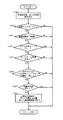
以上のように、構成されたトラクタ10の旋回制御の作用ついて、図5のフローチャートに基づいて説明する。
最初に、トラクタ10の電源系統を「入」にしてエンジン12を始動すると、コントローラ7は、各種スイッチやセンサの設定状態、接続状態、或いは検出状態信号を読み込む(STEP1)。そして、前記前輪切角センサ22によりトラクタ10の操向速度が急旋回と想定される速度以上かどうかを判定する(STEP2)。ここでYESの場合は、次に、制御スイッチ26が入であるか(STEP3)、そして変速位置スイッチ31がオフである、即ち「低速」であるか(STEP4)、エンジン回転センサ48の検出値が一定以上で安定しているか(STEP5)、またスリップの判定が一定範囲以内か(STEP6)を判定する。さらに、前記ブレーキセンサ20の検出を判定して、一方だけの検出値が一定以上か(STEP7)を判定し、これらの判定がすべてYESときに切替制御弁6のソレノイド9へ通電か行われる。そしてこの切替出力は、STEP3〜STEP7の判定がNOになるとオフされ、周期的にこれらの処理が繰り返される。
【0022】
尚、STEP5では、エンジン回転数の変動を検出することで、圃場の凹凸が激しい場所や、路上走行時にこの制御の作動を牽制している。また、STEP6でスリップ状態を検出することで、圃場が極めてぬかるんでいる状態や凍っている状態等で、前輪2,2が急速に切れてトラクタ10が大きくふらつかないように制御の作動を牽制している。
【0023】
図6は、この旋回制御のステアリングハンドル1の切角度(横軸)と前輪切角度(縦軸)の関係を示す図である。ここでは、前輪中立付近の不感帯の位置で前輪操向速度を検出し、前輪操向速度が一定以下の場合は、ステアリングハンドル約±2回転で前輪2,2を左右ロック位置(中立位置から約±60度)まで操向する構成となっている。また、前輪操向速度が一定以上で、且つ切替制御弁6が切り替わる条件が満たされた場合には、ステアリングハンドル約1回転で前輪2,2をロック位置まで操向する構成となっている。
尚、STEP5のエンジン回転数が安定しているかどうかを検出する手段としては、アクセルレバーの回動基部にこの操作角度を検出するアングルセンサを設け、この検出値が一定時間、一定に保たれているかどうかを検出する構成としても良い。
【0024】
また、図7に示されたフローチャートは、前記油量調整手段を常時油路の一部を開放する比例圧力制御弁で構成した場合の例である。ここでは、STEP5にてリフトアーム角度が一定以上かどうかを検出して、作業機28の上昇を検出している。これにより、作業機28が下降したままで制御か作動しこれを大きく横方向へ引きずって破損することを防止している。また、STEP6で前記ブレーキセンサ20,20の角度検出によりブレーキペダル19の踏み込み量を検出してこれに応じて比例圧力制御弁の開放度を制御する構成としている。即ち、オペレータが急速に旋回したいときにはその分片側後輪16のブレーキペダル19を大きく踏み込むのでこの操作量に応じて比例圧力制御弁が油路を開放し、前輪2,2が大きく操向できる状態としている。また、左右両方のブレーキ踏み込みを検出しているときには、路上走行中のブレーキ操作と判定し制御の作動を牽制している。
また、STEP8では、前記操向操作速度に変えて、前輪2,2の切れ角度を検出して、この角度が一定以上になるとステアリングハンドル3の操作量に対し前輪2,2の操向量を増大可能としている。これにより、急速なステアリングハンドル操作が苦手な高齢、或いは女性のオペレータに対してもこの制御が作動して、作業の省力化を図ることができる。
【0025】
尚、STEP4での前記作業機28の上昇操作を検出する手段としては、エンジン回転数を常時検出しこの回転が急激に上昇したとき、即ち作業負荷が無くなったときを検出して作業機28の上昇を間接的に検出してもよい。
尚、特許請求の範囲に実施の形態の構成に対応する部材の符号を付すが、この符号により、この発明をこの実施の形態に限るものではない。
【図面の簡単な説明】
【図1】トラクタの油圧回路の一部。
【図2】トラクタの全体側面図。
【図3】トラクタの動力伝達を示す図。
【図4】コントローラの接続を示すブロック図。
【図5】旋回制御のフローチャート(1)。
【図6】ハンドル切角度と前輪切角度の関係を示すグラフ。
【図7】旋回制御のフローチャート(2)。
【符号の簡単な説明】
1 ステアリングハンドル(操向操作部)
2 前輪(操向輪)
3 パワーステアリング装置(操向装置)
4 操向ユニット
5 分流回路
6 切替制御弁
7 油圧シリンダ(油圧アクチュエータ)
8 油圧ポンプ
12 エンジン
21 コントローラ(制御部)
22 前輪切角センサ
48 エンジン回転センサ [0001]
BACKGROUND OF THE INVENTION
The present invention relates to an agricultural work vehicle for a tractor or a rice transplanter, and a work vehicle for transportation or construction such as a forklift or a bull tosa, and in particular, the operation amount of a steering wheel can be changed with respect to the operation amount of a steering operation unit It relates to what has a steering device.
[0002]
[Prior art and problems]
Conventionally, some work vehicles have a steering device that can change the operation amount of the steering wheel with respect to the operation amount of the steering operation unit in order to easily perform turning and steering during work. For example, Japanese Patent Application Laid-Open No. 8-26126 discloses a turning device for a mobile agricultural machine that increases the turning angle of the front wheel with respect to the steering amount of the steering handle when turning on a farm field.
[0003]
The turning device disclosed in the above publication includes a steering unit that discharges pressure oil from a hydraulic pump in accordance with the operation direction of the steering handle, along the oil inflow path to the power steering cylinder that steers the front wheel of the vehicle body. A first path that is supplied via the hydraulic pump and a second path that is supplied directly from the hydraulic pump to the cylinder without going through the steering unit. Is selected as an alternative set. The switching control valve is configured to switch the inflow path from the first circuit to the second circuit when the front wheel turning angle exceeds a certain angle, and the front wheel turning angle amount relative to the steering wheel steering amount is A major change.
[0004]
However, in the configuration of the hydraulic circuit of the turning device, there is a risk that the turning control valve may not return when the turning control is activated or in a state where the switching control valve is switched due to some accident. There is a problem in that the vehicle cannot be steered in the direction desired by the operator because it is not transmitted.
[0005]
[Means for Solving the Problems]
In order to solve the above problems, the present invention has taken the following technical means.
That is, in a work vehicle having a steering device (3) capable of changing the operation amount of the steering wheel (2) with respect to the operation amount of the steering operation unit (1), the pressure oil sent from the hydraulic pump (8) is discharged. The steering unit (4) that flows out the pressure oil according to the operation direction of the steering operation section (1) in order from the circuit upper side, and a part of the pressure oil that flows out from the steering unit (4) The steering wheel (2) is operated through a switching control valve (6) capable of adjusting the flow rate of the oil by switching to a state where the oil is branched to another circuit (5) or a state where all of the same pressure oil is communicated. The hydraulic actuator (7) is configured to feed to the
The vehicle has an engine rotation sensor (48) for detecting the output rotation speed of the engine (12), a shift switch (31) for detecting a shift position for traveling, and a steering angle of the steering wheel (2). A steering wheel turning angle sensor (22) to detect,
The sensor detects a state in which the engine speed is equal to or higher than a predetermined value and the traveling shift position is set to a predetermined low speed position, and further, the steering wheel (2) is operated to be equal to or higher than a predetermined value near neutral. When operated at a speed, a control unit (21) is provided that switches the switching control valve (6) to greatly change the operation amount of the steering wheel (2) relative to the operation amount of the steering operation unit (1). A steering control device for a work vehicle is provided.
[0006]
[Effects of the invention]
In the steering control device for a work vehicle configured as described above, the
In particular, in this steering control device for a work vehicle, since the pressure oil flowing into the
Further, the steering control device for the work vehicle is configured to be operable when a state in which the engine speed is equal to or greater than a certain value and a state in which the traveling shift position is set to a predetermined low speed position is detected, that is, the vehicle Since the operation of the control is restrained when traveling on the road, the safety of the vehicle is good as described above.
[0007]
DETAILED DESCRIPTION OF THE INVENTION
Hereinafter, an agricultural tractor (hereinafter referred to as a tractor 10) which is a work vehicle will be described as an embodiment of the present invention.
The
[0008]
A handle post 17 is provided at the rear of the bonnet 11, an accelerator lever 18 is provided on the side of the bonnet 11, and a steering handle 1, which is a steering operation unit, protrudes from an upper portion of the post 17. Then, the
[0009]
The vicinity of the
[0010]
The configuration of the rear part of the
[0011]
The power transmission configuration of the
The rotational power output from the
The rotational power of the
[0012]
A front wheel drive transmission device 51 is provided on the front wheel drive shaft 50. The front wheel drive transmission device 51 has a constant speed clutch 52 and a
[0013]
Brake disks 59 are provided on the rear wheel drive shafts 58 output from the rear wheel differential mechanism 49 to the left and right. The brake discs 59 are connected to the
[0014]
The power steering device 3 of the
[0015]
This switching control valve 6 has an
[0016]
Further, a hydraulic cylinder 7, which is a hydraulic actuator that steers the
[0017]
As described above, since the hydraulic oil sent from the
[0018]
Here, the switching control valve 6 is provided on the lower side of the hydraulic circuit of the
[0019]
The turning control will be described. As shown in FIG. 4, the controller 7 has a CPU for processing information of various sensors and switches, a RAM for temporarily storing this information, a ROM for setting this turning control program, and the like. ing.
The input unit includes the
[0020]
In addition, the output part extends
[0021]
The operation of the turning control of the
First, when the
[0022]
In STEP 5, by detecting a change in the engine speed, the operation of this control is restrained when the field is extremely uneven or on the road. In addition, by detecting the slip state in STEP 6, the control operation is controlled so that the
[0023]
FIG. 6 is a diagram showing the relationship between the turning angle (horizontal axis) of the steering handle 1 and the front wheel turning angle (vertical axis) of this turning control. Here, the front wheel steering speed is detected at the position of the dead zone near the front wheel neutral, and when the front wheel steering speed is below a certain level, the
As a means for detecting whether or not the engine speed of STEP 5 is stable, an angle sensor for detecting the operation angle is provided at the rotation base of the accelerator lever, and the detected value is kept constant for a certain time. It is good also as a structure which detects whether it exists.
[0024]
Further, the flowchart shown in FIG. 7 is an example in the case where the oil amount adjusting means is constituted by a proportional pressure control valve that always opens a part of the oil passage. Here, in STEP 5, it is detected whether the lift arm angle is equal to or greater than a certain level, and the rise of the work implement 28 is detected. As a result, the control is operated while the
In
[0025]
As a means for detecting the raising operation of the working
In addition, although the code | symbol of the member corresponding to the structure of embodiment is attached | subjected to a claim, this invention is not limited to this embodiment by this code | symbol.
[Brief description of the drawings]
FIG. 1 is a part of a hydraulic circuit of a tractor.
FIG. 2 is an overall side view of the tractor.
FIG. 3 is a diagram showing power transmission of a tractor.
FIG. 4 is a block diagram showing connection of a controller.
FIG. 5 is a flowchart (1) of turning control.
FIG. 6 is a graph showing the relationship between the steering wheel turning angle and the front wheel cutting angle.
FIG. 7 is a flowchart (2) of turning control.
[Brief description of symbols]
1 Steering handle (steering control unit)
2 Front wheels (steering wheels)
3 Power steering device (steering device)
4 Steering unit
5 Shunt circuit
6 Switching control valve
7 Hydraulic cylinder (hydraulic actuator)
8 Hydraulic pump
12 engine
21 Controller (control unit)
22 Front wheel angle sensor
48 Engine rotation sensor
Claims (1)
前記車両には、エンジン(12)の出力回転数を検出するエンジン回転センサ(48)と、走行用変速位置を検出する変速スイッチ(31)と、前記操向輪(2)の操向角を検出する操向輪切角センサ(22)とを設け、
前記センサにより、エンジン回転数が一定値以上の状態で且つ走行用変速位置が所定の低速位置に設定された状態が検出され、更に前記操向輪(2)が中立付近で一定値以上の操作速度で操作されたときに、前記切替制御弁(6)を切り替えて操向操作部(1)の操作量に対し操向輪(2)の作動量を大きく変更する制御部(21)を備えたことを特徴とする作業車両の操向制御装置。In a work vehicle having a steering device (3) capable of changing the operation amount of the steering wheel (2) with respect to the operation amount of the steering operation unit (1), the hydraulic oil sent from the hydraulic pump (8) In order from the side, the steering unit (4) that discharges the pressure oil according to the operation direction of the steering operation unit (1), and a part of the pressure oil that flows out from the steering unit (4) The steering wheel (2) is steered through a switching control valve (6) capable of adjusting the flow rate of the oil by switching to a state of branching to the circuit (5) of FIG. It is configured to feed to the hydraulic actuator (7) ,
The vehicle has an engine rotation sensor (48) for detecting the output rotation speed of the engine (12), a shift switch (31) for detecting a shift position for traveling, and a steering angle of the steering wheel (2). A steering wheel turning angle sensor (22) to detect,
The sensor detects a state in which the engine speed is equal to or higher than a predetermined value and the traveling shift position is set to a predetermined low speed position, and further, the steering wheel (2) is operated to be equal to or higher than a predetermined value near neutral. When operated at a speed, a control unit (21) is provided that switches the switching control valve (6) to greatly change the operation amount of the steering wheel (2) relative to the operation amount of the steering operation unit (1). A steering control device for a work vehicle.
Priority Applications (2)
| Application Number | Priority Date | Filing Date | Title |
|---|---|---|---|
| JP06833397A JP3731282B2 (en) | 1997-03-21 | 1997-03-21 | Steering control device for work vehicle |
| KR1019970061496A KR100256290B1 (en) | 1997-01-29 | 1997-11-20 | Turning control device of work vehicle |
Applications Claiming Priority (1)
| Application Number | Priority Date | Filing Date | Title |
|---|---|---|---|
| JP06833397A JP3731282B2 (en) | 1997-03-21 | 1997-03-21 | Steering control device for work vehicle |
Publications (2)
| Publication Number | Publication Date |
|---|---|
| JPH10258754A JPH10258754A (en) | 1998-09-29 |
| JP3731282B2 true JP3731282B2 (en) | 2006-01-05 |
Family
ID=13370818
Family Applications (1)
| Application Number | Title | Priority Date | Filing Date |
|---|---|---|---|
| JP06833397A Expired - Fee Related JP3731282B2 (en) | 1997-01-29 | 1997-03-21 | Steering control device for work vehicle |
Country Status (1)
| Country | Link |
|---|---|
| JP (1) | JP3731282B2 (en) |
Families Citing this family (1)
| Publication number | Priority date | Publication date | Assignee | Title |
|---|---|---|---|---|
| KR101439467B1 (en) * | 2007-12-14 | 2014-09-12 | 현대중공업 주식회사 | Electric steering system |
-
1997
- 1997-03-21 JP JP06833397A patent/JP3731282B2/en not_active Expired - Fee Related
Also Published As
| Publication number | Publication date |
|---|---|
| JPH10258754A (en) | 1998-09-29 |
Similar Documents
| Publication | Publication Date | Title |
|---|---|---|
| US8616659B2 (en) | Vehicle steering and braking system | |
| JP3907464B2 (en) | Tractor | |
| JP3876498B2 (en) | Turning control device for work vehicle | |
| JP3731282B2 (en) | Steering control device for work vehicle | |
| JP2002019591A (en) | Hydraulic system for operating at least two functional areas in a vehicle, preferably for steering and shifting of motor vehicles | |
| JPH11222045A (en) | Work vehicle | |
| JP3527091B2 (en) | Agricultural tractor | |
| JP7521409B2 (en) | Work vehicles | |
| JP3692679B2 (en) | Turning control device for work vehicle | |
| KR100256290B1 (en) | Turning control device of work vehicle | |
| JP4135200B2 (en) | Front-wheel drive device for power farm equipment | |
| JP3867337B2 (en) | Steering control device for work vehicle | |
| JP3680451B2 (en) | Automatic transmission control device for work vehicle | |
| JP3918223B2 (en) | Steering control device for tractor | |
| JP3903551B2 (en) | Steering control device for work vehicle | |
| JP3658914B2 (en) | Steering device for work vehicle | |
| JPH04356289A (en) | Controlling device for center of gravity of agricultural ground work vehicle | |
| JP3982037B2 (en) | Front-wheel drive device for power farm equipment | |
| JP4431264B2 (en) | Agricultural tractor steering device | |
| JP3612419B2 (en) | Work vehicle | |
| JP4730551B2 (en) | Work vehicle | |
| JP3618214B2 (en) | Work vehicle | |
| JP2006281869A (en) | Differential lock control device for work vehicle | |
| JP3622217B2 (en) | 4WD lock control device for tractor | |
| JPH10287264A (en) | Work vehicle steering control device |
Legal Events
| Date | Code | Title | Description |
|---|---|---|---|
| A131 | Notification of reasons for refusal |
Free format text: JAPANESE INTERMEDIATE CODE: A131 Effective date: 20040831 |
|
| A521 | Written amendment |
Free format text: JAPANESE INTERMEDIATE CODE: A523 Effective date: 20041022 |
|
| A131 | Notification of reasons for refusal |
Free format text: JAPANESE INTERMEDIATE CODE: A131 Effective date: 20050531 |
|
| A521 | Written amendment |
Free format text: JAPANESE INTERMEDIATE CODE: A523 Effective date: 20050801 |
|
| TRDD | Decision of grant or rejection written | ||
| A01 | Written decision to grant a patent or to grant a registration (utility model) |
Free format text: JAPANESE INTERMEDIATE CODE: A01 Effective date: 20050920 |
|
| A61 | First payment of annual fees (during grant procedure) |
Free format text: JAPANESE INTERMEDIATE CODE: A61 Effective date: 20051003 |
|
| R150 | Certificate of patent or registration of utility model |
Free format text: JAPANESE INTERMEDIATE CODE: R150 |
|
| FPAY | Renewal fee payment (event date is renewal date of database) |
Free format text: PAYMENT UNTIL: 20081021 Year of fee payment: 3 |
|
| FPAY | Renewal fee payment (event date is renewal date of database) |
Free format text: PAYMENT UNTIL: 20111021 Year of fee payment: 6 |
|
| FPAY | Renewal fee payment (event date is renewal date of database) |
Free format text: PAYMENT UNTIL: 20111021 Year of fee payment: 6 |
|
| FPAY | Renewal fee payment (event date is renewal date of database) |
Free format text: PAYMENT UNTIL: 20121021 Year of fee payment: 7 |
|
| FPAY | Renewal fee payment (event date is renewal date of database) |
Free format text: PAYMENT UNTIL: 20121021 Year of fee payment: 7 |
|
| FPAY | Renewal fee payment (event date is renewal date of database) |
Free format text: PAYMENT UNTIL: 20131021 Year of fee payment: 8 |
|
| LAPS | Cancellation because of no payment of annual fees |