JP3716229B2 - Radar equipment - Google Patents
Radar equipment Download PDFInfo
- Publication number
- JP3716229B2 JP3716229B2 JP2002137682A JP2002137682A JP3716229B2 JP 3716229 B2 JP3716229 B2 JP 3716229B2 JP 2002137682 A JP2002137682 A JP 2002137682A JP 2002137682 A JP2002137682 A JP 2002137682A JP 3716229 B2 JP3716229 B2 JP 3716229B2
- Authority
- JP
- Japan
- Prior art keywords
- frequency
- section
- transmission wave
- scanning
- transmission
- Prior art date
- Legal status (The legal status is an assumption and is not a legal conclusion. Google has not performed a legal analysis and makes no representation as to the accuracy of the status listed.)
- Expired - Fee Related
Links
Images


Landscapes
- Radar Systems Or Details Thereof (AREA)
Description
【0001】
【発明の属する技術分野】
本発明は、レーダ装置に係り、更に詳しくは、電波を送信し、その反射波を受信することによって測定対象を検出し、検出された測定対象までの距離や相対速度等を算出するレーダ装置、例えば車載レーダ装置に関するものである。
【0002】
【従来の技術】
図15は、従来のレーダ装置を用いて1つの測定対象についてレーダ測定を行う場合の様子を示した図である。図中の71はレーダ装置、72はレーダ装置の走査範囲、73は測定対象、Rは測定対象までの距離、Vは測定対象との相対速度、θは測定対象の方向を示している。レーダ装置71は車両等の移動体に搭載され、レーダ信号を送受信し、その周波数解析を行うことにより、他の移動体との距離、相対速度、方向を測定するレーダ送受信装置であり、ここでは、測定対象73である車両に後続する車両に搭載されたレーダ装置であるものとする。
【0003】
このレーダ装置71は、送信波に周波数変調を施して送信するとともに、当該送信波の測定対象73における反射波を受信し、この反射波及び送信波のビート信号の周波数に基づいて、測定対象73との距離R、相対速度Vを算出している。また、所定角度からなる走査範囲72内で送信方向を変化させて、測定対象73の方向θを算出している。なお、相対速度Vはレーダ装置71及び測定対象73が離反する方向を正とし、方向θは、レーダ装置71の搭載車両の進行方向に対する角度とする。
【0004】
図16は、図15のレーダ装置71の送受信波形の一例を示した図であり、縦軸に周波数、横軸に時間をとり、送信波(実線)及び受信波(破線)の波形が示されている。送信波には、周波数を時間軸上で線形に増大させる上昇区間81と、時間軸上で線形に減少させる下降区間82とを交互に繰り返す三角波の周波数変調が施されており、その繰返周波数をfm、中心周波数をf0、変調幅を△fとする。なお、繰返周期1/fmに相当する送信波を送信し始めてから、その反射波を受信し終えるまでの時間を送受時間86とする。
【0005】
送信波と受信波との間には、測定対象73までの距離Rに基づく送受信時刻のずれ△tが生じるとともに、測定対象73との相対速度Vに基づく中心周波数のずれ(ドップラーシフト)fbが生じる。このため、送受信信号をミキシングすることによって、上昇区間81では周波数fuのビート信号が得られ、下降区間82では周波数fdのビート信号が得られる。
【0006】
図17は、図16の送受信波に基づいて求められるビート信号のパワースペクトルの一例を示した図であり、縦軸に受信強度、横軸に周波数をとって、上昇区間81及び下降区間82におけるビート信号のスペクトル分布が示されている。図中のfrはfu及びfdの平均値、fpはfu及びfdからfrまでの距離であり、fu,fdはfr及びfpを用いて次式(1),(2)により表される。
【数1】

ここで、frは測定対象73までの距離Rに比例する量、fpは測定対象73の相対速度Vに比例する量であり、fr,fpは光速C、距離R、相対速度Vを用いて次式(3),(4)により表される。
【数2】
上式(1)〜(4)から、レーダ装置71から測定対象73までの距離R、レーダ装置71及び測定対象73の相対速度Vは、それぞれfu,fdの加減算処理を用いて次式のように表される。
【数3】
但し、
【数4】
上式(7)〜(10)に示したように、上昇区間81のビート信号の周波数fuと下降区間82のビート信号の周波数fdが得られれば、測定対象73までの距離R、測定対象73との相対速度Vを求めることができる。
【0011】
ところで、上述したレーダ装置は、測定対象73が1つしか存在しない場合には、その距離R及び相対速度Vを正確に求めることができるが、測定対象73が複数存在する場合は、各々の測定対象との距離R及び相対速度Vを決定することが困難になるという問題があった。
【0012】
図18は、従来のレーダ装置を用いて2つの測定対象についてレーダ測定を行う場合の様子を示した図である。図中の71はレーダ装置、72はレーダ装置の走査範囲、7a,7bは測定対象、Ra,Rbは測定対象までの距離、Va,Vbは各測定対象との相対速度を示している。レーダ装置71は、測定対象7a、7bである2台の車両に後続する車両に搭載されたレーダ装置である。
【0013】
図19は、図17と同様にして、測定対象が2つの場合に求められるビート信号のパワースペクトルの一例を示した図であり、図16に示された変調信号をレーダ装置71から送信した場合が示されている。測定対象が2つの場合、図16に示した三角波の周波数変調の上昇区間81、下降区間82において得られるビート信号の周波数成分は、それぞれ少なくとも測定対象の数(ここでは2)だけ発生する。すなわち、上昇区間81の送信波が2つの測定対象7a,7bに反射して得られたビート信号の周波数成分fua、fubと、下降区間82の送信波が2つの測定対象7a、7bに反射して得られたビート信号の周波数成分fda,fdbが発生することになる。
【0014】
このため、測定対象が2つ存在する場合には、{fua,fda}、{fua,fdb}、{fub,fda}、{fub,fdb}の4つの組み合わせの中から測定対象7a、7bのものとしての正しい2つの組み合わせを選択しなければ、測定対象7a、7bとの距離Ra,Rb及び相対速度Va,Vbとして間違った値を算出してしまうという問題があった。
【0015】
図20は、従来のレーダ装置71の送受信波形の他の例を示した図であり、縦軸に周波数、横軸に時間をとり、送信波(実線)及び受信波(破線)の波形が示されている。この信号波形は、測定対象が2以上の場合における上記課題を解決するために特開平7−20233号公報に開示されたものである。
【0016】
この送信波は、周波数が時間的に変化する上昇区間121及び下降区間122と、周波数が時間的に変化しない無変調区間123とを繰り返す周波数変調が施され、上昇区間121及び下降区間122でのビート信号から得られる複数の周波数成分の組み合わせの中から、無変調区間122のビート信号の周波数成分に基づいて、正しい組み合わせを選択している。以下、この特開平7−20233号公報にかかる従来の技術について、詳しく述べる。
【0017】
2つの測定対象7a,7bが存在する場合、図20に示された上昇区間121、下降区間122における送信波によって得られるビート信号の周波数成分は、図19と同様、上昇区間81に基づく周波数成分fua,fubと、下降区間82に基づく周波数成分fda,fdbからなる。そして、2つの測定対象7a,7bの距離Ra,Rbは、前述したように{fua,fda}{fua,fdb}{fub,fda}{fub,fdb}の4つの組み合わせの中から正しい組み合わせを2つ選択して求めなければならない。
【0018】
また、図20に示された無変調区間123における送信波によって得られるビート信号の周波数成分は、2つの周波数成分fca,fcbからなる。2つの測定対象7a,7bのうち、走行速度の遅い方を7a、走行速度の速い方を7bとする、つまりfca<fcbとすると、それぞれの速度Va,Vbは、次式(11),(12)により求まる。
【数5】
ここで、上昇区間121、下降区間122及び無変調区間123において得られる周波数成分fua,fub,fda,fdb,fca,fcbの間には、次式(13),(14)の関係が成り立つ。
【数6】
すなわち、上昇区間121で得られるビート信号の周波数fuと、下降区間122で得られるビート信号の周波数fdと、無変調区間123で得られるビート信号の周波数fcとの間に、fd−fu=2・fcなる関係が成り立つ時、これら3つの周波数成分が単一の測定対象に属するものと判断できる。
【0021】
従って、測定対象7aに関するビート信号の周波数成分を{fua,fda}、測定対象7bに関するビート信号の周波数成分を{fub,fdb}と決定することができる。測定対象が複数存在する場合でも、先の上昇区間と下降区間のみからなる送信波を利用するレーダ装置と比較して、正しい距離及び相対速度を求めることができる可能性が高くなる。
【0022】
ところで、送信波と受信波をミキサー等によって検波する際に、ビート信号の実数部(以下同相成分と記す)のみの周波数成分を用いれば、レーダを構成するハードウェア要素を少なくすることができるため、小型化、低価格化に有利であり、各種レーダ装置において採用されている。しかしながら、このような構成とした場合、計測すべき周波数の絶対値を得ることはできるが、正負の符号を得ることができなくなってしまう。具体的には、全て非負の周波数範囲に折り返したものとなるので、式(1),(2)は、次式(15),(16)のように変形される。
【数7】
式(15),(16)をfuとfdの符号に応じて場合分けすると、次のように表される。
【数8】
以上のように、ビート信号の実数部のみの周波数成分を用いると、組み合わせの種類(選択肢)が4倍になるため、これらの周波数成分の組み合わせの中から正しい組み合わせを選択することがさらに困難になるという問題があった。
【0025】
特開平10−132925号公報には、このような課題を解決するためのレーダ信号処理方法が開示されている。このレーダ信号処理方法によれば、図20と同様にして、送信波の周波数を上昇区間121、無変調区間123、下降区間122に周波数変調するレーダ装置を用いて、fuとfdの加減算処理を行うだけで測定対象の距離R、相対速度Vを求めることができる。以下、具体的にその内容を説明する。
【0026】
無変調区間123では、ビート信号の周波数fcが測定対象との相対速度Vによって決まるため、fcは相対速度Vを用いて次式(25)のように表される。
【数9】
【0027】
図21は、離反、接近する各測定対象について、レーダ装置71の送受信波形と、そのビート信号の例を示した図であり、(a)には離反する測定対象の場合が示され、(b)には接近する測定対象の場合が示されている。図21から分かるように同相成分のみの検波では、
【数10】
【0028】
さらに、距離R>0なので、距離による周波数成分frは、次式(27)となる。
【数11】
以上の説明により理解される通り、式(25)〜(28)によってfr、fpの大小及び正負関係が得られ、式(7)〜(10)、式(17)〜(24)によって測定対象73の距離R、相対速度Vを求めることができる。
【0030】
図22及び図23のステップ2201〜2215は、上記公報に記載された従来のレーダ信号処理方法を示すフローチャート図であり、測定対象が複数存在する場合におけるレーダ信号処理方法が示されている。このフローチャートに従えば、測定対象が複数存在する場合でも、各測定対象との距離Rmn及び相対速度Vmnを求めることができる。以下、図22及び図23の各ステップについて詳細に説明する。
【0031】
ステップ2201:変調周波数の上昇区間121におけるビート信号の周波数スペクトルから1又は2以上の目標候補を検出し、それぞれの周波数を求める。例えば、受信強度を所定の閾値と比較して当該閾値以上となる周波数スペクトルのピークを検出し、これらの周波数fu(i){i=1,2,…,I}を求める。
【0032】
ステップ2102:周波数の無変調区間123におけるビート信号の周波数スペクトルから1又は2以上の目標候補を検出し、それぞれの周波数を求める。例えば、受信強度を所定の閾値と比較して当該閾値以上となる周波数スペクトルのピークを検出し、これらの周波数fc(k){k=1,2,…,K}を求める。
【0033】
ステップ2203:変調周波数の下降区間122におけるビート信号の周波数スペクトルから1又は2以上の目標候補を検出し、それぞれの周波数を求める。例えば、受信強度を所定の閾値と比較して当該閾値以上となる周波数スペクトルのピークを検出し、これらの周波数fd(j){j=1,2,…,J}を求める。
【0034】
ステップ2204:ステップ2201及びステップ2203で検出された目標候補のスペクトルの周波数fu(i){i=1,2,…,I}とfd(j){j=1,2,…,J}の全ての組み合わせについて、次式(29),(30)に従って、周波数和fsum(i,j)及び周波数差fdif(i,j)を求める。
【数12】
ステップ2205:ステップ2202で検出された各目標候補の周波数fc(k){k=1,2,…,K}を、ステップ2204で求められたfsum(i,j)及びfdif(i,j)と比較し、fc(l)=fsum(m,n)あるいはfc(l)=fdif(m,n)となるfu(m)及びfd(n)を正しい組み合わせとして選択する。
【0036】
ステップ2206:fc(l)がfsum(m,n)と等しいかどうかを判定し、等しければステップ2207へ進み、等しくなければステップ2211へ進む。
【0037】
ステップ2207:fc(l)=fsum(m,n)の場合、まず、距離周波数fr(m,n)をfdif(m,n)とする。
【0038】
ステップ2208:次に、fu(m)とfd(n)の大きさを比較し、fu(m)≧fd(n)であればステップ2209へ進み、fu(m)<fd(n)であればステップ2210へ進む。
【0039】
ステップ2209:速度周波数fp(m,n)をfsum(m,n)としてステップ2215へ進む。
【0040】
ステップ2210:速度周波数fp(m,n)を−fsum(m,n)としてステップ2215へ進む。
【0041】
ステップ2211:一方、fc(l)≠fsum(m,n)の場合、まず、距離周波数fr(m,n)をfsum(m,n)とする。
【0042】
ステップ2212:次に、fu(m)とfd(n)の大きさを比較し、fu(m)≧fd(n)であればステップ2213へ進み、fu(m)<fd(n)であればステップ2214へ進む。
【0043】
ステップ2213:速度周波数fp(m,n)をfdif(m,n)としてステップ2215へ進む。
【0044】
ステップ2214:速度周波数fp(m,n)を−fdif(m,n)としてステップ2215へ進む。
【0045】
ステップ2215:求められたfr(m,n),fp(m,n)に基づいて、式(3),(4)から相対距離Rmnと相対速度Vmnを求める。
【0046】
【発明が解決しようとする課題】
上述した通り、送信波として周波数の上昇区間81及び下降区間82からなる周波数変調波を用いるレーダ装置の場合、測定対象が複数存在する場合に、各々の測定対象との距離及び相対速度を決定することが困難であるという問題があった。
【0047】
この様な問題を解決するため、上記公報(特開平7−20233号、特開平10−132925号)に記載の従来のレーダ装置では、送信波として周波数の上昇区間121、下降区間122及び無変調区間123からなる周波数変調波を用いることにより、複数ある各測定対象との距離R及び相対速度Vを求めている。
【0048】
しかしながら、この様なレーダ装置の場合、上昇区間121及び下降区間122に加え、無変調区間123についても周波数スペクトル解析を行う必要があるため、無変調区間についての演算時間の分だけ、走査中の一方向当たりの測距周期(距離及び相対速度を取得する周期)が長くなってしまうという問題があった。
【0049】
また、上昇区間121、下降区間122及び無変調区間123の各送信波を送信する時の走査方向が異なると、測定対象の整合性が取りにくくなるため、送信波を送信してから受信波を受信するまでの間、送受信方向が同一となるように、走査することを止めるか、あるいは走査の速度を下げることが望ましい。しかしながら、走査することを止めることができる走査の機構系は一般的に複雑かつ高価になってしまうという問題があった。また、走査速度を下げると走査範囲が狭くなるか所定の走査範囲を走査するための走査周期が長くなってしまうという問題があった。
【0050】
さらに、測距周期1/fmを所定時間以下に抑えるために、図20における送受時間126を図16における送受時間86と等しくしようとする場合、図20に示した送信波の中に無変調区間123の分だけ、上昇区間121、下降区間122の時間が上昇区間81、下降区間82の時間に比べて短くなり、FFT(First Fourier Transfer)処理部におけるサンプリング数が少なくなって、距離及び相対速度の測定精度を悪化させてしまうという問題があった。
【0051】
本発明は、上記の事情に鑑みてなされたものであり、測定対象が2以上存在する場合でも各測定対象の距離又は相対速度を測定することができるとともに、走査中の一方向当たりの測距周期の短いレーダ装置を提供することを目的とする。
【0052】
また、本発明は、測定精度の低下、測距周期の増加、機構系の複雑化、高価格化、あるいは走査範囲の狭域化を招くことなく、測定対象が2以上存在する場合でも各測定対象の距離又は相対速度を測定することができるレーダ装置を提供することを目的とする。
【0053】
【課題を解決するための手段】
請求項1に記載の本発明によるレーダ装置は、周波数が時間軸上で増大する周波数上昇区間、周波数が時間軸上で減少する周波数下降区間及び周波数が時間軸上で一定となる周波数無変調区間からなる送信波を生成する周波数変調手段と、生成された送信波を送出するとともに、測定対象による反射波を受信する送受信手段と、送受信手段の送受信方向を所定の走査範囲において繰り返し走査させる走査手段と、送信波及び受信波に基づいて、2以上の各測定対象ごとに距離又は相対速度を求める信号処理手段とを備えたレーダ装置であって、周波数変調手段が、周波数上昇区間、周波数下降区間及び周波数無変調区間のいずれか2つの区間を交互に繰り返す第1の送信波と、残る1つの区間を繰り返す第2の送信波とを生成し、第1の送信波及び第2の送信波が走査周期に同期して切り替えられるように構成される。
【0054】
請求項2に記載の本発明によるレーダ装置は、第1の送信波及び第2の送信波が、走査周期ごとに交互に送出されるように構成される。
【0055】
請求項3に記載の本発明によるレーダ装置は、上記第1の送信波が、周波数上昇区間及び周波数下降区間からなり、上記第2の送信波が周波数無変調区間からなる。
【0056】
請求項4に記載の本発明によるレーダ装置は、周波数変調手段が、周波数上昇区間、周波数下降区間及び周波数無変調区間のいずれか2つの区間を交互に繰り返す第1の送信波と、残る1つの区間及び第1の送信波を構成するいずれか1つの区間を交互に繰り返す第2の送信波とを生成し、第1の送信波及び第2の送信波が走査周期に同期して切り替えられるように構成される。
【0057】
請求項5に記載の本発明によるレーダ装置は、第1の送信波及び第2の送信波が、走査周期ごとに交互に送出されるように構成される。
【0058】
請求項6に記載の本発明によるレーダ装置は、上記第1の送信波が、周波数上昇区間及び周波数下降区間からなり、上記第2の送信波が周波数上昇区間及び周波数無変調区間からなる。
【0059】
請求項7に記載の本発明によるレーダ装置は、上記第1の送信波が、周波数上昇区間及び周波数下降区間からなり、上記第2の送信波が周波数下降区間及び周波数無変調区間からなる。
【0060】
請求項8に記載の本発明によるレーダ装置は、上記第1の送信波が、周波数上昇区間及び周波数無変調区間からなり、上記第2の送信波が周波数下降区間及び周波数無変調区間からなる。
【0061】
請求項9に記載の本発明によるレーダ装置は、送信波を生成する周波数変調手段と、生成された送信波を送出するとともに、測定対象による反射波を受信する送受信手段と、送受信手段の送受信方向を所定の走査範囲において繰り返し走査させる走査手段と、送信波及び受信波によるビート信号を生成するビート信号生成手段と、このビート信号に基づいて、2以上の各測定対象ごとに距離又は相対速度を求める信号処理手段とを備えたレーダ装置であって、周波数変調手段が、周波数が時間軸上で増大する周波数上昇区間、周波数が時間軸上で減少する周波数下降区間及び周波数が時間軸上で一定となる周波数無変調区間のうち2以下の区間を繰り返す第1の送信波と、残りの全ての区間を含む2以下の区間を繰り返す第2の送信波とを生成し、第1の送信波及び第2の送信波が走査周期に同期して切り替えられるように構成される。
【0062】
請求項10に記載の本発明によるレーダ装置は、第1の送信波及び第2の送信波が、走査周期ごとに交互に送出されるように構成される。
【0063】
請求項11に記載の本発明によるレーダ装置は、上記信号処理手段が、走査範囲に含まれる複数の走査方向のそれぞれについて、周波数上昇区間、周波数下降区間及び周波数無変調区間の各ビート周波数から測定対象との距離又は相対速度を求めるように構成される。
【0064】
請求項12に記載の本発明によるレーダ装置は、上記信号処理手段が、周波数上昇区間のビート周波数及び周波数下降区間のビート周波数の各組合わせについて、周波数和及び周波数差の絶対値を求めるステップと、周波数和又は周波数差の絶対値が周波数無変調区間のビート周波数と等しくなる周波数上昇区間のビート周波数及び周波数下降区間のビート周波数の組合わせを選択するステップと、周波数和に基づいて測定目標までの距離を求めるステップと、周波数差に基づいて測定目標との相対速度を求めるステップからなる処理を各走査方向ごとに実行するように構成される。
【0065】
請求項13に記載の本発明によるレーダ装置は、上記ビート信号生成手段が、送信波及び受信波から得られるビート信号の実数部の周波数成分を求め、信号処理手段が、求められたビート周波数に基づいて、測定対象との距離又は相対速度を求めるように構成される。
【0066】
請求項14に記載の本発明によるレーダ装置は、上記信号処理手段が、周波数上昇区間のビート周波数及び周波数下降区間のビート周波数の各組合わせについて、周波数和及び周波数差の絶対値を求めるステップと、周波数和又は周波数差の絶対値が周波数無変調区間のビート周波数と等しくなる周波数上昇区間のビート周波数及び周波数下降区間のビート周波数の組合わせを選択するステップと、周波数和又は周波数差の絶対値のうち周波数無変調区間のビート周波数と異なる値に基づいて、測定目標までの距離を求めるステップと、周波数和又は周波数差の絶対値のうち周波数無変調区間のビート周波数と等しくなる値に基づいて、測定目標との相対速度を求めるステップからなる処理を各走査方向ごとに実行するように構成される。
【0067】
【発明の実施の形態】
実施の形態1.
図1は、本発明の実施の形態1によるレーダ装置の一構成例を示したブロック図である。図中の1はレーダ装置、10は信号処理装置、11は発振器、12はパワーデバイダ、13は送信アンプ、14はサーキュレータ、15aはホーンアンテナ、15bはアンテナ反射鏡、16は受信アンプ、17はミキサー、18はフィルタ、19はアンプ、20はA/D変換器、21はアンテナ走査用モータである。
【0068】
ホーンアンテナ15aは、送受信共用のアンテナであり、アンテナ反射鏡15bは、ホーンアンテナ15aの送受信波を反射して、ホーンアンテナ15aに指向性を持たせている。つまり、ホーンアンテナ15a及びアンテナ反射鏡15bにより指向性アンテナを構成している。アンテナ走査用モータ21は、アンテナ反射鏡15bを回転駆動させるための駆動装置であり、信号処理装置10から出力される走査方向に応じた制御信号に基づいて、アンテナ角度(例えば水平面内におけるアンテナの方位)を制御し、送受信方向を制御している。
【0069】
発振器11は、信号処理装置10からの制御信号に基づいて、周波数変調が施された送信信号を発生させる。発振器11で生成された送信信号は、パワーデバイダ12において2つに分岐され、その一方はミキサー17に入力され、他方は送信アンプ13で増幅された後、サーキュレータ14を経由してホーン15aから放射される。
【0070】
ホーンアンテナ15aから出力された電波は、アンテナ反射鏡15bで反射され、所定の送信方向へ向けて空間に放射される。空間へ出射された電波は測定対象(不図示)で乱反射され、その反射波の一部が、再びアンテナ反射鏡15bにより反射され、ホーンアンテナ15aに入射され受信される。
【0071】
この受信信号は、サーキュレータ14を経由して受信アンプ16で増幅された後、ミキサー17により上記送信信号とミキシングされる。受信信号は、送信信号に対して遅延時間△tを持ってホーンアンテナ15aに入射され、また、測定対象がレーダ装置に対して相対速度を持つ場合、送信信号に対してドップラーシフトfbを持ってホーンアンテナ15aに入力される。
【0072】
このため、ミキサー17において、遅延時間△tとドップラーシフトfbに対応したビート周波数信号が生成される。なお、実施の形態1及び2では、ミキサー17で求められるビート信号の周波数には符号が付されているものとする。
【0073】
生成されたビート周波数信号は、フィルタ18を通過し、アンプ19により増幅されてA/D変換器20、さらには信号処理装置10に入力される。信号処理装置10では、ビート周波数信号の周波数スペクトル解析を行い、この解析結果に基づいて、測定対象までの距離、相対速度が求められる。
【0074】
このレーダ装置は、アンテナ走査用モータ21がアンテナ反射鏡15bを駆動することにより、レーダ装置の送受信方向を所定の走査範囲において繰り返し走査させている。走査範囲は、更に複数の走査方向からなり、レーダ装置1は、各走査方向について、以上の動作を繰り返し行っている。
【0075】
図2は、図1のレーダ装置1の送受信波形の一例を示した図であり、縦軸に周波数、横軸に時間をとり、送信波(実線)及び受信波(破線)の波形が示されている。(a)には、図16と同様、周波数を時間軸上で線形に増大させる上昇区間31と、時間軸上で線形に減少させる下降区間32とを繰返周期1/fmで交互に繰り返す三角波の周波数変調が施された送受信信号が示されている。一方、(b)には、周波数が時間的に変化しない周波数無変調信号が示されている。つまり、周波数無変調区間33のみからなる。発振器11は、信号処理装置10の指示に基づいて、2種類の送信信号、すなわち図6の(a)又は(b)のいずれかの送信信号を生成している。
【0076】
図3は、図1のレーダ装置1の走査方向の一例を示した図である。アンテナ走査用モータ21により駆動されるアンテナ反射鏡15bは、ホーンアンテナ15aを各走査方向40〜44に変化させ、走査範囲40〜44を所定の走査周期で走査している。
【0077】
図4は発振器11により生成される送信波の切替タイミングの一例を示した図である。図2に示した2種類の送信波を生成する発振器11は、同一の走査周期内においては同一の送信波を生成し、走査周期に同期して送信波を切り替えている。図4では、走査周期ごとに送信波を切り替える例が示されている。すなわち、2n回目(n=0,1,2…)の走査周期では、図3の各走査方向40〜44に対して、図2(a)に示された上昇区間31及び下降区間32からなる周波数変調信号が送信される。また、(2n+1)回目の走査周期では、図3の各走査方向40〜44に対して、図2(b)に示された周波数無変調信号が送信される。
【0078】
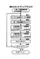
図5のステップ501〜506は、本発明の実施の形態1によるレーダ信号処理方法の一例を示したフローチャートであり、図6〜図8は、それぞれ図5のステップ504〜506の詳細を示したフローチャートである。これらのフローチャートに従えば、一方向当たりの測定周期を長くすることなく、測定対象が複数存在する場合でも、各測定対象との距離Rmn及び相対速度Vmnを求めることができる。以下、図5のフローチャートの各ステップについて詳細に説明する。
【0079】
ステップ501:信号処理装置10は、何番目の走査周期であるのかを認識するためのカウンタScanCntを備え、この走査周期を示すカウンタScanCntをインクリメントして、走査周期ごとの処理を開始する。
【0080】
ステップ502:信号処理装置10は、同一の走査周期中の何番目の走査方向40〜44であるのかを認識するためのカウンタDCntを備え、このカウンタDCntをリセットする。このため、その値はゼロとなり、まず最初の走査方向40を対象として以下の処理が行われる。
【0081】
ステップ503:カウンタScanCntが偶数の時はステップ504に進み、奇数の時は、ステップ505に進む。つまり、ステップ504及びステップ505は、走査周期ごとに交互に実行される。
【0082】
ステップ504:図2(a)に示した上昇・下降変調信号からなる送信波を走査しながら、各走査方向40〜44について、上昇区間におけるビート信号のピーク周波数fuと、下降区間におけるビート信号のピーク周波数fdが求められた後、ステップ506に進む。
【0083】
ステップ505:図2(b)に示した無変調信号からなる送信波を走査しながら、各走査方向40〜44について、ビート信号のピーク周波数fcが求められた後、ステップ506に進む。
【0084】
ステップ506:ステップ504及びステップ505において求められたfu、fd及びfcに基づいて信号処理装置10による演算処理が行われ、各走査方向40〜44について、1又は2以上の測定対象との距離R及び相対速度Vが求められる。その後、再びステップ501に戻る。
【0085】
図6のステップ601〜606は、図5のステップ504(上昇・下降変調信号による走査)の詳細を示したフローチャートであり、上昇・下降変調信号を用いて、各走査方向ごとに上昇区間と下降区間のそれぞれにおけるビート信号のピーク周波数fu、fdを求めるための処理方法が示されている。以下、図6のフローチャートの各ステップについて詳細に説明する。
【0086】
ステップ601:カウンタDCntの値に基づき、アンテナ走査用モータ21がアンテナ反射鏡15bを回転駆動させ、ホーンアンテナ15aによる送受信方向を変化させる。
【0087】
ステップ602:発振器11は、信号処理装置10の指令に基づいて、図2(a)に示した変調周波数の上昇区間31及び周波数下降区間32からなる送信波を生成し、この送信波がホーンアンテナ15aから出力される。
【0088】
ステップ603:1つの走査方向に関して、変調周波数の上昇区間31におけるビート信号の周波数スペクトルから1又は2以上の目標候補を検出し、それぞれの周波数を求める。例えば、受信強度を所定の閾値と比較して当該閾値以上となる周波数スペクトルのピークをI個(Iは1又は2以上)検出し、これらの周波数fu(i、DCnt){i=1,2,3,…,I}を求める。
【0089】
ステップ604:1つの走査方向に関して、変調周波数の下降区間32におけるビート信号の周波数スペクトルから1又は2以上の目標候補を検出し、それぞれの周波数を求める。例えば、受信強度を所定の閾値と比較して当該閾値以上となる周波数スペクトルのピークをJ個(Jは1又は2以上)検出し、これらの周波数fd(j,DCnt){j=1,2,3,…,J}を求める。
【0090】
ステップ605:走査方向を示すカウンタDCntをインクリメントして、次の走査方向41、42,…が処理の対象とされる。
【0091】
ステップ606:カウンタDCntが5未満であればステップ601に戻り、新たな走査方向について同様の動作(ステップ601〜605)を繰り返す。カウンタDCntが5以上であれば、全ての走査方向40〜44について走査が完了しているため、当該処理を終了して図5のステップ506に進む。
【0092】
図7のステップ701〜705は、図5のステップ505(無変調信号による走査)の詳細を示したフローチャートであり、無変調信号を用いて、各走査方向ごとにビート信号のピーク周波数fcを求めるための処理方法が示されている。以下、図7のフローチャートの各ステップについて詳細に説明する。
【0093】
ステップ701:カウンタDCntの値に基づき、アンテナ走査用モータ21がアンテナ反射鏡15bを回転駆動させ、ホーンアンテナ15aによる送受信方向を変化させる。
【0094】
ステップ702:発振器11は、信号処理装置10の指令に基づいて、図2(b)に示した周波数を無変調とした送信波を生成し、この送信波がホーンアンテナ15aから出力される。
【0095】
ステップ703:1つの走査方向に関して、無変調周波数のビート信号の周波数スペクトルから1又は2以上の目標候補を検出し、それぞれの周波数を求める。例えば、受信強度を所定の閾値と比較して当該閾値以上となる周波数スペクトルの1又は2以上のピークをK個(Kは1又は2以上)検出し、これらの周波数fc(k、DCnt){k=1,2,3,…,K}を求める。
【0096】
ステップ704:走査方向を示すカウンタDCntをインクリメントして、次の走査方向41、42,…が処理の対象とされる。
【0097】
ステップ705:カウンタDCntが5未満であればステップ701に戻り、新たな走査方向について同様の動作(ステップ701〜704)を繰り返す。カウンタDCntが5以上であれば全ての走査方向40〜44について走査が完了しているため、当該処理を終了して図5のステップ506に進む。
【0098】
図8のステップ801〜810は、図5のステップ506(演算処理)の詳細を示したフローチャートであり、2以上の測定対象までの距離及び相対速度を各走査方向ごとに求めるための処理方法が示されている。以下、図8のフローチャートの各ステップについて詳細に説明する。
【0099】
ステップ801:走査方向を示すカウンタDCntをリセットして、その値がゼロとなり、まず最初の走査方向40について以下の演算が行われる。
【0100】
ステップ802:図6のステップ603及びステップ604で検出された目標候補のスペクトルの周波数fu(i,DCnt){i=1,2,…,I}とfd(j,DCnt){j=1,2,…,J}について、全てのi,jの組み合わせについて、周波数和fsum(i,j)と周波数差fdif(i,j)を次式(31),(32)により求める。
【数13】
ステップ803:図7のステップ703で検出された目標候補の周波数fc(k,DCnt){k=1,2,…,K}と、ステップ802で求められたfsum(i,j)およびfdif(i,j)を比較して、次式(33)又は(34)を満足するfc(l),fu(m),fd(n)の1又は2以上の組み合わせを正しい組み合わせとして選択する。
【数14】
ステップ804:距離周波数fr(m,n)を周波数和fsum(m,n)とする。
【0103】
ステップ805:fu(m)とfd(n)の大きさを比較し、fu(m)≧fd(n)であればステップ806へ、fu(m)<fd(n)であればステップ807へ進む。
【0104】
ステップ806:速度周波数fp(m,n)を周波数差fdif(m,n)として、ステップ808へ進む。
【0105】
ステップ807:速度周波数fp(m,n)を−fdif(m,n)として、ステップ808へ進む。
【0106】
ステップ808:ステップ806およびステップ807で求められたfr(m,n)およびfp(m,n)から、次式(35),(36)により距離Rmn及び相対速度Vmnが求められる。
【数15】
ステップ809:走査方向を示すカウンタDCntをインクリメントして、次の走査方向41、42,…が処理の対象とされる。
【0108】
ステップ810:カウンタDCntが5未満であればステップ802に戻り、新たな走査方向について同様の動作(ステップ802〜809)を繰り返す。カウンタDCntが5以上であれば全ての走査方向40〜44について走査が完了しているため、当該処理を終了して図5のステップ501に戻る。
【0109】
本実施の形態によるレーダ装置では、変調周波数の上昇区間及び下降区間から構成され無変調区間を有しない図2(a)の送信波と、無変調区間のみで構成される図2(b)の送信波とを各走査周期ごとに切り替えて送信している。そして、走査周期の単位で時間的に前後して得られる、図2(a)の送信波に基づくビート信号の周波数成分fu,fdと、図2(b)の送信波に基づくビート信号の周波数成分fcを用いて、測定対象の距離及び相対速度を算出している。
【0110】
すなわち、従来のレーダ装置のように、変調周波数の上昇区間及び下降区間とともに無変調区間を有する図20に示したような送信波を用いることなく、従来の装置と同様にして、上昇区間、下降区間及び無変調区間におけるビート周波数を用いて測定対象との距離及び相対速度を求めている。
【0111】
これにより、測定対象が2以上存在する場合でも、周波数成分の誤組み合わせを防止して正しく測定することができるとともに、測定精度の低下、測距周期の増加、機構系の複雑化あるいは高価格化、走査範囲の狭域化などの問題を引き起こすことがない。従って、2以上の測定対象が存在する場合でも、各測定対象までの距離及び相対速度を精度よく求めることができる。
【0112】
なお、本実施の形態では、上昇区間及び下降区間からなる送信波信号と、無変調区間のみからなる送信波信号とを走査周期ごとに切り替えて送信する場合について説明したが、本発明はこのような送信波信号の場合に限定されない。つまり、上昇区間、下降区間、無変調区間の3区間を任意に組み合わせて2種類の送信波信号を生成し、走査周期に同期して切り替えて送信すれば、同様の効果を奏することができるため、3区間の組み合わせは他の組み合わせであってもよい。具体的には、上昇区間及び無変調区間からなる送信波信号と、下降区間のみからなる送信波信号とを用いてもよいし、無変調区間及び下降区間からなる送信波信号と、上昇区間のみからなる送信波信号とを用いてもよい。
【0113】
実施の形態2.
本実施の形態における構成及び動作は、実施の形態1の場合と基本的には同じであるが、発振器11によって生成される2種類の送信波が異なる。また、これに伴って信号処理装置10における処理内容が異なる。
【0114】
図9は、図1のレーダ装置1の送受信波形の他の例を示した図であり、縦軸に周波数、横軸に時間をとり、送信波(実線)及び受信波(破線)の波形が示されている。図9(a)には、図2(a)と同様、周波数を時間軸上で線形に増大させる上昇区間31と、時間軸上で線形に減少させる下降区間32とを交互に繰り返す三角波の周波数変調が施された送受信信号が示されている。一方、図9(b)には、周波数を時間軸上で線形に増大させる上昇区間34と、周波数が時間的に変化しない無変調区間33が示されている。発振器11は、信号処理装置10の指示に基づいて、2種類の送信信号、すなわち図9の(a)又は(b)のいずれかの送信信号を生成している。
【0115】
図10は発振器11により生成される送信波の切替タイミングの一例を示した図である。図9に示した2種類の送信波を生成する発振器11は、同一の走査周期内においては同一の送信波を生成し、走査周期に同期して送信波を切り替えている。図10では、走査周期ごとに送信波が切り替えられている。すなわち、2n回目(n=0,1,2…)の走査周期では、各走査方向40〜44に対して、図9(a)に示された上昇区間及び下降区間からなる周波数変調信号が送信される。また、(2n+1)回目の走査周期では、各走査方向40〜44に対して、図9(b)に示された上昇区間及び無変調区間からなる周波数変調信号が送信される。
【0116】
図11のステップ1101〜1106は、本発明の実施の形態2によるレーダ信号処理方法の一例を示したフローチャートであり、図12は、図11のステップ1105(無変調信号による走査)の詳細を示したフローチャートである。図11のフローチャートを図5の場合と比較すれば、ステップ1105のみが異なり、他のステップ1101〜1104及び1106は図5の対応するステップと同じである。以下、図11のフローチャートの各ステップについて詳細に説明する。
【0117】
ステップ1101:信号処理装置10は、何番目の走査周期であるのかを認識するためのカウンタScanCntを備え、この走査周期を示すカウンタScanCntをインクリメントして、走査周期ごとの処理を開始する。
【0118】
ステップ1102:信号処理装置10は、同一の走査周期中の何番目の走査方向40〜44であるのかを認識するためのカウンタDCntを備え、このカウンタDCntをリセットする。このため、その値はゼロとなり、まず最初の走査方向40を対象として以下の処理が行われる。
【0119】
ステップ1103:カウンタScanCntが偶数の時はステップ1104に進み、奇数の時は、ステップ1105に進む。つまり、ステップ1104及びステップ1105は、走査周期ごとに交互に実行される。
【0120】
ステップ1104:図9(a)に示した上昇・下降変調信号からなる送信波を走査しながら、各走査方向40〜44について、上昇区間31におけるビート信号のピーク周波数fuと、下降区間32におけるビート信号のピーク周波数fdが求められた後、ステップ1106に進む。
【0121】
ステップ1105:図9(b)に示した上昇・無変調信号からなる送信波を走査しながら、各走査方向40〜44について、上昇区間34におけるビート信号のピーク周波数fuと、無変調区間33におけるビート信号の周波数fcが求められた後、ステップ1106に進む。
【0122】
ステップ1106:ステップ1104及びステップ1105において求められたfu、fd及びfcに基づいて信号処理装置10による演算処理が行われ、各走査方向40〜44について、1又は2以上の測定対象との距離R及び相対速度Vが求められる。このとき、上昇区間における周波数fuは、ステップ1104及び1105で求められた値の中から、より新しい方の値が用いられる。その後、再びステップ1101に戻る。
【0123】
図12は、図11のステップ1105(上昇・無変調信号による走査)の詳細を示したフローチャートであり、上昇・無変調信号を用いて、各走査方向ごとに上昇区間34と無変調区間33のそれぞれにおけるビート信号のピーク周波数fu、fcを求めるための処理方法が示されている。図12のフローチャートを図7の場合と比較すれば、ステップ1203のみが異なり、他のステップ1201,1202及び1204〜1206は図7の対応するステップと同じである。以下、図12のフローチャートの各ステップについて詳細に説明する。
【0124】
ステップ1201:カウンタDCntの値に基づき、アンテナ走査用モータ21がアンテナ反射鏡15bを回転駆動させ、ホーンアンテナ15aによる送受信方向を変化させる。
【0125】
ステップ1202:発振器11は、信号処理装置10の指令に基づいて、図9(b)に示した変調周波数の上昇区間34及び周波数無変調区間33からなる送信波を生成し、この送信波がホーンアンテナ15aから出力される。
【0126】
ステップ1203:1つの走査方向に関して、変調周波数の上昇区間34におけるビート信号の周波数スペクトルから1又は2以上の目標候補を検出し、それぞれの周波数を求める。例えば、受信強度を所定の閾値と比較して当該閾値以上となる周波数スペクトルのピークをI個(Iは1又は2以上)検出し、これらの周波数fu(i、DCnt){i=1,2,3,…,I}を求める。
【0127】
このとき、図11のステップ1104において求められた上昇区間の周波数fu(i、DCnt){i=1,2,3,…,I}に上書きすることにより、fuを新たなデータに置き換えている。全く同様にして、図11のステップ1104が実行される場合には、ステップ1203で求められたfuに上書きし、新たなデータへの置き換えが行われる。
【0128】
ステップ1204:1つの走査方向に関して、周波数の無変調区間33におけるビート信号の周波数スペクトルから1又は2以上の目標候補を検出し、それぞれの周波数を求める。例えば、受信強度を所定の閾値と比較して当該閾値以上となる周波数スペクトルのピークをK個(Kは1又は2以上)検出し、これらの周波数fc(k,DCnt){k=1,2,3,…,K}を求める。
【0129】
ステップ1205:走査方向を示すカウンタDCntをインクリメントして、次の走査方向41、42,…が処理の対象とされる。
【0130】
ステップ1206:カウンタDCntが5未満であればステップ1201に戻り、新たな走査方向について同様の動作(ステップ1201〜1205)を繰り返す。カウンタDCntが5以上であれば、全ての走査方向40〜44について走査が完了しているため、当該処理を終了して図11のステップ1106に進む。
【0131】
本実施の形態によるレーダ装置では、変調周波数の上昇区間及び下降区間から構成される図9(a)の送信波と、上昇区間及び無変調区間で構成される図9(b)の送信波とを走査周期に同期して切り替えて送信している。このため、各走査周期ごとに上昇区間におけるビート信号の周波数成分を得ることができる。つまり、走査周期の単位で時間的に前後して得られる下降区間及び無変調区間でのビート信号の周波数成分と、全ての走査周期で得られる上昇区間でのビート信号の周波数成分とを用いて、測定対象の距離及び相対速度を算出している。
【0132】
従って、実施の形態1と同様の効果を奏することができるのは勿論であるが、更に、実施の形態1の場合と比較して、測定対象の距離及び相対速度を検出するリアルタイム性を向上させることができるという効果も奏する。
【0133】
なお、本実施の形態では、無変調信号による走査周期において変調周波数上昇区間を加える場合の例について説明したが、周波数上昇区間の代わりに変調周波数下降区間を加えてもよい。この場合、各走査周期ごとに周波数下降区間におけるビート信号の周波数成分を得ることができるため、同様の効果が得られる。
【0134】
さらに、2種類の送信波の一方を周波数上昇区間及び周波数無変調区間の繰返信号として構成し、他方を周波数下降区間及び周波数無変調区間の繰返信号として構成してもよい。この場合、各走査周期ごとに無変調区間におけるビート信号の周波数成分を得ることができるため、同様の効果が得られる。
【0135】
すなわち、周波数の上昇区間、下降区間および無変調区間のうち、異なるいずれか2区間を組み合わせた送信波として2種類生成し、これらの送信波のいずれかに3区間全てが含まれていれば、2種類の送信波の両方に含まれる区間については、各走査周期ごとにその区間のビート信号の周波数成分を得ることができ、リアルタイム性を向上させることができる。
【0136】
実施の形態3.
本実施の形態における構成及び動作は、実施の形態1の場合と基本的には同じであるが、送信波と受信波をミキサー17によって検波する際、ビート信号の同相成分のみを用いる点で異なる。また、これに伴って信号処理装置10における処理内容が異なる。
【0137】
図13のステップ1301〜1306は、本発明の実施の形態3によるレーダ信号処理方法の一例を示したフローチャートであり、図14は、図13のステップ1306(演算処理)の詳細を示したフローチャートである。図13のフローチャートを図5の場合と比較すれば、ステップ1306のみが異なり、他のステップ1301〜1305は図5の対応するステップと同じである。以下、図13のフローチャートの各ステップについて詳細に説明する。
【0138】
ステップ1301:信号処理装置10は、何番目の走査周期であるのかを認識するためのカウンタScanCntを備え、この走査周期を示すカウンタScanCntをインクリメントして、走査周期ごとの処理を開始する。
【0139】
ステップ1302:信号処理装置10は、同一の走査周期中の何番目の走査方向40〜44であるのかを認識するためのカウンタDCntを備え、このカウンタDCntをリセットする。このため、その値はゼロとなり、まず最初の走査方向40を対象として以下の処理が行われる。
【0140】
ステップ1303:カウンタScanCntが偶数の時はステップ1304に進み、奇数の時は、ステップ1305に進む。つまり、ステップ1304及びステップ1305は、走査周期ごとに交互に実行される。
【0141】
ステップ1304:図2(a)に示した上昇・下降変調信号からなる送信波を走査しながら、各走査方向40〜44について、上昇区間におけるビート信号のピーク周波数fuと、下降区間におけるビート信号のピーク周波数fdが求められる。このとき、ピーク周波数fu,fdとして周波数の絶対値のみが求められる。その後、ステップ1306に進む。
【0142】
ステップ1305:図2(b)に示した無変調信号からなる送信波を走査しながら、各走査方向40〜44について、ビート信号のピーク周波数fcが求められる。このとき、ピーク周波数fcとして周波数の絶対値のみが求められる。その後、ステップ1306に進む。
【0143】
ステップ1306:ステップ1304及びステップ1305において求められたfu、fd及びfcに基づいて信号処理装置10による演算処理が行われ、各走査方向40〜44について、1又は2以上の測定対象との距離R及び相対速度Vが求められる。ただし、実施の形態1,2の場合と異なり、ビート信号のピーク周波数fu,fd,fcは絶対値として求められているため、処理方法が異なる。その後、再びステップ1301に戻る。
【0144】
図14のステップ1401〜1415は、図13のステップ1306(演算処理)の詳細を示したフローチャートであり、2以上の測定対象までの距離及び相対速度を各走査方向ごとに求めるための処理方法が示されている。以下、図14のフローチャートの各ステップについて詳細に説明する。
【0145】
ステップ1401:走査方向を示すカウンタDCntをリセットして、その値がゼロとなり、まず最初の走査方向40について以下の演算が行われる。
【0146】
ステップ1402:図13のステップ1304で検出された目標候補のスペクトルの周波数fu(i,DCnt){i=1,2,…,I}とfd(j,DCnt){j=1,2,…,J}について、全てのi,jの組み合わせについて、周波数和fsum(i,j)と周波数差fdif(i,j)を次式(37),(38)により求める。
【数16】
ステップ1403:図13のステップ1305で検出された目標候補の周波数fc(k,DCnt){k=1,2,…,K}と、ステップ1402で求められたfsum(i,j)およびfdif(i,j)を比較して、次式(39)又は(40)を満足するfc(l),fu(m),fd(n)の1又は2以上の組み合わせを正しい組み合わせとして選択する。
【数17】
ステップ1404:fc(l)がfsum(m,n)と等しいかどうかを判定し、等しければステップ1405へ進み、等しくなければステップ1409へ進む。
【0149】
ステップ1405:fc(l)=fsum(m,n)の場合、まず、距離周波数fr(m,n)を周波数差fdif(m,n)とする。
【0150】
ステップ1406:次に、fu(m)とfd(n)の大きさを比較し、fu(m)≧fd(n)であればステップ1407へ進み、fu(m)<fd(n)であればステップ1408へ進む。
【0151】
ステップ1407:速度周波数fp(m,n)をfsum(m,n)としてステップ1413へ進む。
【0152】
ステップ1408:速度周波数fp(m,n)を−fsum(m,n)としてステップ1413へ進む。
【0153】
ステップ1409:一方、fc(l)≠fsum(m,n)の場合、まず、距離周波数fr(m,n)をfsum(m,n)とする。
【0154】
ステップ1410:次に、fu(m)とfd(n)の大きさを比較し、fu(m)≧fd(n)であればステップ1411へ進み、fu(m)<fd(n)であればステップ1412へ進む。
【0155】
ステップ1411:速度周波数fp(m,n)をfdif(m,n)としてステップ1413へ進む。
【0156】
ステップ1412:速度周波数fp(m,n)を−fdif(m,n)としてステップ1413へ進む。
【0157】
ステップ1413:ステップ1405〜1412で求められたfr(m,n),fp(m,n)から、次式(41),(42)により距離Rmn及び相対速度Vmnが求められる。
【数18】
ステップ1414:走査方向を示すカウンタDCntをインクリメントして、次の走査方向41、42,…が処理の対象とされる。
【0159】
ステップ1415:カウンタDCntが5未満であればステップ1402に戻り、新たな走査方向について同様の動作(ステップ1402〜1414)を繰り返す。カウンタDCntが5以上であれば全ての走査方向40〜44について走査が完了しているため、当該処理を終了して図13のステップ1301に戻る。
【0160】
本実施の形態によるレーダ装置では、送信波と受信波をミキサー17によって検波する際、ビート信号の同相成分のみを用いているが、この様なレーダ装置においても、実施の形態1と同様の効果を得ることができる。すなわち、周波数成分の誤組み合わせを防止して、測定対象が2以上存在する場合でも正しく測定しようとする場合に、測距周期の増加、機構系の複雑化あるいは高価格化、走査範囲の狭域化の問題を引き起こすことがない。従って、測定対象までの距離及び相対速度を精度良く求めることができる。
【0161】
なお、本実施の形態では、実施の形態1で用いられた送受信波、すなわち、図2に示された送受信波をミキサー17によって検波する際、ビート信号の同相成分のみを用いるレーダ装置の例について説明したが、本発明は、実施の形態2で説明した送受信波、すなわち図9に示された送受信波その他の送受信波がミキサー17で検波されるレーダ装置についても適用することができ、同様の効果を得ることができる。
【0162】
【発明の効果】
本発明によるレーダ装置は、第1の送信波及び第2の送信波を生成し、第1の送信波及び第2の送信波を走査周期に同期して切り替えて送出している。これらの送信波は、それぞれが周波数上昇区間、周波数下降区間及び周波数無変調区間の2以下の区間からなり、各区間は、第1の送信波又は第2の送信波のいずれかに含まれている。
【0163】
このため、周波数上昇区間、周波数下降区間及び周波数無変調区間における送信波及び受信波に基づいて、2以上の測定対象が存在する場合であっても、測定対象との距離又は相対速度を測定することができるだけでなく、周波数上昇区間、周波数下降区間及び周波数無変調区間からなる送信波を用いる必要がなく、走査中の一方向当たりの測定周期を短くすることができる。
【0164】
従って、測定精度の低下、機構系の複雑化又は高価化、走査範囲の狭域化などの問題を引き起こすことなく、測定対象が2以上存在する場合でも各測定対象の距離又は相対速度について高精度の測定を行うことができる。
【図面の簡単な説明】
【図1】 本発明の実施の形態1によるレーダ装置の一構成例を示したブロック図である。
【図2】 図1のレーダ装置1の送受信波形の一例を示した図である。
【図3】 図1のレーダ装置1の走査方向の一例を示した図である。
【図4】 発振器11により生成される送信波の切替タイミングの一例を示した図である。
【図5】 本発明の実施の形態1によるレーダ信号処理方法の一例を示したフローチャートである。
【図6】 図5のステップ504(上昇・下降変調信号による走査)の詳細を示したフローチャートである。
【図7】 図5のステップ505(無変調信号による走査)の詳細を示したフローチャートである。
【図8】 図5のステップ506(演算処理)の詳細を示したフローチャートである。
【図9】 図1のレーダ装置1の送受信波形の他の例を示した図である(実施の形態2)。
【図10】 発振器11により生成される送信波の切替タイミングの一例を示した図である。
【図11】 本発明の実施の形態2によるレーダ信号処理方法の一例を示したフローチャートである。
【図12】 図11のステップ1105(無変調信号による走査)の詳細を示したフローチャートである。
【図13】 本発明の実施の形態3によるレーダ信号処理方法の一例を示したフローチャートである。
【図14】 図13のステップ1306の詳細を示したフローチャートである。
【図15】 従来のレーダ装置を用いて1つの測定対象についてレーダ測定を行う場合の様子を示した図である。
【図16】 図15のレーダ装置71の送受信波形の一例を示した図である。
【図17】 図16の送受信波に基づいて求められるビート信号のパワースペクトルの一例を示した図である。
【図18】 従来のレーダ装置を用いて2つの測定対象についてレーダ測定を行う場合の様子を示した図である。
【図19】 測定対象が2つの場合に求められるビート信号のパワースペクトルの一例を示した図である。
【図20】 従来のレーダ装置71の送受信波形の他の例を示した図である。
【図21】 離反、接近する各測定対象について、レーダ装置71の送受信波形と、そのビート信号の例を示した図である。
【図22】 測定対象が複数存在する場合における従来のレーダ信号処理方法を示すフローチャート図である。
【図23】 図22に引き続き、従来のレーダ信号処理方法を示すフローチャート図である。
【符号の説明】
1 レーダ装置、10 信号処理装置、11 発振器、
12 パワーデバイダ、13 送信アンプ、14 サーキュレータ、
15a ホーンアンテナ、15b アンテナ反射鏡、16 受信アンプ、
17 ミキサー、18 フィルタ、19 アンプ、20 A/D変換器、
21 アンテナ走査用モータ、31 周波数上昇区間、32 周波数下降区間、
33 周波数無変調区間、34 周波数無変調区間、40〜44 走査方位、
fu 周波数上昇区間のビート周波数、fd 周波数下降区間のビート周波数、
fu 周波数無変調区間のビート周波数、fm 繰返周波数、
f0 中心周波数、△f 変調幅、[0001]
BACKGROUND OF THE INVENTION
The present invention relates to a radar apparatus, and more specifically, a radar apparatus that detects a measurement object by transmitting a radio wave and receiving a reflected wave thereof, and calculates a distance, a relative speed, and the like to the detected measurement object, For example, the present invention relates to an on-vehicle radar device.
[0002]
[Prior art]
FIG. 15 is a diagram illustrating a state in which radar measurement is performed on one measurement target using a conventional radar apparatus. In the figure, 71 is a radar apparatus, 72 is a scanning range of the radar apparatus, 73 is a measurement object, R is a distance to the measurement object, V is a relative speed with respect to the measurement object, and θ indicates a direction of the measurement object. The
[0003]
The
[0004]
FIG. 16 is a diagram showing an example of the transmission / reception waveform of the
[0005]
A transmission / reception time shift Δt based on the distance R to the
[0006]
FIG. 17 is a diagram showing an example of the power spectrum of the beat signal obtained based on the transmission / reception wave of FIG. 16. In the rising section 81 and the falling section 82, the vertical axis represents the reception intensity and the horizontal axis represents the frequency. The spectral distribution of the beat signal is shown. In the figure, fr is the average value of fu and fd, fp is the distance from fu and fd to fr, and fu and fd are expressed by the following equations (1) and (2) using fr and fp.
[Expression 1]
Here, fr is an amount proportional to the distance R to the
[Expression 2]
From the above equations (1) to (4), the distance R from the
[Equation 3]
However,
[Expression 4]
As shown in the above equations (7) to (10), if the frequency fu of the beat signal in the rising section 81 and the frequency fd of the beat signal in the falling section 82 are obtained, the distance R to the
[0011]
By the way, the radar apparatus described above can accurately determine the distance R and the relative velocity V when there is only one
[0012]
FIG. 18 is a diagram illustrating a state in which radar measurement is performed on two measurement objects using a conventional radar apparatus. In the figure, 71 is a radar apparatus, 72 is a scanning range of the radar apparatus, 7a and 7b are measurement objects, Ra and Rb are distances to the measurement objects, and Va and Vb are relative velocities with respect to each measurement object. The
[0013]
FIG. 19 is a diagram showing an example of the power spectrum of the beat signal obtained when there are two measurement objects in the same manner as in FIG. 17. In the case where the modulation signal shown in FIG. It is shown. When there are two measurement targets, the frequency components of the beat signals obtained in the rising and falling sections 81 and 82 of the triangular wave frequency modulation shown in FIG. That is, the frequency components fua and fub of the beat signal obtained by reflecting the transmission wave of the rising section 81 on the two
[0014]
Therefore, when there are two measurement objects, the
[0015]
FIG. 20 is a diagram showing another example of the transmission / reception waveform of the
[0016]
This transmission wave is subjected to frequency modulation that repeats an ascending section 121 and a descending section 122 whose frequency changes over time and an unmodulated section 123 where the frequency does not change over time. The correct combination is selected based on the frequency component of the beat signal in the non-modulation section 122 from among a plurality of combinations of frequency components obtained from the beat signal. The conventional technique according to Japanese Patent Laid-Open No. 7-20233 will be described in detail below.
[0017]
When there are two
[0018]
Further, the frequency component of the beat signal obtained by the transmission wave in the non-modulation section 123 shown in FIG. 20 is composed of two frequency components fca and fcb. Of the two
[Equation 5]
Here, the relationships of the following equations (13) and (14) are established among the frequency components fua, fub, fda, fdb, fca, and fcb obtained in the rising section 121, the falling section 122, and the non-modulation section 123.
[Formula 6]
That is, fd−fu = 2 between the frequency fu of the beat signal obtained in the rising section 121, the frequency fd of the beat signal obtained in the falling section 122, and the frequency fc of the beat signal obtained in the non-modulation section 123. When the relationship fc holds, it can be determined that these three frequency components belong to a single measurement object.
[0021]
Therefore, the frequency component of the beat signal related to the
[0022]
By the way, when the transmission wave and the reception wave are detected by a mixer or the like, if only the frequency component of the real part of the beat signal (hereinafter referred to as an in-phase component) is used, the hardware elements constituting the radar can be reduced. It is advantageous for downsizing and cost reduction, and is used in various radar devices. However, with such a configuration, it is possible to obtain the absolute value of the frequency to be measured, but it becomes impossible to obtain a positive or negative sign. Specifically, since all are folded back into the non-negative frequency range, the equations (1) and (2) are transformed into the following equations (15) and (16).
[Expression 7]
When Expressions (15) and (16) are classified according to the signs of fu and fd, they are expressed as follows.
[Equation 8]
As described above, when only the frequency component of the real part of the beat signal is used, the number of combinations (options) is quadrupled, so that it is more difficult to select the correct combination from the combinations of these frequency components. There was a problem of becoming.
[0025]
Japanese Laid-Open Patent Publication No. 10-132925 discloses a radar signal processing method for solving such a problem. According to this radar signal processing method, fu and fd addition / subtraction processing is performed using a radar apparatus that modulates the frequency of the transmission wave in the rising section 121, the non-modulating section 123, and the falling section 122 in the same manner as in FIG. The distance R and the relative velocity V of the measurement object can be obtained simply by performing the measurement. The contents will be specifically described below.
[0026]
In the non-modulation section 123, the frequency fc of the beat signal is determined by the relative speed V with respect to the measurement object, and therefore fc is expressed by the following equation (25) using the relative speed V.
[Equation 9]
[0027]
FIG. 21 is a diagram showing an example of a transmission / reception waveform of the
[Expression 10]
[0028]
Further, since the distance R> 0, the frequency component fr according to the distance is expressed by the following equation (27).
[Expression 11]
As understood from the above description, the magnitudes and positive / negative relationships of fr and fp are obtained by the equations (25) to (28), and the measurement object is obtained by the equations (7) to (10) and the equations (17) to (24). A distance R of 73 and a relative speed V can be obtained.
[0030]
[0031]
Step 2201: One or more target candidates are detected from the frequency spectrum of the beat signal in the rising section 121 of the modulation frequency, and each frequency is obtained. For example, the peak of the frequency spectrum in which the received intensity is compared with a predetermined threshold is detected, and these frequencies fu (i) {i = 1, 2,..., I} are obtained.
[0032]
Step 2102: One or more target candidates are detected from the frequency spectrum of the beat signal in the non-modulation section 123 of the frequency, and each frequency is obtained. For example, the peak of the frequency spectrum in which the received intensity is compared with a predetermined threshold is detected, and these frequencies fc (k) {k = 1, 2,..., K} are obtained.
[0033]
Step 2203: One or more target candidates are detected from the frequency spectrum of the beat signal in the falling section 122 of the modulation frequency, and each frequency is obtained. For example, the peak of the frequency spectrum in which the received intensity is compared with a predetermined threshold is detected, and these frequencies fd (j) {j = 1, 2,..., J} are obtained.
[0034]
Step 2204: The frequency fu (i) {i = 1, 2,..., I} and fd (j) {j = 1, 2,..., J} of the target candidate detected in
[Expression 12]
Step 2205: The frequency fc (k) {k = 1, 2,..., K} of each target candidate detected in
[0036]
Step 2206: It is determined whether or not fc (l) is equal to fsum (m, n). If they are equal, the process proceeds to Step 2207.
[0037]
Step 2207: When fc (l) = fsum (m, n), first, the distance frequency fr (m, n) is set to fdif (m, n).
[0038]
Step 2208: Next, the sizes of fu (m) and fd (n) are compared, and if fu (m) ≧ fd (n), the process proceeds to Step 2209, and if fu (m) <fd (n) If YES, go to
[0039]
Step 2209: The speed frequency fp (m, n) is set to fsum (m, n) and the process proceeds to Step 2215.
[0040]
Step 2210: The speed frequency fp (m, n) is set to -fsum (m, n) and the process proceeds to Step 2215.
[0041]
Step 2211: On the other hand, if fc (l) ≠ fsum (m, n), first, the distance frequency fr (m, n) is set to fsum (m, n).
[0042]
Step 2212: Next, the sizes of fu (m) and fd (n) are compared. If fu (m) ≧ fd (n), the process proceeds to Step 2213, and if fu (m) <fd (n) If YES in
[0043]
Step 2213: The speed frequency fp (m, n) is set to fdif (m, n) and the process proceeds to Step 2215.
[0044]
Step 2214: The speed frequency fp (m, n) is set to -fdif (m, n) and the process proceeds to Step 2215.
[0045]
Step 2215: Based on the obtained fr (m, n) and fp (m, n), the relative distance Rmn and the relative velocity Vmn are obtained from the equations (3) and (4).
[0046]
[Problems to be solved by the invention]
As described above, in the case of a radar apparatus that uses a frequency-modulated wave composed of a frequency rising section 81 and a falling section 82 as a transmission wave, when there are a plurality of measurement targets, the distance and relative velocity with each measurement target are determined. There was a problem that it was difficult.
[0047]
In order to solve such a problem, in the conventional radar apparatus described in the above publications (Japanese Patent Laid-Open Nos. 7-20233 and 10-132925), the frequency rising section 121, the falling section 122, and the non-modulation are transmitted as transmission waves. By using the frequency-modulated wave composed of the section 123, the distance R and the relative velocity V with respect to a plurality of measurement objects are obtained.
[0048]
However, in the case of such a radar apparatus, since it is necessary to perform frequency spectrum analysis for the unmodulated section 123 in addition to the rising section 121 and the descending section 122, scanning is performed for the calculation time for the unmodulated section. There has been a problem that the distance measurement period (distance and relative speed acquisition period) per direction becomes long.
[0049]
In addition, if the scanning directions when transmitting the transmission waves of the rising section 121, the falling section 122, and the non-modulation section 123 are different, it becomes difficult to achieve consistency of the measurement target. Until reception, it is desirable to stop scanning or reduce the scanning speed so that the transmission and reception directions are the same. However, a scanning mechanism system that can stop scanning is generally complicated and expensive. Further, when the scanning speed is lowered, there is a problem that the scanning range becomes narrow or the scanning cycle for scanning a predetermined scanning range becomes long.
[0050]
Further, in order to keep the
[0051]
The present invention has been made in view of the above circumstances, and can measure the distance or relative speed of each measurement object even when there are two or more measurement objects, and the distance measurement per direction during scanning. An object is to provide a radar apparatus having a short period.
[0052]
In addition, the present invention allows each measurement even when there are two or more objects to be measured, without causing a decrease in measurement accuracy, an increase in distance measurement period, a complicated mechanical system, an increase in price, or a narrowing of the scanning range. An object of the present invention is to provide a radar device that can measure the distance or relative velocity of an object.
[0053]
[Means for Solving the Problems]
The radar apparatus according to the first aspect of the present invention includes a frequency rising section in which the frequency increases on the time axis, a frequency falling section in which the frequency decreases on the time axis, and a frequency non-modulation section in which the frequency is constant on the time axis. A frequency modulation unit that generates a transmission wave, a transmission / reception unit that transmits the generated transmission wave and receives a reflected wave from a measurement object, and a scanning unit that repeatedly scans the transmission / reception direction of the transmission / reception unit within a predetermined scanning range. And based on the transmitted and received waves For each measurement object of 2 or more A radar apparatus comprising a signal processing means for obtaining a distance or a relative speed, wherein the frequency modulation means repeats any two sections of a frequency increase section, a frequency decrease section, and a frequency non-modulation section alternately. A wave and a second transmission wave that repeats the remaining one section are generated, and the first transmission wave and the second transmission wave are configured to be switched in synchronization with the scanning period.
[0054]
The radar apparatus according to the second aspect of the present invention is configured such that the first transmission wave and the second transmission wave are alternately transmitted every scanning period.
[0055]
In the radar apparatus according to the third aspect of the present invention, the first transmission wave includes a frequency increase section and a frequency decrease section, and the second transmission wave includes a frequency non-modulation section.
[0056]
In the radar apparatus according to the fourth aspect of the present invention, the frequency modulation means includes a first transmission wave that alternately repeats any two of a frequency increase interval, a frequency decrease interval, and a frequency non-modulation interval, and the remaining one A second transmission wave that alternately repeats any one of the sections and the first transmission wave is generated, and the first transmission wave and the second transmission wave are switched in synchronization with the scanning period. Configured.
[0057]
The radar apparatus according to the fifth aspect of the present invention is configured such that the first transmission wave and the second transmission wave are alternately transmitted every scanning period.
[0058]
In the radar apparatus according to the sixth aspect of the present invention, the first transmission wave includes a frequency increase section and a frequency decrease section, and the second transmission wave includes a frequency increase section and a frequency non-modulation section.
[0059]
In the radar apparatus according to the seventh aspect of the present invention, the first transmission wave includes a frequency increase section and a frequency decrease section, and the second transmission wave includes a frequency decrease section and a frequency non-modulation section.
[0060]
In the radar apparatus according to the eighth aspect of the present invention, the first transmission wave includes a frequency increase section and a frequency non-modulation section, and the second transmission wave includes a frequency decrease section and a frequency non-modulation section.
[0061]
A radar apparatus according to a ninth aspect of the present invention includes a frequency modulation unit that generates a transmission wave, a transmission / reception unit that transmits the generated transmission wave and receives a reflected wave from a measurement target, and a transmission / reception direction of the transmission / reception unit On the basis of the beat signal, a scanning means for repeatedly scanning in a predetermined scanning range, a beat signal generating means for generating a beat signal by a transmission wave and a reception wave, and the beat signal For each measurement object of 2 or more A radar apparatus comprising a signal processing means for obtaining a distance or a relative speed, wherein the frequency modulation means includes a frequency rising section in which the frequency increases on the time axis, a frequency falling section in which the frequency decreases on the time axis, and a frequency A first transmission wave that repeats two or less intervals among frequency non-modulation intervals that are constant on the time axis, and a second transmission wave that repeats two or less intervals including all remaining intervals, and The first transmission wave and the second transmission wave are configured to be switched in synchronization with the scanning period.
[0062]
The radar apparatus according to the present invention as set forth in
[0063]
The radar device according to the present invention as set forth in
[0064]
In the radar apparatus according to the twelfth aspect of the present invention, the signal processing means calculates the absolute value of the frequency sum and the frequency difference for each combination of the beat frequency in the frequency increase section and the beat frequency in the frequency decrease section; Selecting the combination of the beat frequency of the frequency rise section and the beat frequency of the frequency fall section where the absolute value of the frequency sum or frequency difference is equal to the beat frequency of the frequency non-modulation section, and up to the measurement target based on the frequency sum And a step of obtaining a relative speed with respect to the measurement target based on the frequency difference are executed for each scanning direction.
[0065]
In the radar apparatus according to a thirteenth aspect of the present invention, the beat signal generation means obtains a frequency component of a real part of a beat signal obtained from a transmission wave and a reception wave, and the signal processing means obtains the obtained beat frequency. Based on this, it is configured to obtain a distance or relative speed with respect to the measurement target.
[0066]
The radar apparatus according to the fourteenth aspect of the present invention is characterized in that the signal processing means calculates the absolute value of the frequency sum and the frequency difference for each combination of the beat frequency in the frequency increasing section and the beat frequency in the frequency decreasing section. Selecting the combination of the beat frequency of the frequency rising section and the beat frequency of the frequency falling section where the absolute value of the frequency sum or frequency difference is equal to the beat frequency of the frequency non-modulation section; and the absolute value of the frequency sum or frequency difference Based on a value that is equal to the beat frequency in the frequency non-modulation section of the absolute value of the frequency sum or frequency difference based on a value different from the beat frequency in the frequency non-modulation section A process including a step of obtaining a relative speed with respect to the measurement target is configured to be executed for each scanning direction.
[0067]
DETAILED DESCRIPTION OF THE INVENTION
FIG. 1 is a block diagram showing a configuration example of a radar apparatus according to
[0068]
The
[0069]
The
[0070]
The radio wave output from the
[0071]
The received signal is amplified by the receiving
[0072]
Therefore, a beat frequency signal corresponding to the delay time Δt and the Doppler shift fb is generated in the
[0073]
The generated beat frequency signal passes through the
[0074]
In this radar apparatus, the
[0075]
FIG. 2 is a diagram illustrating an example of a transmission / reception waveform of the
[0076]
FIG. 3 is a diagram showing an example of the scanning direction of the
[0077]
FIG. 4 is a diagram showing an example of switching timing of transmission waves generated by the
[0078]
[0079]
Step 501: The
[0080]
Step 502: The
[0081]
Step 503: When the counter ScanCnt is an even number, the process proceeds to Step 504. When the counter ScanCnt is an odd number, the process proceeds to Step 505. That is,
[0082]
Step 504: While scanning the transmission wave composed of the rising / lowering modulation signal shown in FIG. 2A, the peak frequency fu of the beat signal in the rising section and the beat signal in the falling section in each scanning direction 40-44. After the peak frequency fd is obtained, the process proceeds to step 506.
[0083]
Step 505: While the transmission wave composed of the non-modulated signal shown in FIG. 2B is scanned, the peak frequency fc of the beat signal is obtained in each
[0084]
Step 506: Calculation processing by the
[0085]
[0086]
Step 601: Based on the value of the counter DCnt, the
[0087]
Step 602: The
[0088]
Step 603: For one scanning direction, one or more target candidates are detected from the frequency spectrum of the beat signal in the rising section 31 of the modulation frequency, and each frequency is obtained. For example, when the received intensity is compared with a predetermined threshold and I frequency spectrum peaks that are equal to or higher than the threshold are detected (I is 1 or 2 or higher), these frequencies fu (i, DCnt) {i = 1, 2 , 3,..., I}.
[0089]
Step 604: For one scanning direction, one or more target candidates are detected from the frequency spectrum of the beat signal in the falling section 32 of the modulation frequency, and each frequency is obtained. For example, the received intensity is compared with a predetermined threshold value, and J peaks (J is 1 or 2 or more) of frequency spectra that are equal to or higher than the threshold value are detected, and these frequencies fd (j, DCnt) {j = 1, 2 , 3, ..., J}.
[0090]
Step 605: The counter DCnt indicating the scanning direction is incremented, and the
[0091]
Step 606: If the counter DCnt is less than 5, return to
[0092]
[0093]
Step 701: Based on the value of the counter DCnt, the
[0094]
Step 702: Based on the command of the
[0095]
Step 703: For one scanning direction, one or more target candidates are detected from the frequency spectrum of the unmodulated frequency beat signal, and each frequency is obtained. For example, the received intensity is compared with a predetermined threshold, and 1 or 2 or more peaks of a frequency spectrum that are equal to or higher than the threshold are detected (K is 1 or 2 or higher), and these frequencies fc (k, DCnt) { k = 1, 2, 3,..., K}.
[0096]
Step 704: The counter DCnt indicating the scanning direction is incremented, and the
[0097]
Step 705: If the counter DCnt is less than 5, return to
[0098]
[0099]
Step 801: The counter DCnt indicating the scanning direction is reset to zero, and the following calculation is performed for the
[0100]
Step 802: Frequency fu (i, DCnt) {i = 1, 2,..., I} and fd (j, DCnt) {j = 1, 1 of the spectrum of the target candidate detected in
[Formula 13]
Step 803: The target candidate frequency fc (k, DCnt) {k = 1, 2,..., K} detected in
[Expression 14]
Step 804: The distance frequency fr (m, n) is set as the frequency sum fsum (m, n).
[0103]
Step 805: Compare the sizes of fu (m) and fd (n). If fu (m) ≧ fd (n), go to step 806, and if fu (m) <fd (n), go to step 807. move on.
[0104]
Step 806: The speed frequency fp (m, n) is set as the frequency difference fdif (m, n), and the process proceeds to Step 808.
[0105]
Step 807: The speed frequency fp (m, n) is set to −fdif (m, n), and the process proceeds to Step 808.
[0106]
Step 808: From fr (m, n) and fp (m, n) obtained in
[Expression 15]
Step 809: The counter DCnt indicating the scanning direction is incremented, and the
[0108]
Step 810: If the counter DCnt is less than 5, return to
[0109]
In the radar apparatus according to the present embodiment, the transmission wave shown in FIG. 2 (a), which is composed of the rising and falling sections of the modulation frequency and has no unmodulated section, and the non-modulated section shown in FIG. 2 (b). The transmission wave is switched and transmitted every scanning period. Then, the frequency components fu and fd of the beat signal based on the transmission wave of FIG. 2A and the frequency of the beat signal based on the transmission wave of FIG. Using the component fc, the distance and relative velocity of the measurement target are calculated.
[0110]
That is, as in the conventional radar apparatus, as in the conventional apparatus, the ascending section and the descending section are not used without using a transmission wave as shown in FIG. Using the beat frequency in the section and the non-modulation section, the distance to the measurement object and the relative speed are obtained.
[0111]
As a result, even when there are two or more objects to be measured, it is possible to prevent incorrect combinations of frequency components and perform correct measurement, while reducing measurement accuracy, increasing the distance measurement cycle, making the mechanical system more complex or expensive. The problem of narrowing the scanning range is not caused. Therefore, even when there are two or more measurement objects, the distance and relative speed to each measurement object can be obtained with high accuracy.
[0112]
In the present embodiment, a case has been described in which a transmission wave signal composed of an ascending section and a descending section and a transmission wave signal composed only of a non-modulation section are switched for each scanning cycle and transmitted. It is not limited to the case of a simple transmitted wave signal. That is, the same effect can be obtained if two types of transmission wave signals are generated by arbitrarily combining three sections, that is, an ascending section, a descending section, and a non-modulation section, and are switched and transmitted in synchronization with the scanning cycle. The combination of the three sections may be another combination. Specifically, a transmission wave signal composed of an ascending section and a non-modulation section and a transmission wave signal composed only of a descending section may be used, or a transmission wave signal composed of a non-modulation section and a descending section and only a rising section A transmission wave signal consisting of:
[0113]
The configuration and operation in the present embodiment are basically the same as those in the first embodiment, but the two types of transmission waves generated by the
[0114]
FIG. 9 is a diagram showing another example of the transmission / reception waveform of the
[0115]
FIG. 10 is a diagram showing an example of switching timing of transmission waves generated by the
[0116]
[0117]
Step 1101: The
[0118]
Step 1102: The
[0119]
Step 1103: When the counter ScanCnt is an even number, the process proceeds to Step 1104. When the counter ScanCnt is an odd number, the process proceeds to Step 1105. That is,
[0120]
Step 1104: The peak frequency fu of the beat signal in the rising section 31 and the beat in the falling section 32 in each
[0121]
Step 1105: While scanning the transmission wave composed of the rising / unmodulated signal shown in FIG. 9B, the peak frequency fu of the beat signal in the rising section 34 and the non-modulating section 33 in each scanning direction 40-44. After the beat signal frequency fc is obtained, the process proceeds to step 1106.
[0122]
Step 1106: Calculation processing by the
[0123]
FIG. 12 is a flowchart showing details of step 1105 (scanning by the ascending / non-modulating signal) in FIG. 11, and using the ascending / non-modulating signal, the ascending section 34 and the non-modulating section 33 for each scanning direction. A processing method for obtaining the peak frequencies fu and fc of the beat signal in each is shown. If the flowchart of FIG. 12 is compared with the case of FIG. 7, only step 1203 is different, and the
[0124]
Step 1201: Based on the value of the counter DCnt, the
[0125]
Step 1202: The
[0126]
Step 1203: For one scanning direction, one or more target candidates are detected from the frequency spectrum of the beat signal in the rising section 34 of the modulation frequency, and each frequency is obtained. For example, when the received intensity is compared with a predetermined threshold and I frequency spectrum peaks that are equal to or higher than the threshold are detected (I is 1 or 2 or higher), these frequencies fu (i, DCnt) {i = 1, 2 , 3,..., I}.
[0127]
At this time, fu is replaced with new data by overwriting the frequency fu (i, DCnt) {i = 1, 2, 3,..., I} of the rising section obtained in
[0128]
Step 1204: For one scanning direction, one or more target candidates are detected from the frequency spectrum of the beat signal in the non-modulation section 33 of the frequency, and each frequency is obtained. For example, the received intensity is compared with a predetermined threshold, and K frequency spectrum peaks (K is 1 or 2 or more) exceeding the threshold are detected, and these frequencies fc (k, DCnt) {k = 1, 2 , 3,..., K}.
[0129]
Step 1205: The counter DCnt indicating the scanning direction is incremented, and the
[0130]
Step 1206: If the counter DCnt is less than 5, return to
[0131]
In the radar apparatus according to the present embodiment, the transmission wave of FIG. 9 (a) composed of the rising and falling intervals of the modulation frequency, and the transmission wave of FIG. 9 (b) composed of the rising and non-modulation intervals. Are transmitted in synchronization with the scanning cycle. For this reason, the frequency component of the beat signal in the rising section can be obtained for each scanning period. In other words, using the frequency components of the beat signal in the descending section and the non-modulation section obtained before and after in time in the unit of the scanning cycle, and the frequency component of the beat signal in the rising section obtained in all the scanning cycles. The distance and relative speed of the measurement object are calculated.
[0132]
Therefore, the same effects as in the first embodiment can be obtained, but the real-time property of detecting the distance and relative speed of the measurement object is further improved as compared with the case of the first embodiment. There is also an effect of being able to.
[0133]
In the present embodiment, an example has been described in which a modulation frequency increase interval is added in the scanning period of an unmodulated signal, but a modulation frequency decrease interval may be added instead of the frequency increase interval. In this case, since the frequency component of the beat signal in the frequency falling section can be obtained for each scanning period, the same effect can be obtained.
[0134]
Furthermore, one of the two types of transmission waves may be configured as a repeated signal in the frequency increasing section and the non-frequency modulation section, and the other may be configured as a repeating signal in the frequency decreasing section and the non-frequency modulation section. In this case, since the frequency component of the beat signal in the non-modulation section can be obtained for each scanning period, the same effect can be obtained.
[0135]
That is, if two types of transmission waves are generated by combining any two different sections of the frequency rising section, the falling section, and the non-modulating section, and if all three sections are included in any of these transmission waves, For the section included in both of the two types of transmission waves, the frequency component of the beat signal in that section can be obtained for each scanning period, and the real-time property can be improved.
[0136]
Embodiment 3 FIG.
The configuration and operation in the present embodiment are basically the same as those in the first embodiment, but differ in that only the in-phase component of the beat signal is used when the transmission wave and the reception wave are detected by the
[0137]
[0138]
Step 1301: The
[0139]
Step 1302: The
[0140]
Step 1303: When the counter ScanCnt is an even number, the process proceeds to Step 1304. When the counter ScanCnt is an odd number, the process proceeds to Step 1305. That is,
[0141]
Step 1304: While scanning the transmission wave composed of the rising / falling modulation signal shown in FIG. 2A, the peak frequency fu of the beat signal in the rising section and the beat signal in the falling section in each
[0142]
Step 1305: The peak frequency fc of the beat signal is obtained in each
[0143]
Step 1306: Calculation processing by the
[0144]
[0145]
Step 1401: The counter DCnt indicating the scanning direction is reset, the value becomes zero, and the following calculation is first performed for the
[0146]
Step 1402: Target candidate spectrum frequencies fu (i, DCnt) {i = 1, 2,..., I} and fd (j, DCnt) {j = 1, 2,. , J}, the frequency sum fsum (i, j) and the frequency difference fdif (i, j) are obtained by the following equations (37) and (38) for all combinations of i and j.
[Expression 16]
Step 1403: The target candidate frequency fc (k, DCnt) {k = 1, 2,..., K} detected in
[Expression 17]
Step 1404: It is determined whether or not fc (l) is equal to fsum (m, n). If they are equal, the process proceeds to Step 1405, and if they are not equal, the process proceeds to Step 1409.
[0149]
Step 1405: When fc (l) = fsum (m, n), first, the distance frequency fr (m, n) is set to the frequency difference fdif (m, n).
[0150]
Step 1406: Next, the sizes of fu (m) and fd (n) are compared, and if fu (m) ≧ fd (n), the process proceeds to Step 1407, and if fu (m) <fd (n) If YES, go to
[0151]
Step 1407: The speed frequency fp (m, n) is set to fsum (m, n) and the process proceeds to step 1413.
[0152]
Step 1408: The speed frequency fp (m, n) is set to -fsum (m, n) and the process proceeds to Step 1413.
[0153]
Step 1409: On the other hand, if fc (l) ≠ fsum (m, n), first, the distance frequency fr (m, n) is set to fsum (m, n).
[0154]
Step 1410: Next, the sizes of fu (m) and fd (n) are compared. If fu (m) ≧ fd (n), the process proceeds to Step 1411. If fu (m) <fd (n) If YES, go to
[0155]
Step 1411: The speed frequency fp (m, n) is set to fdif (m, n) and the process proceeds to Step 1413.
[0156]
Step 1412: The speed frequency fp (m, n) is set to -fdif (m, n) and the process proceeds to Step 1413.
[0157]
Step 1413: From fr (m, n) and fp (m, n) obtained in
[Expression 18]
Step 1414: The counter DCnt indicating the scanning direction is incremented, and the
[0159]
Step 1415: If the counter DCnt is less than 5, return to
[0160]
In the radar apparatus according to the present embodiment, only the in-phase component of the beat signal is used when the transmission wave and the reception wave are detected by the
[0161]
In this embodiment, an example of a radar apparatus that uses only the in-phase component of the beat signal when the transmission / reception wave used in the first embodiment, that is, the transmission / reception wave shown in FIG. As described above, the present invention can also be applied to the radar apparatus in which the transmission / reception wave described in the second embodiment, that is, the transmission / reception wave shown in FIG. An effect can be obtained.
[0162]
【The invention's effect】
The radar apparatus according to the present invention generates a first transmission wave and a second transmission wave, and switches and transmits the first transmission wave and the second transmission wave in synchronization with a scanning period. Each of these transmission waves is composed of two or less sections, ie, a frequency increase section, a frequency decrease section, and a frequency non-modulation section, and each section is included in either the first transmission wave or the second transmission wave. Yes.
[0163]
For this reason, even if there are two or more measurement objects, the distance or relative speed with the measurement object is measured based on the transmission wave and the reception wave in the frequency increase period, the frequency decrease period, and the frequency non-modulation period. In addition, it is not necessary to use a transmission wave composed of a frequency increase interval, a frequency decrease interval, and a frequency non-modulation interval, and the measurement period per direction during scanning can be shortened.
[0164]
Therefore, even if there are two or more measurement objects, the accuracy or accuracy of the distance or relative speed of each measurement object is eliminated without causing problems such as a decrease in measurement accuracy, complicated or expensive mechanism, and narrowing of the scanning range. Can be measured.
[Brief description of the drawings]
FIG. 1 is a block diagram showing a configuration example of a radar apparatus according to
FIG. 2 is a diagram showing an example of a transmission / reception waveform of the
FIG. 3 is a diagram showing an example of a scanning direction of the
4 is a diagram showing an example of switching timing of transmission waves generated by an
FIG. 5 is a flowchart showing an example of a radar signal processing method according to
6 is a flowchart showing details of step 504 (scanning by an ascending / descending modulation signal) in FIG. 5;
FIG. 7 is a flowchart showing details of step 505 (scanning with an unmodulated signal) in FIG. 5;
FIG. 8 is a flowchart showing details of step 506 (calculation processing) in FIG. 5;
FIG. 9 is a diagram showing another example of transmission / reception waveforms of the
10 is a diagram showing an example of switching timing of transmission waves generated by an
FIG. 11 is a flowchart showing an example of a radar signal processing method according to
12 is a flowchart showing details of step 1105 (scanning with an unmodulated signal) in FIG. 11;
FIG. 13 is a flowchart showing an example of a radar signal processing method according to Embodiment 3 of the present invention.
FIG. 14 is a flowchart showing details of
FIG. 15 is a diagram showing a state in which radar measurement is performed on one measurement object using a conventional radar apparatus.
16 is a diagram illustrating an example of a transmission / reception waveform of the
17 is a diagram illustrating an example of a power spectrum of a beat signal obtained based on the transmission / reception wave of FIG.
FIG. 18 is a diagram illustrating a state in which radar measurement is performed on two measurement objects using a conventional radar apparatus.
FIG. 19 is a diagram showing an example of a power spectrum of a beat signal obtained when there are two measurement objects.
FIG. 20 is a diagram showing another example of a transmission / reception waveform of a
FIG. 21 is a diagram illustrating an example of a transmission / reception waveform of a
FIG. 22 is a flowchart showing a conventional radar signal processing method when there are a plurality of measurement objects.
FIG. 23 is a flowchart illustrating a conventional radar signal processing method following FIG.
[Explanation of symbols]
1 radar device, 10 signal processing device, 11 oscillator,
12 power dividers, 13 transmission amplifiers, 14 circulators,
15a horn antenna, 15b antenna reflector, 16 receiving amplifier,
17 mixer, 18 filter, 19 amplifier, 20 A / D converter,
21 antenna scanning motor, 31 frequency increasing section, 32 frequency decreasing section,
33 frequency non-modulation period, 34 frequency non-modulation period, 40 to 44 scanning azimuth,
fu beat frequency rise interval, fd beat fall interval beat frequency,
fu frequency beat frequency unmodulated section, fm repetition frequency,
f0 center frequency, Δf modulation width,
Claims (14)
周波数変調手段が、周波数上昇区間、周波数下降区間及び周波数無変調区間のいずれか2つの区間を交互に繰り返す第1の送信波と、残る1つの区間を繰り返す第2の送信波とを生成し、第1の送信波及び第2の送信波が走査周期に同期して切り替えられることを特徴とするレーダ装置。A frequency modulation means for generating a transmission wave comprising a frequency rising section in which the frequency increases on the time axis, a frequency falling section in which the frequency decreases on the time axis, and a frequency non-modulated section in which the frequency is constant on the time axis; Two or more based on the transmission wave and the reception wave, the transmission / reception means for transmitting the transmitted wave and receiving the reflected wave from the measurement object, the scanning means for repeatedly scanning the transmission / reception direction of the transmission / reception means in a predetermined scanning range, and A radar apparatus comprising signal processing means for obtaining a distance or a relative speed for each measurement object of
The frequency modulation means generates a first transmission wave that alternately repeats any two of the frequency increase interval, the frequency decrease interval, and the frequency non-modulation interval, and a second transmission wave that repeats the remaining one interval, A radar apparatus, wherein the first transmission wave and the second transmission wave are switched in synchronization with a scanning cycle.
周波数変調手段が、周波数上昇区間、周波数下降区間及び周波数無変調区間のいずれか2つの区間を交互に繰り返す第1の送信波と、残る1つの区間及び第1の送信波を構成するいずれか1つの区間を交互に繰り返す第2の送信波とを生成し、第1の送信波及び第2の送信波が走査周期に同期して切り替えられることを特徴とするレーダ装置。A frequency modulation means for generating a transmission wave comprising a frequency rising section in which the frequency increases on the time axis, a frequency falling section in which the frequency decreases on the time axis, and a frequency non-modulated section in which the frequency is constant on the time axis; Transmitting and receiving means for transmitting the transmitted wave and receiving the reflected wave from the measuring object, scanning means for repeatedly scanning the transmitting and receiving direction of the transmitting and receiving means within a predetermined scanning range, and the measuring object based on the transmitted wave and the received wave In a radar apparatus comprising signal processing means for determining the distance or relative speed of
The frequency modulation means configures the first transmission wave that alternately repeats any two sections of the frequency increase section, the frequency decrease section, and the frequency non-modulation section, and the remaining one section and any one of the first transmission waves. A radar apparatus, wherein a second transmission wave that alternately repeats one section is generated, and the first transmission wave and the second transmission wave are switched in synchronization with a scanning cycle.
周波数変調手段が、周波数が時間軸上で増大する周波数上昇区間、周波数が時間軸上で減少する周波数下降区間及び周波数が時間軸上で一定となる周波数無変調区間のうち2以下の区間を繰り返す第1の送信波と、残りの全ての区間を含む2以下の区間を繰り返す第2の送信波とを生成し、第1の送信波及び第2の送信波が走査周期に同期して切り替えられることを特徴とするレーダ装置。A frequency modulation unit for generating a transmission wave, a transmission / reception unit for transmitting the generated transmission wave and receiving a reflected wave by the measurement object, a scanning unit for repeatedly scanning the transmission / reception direction of the transmission / reception unit in a predetermined scanning range; In a radar apparatus comprising beat signal generation means for generating a beat frequency from a transmission wave and a reception wave, and signal processing means for obtaining a distance or relative speed for each of two or more measurement objects based on the beat frequency,
The frequency modulation means repeats two or less intervals among a frequency increase interval in which the frequency increases on the time axis, a frequency decrease interval in which the frequency decreases on the time axis, and a frequency non-modulation interval in which the frequency is constant on the time axis. A first transmission wave and a second transmission wave that repeats two or less intervals including all remaining intervals are generated, and the first transmission wave and the second transmission wave are switched in synchronization with the scanning period. Radar apparatus characterized by that.
Priority Applications (1)
| Application Number | Priority Date | Filing Date | Title |
|---|---|---|---|
| JP2002137682A JP3716229B2 (en) | 2002-05-13 | 2002-05-13 | Radar equipment |
Applications Claiming Priority (1)
| Application Number | Priority Date | Filing Date | Title |
|---|---|---|---|
| JP2002137682A JP3716229B2 (en) | 2002-05-13 | 2002-05-13 | Radar equipment |
Publications (2)
| Publication Number | Publication Date |
|---|---|
| JP2003329767A JP2003329767A (en) | 2003-11-19 |
| JP3716229B2 true JP3716229B2 (en) | 2005-11-16 |
Family
ID=29699365
Family Applications (1)
| Application Number | Title | Priority Date | Filing Date |
|---|---|---|---|
| JP2002137682A Expired - Fee Related JP3716229B2 (en) | 2002-05-13 | 2002-05-13 | Radar equipment |
Country Status (1)
| Country | Link |
|---|---|
| JP (1) | JP3716229B2 (en) |
Families Citing this family (10)
| Publication number | Priority date | Publication date | Assignee | Title |
|---|---|---|---|---|
| JP4278507B2 (en) | 2003-12-26 | 2009-06-17 | 富士通テン株式会社 | FM-CW radar equipment |
| JP4287403B2 (en) * | 2005-04-15 | 2009-07-01 | 本田技研工業株式会社 | Object detection device |
| DE102006028465A1 (en) * | 2006-06-21 | 2007-12-27 | Valeo Schalter Und Sensoren Gmbh | An automotive radar system and method for determining speeds and distances of objects relative to the one radar system |
| JP5462455B2 (en) * | 2008-06-24 | 2014-04-02 | 富士通テン株式会社 | Signal processing apparatus, radar apparatus, and signal processing method |
| KR101312420B1 (en) * | 2012-04-02 | 2013-09-27 | 재단법인대구경북과학기술원 | Apparatus and method for determining of target using radar |
| JP6275370B2 (en) * | 2012-04-11 | 2018-02-07 | 三菱電機株式会社 | Radar equipment |
| JP6019795B2 (en) * | 2012-06-21 | 2016-11-02 | 日本電気株式会社 | Radar apparatus, target data acquisition method, and target tracking system |
| KR101360572B1 (en) * | 2012-09-24 | 2014-02-11 | 재단법인대구경북과학기술원 | Method for multi target detecting fmcw radar and apparatus thereof |
| DE112018007502B4 (en) * | 2018-05-24 | 2024-06-06 | Mitsubishi Electric Corporation | OPTICAL DISTANCE MEASURING DEVICE AND PROCESSING DEVICE |
| CN110361735B (en) * | 2019-07-22 | 2023-04-07 | 成都纳雷科技有限公司 | Vehicle speed measuring method and device based on speed measuring radar |
-
2002
- 2002-05-13 JP JP2002137682A patent/JP3716229B2/en not_active Expired - Fee Related
Also Published As
| Publication number | Publication date |
|---|---|
| JP2003329767A (en) | 2003-11-19 |
Similar Documents
| Publication | Publication Date | Title |
|---|---|---|
| US7466260B2 (en) | Radar apparatus | |
| CN101153911B (en) | Radar apparatus, radar apparatus controlling method | |
| JP3457722B2 (en) | How to measure the distance and speed of an object | |
| US9354304B2 (en) | Method for cyclically measuring distances and velocities of objects using an FMCW radar sensor | |
| JP5552212B2 (en) | Radar device | |
| US20030156055A1 (en) | FMCW radar system | |
| KR20030051274A (en) | Radar | |
| JPH10253753A (en) | Method and apparatus for detection of frequency-modulated continuous wave radar for removal of ambiguity between distance and speed | |
| JPWO2005109033A1 (en) | Radar | |
| JP6019795B2 (en) | Radar apparatus, target data acquisition method, and target tracking system | |
| JP3716229B2 (en) | Radar equipment | |
| WO2022203006A1 (en) | Radar device | |
| US7312745B2 (en) | Radar | |
| CN111819459B (en) | Method for unambiguously determining the speed of an object on a radar measurement system | |
| CN112654894B (en) | A radar detection method and related device | |
| US6686870B2 (en) | Radar | |
| JP2002071793A (en) | Radar device | |
| JP3720662B2 (en) | Automotive radar equipment | |
| JP2000081480A (en) | Fmcw radar, storage medium, and vehicle control device | |
| JP4287403B2 (en) | Object detection device | |
| JP7261302B2 (en) | radar equipment | |
| JP3513141B2 (en) | Radar equipment | |
| JP3482870B2 (en) | FM-CW radar device | |
| JP3970428B2 (en) | Radar apparatus and FMCW ranging / velocity measuring method | |
| JP3709826B2 (en) | Radar |
Legal Events
| Date | Code | Title | Description |
|---|---|---|---|
| A131 | Notification of reasons for refusal |
Free format text: JAPANESE INTERMEDIATE CODE: A131 Effective date: 20040106 |
|
| A521 | Written amendment |
Free format text: JAPANESE INTERMEDIATE CODE: A523 Effective date: 20040304 |
|
| A131 | Notification of reasons for refusal |
Free format text: JAPANESE INTERMEDIATE CODE: A131 Effective date: 20041214 |
|
| TRDD | Decision of grant or rejection written | ||
| A01 | Written decision to grant a patent or to grant a registration (utility model) |
Free format text: JAPANESE INTERMEDIATE CODE: A01 Effective date: 20050823 |
|
| A61 | First payment of annual fees (during grant procedure) |
Free format text: JAPANESE INTERMEDIATE CODE: A61 Effective date: 20050829 |
|
| FPAY | Renewal fee payment (event date is renewal date of database) |
Free format text: PAYMENT UNTIL: 20080902 Year of fee payment: 3 |
|
| FPAY | Renewal fee payment (event date is renewal date of database) |
Free format text: PAYMENT UNTIL: 20090902 Year of fee payment: 4 |
|
| FPAY | Renewal fee payment (event date is renewal date of database) |
Free format text: PAYMENT UNTIL: 20090902 Year of fee payment: 4 |
|
| FPAY | Renewal fee payment (event date is renewal date of database) |
Free format text: PAYMENT UNTIL: 20100902 Year of fee payment: 5 |
|
| FPAY | Renewal fee payment (event date is renewal date of database) |
Free format text: PAYMENT UNTIL: 20110902 Year of fee payment: 6 |
|
| FPAY | Renewal fee payment (event date is renewal date of database) |
Free format text: PAYMENT UNTIL: 20110902 Year of fee payment: 6 |
|
| FPAY | Renewal fee payment (event date is renewal date of database) |
Free format text: PAYMENT UNTIL: 20120902 Year of fee payment: 7 |
|
| FPAY | Renewal fee payment (event date is renewal date of database) |
Free format text: PAYMENT UNTIL: 20130902 Year of fee payment: 8 |
|
| LAPS | Cancellation because of no payment of annual fees |