JP3694446B2 - Open eye drop container and manufacturing method thereof - Google Patents
Open eye drop container and manufacturing method thereof Download PDFInfo
- Publication number
- JP3694446B2 JP3694446B2 JP2000243923A JP2000243923A JP3694446B2 JP 3694446 B2 JP3694446 B2 JP 3694446B2 JP 2000243923 A JP2000243923 A JP 2000243923A JP 2000243923 A JP2000243923 A JP 2000243923A JP 3694446 B2 JP3694446 B2 JP 3694446B2
- Authority
- JP
- Japan
- Prior art keywords
- container
- molding
- mold
- liquid injection
- eye drop
- Prior art date
- Legal status (The legal status is an assumption and is not a legal conclusion. Google has not performed a legal analysis and makes no representation as to the accuracy of the status listed.)
- Expired - Lifetime
Links
- 238000004519 manufacturing process Methods 0.000 title claims description 48
- 239000003889 eye drop Substances 0.000 title claims description 38
- 239000007788 liquid Substances 0.000 claims description 116
- 239000007924 injection Substances 0.000 claims description 96
- 238000002347 injection Methods 0.000 claims description 96
- 238000000465 moulding Methods 0.000 claims description 76
- 238000000034 method Methods 0.000 claims description 30
- 238000010438 heat treatment Methods 0.000 claims description 29
- 230000002093 peripheral effect Effects 0.000 claims description 21
- 238000000071 blow moulding Methods 0.000 claims description 19
- 239000012815 thermoplastic material Substances 0.000 claims description 12
- 238000003825 pressing Methods 0.000 claims description 11
- 239000006196 drop Substances 0.000 claims description 9
- 238000007493 shaping process Methods 0.000 claims description 8
- 230000000149 penetrating effect Effects 0.000 claims description 2
- 238000012546 transfer Methods 0.000 description 16
- 210000000078 claw Anatomy 0.000 description 15
- 238000012545 processing Methods 0.000 description 7
- 230000006698 induction Effects 0.000 description 6
- -1 polyethylene Polymers 0.000 description 6
- 229920005989 resin Polymers 0.000 description 6
- 239000011347 resin Substances 0.000 description 6
- XLYOFNOQVPJJNP-UHFFFAOYSA-N water Substances O XLYOFNOQVPJJNP-UHFFFAOYSA-N 0.000 description 6
- 238000001816 cooling Methods 0.000 description 5
- 230000003028 elevating effect Effects 0.000 description 5
- 239000000463 material Substances 0.000 description 5
- 239000002184 metal Substances 0.000 description 5
- 230000032258 transport Effects 0.000 description 5
- 239000012530 fluid Substances 0.000 description 4
- 230000008569 process Effects 0.000 description 4
- 239000000243 solution Substances 0.000 description 4
- 238000004381 surface treatment Methods 0.000 description 4
- 230000009471 action Effects 0.000 description 3
- 230000008901 benefit Effects 0.000 description 3
- 230000000694 effects Effects 0.000 description 3
- 230000006872 improvement Effects 0.000 description 3
- 239000000126 substance Substances 0.000 description 3
- 239000004698 Polyethylene Substances 0.000 description 2
- 239000004743 Polypropylene Substances 0.000 description 2
- 238000007664 blowing Methods 0.000 description 2
- 239000011248 coating agent Substances 0.000 description 2
- 238000000576 coating method Methods 0.000 description 2
- 230000006835 compression Effects 0.000 description 2
- 238000007906 compression Methods 0.000 description 2
- 239000012611 container material Substances 0.000 description 2
- 239000000498 cooling water Substances 0.000 description 2
- 238000010586 diagram Methods 0.000 description 2
- 230000005489 elastic deformation Effects 0.000 description 2
- 229940012356 eye drops Drugs 0.000 description 2
- 229910052736 halogen Inorganic materials 0.000 description 2
- 150000002367 halogens Chemical class 0.000 description 2
- 239000000155 melt Substances 0.000 description 2
- 238000007747 plating Methods 0.000 description 2
- 229920000573 polyethylene Polymers 0.000 description 2
- 229920001155 polypropylene Polymers 0.000 description 2
- 239000004810 polytetrafluoroethylene Substances 0.000 description 2
- 239000000047 product Substances 0.000 description 2
- 230000009467 reduction Effects 0.000 description 2
- 238000007789 sealing Methods 0.000 description 2
- 239000011265 semifinished product Substances 0.000 description 2
- 239000000470 constituent Substances 0.000 description 1
- 230000007547 defect Effects 0.000 description 1
- 238000007599 discharging Methods 0.000 description 1
- 239000003814 drug Substances 0.000 description 1
- 229940079593 drug Drugs 0.000 description 1
- 238000001746 injection moulding Methods 0.000 description 1
- 238000003780 insertion Methods 0.000 description 1
- 230000037431 insertion Effects 0.000 description 1
- 239000002997 ophthalmic solution Substances 0.000 description 1
- 229920000515 polycarbonate Polymers 0.000 description 1
- 239000004417 polycarbonate Substances 0.000 description 1
- 229920000139 polyethylene terephthalate Polymers 0.000 description 1
- 239000005020 polyethylene terephthalate Substances 0.000 description 1
- 230000001737 promoting effect Effects 0.000 description 1
- 238000007711 solidification Methods 0.000 description 1
- 230000008023 solidification Effects 0.000 description 1
- 229920005992 thermoplastic resin Polymers 0.000 description 1
- 238000013022 venting Methods 0.000 description 1
Images


Classifications
-
- B—PERFORMING OPERATIONS; TRANSPORTING
- B65—CONVEYING; PACKING; STORING; HANDLING THIN OR FILAMENTARY MATERIAL
- B65D—CONTAINERS FOR STORAGE OR TRANSPORT OF ARTICLES OR MATERIALS, e.g. BAGS, BARRELS, BOTTLES, BOXES, CANS, CARTONS, CRATES, DRUMS, JARS, TANKS, HOPPERS, FORWARDING CONTAINERS; ACCESSORIES, CLOSURES, OR FITTINGS THEREFOR; PACKAGING ELEMENTS; PACKAGES
- B65D47/00—Closures with filling and discharging, or with discharging, devices
- B65D47/04—Closures with discharging devices other than pumps
- B65D47/06—Closures with discharging devices other than pumps with pouring spouts or tubes; with discharge nozzles or passages
- B65D47/18—Closures with discharging devices other than pumps with pouring spouts or tubes; with discharge nozzles or passages for discharging drops; Droppers
-
- A—HUMAN NECESSITIES
- A61—MEDICAL OR VETERINARY SCIENCE; HYGIENE
- A61F—FILTERS IMPLANTABLE INTO BLOOD VESSELS; PROSTHESES; DEVICES PROVIDING PATENCY TO, OR PREVENTING COLLAPSING OF, TUBULAR STRUCTURES OF THE BODY, e.g. STENTS; ORTHOPAEDIC, NURSING OR CONTRACEPTIVE DEVICES; FOMENTATION; TREATMENT OR PROTECTION OF EYES OR EARS; BANDAGES, DRESSINGS OR ABSORBENT PADS; FIRST-AID KITS
- A61F9/00—Methods or devices for treatment of the eyes; Devices for putting in contact-lenses; Devices to correct squinting; Apparatus to guide the blind; Protective devices for the eyes, carried on the body or in the hand
- A61F9/0008—Introducing ophthalmic products into the ocular cavity or retaining products therein
-
- B—PERFORMING OPERATIONS; TRANSPORTING
- B65—CONVEYING; PACKING; STORING; HANDLING THIN OR FILAMENTARY MATERIAL
- B65D—CONTAINERS FOR STORAGE OR TRANSPORT OF ARTICLES OR MATERIALS, e.g. BAGS, BARRELS, BOTTLES, BOXES, CANS, CARTONS, CRATES, DRUMS, JARS, TANKS, HOPPERS, FORWARDING CONTAINERS; ACCESSORIES, CLOSURES, OR FITTINGS THEREFOR; PACKAGING ELEMENTS; PACKAGES
- B65D1/00—Rigid or semi-rigid containers having bodies formed in one piece, e.g. by casting metallic material, by moulding plastics, by blowing vitreous material, by throwing ceramic material, by moulding pulped fibrous material or by deep-drawing operations performed on sheet material
- B65D1/02—Bottles or similar containers with necks or like restricted apertures, designed for pouring contents
- B65D1/08—Bottles or similar containers with necks or like restricted apertures, designed for pouring contents adapted to discharge drops
Landscapes
- Engineering & Computer Science (AREA)
- Health & Medical Sciences (AREA)
- Mechanical Engineering (AREA)
- Life Sciences & Earth Sciences (AREA)
- Ophthalmology & Optometry (AREA)
- Biomedical Technology (AREA)
- Heart & Thoracic Surgery (AREA)
- Vascular Medicine (AREA)
- Ceramic Engineering (AREA)
- Animal Behavior & Ethology (AREA)
- General Health & Medical Sciences (AREA)
- Public Health (AREA)
- Veterinary Medicine (AREA)
- Medical Preparation Storing Or Oral Administration Devices (AREA)
- Containers And Packaging Bodies Having A Special Means To Remove Contents (AREA)
- Closures For Containers (AREA)
Description
【0001】
【発明の属する技術分野】
本発明は、医療用点眼液に用いる開口点眼容器及びそれの製造方法の改良に関する。
【0002】
【従来の技術】
医療用点眼液においては点眼量を一定量に制御する必要がある。
この点眼量を制御できる一般的な開口点眼容器としては、成形された容器本体の筒状口部に、射出成形品の中栓部材を内嵌固定し、この中栓部材には、先端側ほど内径が大となる有底円錐状の凹部と、該凹部の底面中心位置で内外に貫通して、容器本体から押出される液滴量を制御する小径の注液孔とを形成するとともに、前記容器本体の筒状口部の外周面に形成された雄ネジ部に、中栓部材の有底円錐状凹部を嵌合状態で密封するための栓状突起を備えた射出成形品のキャップを螺合装着したものが汎用されている。
【0003】
この開口点眼容器による場合は、中栓部材に形成された有底円錐状の凹部及び該凹部の底面中心位置に貫通形成された小径の注液孔との存在により、容器本体の押圧操作に連れて常に一定量の液体を確実に滴下投与することができるものの、3つの部材をそれぞれ各別に射出成形するための金型が必要で、また各部材の洗浄・滅菌作業が必要となり、製造コストが高くなる。
【0004】
一方、製造コストを下げ,且つ、開口点眼容器としての機能を保持させ得る容器として一体成形容器が使用されている。この容器においては、ブロー成形又は真空成形と同時に液体が充填・封入されている熱可塑性材料製の容器本体(通称、ボトルパック型の容器本体)のうち、先端部側の外周面に形成した雄ネジ部に、容器本体の先端部に注液孔を貫通形成するための針状突起を一体形成してあるキャップを脱着自在に螺合して、該キャップの通常の閉止位置よりも一段深い締込み側への螺合操作により、キャップの針状突起で容器本体の先端部に注液孔を貫通形成するように構成していた。
【0005】
【発明が解決しようとする課題】
上述のボトルパック型の開口点眼容器では、射出成形された中栓部材を用いる開口点眼容器に比して製造コストの低廉化を図ることができる利点を有するものの、容器本体の先端部をキャップの針状突起で突き破りながら注液孔を形成するため、キャップの通常閉止位置からの締込み側への螺合操作量が適切に行われないと、注液孔の形状や大きさが不均一となり、容器本体から押出される液滴量の変動を招来する可能性がある。
【0006】
また、容器本体の先端部に注液孔が貫通形成された後において、キャップを通常閉止位置よりも締込み側に過剰操作すると、その過剰な締込み操作の度に、キャップの針状突起で注液孔を拡張することになり、容器本体から押出される液滴量が次第に増大する可能性がある。
【0007】
そのため、開口点眼容器の使用方法についての十分な説明が必要となるが、例え、十分な説明を施しても、キャップを締込み側へ適当に螺合操作して穿孔したり、或いは、キャップを過剰に締込み操作することがあるため、前述のような誤った使用を確実に回避することは困難であった。
【0008】
本発明は、上述の実状に鑑みて為されたものであって、その第1の主たる課題は、ボトルパック型の容器本体の持つ利点である製造コスト面での優位性を損なうことなく、容器本体の押圧操作に連れて常に一定量の液体を確実に滴下投与することができる開口点眼容器を提供する点にあり、第2の主たる課題は、製造コストの低廉化を促進することのできる製造方法を提供する点にある。
【0009】
【課題を解決するための手段】
本発明の請求項1による開口点眼容器の特徴構成は、ブロー成形又は真空成形と同時に液体が密封状態で充填されている熱可塑性材料製の容器本体の先端部に、凸状成形型を容器軸線方向から圧接して形成される先端側ほど内径が大となる有底円錐状の凹部を備え、この凹部の底面に、針状成形型を容器軸線方向から圧接して貫通形成することにより、前記容器本体から押出される液滴量を設定量に制御可能な小径の注液孔を備え、さらに、前記凸状成形型による成形時、および、前記針状成形型による成形時の少なくとも何れか一方のときに、前記容器本体の注液筒部に、椀状の成形面を有する成形型により、前記凹部の外側に成形した外周面を備えた点にある。
上記特徴構成によれば、ブロー成形や真空成形等による成形と同時に液体が密封状態で充填されている熱可塑性材料製の容器本体(ボトルパック型の容器本体)を利用して、この容器本体の先端部に、先端側ほど内径が大となる有底円錐状の凹部と、容器本体から押出される液滴量を設定量に制御するための小径の注液孔とを直接形成できる。そのため、射出成形された中栓部材を用いる開口点眼容器に比して容器本体を製造するための金型が少なくて済むととともに、有底円錐状の凹部と小径の注液孔との存在により、容器本体の押圧操作に連れて常に一定量の液体を確実に滴下投与することができる。
しかも、前記凹部を成形する凸状成形型及び前記注液孔を形成する針状成形型を容器軸線方向から圧接するだけであるから、多数の容器本体を移送しながら有底円錐状の凹部と小径の注液孔とを形成することも可能である。
従って、ボトルパック型の容器本体の先端部に中栓機能を発揮させるための有底円錐状の凹部と小径の注液孔とを形成するだけであるから、ボトルパック型の容器本体の持つ利点である製造コスト面での優位性を損なうことなく、常に一定量の液体を確実に滴下投与することができる。
また、凸状成形型の椀状成形面により、容器本体の注液筒部の外周面に突出しているブロー成形時のバリを除去することができる。 本発明による開口点眼容器で特に重要な点は、液滴量を設定量に制御するための小径の注液孔を貫通形成することができる形状をもった凹部を、成形と同時に液体が密封状態で充填されている熱可塑性材料製の容器本体の先端部に形成することである。このことから、本発明の枠内には、そのような凹部が形成された半完成品としての開口点眼容器もはいるものである。
そのような開口点眼容器の構成は、請求項2に記載するように、ブロー成形又は真空成形と同時に液体が密封状態で充填されている熱可塑性材料製の容器本体の先端部に、凸状成形型を容器軸線方向から圧接して形成される先端側ほど内径が大となる有底円錐状の凹部を備え、この凹部は、この凹部の底面に容器本体から押出される液滴量を設定量に制御可能な小径の注液孔を貫通形成可能となる形状を備え、さらに、前記凸状成形型による成形時に、前記容器本体の注液筒部に、椀状の成形面を有する成形型により、前記凹部の外側に成形した外周面を備えるという特徴を備えている。
【0010】
本発明の請求項3による開口点眼容器の特徴構成は、前記容器本体に、該容器本体の凹部を密封するキャップを脱着自在に螺合装着するためのネジ部が一体形成されている点にある。
上記特徴構成によれば、容器本体の成形と同時に、キャップを螺合装着するためのネジ部も形成することができるから、製造コストの低廉化を促進することができる。
【0011】
本発明の請求項4による開口点眼容器の特徴構成は、前記凹部の深さが2〜7mmの範囲に構成されている点にある。
上記特徴構成によれば、前記凹部の深さはできるだけ深い方が望ましいが、歩留まりや安定した中栓機能を得る等の技術面から、5〜7mmの範囲にあることが望ましいが、最も好ましくは6mm程度である。この凹部深さが適切な値より小さくなると、凹部の周囲に形成される容器内の環状の空間(液溜まり)に表面張力によって溜まる液によってその凹部の先端部、つまり注液孔が覆われ、容器を手で持った際に生じる圧力でその液溜まりの液が注液孔を通じて飛び出すといった問題が生じる。また、この凹部深さが適切な値より大きくなると、この凹部を形成する工程時に、凹部に亀裂がはいるといった不良が生じやすくなる。このような相反する条件を満たす最適解が6mmである。しかし、表面張力が小さい薬液の場合には液溜まりの量を少なく、凹部の深さはそれほど必要ではないので、凹部の深さを浅く設計することもできる。
【0012】
本発明の請求項5による開口点眼容器の特徴構成は、前記凹部の先端側の口元径が2〜4mmの範囲に構成されている点にある。
上記特徴構成によれば、容器本体に充填される液体の液性(表面張力、粘度)に合わせてφ2.0mm〜φ4.0mmの範囲内で調整する。
1滴量を一定化(目的に合わせて1滴量当たり25〜50ミクロンリットルの範囲内に調整)するため、表面張力が大きい液性の場合は、前記口元径を小さくし、表面張力が小さい液性の場合は、前記口元径を大きくする。
【0013】
本発明の請求項6による開口点眼容器の製造方法の特徴構成は、ブロー成形又は真空成形と同時に液体が密封状態で充填されている容器本体の先端部に、前記凹部を成形する凸状成形型及び前記注液孔を形成する針状成形型を容器軸線方向から圧接し、さらに、前記凸状成形型による成形時、および、前記針状成形型による成形時の少なくとも何れかのときに、椀状の成形面により前記容器本体の注液筒部の外周面を成形する点にある。
上記特徴構成によれば、ブロー成形や真空成形等による成形と同時に液体が密封状態で充填されている熱可塑性材料製の容器本体(ボトルパック型の容器本体)を利用して、この容器本体の先端部に、先端側ほど内径が大となる有底円錐状の凹部と、容器本体から押出される液滴量を設定量に制御するための小径の注液孔とを直接形成するが故に、射出成形された中栓部材を用いる開口点眼容器に比して容器本体を製造するための金型が少なくて済むととともに、有底円錐状の凹部と小径の注液孔との存在により、容器本体の押圧操作に連れて常に一定量の液体を確実に滴下投与することができる。
しかも、前記凹部を成形する凸状成形型及び前記注液孔を形成する針状成形型を容器軸線方向から圧接するだけであるから、多数の容器本体を移送しながら有底円錐状の凹部と小径の注液孔とを形成することも可能である。
従って、ボトルパック型の容器本体の先端部に、中栓機能を発揮させるための有底円錐状の凹部と小径の注液孔とを形成するだけであり、しかも、多数の容器本体を移送しながら加工することが可能であるから、常に一定量の液体を確実に滴下投与することのできる開口点眼容器を製造コスト面で有利に製造することができる。
また、凸状成形型の椀状成形面により、容器本体の注液筒部の外周面に突出しているブロー成形時のバリを除去することができる。
また、上述した、本発明による凹部が形成されている半完成品としての開口点眼容器のための製造方法は、請求項7で示すように、ブロー成形又は真空成形と同時に液体が密封状態で充填されている容器本体の先端部に、前記凹部を成形する凸状成形型を容器軸線方向から圧接し、さらに、前記凸状成形型による成形時に、椀状の成形面により前記容器本体の注液筒部の外周面を成形することで特徴付けられ、前述の作用効果を有する。
【0014】
本発明の請求項8による開口点眼容器の製造方法の特徴構成は、少なくとも前記凸状成形型で成形される部位を、成形前に加熱手段で座屈しない温度に加熱する点にある。
上記特徴構成によれば、前記容器本体の先端部に形成される凹部の加工精度の向上と歩留まりの改善とを図ることがてきる。
【0015】
本発明の請求項9による開口点眼容器の製造方法の特徴構成は、前記凸状成形型と針状成形型とが一体形成されている単一の成形型を用いて、容器の先端部に凹部と注液孔とを成形する点にある。
上記特徴構成によれば、単一の成形型で有底円錐状の凹部と小径の注液孔とを形成することができるから、製造能率の向上と製造設備の簡素化を図ることができる。
【0016】
【発明の実施の形態】
〔第1実施形態〕
図1は、主として医療用に用いられる本発明の開口点眼容器を示し、ブロー成形又は真空成形と同時に所定量の薬液が充填された可撓性のある熱可塑性材料製の容器本体Aと、該容器本体Aのネジ筒部5の外周面に形成された雄ネジ部5aに着脱自在に螺合されるキャップBとから構成されている。
【0017】
前記容器本体Aは、内側に彎曲する円形状の底部1と、これの周縁に連なる中空円筒状の胴部2と、該胴部2の肩部分2aに連続する円筒状の首部3と、該首部3の上側位置から直径方向外方に膨出する円環状段部4と、これの上側に連続する雄ネジ部5aを備えたネジ筒部5と、これの上側に連続する注液口6aを備えた注液筒部6とから構成されているとともに、前記首部3の円周方向二個所で、かつ、容器軸線Xを挟んで相対向する部位の各々には、容器軸線X方向に沿う板状のリブ3aが一体形成されている。
【0018】
前記容器本体Aの注液筒部6には、注液口6a側ほど内径が大となる有底円錐状の凹部6bが窪み形成され、この凹部6bの底面には、前記胴部2の指先による押圧操作に連れて容器本体Aから押出される液滴量を設定量に制御可能な小径の注液孔6cが形成されている。
【0019】
前記凹部6bの深さは2〜7mmの範囲、好ましくは、5〜7mmの範囲、最も好ましくは6mmに構成するとともに、前記注液口6aの口径(口元径)は、薬液の液性(表面張力、粘度)に合わせてφ2.0mm〜φ4.0mmの範囲で調整する。
1滴量を一定化(目的に合わせて1滴量当たり25〜50ミクロンリットルの範囲内に調整)するため、表面張力が大きい液性の場合は、前記注液口6aの口径を小さくし、表面張力が小さい液性の場合は、前記注液口6aの口径を大きくする。
【0020】
更に、前記注液孔6cは、φ0.1mm〜φ0.8mmの範囲の径の針を用いて形成する。この針の径は、小さい方が好ましく、φ0.2mm程度が最も好ましいが、あまり小さいと技術的に困難となるので、実際には、φ0.4mm〜φ0.6mmの範囲の針を用いる。
【0021】
前記容器本体Aの構成材料である熱可塑性材料としては、ポリエチレン、ポリエチレンーポリプロピレン、ポリプロピレン、ポリエチエチレンテレフタレート、ポリカーボネート等があり、また、前記キャップBには、容器本体Aの雄ネジ部5aに螺合したとき、該容器本体Aの凹部6bに内嵌して密封する栓状突起8が一体形成されている。
【0022】
前記凹部6b及び注液孔6cが形成される前の容器本体Aの製造方法については、当該技術分野において周知であるので、簡単に説明する。
図2(イ)に示すように、前記容器本体Aの円環状段部4から底部1までの範囲の部分を成形するための第1キヤビティ10を備えた一対の主成形金型11と、容器本体Aのネジ筒部5及び注液筒部6を成形するための第2キヤビティ12を備えた一対の副成形金型13とを開き作動させた状態で、それらの上部に配置した押出し機ヘッド14から、両金型11,13間を通して垂直方向に沿って細長く中空チューブ状の半溶融熱可塑性材料である所定長さのバリソン15を押出す。
【0023】
次に、図2(ロ)に示すように、前記主成形金型11を閉じ作動させるとともに、圧縮空気の吹き込み作用又は真空作用によって、主成形金型11の成形面11aに沿ってバリソン15を膨張させながら成形する。この状態で、図2(ハ)に示すように、薬剤供給管16から所定量の液体(薬液)を充填する。
この液体充填工程が終了すると、図2(二)に示すように、前記副成形金型13を閉じ作動させるとともに、圧縮空気の吹き込み作用又は真空作用によって、副成形金型13の成形面13aに沿ってバリソン15を膨張させながら成形し、成形と同時に充填された液体を密封(封入)する。
【0024】
次に、上述の如くブロー成形又は真空成形された容器本体Aの先端部である注液筒部6に有底円錐状の凹部6b及び小径の注液孔6cを形成する三方式の製造方法についてそれぞれ説明する。[第1方式の製造方法]
図3(イ)〜(ニ)に示す第1方式の製造方法では、前記有底円錐状の凹部6bを成形する金属製の凸状成形型20と、前記注液孔6cを形成する金属製の針状成形型21とを用いる。
前記凸状成形型20は、取付け軸20Aの先端部に、有底円錐状の凹部6bを成形する円錐状成形突起20Bと、容器本体Aの注液筒部6の外周面を成形する椀状(釣り鐘状)の成形面20Cとを形成して構成されており、また、前記針状成形型21は、取付け軸21Aの先端部に、小径の注液孔6c形成する針状成形突起21Bを形成して構成されている。
【0025】
そして、この第1方式の製造方法では、図3(イ)に示すように、容器本体Aの先端部である注液筒部6の一部を、温風若しくはハロゲンランプ、レーザー光線等の第1加熱手段Cで室温又は70℃〜150℃に加熱する。加熱温度は、容器本体Aの材質、形状にもよるが、容器本体Aの先端が少し軟化する温度が望ましい。
容器本体Aの熱可塑性材料が、ポリエチレンのように柔らかい樹脂材料である場合では、加熱しないと先端部が座屈するので、少なくとも前記凸状成形型20で成形される部位を、成形前に第1加熱手段Cで座屈しない温度に加熱する必要がある。しかし、座屈に耐え得る樹脂材料や形状の場合、即ち、凸状成形型20の容器軸線X方向からの押圧に耐え得る場合では、室温でも成形が可能である。
【0026】
次に、図3(ロ)に示すように第1加熱手段Cで加熱された容器本体Aの注液筒部6の一部が冷えないうちに、前記凸状成形型20を容器軸線X方向から押し当て、容器本体Aの注液筒部6に、注液口6a側ほど内径が大となる有底円錐状の凹部6bを成形する。
このとき、前記凸状成形型20の椀状成形面20Cにより、容器本体Aの注液筒部6の外周面に突出しているブロー成形時のバリを除去することができる。
【0027】
前記凸状成形型20自体は、成形される容器本体Aの注液筒部6の形状と肉厚に合わせ、室温から150℃の範囲で温度制御する。加熱温度として注液筒部6の先端の冷却固化を考慮し、できるだけ低い温度が望ましい。
この凸状成形型20は、充填される液体の液性に合わせて簡単に交換できるようにする。
【0028】
次に、図3(ハ)、(ニ)に示すように、前記容器本体Aの注液筒部6に形成された凹部6bの底面中央位置に対して、針状成形型21を容器軸線X方向から押し当て、胴部2の指先による押圧操作に連れて容器本体Aから押出される液滴量を設定量に制御可能な小径の注液孔6cを形成する。
この針状成形型21の針状突起21Bによる注液孔6cの形成工程において、針状突起21Bを室温のままで作業する方法と、針状突起21Bを加熱してから作業する方法が提案される。採用すべき方法は、形成する注液孔6cの形状や凹部6bの形状、されには容器のその他の形状や材質、製造コストなどの条件に応じて選択される。加熱を要する場合の加熱温度としては、針状成形型21の少なくとも針状突起21Bを、容器材質の樹脂が溶融する温度、130℃〜180℃の範囲が好適である。
【0029】
針状成形型21の加熱は、高周波誘導加熱、ハロゲンランプ、温風等の第2加熱手段Dにより行い、針状成形型21の付根である取付け軸21Aは、ウォータージャケット、圧縮空気等の冷却手段Eで冷却するように構成する。
そして、前記針状成形型21が所定温度にまで冷却された時点で、該針状成形型21を所定形状に成形された容器本体Aの注液筒部6から容器軸線X方向に沿って抜き取る。
【0030】
前記針状成形型21は、樹脂の剥離性、離型性を良くするため、表面にメッキ若しくはポリテトラフルオロエチレンコーティング、特殊メッキの表面処理を施しても良い。この表面処理は、高温に耐えられ、かつ、簡単に剥離しないものが望ましい。
【0031】
[第2方式の製造方法]
図4(イ)〜(ニ)に示す第2方式の製造方法では、第1方式と同様に、前記有底円錐状の凹部6bを成形する金属製の凸状成形型20と前記注液孔6cを形成する金属製の針状成形型21とを用いる。
前記凸状成形型20は、取付け軸20Aの先端部に、有底円錐状の凹部6bを成形する円錐状成形突起20Bのみを形成して構成されており、また、前記針状成形型21は、取付け軸21Aの先端部に、小径の注液孔6cを形成する針状成形突起21Bと、容器本体Aの注液筒部6の外周面を成形する椀状(釣り鐘状)の成形面21Cとを形成して構成され、更に、前記針状成形突起21Bの付け根部分21bは、前記円錐状成形突起20Bにて形成された凹部6bに沿う円錐形状に形成されている。
【0032】
第1方式では、図3(ロ)に示すように、凸状成形型20による成形時に、容器本体Aの注液筒部6の外周面に突出しているブロー成形時のバリを除去するように構成したが、この第2方式では、図4(ハ)に示すように、針状成形型21による成形時に、容器本体Aの注液筒部6の外周面に突出しているブロー成形時のバリを除去するように構成したものであり、それ以外の構成は、第1方式と同一である。
【0033】
[第3方式の製造方法]
図5(イ)〜(ニ)に示す第3方式の製造方法では、前記有底円錐状の凹部6bを成形する凸状成形型と前記注液孔6cを形成する針状成形型とが一体形成されている金属製の単一の成形型22を用いる。この単一成形型22は、取付け軸22Aの先端部に、有底円錐状の凹部6bを成形する円錐状成形突起22Bと、容器本体Aの注液筒部6の外周面を成形する椀状(釣り鐘状)の成形面22Dとを形成するとともに、前記円錐状成形突起22Bの先端には、小径の注液孔6cを形成する針状成形突起22Cを同芯状態で一体形成して構成されている。
【0034】
この第3方式の製造方法では、図5(イ)、(ロ)に示すように、容器本体Aの注液筒部6の先端側を加熱せず、成形された温度(70℃〜80℃)のままでも、室温にまで冷えてからでも良く、小径の注液孔6cを形成する針状成形突起22Cを、容器本体Aの注液筒部6の先端に対して凹部6bを形成する手前まで突き刺す。
【0035】
容器本体Aの注液筒部6の先端に突き刺された針状成形突起22Cは、図5(ハ)に示すように、第2加熱手段Dの一例である高周波誘導加熱手段により加熱される。加熱温度は、容器材料が溶融する温度付近が望ましく、通常120℃〜200℃の範囲、好ましくは、160℃付近で制御される。
針状成形突起22C及び円錐状成形突起22Bを備えた単一成形型22は、図5(ニ)に示すように、加熱されながら2mmから8mm押し込まれ、容器本体Aの注液筒部6の先端側を容器軸線X方向から圧縮するように加圧しながら有底円錐状の凹部6bを成形する。
【0036】
この単一成形型22の円錐状成形突起22Bの押し込みは深い方が好ましいが、技術的問題から5〜7mmの範囲とする。この時、溶融した容器本体Aの注液筒部6の先端部に気泡が入らないように、単一成形型22にガス抜き穴を設けても良い(先端部の樹脂を完全に溶融するので、ガス抜きが必要)。
【0037】
単一成形型22の付根である取付け軸22Aは、図11(イ)に示すように、ウォータージャケット、圧縮空気等の冷却手段Eで冷却するように構成する。
そして、前記単一成形型22が所定温度にまで冷却された時点で、該単一成形型22を所定形状に成形された容器本体Aの注液筒部6から容器軸線X方向に沿って抜き取る。
【0038】
前記単一成形型22は、樹脂の剥離性、離型性を良くするため、表面にメッキ若しくはポリテトラフルオロエチレンコーティング、特殊メッキの表面処理を施しても良い。この表面処理は、280℃以上に耐え得ることができ、かつ、簡単に剥離しないものが望ましい。
そして、第1方式から第3方式の何れかの製造方法で成形された容器本体Aの先端部側の有底円錐状の凹部6b及び小径の注液孔6cは、中栓としての機能を有する。安定した1滴量、一滴の液滴内に気泡がかみ込むことの防止、また気泡の切れを良くすることが挙げられる。
また、上述した第2方式と第3方式においても、針状突起21B又は22Cよる注液孔6cの形成工程において、針状突起21B又は22Cを第2加熱手段Dによって加熱してから作業していたが、前述したように、場合によってはそのような加熱を行わず、室温状態の針状突起21B又は22Cを用いて注液孔6cの形成することも可能である。
【0039】
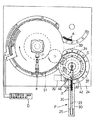
次に、前記第1方式から第3方式の製造方法に用いられる製造機について説明する。図6〜図11に示すように、ブロー成形又は真空成形された多数の容器本体Aを一直線状の供給経路に沿って載置搬送する搬送供給手段Fと、該搬送供給手段Fにて載置搬送されてきた容器本体Aを先頭のものから円弧状の送込み経路に沿って搬送する容器送込み手段Gと、この容器送込み手段Gから送込まれてきた容器本体Aの肩部又はその近くを挟持して、該容器本体Aの水平方向及び少なくとも下方への移動を阻止した状態で円弧状の挟持移送経路に沿って移送する挾持移送手段Hと、該挾持移送手段Hの円弧状挟持移送経路に沿って移送されてくる加工後の容器本体Aを受け取って円弧状の送出し経路に沿って移送する容器送出し手段Jとが設けられている。
【0040】
また、前記容器送込み手段Gには、容器本体Aの先端部である注液筒部6の一部を加熱する第1加熱手段Cが配設されているとともに、前記挾持移送手段Hには、該挾持移送手段Hで挾持移送される容器本体Aの先端部に対して、選択的に付替え自在に装着される凸状成形型20又は針状成形型21若しくは単一成形型22を待機位置と成形加工位置とに切替え作動させる切替手段Kと、前記挾持移送手段Hの一対の挾持爪で挾持移送される容器本体Aのうち、一対の挾持爪から突出する先端側の部位に対して容器軸線X方向から外嵌する状態と離脱させた待機状態とに切替えられる芯出し手段Lとが配設され、更に、前記挾持移送手段Hの円弧状挾持移送経路の途中には、成形型である針状成形型21又は単一成形型22を加熱する第2加熱手段の一例である高周波誘導加熱手段Dが設けられている。
【0041】
前記搬送供給手段Fは、図6に示すように、機枠24に取付られた搬送フレーム25の長手方向両端部に、電動モータ26に連動された横軸芯周りで回転自在な駆動スプロケット (図示せず)と、横軸芯周りで回転自在な従動スプロケット(図示せず)とを設け、前記両スプロケットに亘って、多数の容器本体Aを載置搬送する無端搬送体29を巻回するとともに、無端搬送体29上の容器本体Aを搬送案内する左右一対の搬送ガイド板30を設けて構成されている。
【0042】
前記容器送込み手段Gは、図6、図7に示すように、電動モータ33に連動して縦軸芯周りで駆動回転される駆動回転板34の外周縁部に、前記搬送供給手段Fから送出されてくる先頭の容器本体Aが入り込み保持される複数の凹状の保持部35を円周方向に沿って一定ピッチで形成するとともに、前記各保持部35内に保持された容器本体Aの底部を受け止めて移送案内する載置ガイド板36と、前記各保持部35内に保持された容器本体Aの回転半径方向外方への抜け出し移動を阻止する移送ガイド37とを設けて構成されている。
【0043】
前記第1加熱手段Cは、前述した第1方式及び第二方式の製造時にのみ使用されるものであって、次のように構成されている。
即ち、図6、図7に示すように、前記容器送込み手段Gの駆動回転板34のうち、各保持部35に対応する部位(当該図面では簡略化して一箇所だけ記載してある)の各々に、該駆動回転板34に貫通形成された一対の貫通孔34aに沿って上下方向に摺動する一対の昇降ガイド軸40a,40bを備えた昇降枠40を、圧縮コイルスプリング41にて下降側に移動付勢した状態で設けるとともに、前記各昇降枠40の上部には、保持部35に保持された容器本体Aの注液筒部6の根元側部分に対して容器軸線X方向から脱着自在に外嵌可能な遮熱板42を取付けてある。
【0044】
また、前記各昇降枠40の下部に設けたローラ43の回動移動軌跡に対応位置する機枠24側の支持部材44には、搬送供給手段Fの容器供給位置から挾持移送手段Hへの容器受渡位置に送込み搬送されるとき、前記遮熱板42を容器本体Aの注液筒部6の根元側部分に外嵌させた遮熱作用姿勢に下降させ、かつ、容器受渡位置から容器供給位置に戻し搬送されるとき、前記圧縮コイルスプリング41の弾性復元力に抗して遮熱板42を上方に離間した待機姿勢に上昇させるカム部材45を高さ調節自在に取付けてある。
【0045】
更に、前記容器送込み手段Gの駆動回転板34のうち、各保持部35に対応する部位の各々には、各保持部35に保持された容器本体Aの先端部である注液筒部6の頂部に対して、200℃〜500℃の熱風を供給する熱風供給管46を設けてある。
【0046】
前記挾持移送手段Hは、図6、図8、図10に示すように、電動モータ50に連動して縦軸芯周りで駆動回転される駆動回転板51の外周縁部で、かつ、その回転方向に所定間隔を隔てた複数箇所(当該図面では簡略化して一箇所だけ記載してある)の各々に、駆動回転板51の回転軸芯と平行な縦軸芯周りで回動自在な一対の作動軸42を支承し、両作動軸42の上端部には、容器本体Aの環状溝部となる首部3に対して水平方向から嵌合状態で挾持するための半円弧状の挾持面53aを備えた一対の挾持爪43を取付けるとともに、前記両作動軸42には、互いに噛合連動するギヤ54を外嵌固定し、更に、一方の作動軸42の下端部に固着した作動アーム55と駆動回転板51側との間に、前記一対の挾持爪43を開閉作動させる流体シリンダ56を架設してある。
【0047】
また、前記両挾持爪43に挾持移送される容器本体Aの底部1を載置状態で摺動案内する載置摺動ガイド板57と、前記両挾持爪43に挾持移送される容器本体Aの回転半径方向外方への抜け出し移動を阻止する移送ガイド部材58とを設けてある。
【0048】
そして、前記一対の挾持爪43で容器本体Aの首部3を挾持した状態では、該容器本体Aの水平方向及び少なくとも下方への移動を阻止した状態にあるから、容器本体Aと前記切替手段Kに付替え自在に装着される凸状成形型20又は針状成形型21若しくは単一成形型22との芯合わせ精度が高くなるとともに、成形型の押圧に伴う容器本体Aの容器軸線X方向での弾性変形に起因する有底円錐状の凹部6b及び小径の注液孔6cの加工精度の低下を抑制することができる。
【0049】
前記切替手段Kは、図8、図9に示すように、駆動回転板51のうち、各両挾持爪43に対応する複数箇所(当該図面では簡略化して一箇所だけ記載してある)の各々に、回転半径方向及び上下方向に往復移動される可動枠60を配置し、この可動枠60の先端側取付け部60Aの回転半径方向の二個所には、下方に向かって開口する軸装着口を備えた二本のホルダ筒軸62を、ナット63を介して脱着自在に取付けるとともに、前記各ホルダ筒軸62の軸装着口には、凸状成形型20の取付け軸20A又は針状成形型21の取付け軸21A若しくは単一成形型22の取付け軸22Aを選択的に付け替え自在に保持するナット61を螺合装着してある。
また、前記可動枠60の二本の水平スライド軸60Bを摺動自在に保持する昇降ブロック64には、駆動回転板51に対して昇降自在に摺動する二本の長さの異なる垂直スライド軸65,66を下方に延出し、そのうち、長尺の垂直スライド軸65の下端部を、機枠24に設けられた一対の昇降ガイド軸68に沿って摺動自在な昇降連結体67に連結するとともに、前記昇降連結体67の幅方向中央位置に上下方向から螺合されたネジ軸70を、機枠24に固定された電動モータ69に連動し、更に、前記昇降ブロック64に対して可動枠60を回転半径方向にスライド移動させる流体圧シリンダ71を、前記駆動回転板51に取付けてある。
【0050】
前記両ホルダ筒軸62のうち、回転半径方向内方に位置する短尺側の第1ホルダ筒軸62の軸芯は、一対の挾持爪43で挾持された容器本体Aの軸線Xと合致するように構成されていて、回転半径方向内方に位置する長尺側の第2ホルダ筒軸62に選択的に装着された凸状成形型20又は針状成形型21若しくは単一成形型22を成形作動させる場合には、前記流体圧シリンダ71を作動制御して、第2ホルダ筒軸62の軸芯が、一対の挾持爪43で挾持された容器本体Aの軸線Xと合致する位置までスライドさせる。
【0051】
また、前記両ホルダ筒軸62に選択的に装着された凸状成形型20又は針状成形型21若しくは単一成形型22を成形作動させる場合には、前記電動モータ69を駆動制御して可動枠60を所定量だけ下降させ、成形型を待機位置から成形加工位置に切替え作動させる。
【0052】
前記芯出し手段Lは、図8、図11に示すように、前記垂直スライド軸65,66に沿ってスライド移動自在に外装された可動筒状体75の上部に、一対の挾持爪43で挾持された容器本体Aのネジ筒部5に対して容器軸線X方向から外嵌する嵌合孔76aを形成してある芯出環状体76を取付けるとともに、前記可動筒状体75と機枠24側との間には、前記芯出環状体76を容器本体Aのネジ筒部5に嵌合する芯出し位置と上方に離間させた待機位置とに切替え作動させる流体圧シリンダ77を取付けてある。
【0053】
前記両ホルダ筒軸62の各々には、図11(イ)に示すように、冷却手段Eを構成するウォータージャケット80が形成されているとともに、前記ウォータージャケット80に冷却水を供給する給水接続管81と、ウォータージャケット80内の冷却水を排出する排水接続管82とが設けられている。
【0054】
そして、前述の如く、成形と同時に液体が密封状態で充填されている容器本体Aの肩部又はその近くを挾持して、該容器本体Aの水平方向及び少なくとも下方への移動を阻止した状態で経路に沿って移送する挾持移送手段Hと、該挾持移送手段Hで挾持移送される容器本体Aの先端部に対して、前記凹部6bを成形する凸状成形型20及び前記注液孔6cを形成する針状成形型21を待機位置と成形加工位置とに切替え作動させる切替手段Kとを設けた場合には、次の作用・効果を奏する。
【0055】
即ち、ブロー成形や真空成形等による成形と同時に液体が密封状態で充填されている熱可塑性材料製の容器本体A(ボトルパック型の容器本体)を利用して、この容器本体Aの先端部に、先端側ほど内径が大となる有底円錐状の凹部6bと、容器本体Aから押出される液滴量を設定量に制御するための小径の注液孔6cとを直接形成するが故に、射出成形された中栓部材を用いる開口点眼容器に比して容器本体を製造するための金型が少なくて済むととともに、有底円錐状の凹部6bと小径の注液孔6cとの存在により、容器本体Aの押圧操作に連れて常に一定量の液体を確実に滴下投与することができる。
【0056】
しかも、前記挾持移送手段Hで挾持移送される容器本体Aの先端部に対して、凸状成形型20及び針状成形型21を待機位置から成形加工位置に切替え作動させて有底円錐状の凹部6b及び小径の注液孔6cを形成する際、容器本体Aの肩部又はその近くを挾持移送手段Hで挾持して、該容器本体Aの水平方向及び少なくとも下方への移動を阻止してあるから、容器本体Aと凸状成形型20及び針状成形型21との芯合わせ精度が高くなるとともに、容器本体Aの容器軸線X方向での弾性変形に起因する有底円錐状の凹部6b及び小径の注液孔6cの加工精度の低下を抑制することができる。
【0057】
従って、容器本体Aの押圧操作に連れて常に一定量の液体を確実に滴下投与するための有底円錐状の凹部6b及び注液孔6cの加工精度の向上を図りながら、ボトルパック型の容器本体Aの持つ利点である製造コストの低廉化をより促進することができる。
【0058】
また、前述の如く、前記挾持移送手段Hの挾持爪53で挾持移送される容器本体Aのうち、挾持爪53から突出する先端側の部位に対して容器軸線X方向から外嵌する状態と離脱させた待機状態とに切替えられる芯出し手段Lが設けられている場合には、次の作用・効果を奏する。
【0059】
即ち、前記挾持移送手段Hの挾持爪53で挾持された容器本体Aの先端側の部位に対して、容器軸線X方向から芯出し手段Lを外嵌させることにより、容器本体Aと凸状成形型20及び針状成形型21との芯合わせ精度が更に高くなり、容器本体Aの押圧操作に連れて常に一定量の液体を確実に滴下投与するための有底円錐状の凹部6b及び注液孔6cの加工精度の向上を促進することができる。
【0060】
更に、前述の如く、前記挾持移送手段Hの挾持移送経路の途中に、成形型を加熱する高周波誘導加熱手段Dが設けられている場合には、前記挾持移送手段Hで容器本体Aを連続的に挟持移送しながら、その移送経路途中に設けた高周波誘導加熱手段Dによって、成形型を設定加熱温度にまで急速に過熱することができるから、製造能率及び加工精度の向上を促進しつつ歩留まりの改善をさらに図ることができる。
【図面の簡単な説明】
【図1】本発明の開口点眼容器を示す断面正面図
【図2】(イ)〜(ニ)は、容器本体のブロー成形又は真空成形による成形工程図
【図3】(イ)〜(ニ)は、第1方式による製造方法を示す工程説明図
【図4】(イ)〜(ニ)は、第2方式による製造方法を示す工程説明図
【図5】(イ)〜(ニ)は、第3方式による製造方法を示す工程説明図
【図6】開口点眼容器の製造機を示す概略平面図
【図7】容器送込み手段の拡大断面面図
【図8】挾持移送手段、切替手段、芯出手段の拡大断面図
【図9】切替手段の要部の拡大図
【図10】挾持爪の駆動系統図
【図11】(イ)〜(ハ)は、第1方式による製造工程を示す要部の拡大断面図
【符号の説明】
A 容器本体
B キャップ
D 第2加熱手段(高周波誘導加熱手段)
H 挾持移送手段
K 切替手段
L 芯出手段
X 容器軸芯
5a ネジ部(雄ネジ部)
6b 凹部
6c 注液孔
20 凸状成形型
21 針状成形型
22 単一成形型
53 挾持爪[0001]
BACKGROUND OF THE INVENTION
The present invention relates to an open eye drop container used for a medical eye drop and a method for producing the same.
[0002]
[Prior art]
In medical ophthalmic solutions, it is necessary to control the amount of eye drops to a constant amount.
As a general open eye drop container capable of controlling the amount of eye drops, an inner plug member of an injection-molded product is fitted and fixed to a cylindrical mouth portion of a molded container body. Forming a conical recess with a bottom having a large inner diameter, and a small-diameter injection hole for controlling the amount of liquid droplets that are pushed out from the container body through the inside and outside at the center of the bottom surface of the recess, and Screw the cap of the injection-molded product provided with a cap-like projection for sealing the bottomed conical recess of the inner plug member in a fitted state to the male thread formed on the outer peripheral surface of the cylindrical mouth portion of the container body. The fitted one is widely used.
[0003]
In the case of this open eye drop container, due to the presence of a bottomed conical recess formed in the inner plug member and a small-diameter liquid injection hole penetratingly formed at the center of the bottom surface of the recess, the pressing operation of the container body is accompanied. Although a certain amount of liquid can always be reliably dripped, a mold for injection molding of each of the three members is required, and each member must be cleaned and sterilized, resulting in a low manufacturing cost. Get higher.
[0004]
On the other hand, an integrally molded container is used as a container capable of reducing the manufacturing cost and maintaining the function as an open eye drop container. In this container, a male body formed on the outer peripheral surface on the front end side of a thermoplastic resin container body (commonly called a bottle pack-type container body) filled and sealed simultaneously with blow molding or vacuum molding. A cap, which is integrally formed with a needle-like protrusion for forming a liquid injection hole through the tip of the container body, is detachably screwed into the threaded portion, and tightened one step deeper than the normal closing position of the cap. The liquid injection hole is formed so as to penetrate through the tip of the container main body with the needle-like protrusion of the cap by screwing to the insertion side.
[0005]
[Problems to be solved by the invention]
The bottle pack type open eye drop container described above has an advantage that the manufacturing cost can be reduced as compared with the open eye drop container using the injection-molded inner plug member, but the tip of the container body is attached to the cap. Since the liquid injection hole is formed while piercing with the needle-like protrusion, the shape and size of the liquid injection hole will be uneven if the amount of screwing operation from the normally closed position of the cap to the tightening side is not performed properly. There is a possibility that the amount of droplets extruded from the container main body may vary.
[0006]
In addition, if the cap is excessively operated from the normal closing position to the tightening side after the liquid injection hole has been formed through the tip of the container body, the needle-like protrusions on the cap are required for each excessive tightening operation. The liquid injection hole will be expanded, and the amount of liquid droplets extruded from the container body may gradually increase.
[0007]
For this reason, it is necessary to fully explain how to use the open eye drop container. However, even if sufficient explanation is given, the cap is properly screwed to the tightening side to perforate, or the cap Since the tightening operation may be excessive, it has been difficult to reliably avoid the erroneous use as described above.
[0008]
The present invention has been made in view of the above-described situation, and the first main problem is that the container can be used without losing the superiority in terms of manufacturing cost, which is an advantage of the bottle pack-type container body. The second main problem is to provide a manufacturing method that can promote a reduction in manufacturing cost, which is to provide an open eye drop container that can always reliably drop a predetermined amount of liquid as the body is pressed. The point is to provide a method.
[0009]
[Means for Solving the Problems]
The characteristic configuration of the open eye drop container according to
According to the above characteristic configuration, a container body made of a thermoplastic material (bottle pack type container body) filled with a liquid in a sealed state simultaneously with molding by blow molding, vacuum molding or the like is used. A conical recess with a bottom that has a larger inner diameter on the tip side and a small-diameter injection hole for controlling the amount of liquid droplets extruded from the container body to a set amount are directly formed at the tip.it can. for that reason,Compared to an open eye drop container using an injection-molded inner stopper member, the number of molds for manufacturing the container body can be reduced, and the presence of a conical recess with a bottom and a small-diameter injection hole allows A constant amount of liquid can always be reliably administered dropwise as the body is pressed.
In addition, since the convex mold for molding the concave portion and the needle-shaped mold for forming the liquid injection hole are merely pressed from the container axial direction, the bottomed conical concave portion and It is also possible to form a small diameter injection hole.
Therefore, it is only necessary to form a bottomed conical recess and a small-diameter liquid injection hole at the front end portion of the bottle pack type container main body so that the inner plug function is exhibited. Thus, a certain amount of liquid can always be reliably dripped and administered without impairing the superiority in manufacturing cost.
Moreover, the burr | flash at the time of the blow molding which protrudes on the outer peripheral surface of the liquid injection cylinder part of a container main body can be removed with the bowl-shaped molding surface of a convex-shaped shaping | molding die. A particularly important point of the open eye drop container according to the present invention is that the liquid is sealed at the same time as forming the recess having a shape capable of penetrating a small-diameter liquid injection hole for controlling the droplet amount to a set amount. It is to form at the front-end | tip part of the container main body made from the thermoplastic material with which it filled with. From this, within the framework of the present invention,like thatAn open eye dropper as a semi-finished product with a recess is also included.The
The configuration of such an open eye drop container is, as described in
[0010]
A characteristic configuration of the open eye drop container according to
According to the above characteristic configuration, since the screw part for screwing the cap onto can be formed simultaneously with the molding of the container main body, the manufacturing cost can be reduced.
[0011]
A characteristic configuration of the open eye drop container according to
According to the above characteristic configuration, the depth of the concave portion is desirably as deep as possible. However, from the technical aspect of obtaining a yield and a stable inner plug function, the depth is desirably in the range of 5 to 7 mm, most preferably. It is about 6 mm. When the depth of the concave portion becomes smaller than an appropriate value, the tip of the concave portion, that is, the injection hole is covered with the liquid accumulated by the surface tension in the annular space (liquid reservoir) formed around the concave portion, There arises a problem that the liquid in the liquid pool jumps out through the liquid injection hole due to the pressure generated when the container is held by hand. Further, if the depth of the concave portion is larger than an appropriate value, a defect such as a crack in the concave portion is likely to occur during the step of forming the concave portion. The optimum solution that satisfies such conflicting conditions is 6 mm. However, in the case of a chemical solution having a low surface tension, the amount of liquid pool is small and the depth of the recess is not so great, so that the depth of the recess can be designed to be shallow.
[0012]
The characteristic configuration of the open eye drop container according to
According to the above characteristic configuration, the liquid is filled in the container main body (surface tension, viscosity), and is adjusted within a range of φ2.0 mm to φ4.0 mm.
In order to make the amount of one drop constant (adjusted within the range of 25 to 50 microliters per drop according to the purpose), in the case of a liquid with a large surface tension, the mouth diameter is reduced and the surface tension is small. In the case of liquid, the diameter of the mouth is increased.
[0013]
The characteristic configuration of the manufacturing method of the open eye drop container according to
According to the above characteristic configuration, a container body made of a thermoplastic material (bottle pack type container body) filled with a liquid in a sealed state simultaneously with molding by blow molding, vacuum molding or the like is used. Because the bottomed conical concave portion whose inner diameter is larger toward the distal end side and the small-diameter injection hole for controlling the amount of droplets extruded from the container body to a set amount are directly formed at the distal end portion. Compared to an open eye drop container using an injection-molded inner stopper member, the number of molds for manufacturing the container body can be reduced, and the presence of a conical recess with a bottom and a small-diameter injection hole allows A constant amount of liquid can always be reliably administered dropwise as the body is pressed.
In addition, since the convex mold for molding the concave portion and the needle-shaped mold for forming the liquid injection hole are merely pressed from the container axial direction, the bottomed conical concave portion and It is also possible to form a small diameter injection hole.
Therefore, it is only necessary to form a bottomed conical recess and a small-diameter liquid injection hole at the front end of the bottle pack type container main body so that the inner plug function can be exhibited. Therefore, it is possible to advantageously manufacture an open eye dropper container that can always reliably drop and dispense a fixed amount of liquid in terms of manufacturing cost.
Moreover, the burr | flash at the time of the blow molding which protrudes on the outer peripheral surface of the liquid injection cylinder part of a container main body can be removed with the bowl-shaped molding surface of a convex-shaped shaping | molding die.
Moreover, the manufacturing method for the open eye drop container as the semi-finished product in which the concave portion according to the present invention is formed as described above, as shown in claim 7,At the same time as blow molding or vacuum molding, a convex mold that molds the concave portion is pressed from the container axial direction to the tip of the container body that is filled with liquid in a sealed state. Further, during molding by the convex mold The outer peripheral surface of the liquid injection cylinder part of the container body is molded by the bowl-shaped molding surface.It has the above-mentioned effects.
[0014]
A characteristic configuration of the method for manufacturing an open eye drop container according to claim 8 of the present invention is that at least a portion molded by the convex mold is heated to a temperature at which it is not buckled by a heating means before molding.
According to the above characteristic configuration, it is possible to improve the processing accuracy of the concave portion formed at the distal end portion of the container body and improve the yield.
[0015]
According to a ninth aspect of the present invention, there is provided a characteristic configuration of the method for manufacturing an open eye drop container, wherein the convex mold and the needle mold are integrally formed, and the concave portion is formed at the tip of the container. And injecting holes.
According to the above characteristic configuration, the bottomed conical recess and the small-diameter liquid injection hole can be formed with a single mold, so that the production efficiency can be improved and the production equipment can be simplified.
[0016]
DETAILED DESCRIPTION OF THE INVENTION
[First Embodiment]
FIG. 1 shows an open eye drop container of the present invention mainly used for medical purposes, and a container body A made of a flexible thermoplastic material filled with a predetermined amount of a chemical solution simultaneously with blow molding or vacuum molding, It is comprised from the cap B detachably screwed to the
[0017]
The container body A includes a
[0018]
The liquid
[0019]
The depth of the
In order to make the amount of one drop constant (adjusted within the range of 25 to 50 microliters per drop according to the purpose), in the case of liquidity with a large surface tension, the diameter of the
[0020]
Further, the
[0021]
Examples of the thermoplastic material that is a constituent material of the container body A include polyethylene, polyethylene-polypropylene, polypropylene, polyethylene terephthalate, polycarbonate, and the like. The cap B is screwed into the
[0022]
Since the manufacturing method of the container main body A before the said recessed
As shown in FIG. 2 (a), a pair of main molding dies 11 having a
[0023]
Next, as shown in FIG. 2 (b), the main molding die 11 is closed and operated, and the
When this liquid filling step is completed, as shown in FIG. 2 (2), the
[0024]
Next, a three-method manufacturing method of forming a bottomed
In the manufacturing method of the first method shown in FIGS. 3 (a) to 3 (d), a metal
The
[0025]
In the manufacturing method of the first method, as shown in FIG. 3A, a part of the liquid
In the case where the thermoplastic material of the container body A is a soft resin material such as polyethylene, the tip portion will buckle unless heated, so that at least the portion molded by the
[0026]
Next, as shown in FIG. 3B, the
At this time, the burr at the time of blow molding protruding from the outer peripheral surface of the liquid
[0027]
The
The
[0028]
Next, as shown in FIGS. 3C and 3D, the needle-shaped
In the step of forming the
[0029]
The needle-shaped
When the needle-shaped
[0030]
The needle-shaped
[0031]
[Second Method Manufacturing Method]
In the manufacturing method of the second system shown in FIGS. 4 (a) to 4 (d), similarly to the first system, the metal
The convex molding die 20 is configured by forming only a
[0032]
In the first method, as shown in FIG. 3B, the burr at the time of blow molding protruding from the outer peripheral surface of the liquid
[0033]
[Manufacturing Method of Third Method]
In the third method of manufacturing shown in FIGS. 5 (a) to 5 (d), a convex mold for forming the bottomed
[0034]
In the third method, as shown in FIGS. 5 (a) and 5 (b), the tip side of the
[0035]
The needle-shaped forming
As shown in FIG. 5 (d), the
[0036]
Although it is preferable that the conical forming
[0037]
The mounting
And when the said single shaping | molding die 22 is cooled to predetermined temperature, this single shaping | molding die 22 is extracted along the container axis X direction from the liquid
[0038]
The
The bottomed
In the second method and the third method described above, the needle-
[0039]
Next, a manufacturing machine used in the first to third manufacturing methods will be described. As shown in FIGS. 6 to 11, a transport supply means F for mounting and transporting a large number of blown or vacuum molded container bodies A along a straight supply path, and the transport supply means F for mounting. Container feeding means G for conveying the container main body A that has been conveyed along the arc-shaped feeding path from the top, and the shoulder of the container main body A that has been fed from the container feeding means G or its A sandwiching transfer means H for transporting along the arcuate sandwiching and transporting path in a state where the vicinity of the container main body A is sandwiched and prevented from moving in the horizontal direction and at least downward, and the arcuate sandwiching of the sandwiching transporting means H Container sending means J is provided for receiving the processed container main body A transferred along the transfer path and transferring it along the arc-shaped sending path.
[0040]
Further, the container feeding means G is provided with a first heating means C for heating a part of the liquid
[0041]
As shown in FIG. 6, the conveyance supply means F is a drive sprocket that is rotatable around a horizontal axis linked to an
[0042]
As shown in FIGS. 6 and 7, the container feeding means G is connected to the outer peripheral edge portion of the
[0043]
The first heating means C is used only during the manufacturing of the first method and the second method described above, and is configured as follows.
That is, as shown in FIGS. 6 and 7, portions of the
[0044]
Further, the
[0045]
Further, in each of the portions corresponding to the holding
[0046]
As shown in FIGS. 6, 8, and 10, the gripping transfer means H is an outer peripheral edge portion of a driving
[0047]
Further, the mounting
[0048]
When the
[0049]
As shown in FIGS. 8 and 9, the switching means K is provided at each of a plurality of locations (in the drawing, only one location is simplified) corresponding to the both holding
Further, the elevating
[0050]
Of the two
[0051]
Further, when the
[0052]
As shown in FIGS. 8 and 11, the centering means L is clamped by a pair of
[0053]
Each of the holder
[0054]
As described above, the container body A, which is filled with the liquid in a sealed state at the same time as the molding, is gripped at or near the shoulder, and the container body A is prevented from moving in the horizontal direction and at least downward. A
[0055]
That is, a container body A (bottle pack type container body) made of a thermoplastic material filled with a liquid in a sealed state at the same time as molding by blow molding or vacuum molding is used. The bottomed
[0056]
In addition, the
[0057]
Accordingly, a bottle pack type container is provided while improving the processing accuracy of the bottomed
[0058]
Further, as described above, in the container main body A which is held and transferred by the holding
[0059]
That is, the container body A and the convex shape are formed by externally fitting the centering means L from the container axis X direction to the distal end side portion of the container body A held by the holding
[0060]
Further, as described above, when the high frequency induction heating means D for heating the mold is provided in the middle of the holding transfer path of the holding transfer means H, the container main body A is continuously moved by the holding transfer means H. The high frequency induction heating means D provided in the middle of the transfer path can be used to rapidly heat the mold to the set heating temperature while promoting the improvement in manufacturing efficiency and processing accuracy. Further improvements can be made.
[Brief description of the drawings]
FIG. 1 is a cross-sectional front view showing an open eye drop container of the present invention.
FIGS. 2A to 2D are molding process diagrams of a container body by blow molding or vacuum molding.
FIGS. 3A to 3D are process explanatory views showing a manufacturing method according to the first method. FIGS.
FIGS. 4A to 4D are process explanatory views showing a manufacturing method according to the second method.
FIGS. 5A to 5D are process explanatory views showing a manufacturing method according to a third method.
FIG. 6 is a schematic plan view showing an open eye dropper manufacturing machine.
FIG. 7 is an enlarged sectional view of the container feeding means.
FIG. 8 is an enlarged cross-sectional view of the gripping transfer means, switching means, and centering means.
FIG. 9 is an enlarged view of the main part of the switching means.
[Fig. 10] Driving system diagram of the holding claw
FIGS. 11A to 11C are enlarged cross-sectional views of main parts showing a manufacturing process according to the first method. FIGS.
[Explanation of symbols]
A Container body
B Cap
D Second heating means (high frequency induction heating means)
H Holding and transporting means
K switching means
L Centering means
X Container axis
5a Screw part (male screw part)
6b recess
6c Injection hole
20 Convex mold
21 Needle-shaped mold
22 Single mold
53 Nail Claw
Claims (9)
この凹部の底面に、針状成形型を容器軸線方向から圧接して貫通形成することにより、前記容器本体から押出される液滴量を設定量に制御可能な小径の注液孔を備え、
さらに、前記凸状成形型による成形時、および、前記針状成形型による成形時の少なくとも何れか一方のときに、前記容器本体の注液筒部に、椀状の成形面を有する成形型により、前記凹部の外側に成形した外周面を備えた開口点眼容器。The inner diameter is larger toward the tip of the container body made of a thermoplastic material, which is filled with liquid in a sealed state simultaneously with blow molding or vacuum molding, as the tip is formed by pressing the convex mold from the container axial direction. With a bottomed conical recess
On the bottom surface of the recess, a needle-shaped mold is pressed from the container axial direction to form a penetrating hole, thereby providing a small-diameter liquid injection hole capable of controlling the amount of droplets extruded from the container body to a set amount,
Further, at least one of molding with the convex mold and molding with the needle-shaped mold , the mold having a bowl-shaped molding surface on the liquid injection cylinder portion of the container body An open eye drop container having an outer peripheral surface formed on the outside of the recess .
この凹部は、この凹部の底面に前記容器本体から押出される液滴量を設定量に制御可能な小径の注液孔を貫通形成可能となる形状を備え、
さらに、前記凸状成形型による成形時に、前記容器本体の注液筒部に、椀状の成形面を有する成形型により、前記凹部の外側に成形した外周面を備えた開口点眼容器。The inner diameter is larger toward the tip of the container body made of a thermoplastic material, which is filled with liquid in a sealed state simultaneously with blow molding or vacuum molding, as the tip is formed by pressing the convex mold from the container axial direction. With a bottomed conical recess
The recess is provided with a through-formable become shape controllable small diameter instilling hole set amount drop volume to be extruded from the container body to the bottom surface of the recess,
Furthermore, the open eye drop container provided with the outer peripheral surface shape | molded on the outer side of the said recessed part by the shaping | molding die which has a bowl-shaped shaping | molding surface in the liquid injection cylinder part of the said container main body at the time of shaping | molding by the said convex shape shaping | molding die .
さらに、前記凸状成形型による成形時、および、前記針状成形型による成形時の少なくとも何れかのときに、椀状の成形面により前記容器本体の注液筒部の外周面を成形する開口点眼容器の製造方法。6. A method of manufacturing an open eye drop container according to claim 1, 3, 4 or 5, wherein the concave portion is formed at the tip of the container body filled with a liquid in a sealed state simultaneously with blow molding or vacuum molding. Pressure-contacting the mold-shaped mold and the needle-shaped mold that forms the liquid injection hole from the container axial direction,
Furthermore, an opening for forming the outer peripheral surface of the liquid injection cylinder portion of the container body by a bowl-shaped molding surface at least one of molding by the convex mold and molding by the needle-shaped mold Manufacturing method of eye drop container.
Priority Applications (1)
| Application Number | Priority Date | Filing Date | Title |
|---|---|---|---|
| JP2000243923A JP3694446B2 (en) | 1999-08-17 | 2000-08-11 | Open eye drop container and manufacturing method thereof |
Applications Claiming Priority (3)
| Application Number | Priority Date | Filing Date | Title |
|---|---|---|---|
| JP11-230651 | 1999-08-17 | ||
| JP23065199 | 1999-08-17 | ||
| JP2000243923A JP3694446B2 (en) | 1999-08-17 | 2000-08-11 | Open eye drop container and manufacturing method thereof |
Related Child Applications (1)
| Application Number | Title | Priority Date | Filing Date |
|---|---|---|---|
| JP2005012134A Division JP4681306B2 (en) | 1999-08-17 | 2005-01-19 | Manufacturing method of eye drop container |
Publications (2)
| Publication Number | Publication Date |
|---|---|
| JP2001120639A JP2001120639A (en) | 2001-05-08 |
| JP3694446B2 true JP3694446B2 (en) | 2005-09-14 |
Family
ID=26529459
Family Applications (1)
| Application Number | Title | Priority Date | Filing Date |
|---|---|---|---|
| JP2000243923A Expired - Lifetime JP3694446B2 (en) | 1999-08-17 | 2000-08-11 | Open eye drop container and manufacturing method thereof |
Country Status (1)
| Country | Link |
|---|---|
| JP (1) | JP3694446B2 (en) |
Families Citing this family (7)
| Publication number | Priority date | Publication date | Assignee | Title |
|---|---|---|---|---|
| ATE482685T1 (en) | 1999-08-17 | 2010-10-15 | Santen Pharmaceutical Co Ltd | OPEN INSTILLATION CONTAINER AND METHOD OF PRODUCING THE CONTAINER |
| JP3922910B2 (en) | 2001-10-31 | 2007-05-30 | 参天製薬株式会社 | Eye drops container with stepped part |
| CA2477418A1 (en) | 2002-03-18 | 2003-09-25 | Santen Pharmaceutical Co., Ltd. | High-temperature-sterilizable instillator |
| JP4549148B2 (en) * | 2003-10-07 | 2010-09-22 | 参天製薬株式会社 | Container manufacturing equipment |
| TW200513254A (en) * | 2003-10-07 | 2005-04-16 | Santen Pharmaceutical Co Ltd | Container manufacturing device |
| EP2416938B1 (en) * | 2009-04-07 | 2014-08-27 | Graham Packaging Company, L.P. | Method and apparatus for reforming a portion of a plastic container using induction heating |
| BE1022939B1 (en) * | 2015-08-19 | 2016-10-20 | Hubert De Backer Nv | Drop dispenser and method for manufacturing a drop dispenser |
-
2000
- 2000-08-11 JP JP2000243923A patent/JP3694446B2/en not_active Expired - Lifetime
Also Published As
| Publication number | Publication date |
|---|---|
| JP2001120639A (en) | 2001-05-08 |
Similar Documents
| Publication | Publication Date | Title |
|---|---|---|
| KR100544221B1 (en) | Method of manufacturing open instillation container | |
| JP3922910B2 (en) | Eye drops container with stepped part | |
| JP3694446B2 (en) | Open eye drop container and manufacturing method thereof | |
| EP3175969B1 (en) | Blow molding device | |
| US10189202B2 (en) | Blow molding device | |
| EP3894173B1 (en) | Method for forming a concave object | |
| JP4681306B2 (en) | Manufacturing method of eye drop container | |
| JP2005185846A5 (en) | ||
| BRPI0512486B1 (en) | method for manufacturing plastic containers and extruder | |
| CN103009607B (en) | Apparatus and method for molding plastic liner with double head openings | |
| JP4402591B2 (en) | Chemical container and method for manufacturing the same | |
| US6217817B1 (en) | Method for blow-molding tube container | |
| KR20150128315A (en) | Compressing Spray Can Manufacturing Unit Using Variable Heating Means and Method and Spray Can Manufactured Thereof | |
| JP2006151514A (en) | Liquid storage container, and manufacturing method for liquid storage container |
Legal Events
| Date | Code | Title | Description |
|---|---|---|---|
| A977 | Report on retrieval |
Free format text: JAPANESE INTERMEDIATE CODE: A971007 Effective date: 20040525 |
|
| A131 | Notification of reasons for refusal |
Free format text: JAPANESE INTERMEDIATE CODE: A131 Effective date: 20040701 |
|
| A521 | Written amendment |
Free format text: JAPANESE INTERMEDIATE CODE: A523 Effective date: 20040830 |
|
| A02 | Decision of refusal |
Free format text: JAPANESE INTERMEDIATE CODE: A02 Effective date: 20041118 |
|
| A521 | Written amendment |
Free format text: JAPANESE INTERMEDIATE CODE: A523 Effective date: 20050119 |
|
| A911 | Transfer of reconsideration by examiner before appeal (zenchi) |
Free format text: JAPANESE INTERMEDIATE CODE: A911 Effective date: 20050128 |
|
| A131 | Notification of reasons for refusal |
Free format text: JAPANESE INTERMEDIATE CODE: A131 Effective date: 20050407 |
|
| A521 | Written amendment |
Free format text: JAPANESE INTERMEDIATE CODE: A523 Effective date: 20050422 |
|
| TRDD | Decision of grant or rejection written | ||
| A01 | Written decision to grant a patent or to grant a registration (utility model) |
Free format text: JAPANESE INTERMEDIATE CODE: A01 Effective date: 20050616 |
|
| A61 | First payment of annual fees (during grant procedure) |
Free format text: JAPANESE INTERMEDIATE CODE: A61 Effective date: 20050624 |
|
| R150 | Certificate of patent or registration of utility model |
Free format text: JAPANESE INTERMEDIATE CODE: R150 |
|
| FPAY | Renewal fee payment (event date is renewal date of database) |
Free format text: PAYMENT UNTIL: 20080701 Year of fee payment: 3 |
|
| FPAY | Renewal fee payment (event date is renewal date of database) |
Free format text: PAYMENT UNTIL: 20080701 Year of fee payment: 3 |
|
| FPAY | Renewal fee payment (event date is renewal date of database) |
Free format text: PAYMENT UNTIL: 20110701 Year of fee payment: 6 |
|
| RVTR | Cancellation of determination of trial for invalidation | ||
| FPAY | Renewal fee payment (event date is renewal date of database) |
Free format text: PAYMENT UNTIL: 20110701 Year of fee payment: 6 |
|
| FPAY | Renewal fee payment (event date is renewal date of database) |
Free format text: PAYMENT UNTIL: 20110701 Year of fee payment: 6 |