JP3689283B2 - Heat storage device - Google Patents
Heat storage device Download PDFInfo
- Publication number
- JP3689283B2 JP3689283B2 JP28229799A JP28229799A JP3689283B2 JP 3689283 B2 JP3689283 B2 JP 3689283B2 JP 28229799 A JP28229799 A JP 28229799A JP 28229799 A JP28229799 A JP 28229799A JP 3689283 B2 JP3689283 B2 JP 3689283B2
- Authority
- JP
- Japan
- Prior art keywords
- heat
- heat storage
- pump
- fluid
- fluid circuit
- Prior art date
- Legal status (The legal status is an assumption and is not a legal conclusion. Google has not performed a legal analysis and makes no representation as to the accuracy of the status listed.)
- Expired - Fee Related
Links
Images


Classifications
-
- Y—GENERAL TAGGING OF NEW TECHNOLOGICAL DEVELOPMENTS; GENERAL TAGGING OF CROSS-SECTIONAL TECHNOLOGIES SPANNING OVER SEVERAL SECTIONS OF THE IPC; TECHNICAL SUBJECTS COVERED BY FORMER USPC CROSS-REFERENCE ART COLLECTIONS [XRACs] AND DIGESTS
- Y02—TECHNOLOGIES OR APPLICATIONS FOR MITIGATION OR ADAPTATION AGAINST CLIMATE CHANGE
- Y02E—REDUCTION OF GREENHOUSE GAS [GHG] EMISSIONS, RELATED TO ENERGY GENERATION, TRANSMISSION OR DISTRIBUTION
- Y02E60/00—Enabling technologies; Technologies with a potential or indirect contribution to GHG emissions mitigation
- Y02E60/14—Thermal energy storage
Landscapes
- Other Air-Conditioning Systems (AREA)
- Air Conditioning Control Device (AREA)
Description
【0001】
【発明の属する技術分野】
本発明は、余剰の電力を熱に代えて蓄熱しておき、日中使用電力が大きくなった時に蓄熱しておいた熱を取り出して利用し、全体として電気エネルギーの消費量をできるだけ少なくすることができる蓄熱装置に関するものである。
【0002】
【従来の技術】
従来から、余剰電力を熱に代えて蓄熱しておくことにより、電力エネルギーを有効活用するシステムは実公平3−30744号公報等に有るように公知であり、またこれとは別に図11、図12に示すようなシステムも公知である。
ここで、図11に示すシステム構成を説明すると、
図11において、Rは冷熱温熱兼用冷凍機、P1は第1ポンプ、101は第1切替え弁、102は第2切替え弁であり、これらは蓄熱槽103と接続されている第1流体管路100内に直列に配置されている。また、この第1流体管路100とは別に蓄熱槽103と接続されている第2管路管路110が第1流体管路に対して並列に配置され、第2流体管路110内に蓄熱槽103に対して並列に複数の放熱器111と、放熱器111に対して直列に第2ポンプP2、第3切替え弁113、第4切替え弁114が接続されており、さらに各放熱器111毎に制御弁112が配置されている。
蓄熱槽103は冷却または加熱される流体が満たされており、各流体管路に配置された各切替え弁101、102、113、114は図示のように蓄熱槽に接続されている。
このシステムでは、例えば電力に余剰が生じる時間帯(夜間等の電力料金の安価な時間帯)を利用して第1ポンプP1および冷熱温熱兼用冷凍機Rを運転し、蓄熱槽103内の流体を冷却あるいは加熱して蓄熱槽103内に蓄熱をしておく。そして冷房あるいは暖房等の負荷が最大になる昼間等の時間帯に、蓄熱槽103内の流体を第2ポンプP2によって汲み上げ放熱器111に流して、冷房あるいは暖房を行うことができるようになっている。
しかしながら、このシステムでは、第1、第2ポンプおよび流体管路は、複数有る放熱器の最大負荷運転状態に対応して設備しておく必要があり、大型のポンプおよび断面積の大きな4本の流体管(主管)を使用する必要があり、設備費が高価になるなどの問題がある。
【0003】
また図12に示すシステムは、放熱器201および冷熱温熱兼用冷凍機Rを有する回路を密閉型流体回路とし、この密閉型流体回路内に熱交換器203を配置し、さらに此の密閉型流体回路とは別に前記熱交換器203と接続する大気開放型流体回路205を設け、熱交換器203を介して蓄熱槽204内に蓄熱したり、蓄熱槽204内の熱を熱交換器201に流したりすることができる構成を採用している。このシステムでは冷熱温熱兼用冷凍機から複数の放熱器に流体を供給する管を共通にするとともに第1ポンプP1への流入管路と放熱器201からの吐出管路とを別々の管で構成し、これによってコストの低減を図ろうとしたものである。しかしながら、このシステムにおいても、冷熱温熱兼用冷凍機から複数の放熱器に流体を供給する管路は最大負荷に併せた大きな断面積のものを使用する必要があり、システムのコスト低減には十分寄与していない。
【0004】
そこで、本発明は、蓄熱時と放熱時いずれの状態においても2本の管路で対応できるようにするとともに、その管路の太さを従来のそれと比較して細くできる蓄熱装置を提供し、上記問題を解決するとともに、ポンプが消費する搬送動力の低減を図ることを目的とする。
本発明は、密閉型流体回路と大気開放型流体回路とを熱交換器で接続し、この熱交換器を介して、夜間等の余剰の電力を熱に代えて蓄熱槽内に蓄熱しておき、日中使用電力が大きくなった時に蓄熱槽内に蓄熱しておいた熱を熱交換器を介して取り出して利用し、日中の消費電力を夜間にシフトするとともに流体搬送用電気エネルギーの消費量をできるだけ少なくすることができる蓄熱装置として構成されており、蓄熱槽内に蓄熱する蓄熱量は日中の最大負荷の全量でない蓄熱量(多くの計画は、50%近くの蓄熱量)とし、放熱時には各放熱器に供給する熱は蓄熱槽と熱源機とが分担するように構成されている。 このため、日中の負荷量が蓄熱量より大きい日の運転状況では、蓄熱時と放熱時に共用される配管内において両端より互いに冷(温)水を対向流として流し、それぞれに近い(流れの上流の)位置の各放熱器に対し必要とされる量が各分岐管を通じ供給されて行き、最後の放熱器には両者がそれぞれ受け持つ量が双方向より供給されることになる。そして各放熱器において必要とされた冷(温)水は、各放熱器において熱交換された後、蓄熱時と放熱時に共用される配管において相反する方向流を形成し、冷凍機、熱交換器に戻り循環を繰り返す。
また、日中の負荷量が蓄熱量以下の日の運転状況ではすべての負荷量を蓄熱槽に貯えた熱をもって対応することになる。この時の循環冷(温)水の全量は熱交換器を介し、蓄熱槽から熱を受けることになる。
【0005】
【課題を解決するための手段】
このため、本発明が採用した技術解決手段は、
流体を循環させることができる密閉型流体回路内に、熱源機とこの熱源機に流体を供給する第1ポンプと熱交換器とをこの順で直列に配置し、さらに前記熱源機と第1ポンプおよび熱交換器に対して並列に複数の管路を設け、これら夫々の管路に放熱器を配置し、さらに前記熱交換器に対して前記とは別の並列管路を設けこの管路内に第2ポンプを配置し、また前記熱交換器には密閉型流体回路とは別に蓄熱槽からの流体を循環させることができる蓄熱流体回路を接続してなり、前記密閉型流体回路内の熱源機と第一ポンプとを運転して前記熱源機により密閉型流体回路内の流体を冷却または加熱し、この冷却または加熱した流体を前記熱交換器に流して前記蓄熱流体回路内の流体を冷熱または加熱して蓄熱槽内に蓄熱する第一過程と、前記密閉型流体回路内の熱源機と第一ポンプとを必要に応じて運転して前記熱源機によって密閉型流体回路内の流体を冷却または加熱し、冷却または加熱された流体を前記放熱器の一部に循環させるとともに、前記第二ポンプを運転して前記密閉型流体回路内の流体を前記熱交換器に供給して前記蓄熱流体回路の流体によって冷却または加熱し、この流体を前記残りの放熱器に前記第1ポンプからの流れと対向する方向に流して冷房または暖房する第二過程とを選択できるようにしたことを特徴とする蓄熱装置であり、
複数階からなるビルの上階に熱源機とこの熱源機に直列に接続され前記熱源機に流体を供給する第1ポンプとを配置し、地上側の階に熱交換器を配置し、これらを密閉型流体回路で直列に接続し、さらに、この密閉型流体回路内の前記熱源機、第1ポンプと熱交換器の間の各階毎に前記熱源機と第1ポンプに対して並列の管路を形成して各管路内に放熱器を配置し、また、前記熱交換器に対して地上側に並列に管路を形成し、該管路内に第2ポンプを配置し、また前記熱交換器には密閉型流体回路とは別に蓄熱槽からの流体を循環させることができる大気開放型の蓄熱流体回路を接続して流体回路を構成し、前記密閉型流体回路内の熱源機と第一ポンプとを運転して前記熱源機により密閉型流体回路内の流体を冷却または加熱し、この冷却または加熱した流体を前記熱交換器に流して前記蓄熱回路内の流体を冷熱または加熱して蓄熱槽内に蓄熱する第一過程と、前記密閉型流体回路内の熱源機と第一ポンプとを必要に応じて運転して前記熱源機によって密閉型流体回路内の流体を冷却または加熱し、冷却または加熱された流体を前記上階から下階の放熱器に向けて循環させるとともに、前記第二ポンプを運転して前記密閉型流体回路内の流体を前記熱交換器に供給して前記蓄熱流体回路の流体によって冷却または加熱し、この流体を下階から上階の放熱器に向けて前記第1ポンプからの流れに対向する方向に流して冷房または暖房する第二過程とを選択できるようにしたことを特徴とする蓄熱装置である。
【0006】
【実施の形態】
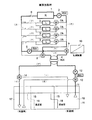
以下、図面に基づいて本発明の実施の形態を説明すると、図1は建築物内(たとえば高層ビル等)に本蓄熱装置を装備した第1実施形態に関わる蓄熱装置の構成図である。
【0007】
図において、1は夜間の蓄熱と日中の不足熱量を補うための熱源機としての冷熱温熱兼用冷凍機であり、切り替えによって冷熱と温熱とを供給出来る機能を有している。2は前記冷熱温熱兼用冷凍機1に流体を供給する第1ポンプであり、これら冷熱温熱兼用冷凍機1と第1ポンプ2とは流体回路内の最上部(例えばビルの最上階)に配置されている。3は建物内の各階を冷房又は暖房するための放熱器3であり、この放熱器3は各階毎に配置されている。4は流体回路内の最下部(例えばビルの地下等)に配置され安価な電力を熱に代え蓄熱槽(後述する)11内に蓄熱するための熱交換器、5は前記熱交換器の近くに配置され前記放熱器3に流体を流すための第2ポンプ、6は冷熱温熱兼用冷凍機1の吐出側に接続された一方向流れを形成する逆止弁、7は放熱器3の流入側管路に接続された制御弁、8は管路を切り替える第1切替え弁、9は管路を切り替える第2切替え弁、10は制御装置である。
【0008】
前記冷熱温熱兼用冷凍機1、第1ポンプ2、熱交換器4は図中の符号(カ)、(キ)で示す管路で直列に接続されており、また前記放熱器3は、冷熱温熱兼用冷凍機1、第1ポンプ2と前記熱交換器4との間で、冷熱温熱兼用冷凍機1と第1ポンプ2および熱交換器4のそれぞれに対して並列に複数配置された管路(ク)内に設けられており、また前記第2ポンプ5も前記熱交換器4に対して並列の管路(コ)内に配置されている。さらに第1切替え弁8は管路(カ)内に、また、第2切替え弁9は管路(キ)内に配置され、さらに第1切替え弁8は、第1ポンプ2と第2切替え弁9との間の管路(キ)に管路(ケ)により接続されている。そして、前記冷熱温熱兼用冷凍機1、第1ポンプ2、熱交換器4、放熱器3等が接続される管路は全体として図のように密閉型流体回路を構成している。
また、第1ポンプ2および第2ポンプ5は運転状態によって吐出流量を変えることができる機能を有しており、さらに前記第1、第2切替え弁8、9、制御弁7も共に、制御装置10からの指令によって管路の切替えや流量が制御される構成となっている。
【0009】
前記熱交換器4には大気開放型流体回路(ア)が接続され、この流体回路は蓄熱槽11に接続され、大気開放型流体回路は循環ポンプ12と二つの分岐切替え弁13、14を備えている。
蓄熱槽11は複数の隔壁15によって区画された槽を有し、各槽は連通管16で連通され、さらにそのうち図中左側の槽17は低温側として右側の槽18は高温側として機能を果たし、各槽は水等の流体によって満たされている。そして、蓄熱槽11の低温側の槽17および高温側の槽18には前記二つの分岐切替え弁13、14に接続する管路(ウ)、(オ)、(イ)、(エ)が図のように配置されており、この大気開放型流体回路と蓄熱槽11とによって、余剰電力を熱に代えて蓄熱する蓄熱手段を構成している。なおこの蓄熱手段は従来から公知のものであり、また種々の蓄熱手段を使用することができ、本発明の特徴部ではないので詳細な説明は省略する。
【0010】
つづいて、上記蓄熱装置の運転状態を説明する。
冷房蓄熱時(図2)
図2は安価な電力を使用して蓄熱槽11内に冷熱蓄熱する状態のシステム図であり、図中太線が運転されている状態の管路である。
基本動作
密閉型流体回路は、熱源である冷熱温熱兼用冷凍機1、第1ポンプ2は運転状態にあり、第1切替え弁8、第2切替え弁9は、密閉型流体回路(カ)、(キ)を連通するように切替えられ、さらに各放熱器3用の制御弁7は強制的に遮断され、第2ポンプ5は停止状態とする。また、大気開放型回路(ア)側は、循環ポンプ12は運転され、分岐切替え弁13、14は図のように直流を形成するように切換られる。
この状態において、大気開放型回路側では、蓄熱槽11の高温槽18側の上部より、配管(ウ)を介し循環ポンプ12により汲み上げられた高冷水(前夜に利用され温度が上昇した蓄熱槽水)は熱交換器4によって冷熱温熱兼用冷凍機1によって冷却された冷水によって冷却される。この冷却された蓄熱槽水は、蓄熱槽11の低温槽17側に配管(ア)、(イ)を介し移送され、蓄熱される。この状況が継続すると蓄熱槽11内の低温槽17は冷却された冷水で満たされ更に継続すると連通管16で連結された隣の槽に移送され、順次冷却処理された冷水により蓄熱槽11内は蓄熱されていく。
一方、密閉型流体回路では、冷熱温熱兼用冷凍機1によって冷却された冷水により熱交換器4によって大気開放型回路内の蓄熱槽水を冷却し、温度上昇した密閉型流体回路内の高冷水は第1ポンプ2により冷熱温熱兼用冷凍機1に供給して冷却され再度熱交換器4に供給され、上記事項を繰り返す。
【0011】
冷房放熱時(図3)
図3は蓄熱槽11内に蓄熱された冷熱を利用するとともに、冷熱温熱兼用冷凍機1を利用してして冷房を行う状態の図であり、図中太線が運転されている状態の管路であり、各放熱器3に対する流体の流れは太点線で示されている。
基本動作
密閉型流体回路は、熱源である冷熱温熱兼用冷凍機1、第1ポンプ2は運転状態にあり、第2切替え弁9は熱交換器4と第2ポンプ5の吸入口を接続するように、また第1切替え弁8は熱交換器4と第1ポンプ2の吸入口を接続するように切替えられる。さらに、各放熱器3用の制御弁7は各放熱器3が必要とする流量に応じた開閉状況となるように制御装置10からの指令により作動され、第2ポンプ5は運転状態にする。
一方、開放回路側は、循環ポンプ12は運転、分岐切替え弁13、14は図のように直流を形成するように切替えられる。
基本運転状況
大気開放型回路では、蓄熱槽11の低温槽17側の下部より、配管(オ)を介し循環ポンプ12により汲み上げられた低冷水(前夜に冷却された蓄熱槽水)は熱交換器4を介し、密閉型流体回路内の放熱器3によって温度上昇された高冷水を冷却する。この温度上昇された蓄熱槽水は、蓄熱槽11の高温槽18側に配管(エ)を介し移送される。この状況が継続すると蓄熱槽11内の高温槽18は温度上昇された高冷水で満たされ更に継続すると連通管で連結された隣の槽に移送され、順次温度上昇された高冷水により蓄熱槽11内は満たされていく。
一方、密閉型流体回路では、熱交換器4を介し蓄熱槽11の冷水により冷却された冷水は第2切替え弁9、配管(コ)を介して第2ポンプ5により汲み上げられ共用配管(カ)内を蓄熱時とは逆方向に流れ、近傍の放熱器3にそれぞれが必要とする冷水量をその制御弁7の開度に応じて供給し熱交換する。ここで温度上昇した高冷水は再度第2ポンプ5によって共用配管(キ)を蓄熱時と反対方向に流れ、さらに第1切替え弁8を介して熱交換器4に供給される。
また、第1ポンプ2の運転により冷熱温熱兼用冷凍機1に供給され冷却された冷水は逆止弁6、共用配管(カ)を介し、蓄熱時と同方向の流れをし、近傍の放熱器3にそれぞれが必要とする冷水量をその制御弁7の開度に応じて供給し、熱交換する。ここで温度上昇した高冷水は共用配管(キ)を蓄熱時と同方向流れをして再度第1ポンプ2によって冷熱温熱兼用冷凍機1に供給され冷却されて、上記事項を繰り返す。
【0012】
日中負荷が最大負荷量より減少し、且つ蓄熱槽内の蓄熱量以上の場合の運転状況
密閉型流体回路の運転は、各放熱器3の負荷の状況により第1ポンプ2の循環量を制御する。
全体負荷は冷熱温熱兼用冷凍機1と蓄熱槽11からの蓄熱とがそれぞれ受け持ち、第2ポンプ5により供給される冷水量を優先的に各放熱器3に流し、温度上昇した水は熱交換器4で各放熱器3に供給すべき温度にまで冷却する。
全体の最大負荷量より負荷量が減少し、且つ蓄熱槽11が保有する蓄熱量以上の場合、第2ポンプ5は初期の状況(最大負荷時の分担量)で運転する。この時第1ポンプ2は全体負荷量が減少した事による全体必要循環量の減少分を初期の状況(最大負荷時の分担量)から減少するよう制御装置10が第1ポンプ2を制御し運転する。この結果、冷熱温熱兼用冷凍機1の運転負荷は第1ポンプ2からの供給冷水の供給量と、温度によるから、その供給負荷量によって冷凍機能力が制御される。
一方、大気開放型回路では、蓄熱槽11と熱交換器4の関係は図3の基本運転状況と同様の作動を行う。即ち、熱交換器4によって対応出来る範囲の密閉回路の負荷を処理すべく、循環ポンプ12は蓄熱槽11から冷水を汲み上げ熱交換器4に供給する。 例えば、10階建ての建物において、最大負荷時に、冷熱温熱兼用冷凍機1と、蓄熱槽11用の熱交換器4とがそれぞれ半分熱処理を受け持つ様に計画された施設において
全体の負荷量が、80%に減少した時、冷熱温熱兼用冷凍機1と第1ポンプ2は上側の約4階分の負荷(放熱器3)に対応し、蓄熱槽11と第2ポンプ5からの蓄熱は下側約6階分の負荷(放熱器3)に対応する。第1ポンプ2、第2ポンプ5からの放熱器3への冷水の供給は各ポンプ直近の放熱器3から順次その先へと共用配管(カ)を通じ行われ、最後の放熱器3には両方のポンプより合わせてその必要とする量が供給される。
【0013】
日中負荷が最大負荷量より減少し蓄熱槽内の蓄熱量以下の場合の運転状況
密閉型流体回路では、各放熱器3の負荷の状況により第1ポンプ2の循環量を制御し、その結果として冷熱温熱兼用冷凍機1を2次的に制御する。
全体の最大負荷量より負荷量が減少し蓄熱槽11からの蓄熱による熱交換が熱交換器4の能力以下となった場合(即ち、蓄熱槽11からの熱で十分に負荷が賄える状態となった場合)、この時制御装置10により冷熱温熱兼用冷凍機1は全体負荷量が減少した事により停止すると伴に第1ポンプ2も同時に停止させる。全体必要循環量を受け持つのは第2ポンプ5であり、蓄熱槽11内の熱を熱交換器4を介して各放熱器3負荷に供給する。第2ポンプ5も受け持つ全体負荷量に対応する為、負荷量の減少分を初期の状況(最大負荷時の分担量)から減少させて運転する。
この時の冷水の流れは、共用配管(カ)では蓄熱時とは反対の流れ方向で循環するとともに、逆止弁6により冷熱蓄熱兼用冷凍機1および第1ポンプへの流れは止められる。
大気開放型回路である蓄熱槽11と熱交換器4の関係は図3に基本運転状況と同じ作動を行う。
即ち、熱交換器4によって対応出来る範囲の密閉型流体回路の負荷を処理すべく、循環ポンプ12は蓄熱槽11から冷水を汲み上げ熱交換器4に供給する。
密閉型流体回路の負荷が熱交換器4の最大処理能力以下に減少した時、循環ポンプ12はその負荷量に対応する循環量に変化する。
【0014】
例えば、10階建ての建物において、最大負荷時に、冷熱温熱兼用冷凍機1と、蓄熱槽11からの蓄熱がそれぞれ半分熱処理を受け持つ様に計画された施設において
全体の負荷量が、40%に減少した時、制御装置10により冷熱温熱兼用冷凍機1と第1ポンプ2は停止し、蓄熱槽11からの蓄熱により熱交換器4とその循環ポンプ12が作動して全ての負荷(放熱器3)に対応する。第2ポンプ5の循環量は負荷量に応じて制御される。第2ポンプ5から全ての放熱器3への冷水の供給はポンプ直近の放熱器3から順次その先へと共用配管(カ)を通じ行われる。
この時、開放回路側の循環ポンプ12の循環量は第2ポンプ5の循環量と同様に負荷量に応じて制御される。
【0015】
暖房蓄熱時(図4)
基本動作
密閉型流体回路では、熱源である冷熱温熱兼用冷凍機1、第1ポンプ2は運転し、第1切替え弁8、第2切替え弁9は図のように直流を形成するように作動、各放熱器3用の制御弁7は強制的に閉塞、第2ポンプ5は停止とする。
大気開放型回路は、循環ポンプ12は運転、分岐切替え弁13、14は図のように直角流を形成するように作動する。
基本運転状況
大気開放型回路では、蓄熱槽11の低温槽17側の下部より、配管(オ)を介し循環ポンプ12により汲み上げられた低温水(前夜に利用され温度が下降した蓄熱槽水)は熱交換器4を介し、冷熱温熱兼用冷凍機1によって加温された温水によって加温される。この加温された蓄熱槽水は、蓄熱槽11の高温槽18側に配管(エ)を介し移送され、蓄熱される。この状況が継続すると蓄熱槽11内の高温槽18は加温された温水で満たされ更に継続すると連通管で連結された隣の槽に移送され、順次加温処理された温水により蓄熱槽11内は蓄熱されていく。
一方、密閉型流体回路においては、熱交換器4によって蓄熱槽水を加温し、温度下降した低温水は第1ポンプ2により冷熱温熱兼用冷凍機1に供給加温され再度熱交換器4に供給され、上記事項を繰り返す。
【0016】
暖房放熱時(図5)
基本動作
密閉型流体回路は、熱源である冷熱温熱兼用冷凍機1、第1ポンプ2は運転、第1切替え弁8、第2切替え弁9は図のように直角流を形成するように作動し、各放熱器3用の制御弁7は各放熱器3が必要とする流量に応じた開閉状況となるように制御され、また第2ポンプ5は運転状態とする。
大気開放型回路側は、循環ポンプ12は運転、分岐切替え弁13、14は図のように直流を形成するように作動する。
基本運転状況
大気開放型回路側では、蓄熱槽11の高温槽18側の上部より、配管(ウ)を介し循環ポンプ12により汲み上げられた高温水(前夜に加温された蓄熱槽水)は熱交換器4を介し、密閉型流体回路側の放熱器3によって温度下降された低温水を加熱する。この温度下降された蓄熱槽水は、蓄熱槽11の低温槽17側に配管(イ)を介し移送される。この状況が継続すると蓄熱槽11内の低温槽17は温度下降された低温水で満たされ更に継続すると連通管16で連結された隣の槽に移送され、順次温度下降された低温水により蓄熱槽11内は満たされていく。
一方、密閉回路側においては、第2ポンプ5により熱交換器4を介し蓄熱槽11の温水により加温された温水は第2切替え弁9、配管(コ)を介し共用配管(カ)内を蓄熱時とは逆方向の流れをし、近傍の放熱器3にそれぞれが必要とする温水量をその制御弁7の開度に応じて放熱器3に供給して熱交換し温度下降した低温水は共用配管(キ)を蓄熱時と反対方向流れをして再度第2ポンプ5の作用によって熱交換器4に供給される。また、もう1台の第1ポンプ2の運転により冷熱温熱兼用冷凍機1に供給され加温された温水は逆止弁6、共用配管(カ)を介し、蓄熱時と同方向の流れをし、近傍の放熱器3にそれぞれが必要とする温水量をその制御弁7の開度に応じて放熱器3に供給され熱交換し温度下降した低温水は共用配管(キ)を蓄熱時と同方向流れをして再度第1ポンプ2によって冷熱温熱兼用冷凍機1に供給され加熱され、上記事項を繰り返す。
【0017】
日中負荷が最大負荷量より減少し、且つ蓄熱槽内の蓄熱量以上の場合の運転状況
密閉型流体回路の運転は、各放熱器3の負荷の状況により第1ポンプ2の循環量を制御する。
全体負荷を冷熱温熱兼用冷凍機1と蓄熱槽11からの蓄熱とがそれぞれ受け持ち第2ポンプ5により供給される温水量を優先的に各放熱器3に与え、放熱器3で降下した水を熱交換器4で再び熱処理する。
全体の最大負荷量より負荷量が減少し、且つ負荷が蓄熱槽11での蓄熱能力以上の場合、第2ポンプ5は初期の状況(最大負荷時の分担量)で運転する。この時第1ポンプ2は全体負荷量が減少した事による全体必要循環量の減少分を初期の状況(最大負荷時の分担量)から減少させて運転する。この結果、冷熱温熱兼用冷凍機1の運転負荷は第1ポンプ2からの供給温水の供給量と、温度によるから、その供給負荷量によって冷熱温熱兼用冷凍機1が制御される。大気開放型回路である蓄熱槽11と熱交換器4の関係は図5の基本作動と同様の作動を行う。
熱交換器4によって対応出来る範囲の密閉型流体回路の負荷を処理すべく、循環ポンプ12は蓄熱槽11から温水を汲み上げ熱交換器4に供給する。
【0018】
例えば、10階建ての建物において、最大負荷時に、冷熱温熱兼用冷凍機1と、蓄熱槽11の蓄熱がそれぞれ半分熱処理を受け持つ様に計画された施設において
全体の負荷量が、80%に減少した時、冷熱温熱兼用冷凍機1とその第1ポンプ2は上から約4階分の負荷(放熱器3)に対応し、蓄熱槽11からの蓄熱が下から約6階分の負荷(放熱器3)に対応する。第1ポンプ2、第2ポンプ5からの放熱器3への温水の供給はポンプ直近の放熱器3から順次その先へと共用配管(カ)を通じ行われ、最後の放熱器3には両方のポンプより合わせてその必要とする量が供給される。
【0019】
日中負荷が最大負荷量より減少し蓄熱槽内の蓄熱量以下の場合の運転状況
密閉型流体回路の運転は、各放熱器3の負荷の状況により第1ポンプ2の循環量を制御し、その結果として冷熱温熱兼用冷凍機1を2次的に制御する。
全体の最大負荷量より負荷量が減少し蓄熱槽11での蓄熱量以下となった場合(即ち、蓄熱槽11の蓄熱量で全ての負荷が賄える場合)、この時第1ポンプ2は全体負荷量が減少した事により停止すると伴に冷熱温熱兼用冷凍機1も同時に停止する。全体必要循環量を受け持つのは第2ポンプ5であり、蓄熱槽11内の熱を熱交換器4を介して各放熱器3負荷に供給する。第2ポンプ5も受け持つ全体負荷量に対応する為、負荷量の減少分を初期の状況(最大負荷時の分担量)から減少させて運転する。
この時の温水の流れは、共用配管(カ)を蓄熱時とは反対の流れ方向で循環するとともに、逆止弁6により冷熱蓄熱兼用冷凍機1および第1ポンプへの流れは止められる。
大気開放型回路である蓄熱槽11と熱交換器4の関係は図5の基本運転状況と同様の作動を行う。
熱交換器4によって対応出来る範囲の密閉型流体回路の負荷を処理すべく、循環ポンプ12は蓄熱槽11から温水を汲み上げ熱交換器4に供給する。
密閉型流体回路の負荷が熱交換器4の最大処理能力以下に減少した時、第2ポンプ5はその負荷量に対応する循環量に変化する。
【0020】
例えば、10階建ての建物において、最大負荷時に、冷熱温熱兼用冷凍機1と、蓄熱槽11の蓄熱とがそれぞれ半分熱処理を受け持つ様に計画された施設において
全体の負荷量が、40%に減少した時、冷熱温熱兼用冷凍機1とその第1ポンプ2は停止し、蓄熱槽11の蓄熱が全ての負荷(放熱器3)に対応する。第2ポンプ5の循環量は負荷量に応じて制御される。第2ポンプ5から全ての放熱器3への温水の供給はポンプ直近の放熱器3から順次その先へと共用配管(カ)を通じ行われる。
この時、大気開放型回路側の循環ポンプ12の循環量は第1ポンプ2の循環量と同様に負荷量に応じて制御される。
【0021】
つづいて第2実施形態に関わる蓄熱装置について図面を参照して説明すると、図6は高層ビル内に第2実施形態に係る蓄熱装置を装備した構成図である。
図6に示すように第2実施形態は、第1実施形態のおける放熱器(負荷)3の上流側に配置されている制御弁7を放熱器3の下流側に配置し、制御弁7Aを3方弁とするとともに、制御弁7Aと放熱器3の上流側とを接続した点で、第1実施形態と異なる。その他の構成は第1実施形態と同様であるので説明は省略する。
この第2実施形態の運転状態は基本的には第1実施形態と同様であるが、以下各運転状態を簡単に説明する。
冷房蓄熱時(図7)
図7は安価な電力を使用して蓄熱槽11内に冷熱蓄熱する状態のシステム図であり、図中太線が運転されている状態の管路である。この状態は第1実施形態と同様であり、大気開放型回路側では、蓄熱槽11の高温槽18側の上部より、配管(ウ)を介し循環ポンプ12により汲み上げられた高冷水(前夜に利用され温度が上昇した蓄熱槽水)は熱交換器4によって冷熱温熱兼用冷凍機1によって冷却された冷水によって冷却され、蓄熱槽11内に蓄熱が行われる。この状態は第1実施形態と同様である。
【0022】
冷房放熱時(図8)
図8は蓄熱槽11内に蓄熱された冷熱を利用するとともに、冷熱温熱兼用冷凍機1を利用してして冷房を行う状態の図であり、図中太線が運転されている状態の管路であり、各放熱器3に対する流体の流れは太点線で示されている。この状態の時には密閉型流体回路での運転状況が第1実施形態と異なっている。
即ち、大気開放型回路では、蓄熱槽11の低温槽17側の下部より、配管(オ)を介し循環ポンプ12により汲み上げられた低冷水(前夜に冷却された蓄熱槽水)は熱交換器4を介し、密閉型流体回路内の放熱器3によって温度上昇された高冷水を冷却する。
一方、密閉型流体回路では、熱交換器4を介し蓄熱槽11の冷水により冷却された冷水は第2切替え弁9、配管(コ)を介して第2ポンプ5により汲み上げられ共用配管(カ)内を蓄熱時とは逆方向に流れ、近傍の放熱器3にそれぞれが必要とする冷水量をその制御弁7Aの開度に応じて供給し熱交換する。また放熱器3において余分となる冷水は制御弁7Aを介して、放熱器3において熱交換し温度上昇した高冷水と混合し、再度第2ポンプ5によって共用配管(キ)を蓄熱時と反対方向に流れ、さらに第1切替え弁8を介して熱交換器4に供給される。
また、第1ポンプ2の運転により冷熱温熱兼用冷凍機1に供給され冷却された冷水は逆止弁6、共用配管(カ)を介し、蓄熱時と同方向の流れをし、近傍の放熱器3にそれぞれが必要とする冷水量をその制御弁7Aの開度に応じて供給し、熱交換する。また放熱器3において余分となる冷水は制御弁7Aを介して、放熱器3において熱交換し温度上昇した高冷水と混合し、再度第1ポンプ2によって冷熱温熱兼用冷凍機1に供給され冷却されて、上記事項を繰り返す。こうして放熱器3を通って熱交換される冷水の量は放熱器が必要とする量に制御することができ、これによって熱交換の効率を一層向上することができる。
【0023】
暖房蓄熱時(図9)
大気開放型回路では、蓄熱槽11の低温槽17側の下部より、配管(オ)を介し循環ポンプ12により汲み上げられた低温水(前夜に利用され温度が下降した蓄熱槽水)は熱交換器4を介し、冷熱温熱兼用冷凍機1によって加温された温水によって加温される。
一方、密閉型流体回路においては、熱交換器4によって蓄熱槽水を加温し、温度下降した低温水は第1ポンプ2により冷熱温熱兼用冷凍機1に供給加温され再度熱交換器4に供給され、上記事項を繰り返す。この状態は第1実施形態と同様である。
【0024】
暖房放熱時(図10)
基本動作
図10は蓄熱槽11内に蓄熱された温熱を利用するとともに、冷熱温熱兼用冷凍機1を利用してして暖房を行う状態の図であり、図中太線が運転されている状態の管路であり、各放熱器3に対する流体の流れは太点線で示されている。この状態の時には密閉型流体回路での運転状況が第1実施形態と異なっている。
即ち、大気開放型回路側では、蓄熱槽11の高温槽18側の上部より、配管(ウ)を介し循環ポンプ12により汲み上げられた高温水(前夜に加温された蓄熱槽水)は熱交換器4を介し、密閉型流体回路側の放熱器3によって温度下降された低温水を加熱する。
一方、密閉回路側においては、第2ポンプ5により熱交換器4を介し蓄熱槽11の温水により加温された温水は第2切替え弁9、配管(コ)を介し共用配管(カ)内を蓄熱時とは逆方向の流れをし、近傍の放熱器3にそれぞれが必要とする温水量をその制御弁7Aの開度に応じて放熱器3に供給して熱交換する。また放熱器3において余分となる温水は制御弁7Aを介して、放熱器3において熱交換し温度下降した低温水と混合し、再度第2ポンプ5によって共用配管(キ)を蓄熱時と反対方向に流れ、さらに第1切替え弁8を介して熱交換器4に供給される。
また、もう1台の第1ポンプ2の運転により冷熱温熱兼用冷凍機1に供給され加温された温水は逆止弁6、共用配管(カ)を介し、蓄熱時と同方向の流れをし、近傍の放熱器3にそれぞれが必要とする温水量をその制御弁7Aの開度に応じて供給し、熱交換する。また放熱器3において余分となる温水は制御弁7Aを介して、放熱器3において熱交換し温度下降した低温水と混合し、再度第1ポンプ2によって冷熱温熱兼用冷凍機1に供給され冷却されて、上記事項を繰り返す。こうして放熱器3を通って熱交換される温水の量は放熱器が必要とする量に制御することができ、これによって熱交換効率を一層向上することができる。
【0025】
以上本発明に係る実施形態について説明したが、これらの実施形態が従来の蓄熱装置に比較して有利な点について説明する。
〔本発明と、従来装置との配管設備、冷温水循環量及びその搬送動力の差異〕
各装置は最大負荷時に対応出来る様決定される。
最大負荷時において
・一般的には、全負荷を蓄熱槽の蓄熱でまかなわず、50%を蓄熱量で対応し、残りの50%を冷凍機の追い掛け運転により処置するよう装置全体の設計を行うケースが経済性の面で多い。このケースを一般方式とここでは仮称する。
この一般方式において、
・放熱器全負荷=qL
・冷凍機能力=qR
・蓄熱槽用熱交換器能力=qHEX(qR)
・放熱器出入口温度差をΔT
とすると
qL=qR+qHEX
=2×qR となる。
【0026】
一般方式の一方式である図−11のシステム(従来システム)の場合では、
放熱時の最大負荷時の放熱運転は、各放熱器111の合計負荷に対応するため、循環ポンプP2により蓄熱槽から必要循環量QLを放熱器系に供給すると、蓄熱槽内の利用温度差もΔTとすることが出来、
qL=QL・ΔT であるから
QL=qL/ΔT となる。
又、蓄熱時における、冷凍機と蓄熱槽間の循環量QSTは循環ポンプP1により蓄熱槽から冷凍機1に供給され
qR=QST・ΔT であるから
QST=qR/ΔT=1/2×qL/ΔT となる。
【0027】
即ち、図11の従来システムでは、蓄熱時の冷凍機と蓄熱槽間の主管における循環量はQST=1/2×qL/ΔT が必要であり、放熱時の蓄熱槽と各放熱器との間の主幹部における循環量は QL=qL/ΔT を必要とする。
次に、一般方式の一方式である図12のシステム(従来システム)の場合では、放熱時の最大負荷時の運転は、各放熱器負荷201の全負荷に対応するため、放熱器による全負荷を熱源装置である蓄熱槽用熱交換器203と冷凍機R1との両者が合せて対応する。
即ち、全放熱器負荷による温度上昇分ΔTをそれぞれの熱源装置が各々1/2×ΔTづつ直列に対応する。
このときの装置全体必要循環量QLO、放熱器出入口温度差をΔTとすると、
qL=QLO×ΔT=2×qR=2・qHEX であるから
QLO=(2×qR)/ΔT=(2×qHEX)/ΔT=qL/ΔTとなる。
即ち、冷凍機、蓄熱槽用熱交換器共に循環量はQLO=qL/ΔTが必要となる。この時、前述した如く蓄熱槽用熱交換器を介し負荷の熱処理を行った結果の温度差は1/2×ΔTとなり、蓄熱槽内の利用温度差は蓄熱槽用熱交換器203を介し決定されるため、その利用温度差も1/2×ΔTとなる。
又、蓄熱時における、冷凍機と蓄熱槽用熱交換器との間の循環水量QSTO は
qR=QSTO ×(1/2)×ΔT であるから
QSTO =(2×qR)/ΔT=qL/ΔTとなる。
即ち、図12の従来システムにおいては、蓄熱時における冷凍機と蓄熱槽用熱交換器とを直接結ぶ主管と、放熱時における冷凍機、蓄熱槽用熱交換器及び放熱器とを結ぶ主管とに流れる流量は共に、
QLO=QSTO =qL/ΔTが必要となる。
【0028】
本発明によると
全負荷を蓄熱槽が50%対応するという一般方式のもとでは
qL=qR+qHEX
qR=qL/2であるから
qHEX=qL×1/2
・放熱器出入口の温度差をΔT
という前述の従来方式と同一条件下において
放熱時では、図3(冷房時の放熱時フロー図)に示した如く、全放熱器負荷を2分割しながら冷凍機と蓄熱槽用熱交換器がそれぞれ分担し合う。負荷を2分割し合って対応する時、冷凍機とこれが対応する放熱器との間の循環量、蓄熱槽用熱交換器とこれが対応する放熱器との間の循環水量は同量であり、この循環量QLNは
qR=qHEX=QLN×ΔT=qL/2であるから
QLN=1/2×qL/ΔT となる。
故に、本発明における放熱時の放熱器と冷凍機、蓄熱槽用熱交換器との間の必要循環量は図−11のシステムにおける必要循環量QL =qL/ΔTの1/2
同様に図−12のシステムにおける循環量QLO=qL/ΔTの1/2となる。
また、蓄熱時では、冷凍機と蓄熱槽用熱交換器との間の循環水量QSTN は
qR=ΔT×QSTN =qHEX=1/2qLであるから
QSTN =QLN=1/2×qL/ΔT となり、
本発明における冷凍機と蓄熱槽用熱交換器との間の必要循環量は、図−11のシステムにおける必要循環量
QST =1/2×qL/ΔTと同量、
図−12のシステムにおける必要循環量QSTO =qL/ΔTの1/2となる。
【0029】
以上のことにより、本発明による冷凍機と蓄熱槽用熱交換器とを直接結ぶ主管及び放熱器への供給主管は、従来システムと比較し、その循環量を前述した如く減することが出来、その結果配管径を細くすることが出来る。
又、循環量が1/2ですむことにより、搬送動力も減少させることが出来る。
さらに蓄熱槽内の熱利用温度差に関しても、図−7のシステムに比べ、蓄熱槽用熱交換器における利用温度差はΔT/2からΔTへと2倍に拡大する事が出来るため、同一熱量を蓄熱するとき蓄熱槽容積を1/2に減少する事ができる。
これらのことにより、本発明は経済性において、従来システムと比較すると配管口径を細くする事が出来ると共に、蓄熱水槽容積をも1/2にすることにが出来、装置のイニシャルコストの低減が計れる。
又、省エネルギー性に関しては、循環量を1/2にすることにより搬送動力を大幅に削減する事が出来、省エネルギー性も発揮する。
以上のように本発明によれば、蓄熱時と放熱時に共に2本の主管で対応でき、さらにその管の太さを従来のそれと比較し細くする事ができ、また、最大負荷時の放熱対応において、従来のシステムと比較すると各ポンプが受け持つ循環量と放熱器3の受け持ち分担域を約二分の一に減少させる事が出来き、各ポンプの消費動力のみならず、それらの合計消費量を低減できる。さらに循環量が従来方式と比較し半減する事になり配管の太さを細くする事が出来工事費も低減できる。
なお、上記実施形態においては熱源機として冷熱温熱兼用冷凍機を使用した例について説明したが、熱源機として、単独の暖房機あるいは冷凍機を使用したり、併用することもできる。また、本システムに使用する熱媒体としては水、ブライン等、本システムの機能を達成できる種々の熱媒体を使用することができる。さらに、上記実施形態ではビルのような上下に配管した具体例について説明したが、流体を循環させることができる密閉型流体回路と、蓄熱槽からの流体を循環させることができる蓄熱流体回路とを同一平面上に配置しても同様な効果を達成できることは当然である。また、本発明はその精神又は主要な特徴から逸脱することなく他の色々な形で実施することができ、また、前述の実施例はあらゆる点で単なる例示に過ぎず、限定的に解釈してはならない。
【0030】
【発明の効果】
以上詳細に述べた如く本発明によれば、
本蓄熱装置では、蓄熱時と放熱時に共に2本の主管で対応でき、さらにその管の太さを従来のそれと比較し細くする事ができる。
最大負荷時の放熱対応において、従来のシステムと比較すると各ポンプが受け持つ循環量と放熱器3の受け持ち分担域を約二分の一に減少させる事が出来き、各ポンプの消費動力のみならず、それらの合計消費量を低減できる。又、循環量が従来方式と比較し半減する事になり配管の太さを細くする事が出来工事費も低減できる。
本装置の日中放熱時において、日中の負荷が蓄熱量以上の場合、即ち熱交換器を介し蓄熱槽の熱と熱源機の熱を同時に利用する場合、各放熱器の利用温度差に等しい温度差をもって各熱源は対応できる。一方、従来の冷凍機と熱交換器とが密閉配管で直列配列型のシステムにおいては、各放熱器の利用温度差を冷凍機と、蓄熱槽用の熱交換器とが合わせて受け持つ事となり各熱源の処理する温度差は小さい。このように本方式は従来方式と比較し各熱源の温度処理範囲を高くすることができる。
日中、最大負荷量に対し50%蓄熱の場合には熱交換器(蓄熱槽)からの取り出した熱量を搬送するポンプと、不足分への対応をするポンプを、主管の相対する位置に設置しそれぞれのポンプの吐出流が主管内部を対向して流れるようにする。両端に設置した2台のポンプより供給された冷温水は、両端より主管からの分岐管を介し各放熱器に分割供給され、最終的には主管の半ばで最後の放熱器に両方のポンプより供給された冷温水がその必要量として分岐管を介し供給される。2台のポンプは、各放熱器が必要とするその量と場所とを受け持ち分担する。最大負荷時においては、両者が2等分して分担し合うが、その他の場合には、蓄熱槽の熱の利用が過半数を占めるように制御をする。最大負荷時には、搬送動力は激減し、省エネ、と電力費の削減ができる。
等々の優れた効果を奏することができる。
【図面の簡単な説明】
【図1】本発明の実施形態に係わる蓄熱装置の全体構成図である。
【図2】同装置の冷房蓄熱時の運転状況説明図である。
【図3】同装置の冷房放熱時の運転状況説明図である。
【図4】同装置の暖房蓄熱時の運転状況説明図である。
【図5】同装置の暖房放熱時の運転状況説明図である。
【図6】本発明の第2実施形態に係わる蓄熱装置の全体構成図である。
【図7】同装置の冷房蓄熱時の運転状況説明図である。
【図8】同装置の冷房放熱時の運転状況説明図である。
【図9】同装置の暖房蓄熱時の運転状況説明図である。
【図10】同装置の暖房放熱時の運転状況説明図である。
【図11】従来の蓄熱装置の全体構成図である。
【図12】他の形態の従来の蓄熱装置の全体構成図である。
【符号の説明】
1 冷熱温熱兼用冷凍機
2 第1ポンプ
3 放熱器
4 熱交換器
5 第2ポンプ
6 逆止弁
7、7A 制御弁
8 第1切替え弁
9 第2切替え弁
10 制御装置
11 蓄熱槽
12 循環ポンプ
13、14 分岐切替え弁
15 隔壁
16 連通管
17 低温槽
18 高温槽[0001]
BACKGROUND OF THE INVENTION
In the present invention, surplus power is stored in place of heat, and the stored heat is taken out and used when the power used during the day becomes large, and the overall consumption of electric energy is reduced as much as possible. It is related with the heat storage apparatus which can do.
[0002]
[Prior art]
Conventionally, a system that effectively uses power energy by storing surplus power in place of heat has been known as disclosed in Japanese Utility Model Publication No. 3-30744, and FIG. 11 and FIG. A system as shown in FIG. 12 is also known.
Here, the system configuration shown in FIG. 11 will be described.
In FIG. 11, R is a cold / hot refrigerator,
The
In this system, for example, the first pump P1 and the cooling / heating refrigerator R are operated using a time zone in which surplus electricity is generated (a time zone in which the power rate is low such as nighttime), and the fluid in the
However, in this system, the first and second pumps and the fluid lines need to be installed corresponding to the maximum load operation state of a plurality of radiators, and a large pump and four large cross-sectional areas are required. There is a problem that a fluid pipe (main pipe) needs to be used and the equipment cost is high.
[0003]
Further, in the system shown in FIG. 12, the circuit having the
[0004]
Therefore, the present invention provides a heat storage device that can be handled by two pipe lines in both the state of heat storage and the time of heat dissipation, and that the thickness of the pipe line can be made thinner than that of the conventional one, It aims at solving the said problem and aiming at reduction of the conveyance power which a pump consumes.
In the present invention, a closed fluid circuit and an open air fluid circuit are connected by a heat exchanger, and surplus power at night or the like is stored in a heat storage tank in place of heat through the heat exchanger. The heat stored in the heat storage tank when the power used during the day increases is taken out through the heat exchanger and used to shift the power consumption during the day to night and consume the electric energy for fluid transportation. It is configured as a heat storage device that can reduce the amount as much as possible, and the amount of heat stored in the heat storage tank is not the total amount of the maximum load during the day (many plans are about 50% heat storage) The heat supplied to each radiator at the time of heat dissipation is configured so that the heat storage tank and the heat source unit share the heat. For this reason, in an operating situation on a day when the amount of load during the day is larger than the amount of stored heat, cold (warm) water is made to flow as opposed flows from both ends in the pipe shared during heat storage and heat dissipation, The amount required for each radiator at the upstream position is supplied through each branch pipe, and the amount each of the two is supplied to the last radiator is bidirectionally supplied. And the cold (hot) water required in each radiator forms a directional flow in the pipes shared during heat storage and heat dissipation after heat exchange in each radiator, and the refrigerator, heat exchanger Return to and repeat the cycle.
Moreover, in the operation state on the day when the amount of load during the day is equal to or less than the amount of stored heat, all loads are handled with the heat stored in the heat storage tank. At this time, the entire amount of the circulating cold (warm) water receives heat from the heat storage tank via the heat exchanger.
[0005]
[Means for Solving the Problems]
Therefore, the technical solution adopted by the present invention is:
A heat source unit, a first pump for supplying fluid to the heat source unit, and a heat exchanger are arranged in this order in a sealed fluid circuit capable of circulating the fluid, and further, the heat source unit and the first pump. In addition, a plurality of pipelines are provided in parallel to the heat exchanger, a radiator is disposed in each of these pipelines, and another parallel pipeline different from the above is provided for the heat exchanger. And a heat storage fluid circuit capable of circulating a fluid from the heat storage tank separately from the sealed fluid circuit, and a heat source in the sealed fluid circuit. And the first pump is operated to cool or heat the fluid in the closed fluid circuit with the heat source device, and the cooled or heated fluid is passed through the heat exchanger to cool the fluid in the heat storage fluid circuit. Or the first process of heating and storing heat in the heat storage tank, The heat source unit in the closed fluid circuit and the first pump are operated as necessary to cool or heat the fluid in the sealed fluid circuit by the heat source unit, and the cooled or heated fluid is supplied to one of the radiators. And the second pump is operated to supply the fluid in the sealed fluid circuit to the heat exchanger to be cooled or heated by the fluid in the heat storage fluid circuit, and this fluid is discharged to the remaining heat radiation. A heat storage device characterized in that a second process of cooling or heating by flowing in a direction opposite to the flow from the first pump can be selected.
A heat source machine and a first pump connected in series to the heat source machine and supplying fluid to the heat source machine are arranged on the upper floor of a building composed of a plurality of floors, and a heat exchanger is arranged on the ground floor. A series fluid pipe is connected in series with a closed fluid circuit, and a pipe line in parallel with the heat source machine and the first pump is provided for each floor between the heat source machine and the first pump and the heat exchanger in the sealed fluid circuit. And a radiator is arranged in each pipeline, a pipeline is formed in parallel to the ground side with respect to the heat exchanger, a second pump is arranged in the pipeline, and the heat In addition to the sealed fluid circuit, the exchanger is connected to an open air heat storage fluid circuit that can circulate fluid from the heat storage tank to form a fluid circuit. One pump is operated to cool or heat the fluid in the closed fluid circuit by the heat source device. Includes a first process of flowing a heated fluid through the heat exchanger to cool or heat a fluid in the heat storage circuit to store heat in the heat storage tank, and a heat source device and a first pump in the sealed fluid circuit. The heat source device is operated as necessary to cool or heat the fluid in the closed fluid circuit, and the cooled or heated fluid is circulated from the upper floor toward the lower floor radiator, and the second The pump is operated to supply the fluid in the sealed fluid circuit to the heat exchanger, and is cooled or heated by the fluid in the heat storage fluid circuit, and this fluid is directed from the lower floor toward the radiator on the upper floor. A heat storage device characterized in that a second process of cooling or heating by flowing in a direction opposite to the flow from one pump can be selected.
[0006]
Embodiment
Hereinafter, an embodiment of the present invention will be described with reference to the drawings. FIG. 1 is a configuration diagram of a heat storage device according to the first embodiment in which the present heat storage device is installed in a building (for example, a high-rise building).
[0007]
In the figure,
[0008]
The refrigerator / heater combined with
Further, the
[0009]
The
The
[0010]
Next, the operating state of the heat storage device will be described.
Cooling heat storage (Figure 2)
FIG. 2 is a system diagram showing a state in which cold electricity is stored in the
basic action
In the closed fluid circuit, the cooling /
In this state, on the open air circuit side, from the upper part of the
On the other hand, in the closed fluid circuit, the heat storage tank water in the open-air circuit is cooled by the
[0011]
During cooling and heat dissipation (Figure 3)
FIG. 3 is a diagram of a state in which the cold energy stored in the
basic action
In the closed fluid circuit, the cold /
On the other hand, on the open circuit side, the
Basic operation status
In the open air circuit, low-temperature cold water (heat storage tank water cooled on the previous night) pumped by the
On the other hand, in the closed fluid circuit, the cold water cooled by the cold water in the
In addition, the chilled water supplied and cooled to the refrigerator / heater combined with
[0012]
Operating conditions when the daytime load is less than the maximum load and is greater than or equal to the amount of heat stored in the heat storage tank
The operation of the closed fluid circuit controls the circulation amount of the
The entire load is handled by the cold /
When the load amount decreases from the overall maximum load amount and is equal to or greater than the heat storage amount possessed by the
On the other hand, in the open air circuit, the relationship between the
When the total load is reduced to 80%, the refrigerator /
[0013]
Operating conditions when the daytime load is less than the maximum load and is less than or equal to the amount of heat stored in the heat storage tank
In the closed fluid circuit, the circulation amount of the
When the load amount is reduced from the overall maximum load amount and the heat exchange by the heat storage from the
The flow of cold water at this time circulates in the flow direction opposite to that at the time of heat storage in the common pipe (f), and the
The relationship between the
That is, the
When the load of the closed fluid circuit decreases below the maximum processing capacity of the
[0014]
For example, in a 10-storey building, at the maximum load, in a facility that is designed so that the heat storage from the cold /
When the total load amount is reduced to 40%, the
At this time, the circulation amount of the
[0015]
During heat storage (Figure 4)
basic action
In the closed fluid circuit, the cooling /
In the open air circuit, the
Basic operation status
In the open air circuit, the low-temperature water (heat storage tank water whose temperature has been lowered on the previous night) pumped by the
On the other hand, in the closed fluid circuit, the heat storage tank water is heated by the
[0016]
During heat dissipation (Figure 5)
basic action
The hermetic fluid circuit includes a cooling / heating refrigerator /
On the open air circuit side, the
Basic operation status
On the open air circuit side, the high-temperature water (heat storage tank water heated on the previous night) pumped up by the
On the other hand, on the closed circuit side, the warm water heated by the warm water in the
[0017]
Operating conditions when the daytime load is less than the maximum load and is greater than or equal to the amount of heat stored in the heat storage tank
The operation of the closed fluid circuit controls the circulation amount of the
The entire load is handled by the
When the load amount is reduced from the overall maximum load amount and the load is equal to or greater than the heat storage capacity in the
The
[0018]
For example, in a 10-story building, at the maximum load, in a facility that is designed so that the heat storage in the refrigerator / heater combined with
When the total load is reduced to 80%, the refrigerator /
[0019]
Operating conditions when the daytime load is less than the maximum load and is less than or equal to the amount of heat stored in the heat storage tank
In the operation of the closed fluid circuit, the circulation amount of the
When the load amount decreases from the overall maximum load amount and becomes less than the heat storage amount in the heat storage tank 11 (that is, when all the loads can be covered by the heat storage amount of the heat storage tank 11), the
The flow of hot water at this time circulates in the common pipe (f) in the direction of flow opposite to that during heat storage, and the
The relationship between the
The
When the load of the closed fluid circuit is reduced below the maximum processing capacity of the
[0020]
For example, in a 10-storey building, at the maximum load, in a facility that is planned so that each of the cold /
When the entire load amount is reduced to 40%, the refrigerator /
At this time, the circulation amount of the
[0021]
Next, the heat storage device according to the second embodiment will be described with reference to the drawings. FIG. 6 is a configuration diagram in which the heat storage device according to the second embodiment is installed in a high-rise building.
As shown in FIG. 6, in the second embodiment, the
Although the operation state of the second embodiment is basically the same as that of the first embodiment, each operation state will be briefly described below.
Cooling heat storage (Figure 7)
FIG. 7 is a system diagram showing a state in which cold heat is stored in the
[0022]
During cooling heat dissipation (Fig. 8)
FIG. 8 is a diagram showing a state in which the cold energy stored in the
That is, in the open air circuit, the low cold water (heat storage tank water cooled on the previous night) pumped by the
On the other hand, in the closed fluid circuit, the cold water cooled by the cold water in the
In addition, the chilled water supplied and cooled to the refrigerator / heater combined with
[0023]
During heating and heat storage (Figure 9)
In the open air circuit, the low-temperature water (heat storage tank water whose temperature has been lowered on the previous night) pumped by the
On the other hand, in the closed fluid circuit, the heat storage tank water is heated by the
[0024]
During heat dissipation (Fig. 10)
basic action
FIG. 10 is a diagram of a state in which heating is performed using the cold / hot refrigerator combined
That is, on the open air circuit side, the high-temperature water (heat storage tank water heated on the previous night) pumped up by the
On the other hand, on the closed circuit side, the warm water heated by the warm water in the
The warm water supplied to the cold /
[0025]
As mentioned above, although embodiment which concerns on this invention was described, these embodiments demonstrate an advantage compared with the conventional heat storage apparatus.
[Differences in piping equipment between the present invention and the conventional apparatus, the amount of cold and hot water circulation, and the conveyance power thereof]
Each device is determined so that it can cope with the maximum load.
At maximum load
・ In general, it is economical to design the entire system so that the entire load is not covered by the heat storage in the heat storage tank, 50% is handled by the heat storage amount, and the remaining 50% is handled by the chasing operation of the refrigerator. Many in terms of This case is tentatively referred to herein as a general method.
In this general method,
・ Radiator full load = qL
・ Freezing function = qR
-Heat exchanger capacity for heat storage tank = qHEX (qR)
・ The temperature difference between the radiator inlet and outlet is ΔT
If
qL = qR + qHEX
= 2 × qR.
[0026]
In the case of the system shown in FIG. 11 (conventional system), which is a general method,
Since the heat radiation operation at the maximum load during heat radiation corresponds to the total load of each
Because qL = QL · ΔT
QL = qL / ΔT
Also, the amount of circulation Q between the refrigerator and the heat storage tank during heat storage ST Is supplied from the heat storage tank to the
qR = Q ST ・ Because it is ΔT
Q ST = QR / ΔT = 1/2 × qL / ΔT
[0027]
That is, in the conventional system of FIG. 11, the circulation amount in the main pipe between the refrigerator and the heat storage tank during heat storage is Q ST = 1/2 × qL / ΔT is necessary, and the circulation amount in the main part between the heat storage tank and each radiator during heat radiation requires QL = qL / ΔT.
Next, in the case of the system shown in FIG. 12 (conventional system), which is one of the general methods, the operation at the maximum load during heat radiation corresponds to the full load of each
That is, each heat source device corresponds to the temperature increase ΔT due to the total radiator load in series by 1/2 × ΔT.
The total required circulation volume Q at this time LO If the temperature difference between the radiator inlet and outlet is ΔT,
qL = Q LO × ΔT = 2 × qR = 2 · qHEX
Q LO = (2 × qR) / ΔT = (2 × qHEX) / ΔT = qL / ΔT.
That is, the circulation rate is Q for both the refrigerator and heat storage tank heat exchanger. LO = QL / ΔT is required. At this time, as described above, the temperature difference resulting from the heat treatment of the load via the heat storage tank heat exchanger is 1/2 × ΔT, and the use temperature difference in the heat storage tank is determined via the heat storage
In addition, the amount of circulating water Q between the refrigerator and the heat storage tank heat exchanger during heat storage STO Is
qR = Q STO Because x (1/2) × ΔT
Q STO = (2 × qR) / ΔT = qL / ΔT.
That is, in the conventional system of FIG. 12, the main pipe directly connecting the refrigerator and the heat storage tank heat exchanger during heat storage, and the main pipe connecting the refrigerator, the heat storage tank heat exchanger and the radiator during heat dissipation. Both flowing flow
Q LO = Q STO = QL / ΔT is required.
[0028]
According to the present invention
Under the general method that the heat storage tank handles 50% of the full load
qL = qR + qHEX
Because qR = qL / 2
qHEX = qL × 1/2
・ The temperature difference between the radiator inlet and outlet is ΔT
Under the same conditions as the previous method
At the time of heat radiation, as shown in FIG. 3 (flow diagram at the time of heat radiation at the time of cooling), the refrigerator and the heat storage tank heat exchanger share each other while dividing the entire radiator load into two parts. When the load is divided into two, the amount of circulation between the refrigerator and the radiator to which it corresponds, the amount of circulating water between the heat storage tank heat exchanger and the radiator to which it corresponds is the same, This circulation amount Q LN Is
qR = qHEX = Q LN × ΔT = qL / 2
Q LN = 1/2 × qL / ΔT
Therefore, the necessary amount of circulation between the heat radiator, the refrigerator, and the heat exchanger for the heat storage tank at the time of heat radiation in the present invention is the necessary amount of circulation Q in the system of FIG. L = 1/2 of qL / ΔT
Similarly, the circulation amount Q in the system of FIG. LO = 1/2 of qL / ΔT.
In addition, during heat storage, the amount of circulating water Q between the refrigerator and the heat storage tank heat exchanger STN Is
qR = ΔT × Q STN = QHEX = 1/2 qL
Q STN = Q LN = 1/2 × qL / ΔT
The necessary amount of circulation between the refrigerator and the heat exchanger for the heat storage tank in the present invention is the necessary amount of circulation in the system of FIG.
Q ST = Same amount as 1/2 × qL / ΔT,
Required circulation volume Q in the system of Fig.-12 STO = 1/2 of qL / ΔT.
[0029]
As described above, the main pipe directly connecting the refrigerator and the heat storage tank heat exchanger according to the present invention and the supply main pipe to the radiator can reduce the circulation amount as described above, As a result, the pipe diameter can be reduced.
Further, since the circulation amount is halved, the conveyance power can be reduced.
Furthermore, regarding the heat utilization temperature difference in the heat storage tank, compared to the system in Fig. 7, the temperature difference in the heat exchanger for heat storage tank can be doubled from ΔT / 2 to ΔT, so the same amount of heat. When storing heat, the heat storage tank volume can be reduced to 1/2.
As a result, the present invention can reduce the pipe diameter as compared with the conventional system and can also reduce the volume of the heat storage tank to ½, thereby reducing the initial cost of the apparatus. .
As for energy saving, the conveyance power can be greatly reduced by reducing the circulation amount to ½, and energy saving is also exhibited.
As described above, according to the present invention, two main pipes can be used for both heat storage and heat dissipation, and the thickness of the pipe can be made thinner than that of the conventional one, and heat radiation can be handled at the maximum load. In comparison with the conventional system, the circulation amount of each pump and the shared area of the
In addition, although the example using the cold / hot temperature combined use refrigerator as a heat source machine was demonstrated in the said embodiment, a single heating machine or a refrigerator can also be used as a heat source machine, or it can also use together. Moreover, as a heat medium used for this system, various heat media which can achieve the function of this system, such as water and a brine, can be used. Furthermore, in the above-described embodiment, a specific example of plumbing up and down like a building has been described. However, a sealed fluid circuit capable of circulating fluid and a heat storage fluid circuit capable of circulating fluid from a heat storage tank Of course, similar effects can be achieved even if they are arranged on the same plane. The present invention can be carried out in various other forms without departing from the spirit or main features thereof, and the above-described embodiments are merely examples in all respects, and are interpreted in a limited manner. Must not.
[0030]
【The invention's effect】
As described in detail above, according to the present invention,
In this heat storage device, both main heat storage and heat dissipation can be handled by two main pipes, and the thickness of the pipe can be made thinner than that of the conventional one.
In response to heat dissipation at the maximum load, compared to the conventional system, the circulation amount that each pump is responsible for and the shared area of the
During daytime heat dissipation of this device, if the daytime load is greater than the amount of heat storage, that is, if the heat of the heat storage tank and the heat of the heat source device are used simultaneously via a heat exchanger, it is equal to the use temperature difference of each radiator Each heat source can cope with the temperature difference. On the other hand, in a system in which a conventional refrigerator and a heat exchanger are in a series arrangement with a sealed pipe, the use temperature difference of each radiator is handled by the refrigerator and the heat exchanger for the heat storage tank. The temperature difference processed by the heat source is small. As described above, this method can increase the temperature processing range of each heat source as compared with the conventional method.
In the case of 50% heat storage with respect to the maximum load during the day, a pump that conveys the amount of heat extracted from the heat exchanger (heat storage tank) and a pump that responds to the shortage are installed at opposite positions on the main pipe. The discharge flow of each pump flows in the main pipe so as to face each other. Cold and hot water supplied from two pumps installed at both ends is divided and supplied from each end to each radiator via a branch pipe from the main pipe, and finally from both pumps to the last radiator in the middle of the main pipe The supplied cold / hot water is supplied as a necessary amount through the branch pipe. The two pumps share and share the amount and location required by each radiator. At the maximum load, the two are equally divided and shared, but in other cases, control is performed so that the majority of the heat storage tank uses heat. At maximum load, the conveyance power is drastically reduced, saving energy and reducing power costs.
And so on.
[Brief description of the drawings]
FIG. 1 is an overall configuration diagram of a heat storage device according to an embodiment of the present invention.
FIG. 2 is an explanatory diagram of an operation state during cooling heat storage of the apparatus.
FIG. 3 is an explanatory diagram of an operation state during cooling and heat dissipation of the apparatus.
FIG. 4 is an explanatory diagram of an operation state of the apparatus during heating and heat storage.
FIG. 5 is an explanatory diagram of an operation state during heating and heat dissipation of the apparatus.
FIG. 6 is an overall configuration diagram of a heat storage device according to a second embodiment of the present invention.
FIG. 7 is an explanatory diagram of an operation state during cooling heat storage of the apparatus.
FIG. 8 is an explanatory diagram of an operation state during cooling and heat dissipation of the apparatus.
FIG. 9 is an explanatory diagram of an operation state of the device during heating and heat storage.
FIG. 10 is an explanatory diagram of an operation state at the time of heat radiation of the apparatus.
FIG. 11 is an overall configuration diagram of a conventional heat storage device.
FIG. 12 is an overall configuration diagram of another conventional heat storage device.
[Explanation of symbols]
1 Refrigerator combined with heat and heat
2 First pump
3 radiators
4 Heat exchanger
5 Second pump
6 Check valve
7, 7A Control valve
8 First switching valve
9 Second switching valve
10 Control device
11 Thermal storage tank
12 Circulation pump
13, 14 Branch switching valve
15 Bulkhead
16 communication pipe
17 Low temperature tank
18 High temperature bath
Claims (12)
前記密閉型流体回路内の熱源機と第一ポンプとを運転して前記熱源機により密閉型流体回路内の流体を冷却または加熱し、この冷却または加熱した流体を前記熱交換器に流して前記蓄熱流体回路内の流体を冷熱または加熱して蓄熱槽内に蓄熱する第一過程と、前記密閉型流体回路内の熱源機と第一ポンプとを必要に応じて運転して前記熱源機によって密閉型流体回路内の流体を冷却または加熱し、冷却または加熱された流体を前記放熱器に循環させるとともに、前記第二ポンプを運転して前記密閉型流体回路内の流体を前記熱交換器に供給して前記蓄熱流体回路の流体によって冷却または加熱し、この流体を前記放熱器に前記第1ポンプからの流れと対向する方向に流して冷房または暖房する第二過程とを選択できるようにしたことを特徴とする蓄熱装置。A heat source unit, a first pump for supplying fluid to the heat source unit, and a heat exchanger are arranged in this order in a sealed fluid circuit capable of circulating the fluid, and further, the heat source unit and the first pump. In addition, a plurality of pipelines are provided in parallel to the heat exchanger, a radiator is disposed in each of these pipelines, and another parallel pipeline different from the above is provided for the heat exchanger. And a heat storage fluid circuit capable of circulating the fluid from the heat storage tank separately from the sealed fluid circuit, to the heat exchanger,
The heat source device and the first pump in the sealed fluid circuit are operated to cool or heat the fluid in the sealed fluid circuit by the heat source device, and the cooled or heated fluid is passed through the heat exchanger to A first process of cooling or heating the fluid in the heat storage fluid circuit to store heat in the heat storage tank, and the heat source device and the first pump in the sealed fluid circuit are operated as necessary and sealed by the heat source device. Cools or heats the fluid in the mold fluid circuit, circulates the cooled or heated fluid to the radiator, and operates the second pump to supply the fluid in the sealed fluid circuit to the heat exchanger And cooling or heating with the fluid of the heat storage fluid circuit, and allowing the fluid to flow in a direction opposite to the flow from the first pump to the radiator to select the second process of cooling or heating. With features That heat storage device.
前記密閉型流体回路内の第一ポンプを運転して前記熱源機により密閉型流体回路内の流体を冷却または加熱し、この冷却または加熱した流体を前記熱交換器に流して前記蓄熱回路内の流体を冷熱または加熱して蓄熱槽内に蓄熱する第一過程と、前記密閉型流体回路内の熱源機と第一ポンプとを必要に応じて運転して前記熱源機によって密閉型流体回路内の流体を冷却または加熱し、冷却または加熱された流体を前記上階から下階の放熱器に向けて循環させるとともに、前記第二ポンプを運転して前記密閉型流体回路内の流体を前記熱交換器に供給して前記蓄熱流体回路の流体によって冷却または加熱し、この流体を下階から上階の放熱器に向けて前記第1ポンプからの流れに対向する方向に流して冷房または暖房する第二過程とを選択できるようにしたことを特徴とする蓄熱装置。A heat source machine and a first pump connected in series to the heat source machine and supplying fluid to the heat source machine are arranged on the upper floor of a building composed of a plurality of floors, and a heat exchanger is arranged on the ground floor. A series fluid pipe is connected in series with a closed fluid circuit, and a pipe line in parallel with the heat source machine and the first pump is provided for each floor between the heat source machine and the first pump and the heat exchanger in the sealed fluid circuit. And a radiator is arranged in each pipeline, a pipeline is formed in parallel to the ground side with respect to the heat exchanger, a second pump is arranged in the pipeline, and the heat In addition to the sealed fluid circuit, the exchanger is connected to an open air heat storage fluid circuit that can circulate the fluid from the heat storage tank to form a fluid circuit,
The first pump in the sealed fluid circuit is operated to cool or heat the fluid in the sealed fluid circuit by the heat source unit, and the cooled or heated fluid is passed through the heat exchanger to flow in the heat storage circuit. A first process for storing heat in the heat storage tank by cooling or heating the fluid, and a heat source device and a first pump in the sealed fluid circuit are operated as necessary, and the heat source device operates in the sealed fluid circuit. The fluid is cooled or heated, and the cooled or heated fluid is circulated from the upper floor to the lower floor radiator, and the second pump is operated to exchange the heat in the sealed fluid circuit. And is cooled or heated by the fluid in the heat storage fluid circuit, and the fluid is cooled or heated by flowing from the lower floor toward the radiator on the upper floor in a direction opposite to the flow from the first pump. You can choose between two processes Heat storage device, characterized in that had Unishi.
Priority Applications (1)
| Application Number | Priority Date | Filing Date | Title |
|---|---|---|---|
| JP28229799A JP3689283B2 (en) | 1999-10-04 | 1999-10-04 | Heat storage device |
Applications Claiming Priority (1)
| Application Number | Priority Date | Filing Date | Title |
|---|---|---|---|
| JP28229799A JP3689283B2 (en) | 1999-10-04 | 1999-10-04 | Heat storage device |
Publications (2)
| Publication Number | Publication Date |
|---|---|
| JP2001108385A JP2001108385A (en) | 2001-04-20 |
| JP3689283B2 true JP3689283B2 (en) | 2005-08-31 |
Family
ID=17650598
Family Applications (1)
| Application Number | Title | Priority Date | Filing Date |
|---|---|---|---|
| JP28229799A Expired - Fee Related JP3689283B2 (en) | 1999-10-04 | 1999-10-04 | Heat storage device |
Country Status (1)
| Country | Link |
|---|---|
| JP (1) | JP3689283B2 (en) |
Cited By (1)
| Publication number | Priority date | Publication date | Assignee | Title |
|---|---|---|---|---|
| JP2013036658A (en) * | 2011-08-08 | 2013-02-21 | Yamato:Kk | Cooling system |
Families Citing this family (5)
| Publication number | Priority date | Publication date | Assignee | Title |
|---|---|---|---|---|
| JP3653256B2 (en) * | 2002-06-06 | 2005-05-25 | サピオ株式会社 | Hybrid energy system |
| KR101674202B1 (en) * | 2010-10-15 | 2016-11-09 | 주식회사 삼양발브종합메이커 | Automatic control system of constant flow considering in apartment com-plex |
| JP6234780B2 (en) * | 2013-11-06 | 2017-11-22 | 株式会社ササクラ | Air conditioning system |
| KR101348250B1 (en) | 2013-11-06 | 2014-01-08 | 이창흠 | Multipurpose cooling system by controlling flow of brine |
| JP6250195B2 (en) * | 2015-01-15 | 2017-12-20 | 三菱電機株式会社 | Thermal storage air conditioning system |
-
1999
- 1999-10-04 JP JP28229799A patent/JP3689283B2/en not_active Expired - Fee Related
Cited By (1)
| Publication number | Priority date | Publication date | Assignee | Title |
|---|---|---|---|---|
| JP2013036658A (en) * | 2011-08-08 | 2013-02-21 | Yamato:Kk | Cooling system |
Also Published As
| Publication number | Publication date |
|---|---|
| JP2001108385A (en) | 2001-04-20 |
Similar Documents
| Publication | Publication Date | Title |
|---|---|---|
| JP5253582B2 (en) | Thermal storage hot water supply air conditioner | |
| JP5103567B2 (en) | Heat pump type water heater | |
| US20110041534A1 (en) | Device for increasing the heating and cooling output of a heat pump in heat reclamation in air conditioning units | |
| CN104879916A (en) | Heat pump water heater | |
| JP3689283B2 (en) | Heat storage device | |
| JP2010286144A (en) | Heat storage type hot water supply air-conditioning system | |
| EP2310751B1 (en) | Thermal gradient fluid header for multiple heating and cooling systems | |
| EA027263B1 (en) | Heat supply method and heat supply system | |
| JP2009063190A (en) | Heat medium supply system and modification method of heat medium supply system | |
| US20240125484A1 (en) | System for producing heat for domestic hot water or central heating | |
| JP5150225B2 (en) | Heat pump system | |
| CN100441977C (en) | Heat pump hot water supply device | |
| JP3733119B2 (en) | Heat pump water heater / heater | |
| WO2015001976A1 (en) | Heat source system | |
| JP3273734B2 (en) | Cold / hot heat supply device | |
| AU2022220392B2 (en) | System for producing heat for domestic hot water or central heating | |
| CN217899985U (en) | Thermal management system and data center | |
| CN222317177U (en) | A water storage cooling system architecture | |
| CN222504149U (en) | Air conditioning unit | |
| CN211400158U (en) | Semiconductor heat recovery system and air conditioner | |
| JPH0618107A (en) | Ice and hot-water double heat accumulation system | |
| JP6234780B2 (en) | Air conditioning system | |
| CN115540103A (en) | Heat exchange system | |
| CN115654817A (en) | Pipeline structure and refrigerator | |
| JPS63286653A (en) | Hot-water supplier |
Legal Events
| Date | Code | Title | Description |
|---|---|---|---|
| A977 | Report on retrieval |
Free format text: JAPANESE INTERMEDIATE CODE: A971007 Effective date: 20050428 |
|
| TRDD | Decision of grant or rejection written | ||
| A01 | Written decision to grant a patent or to grant a registration (utility model) |
Free format text: JAPANESE INTERMEDIATE CODE: A01 Effective date: 20050524 |
|
| A61 | First payment of annual fees (during grant procedure) |
Free format text: JAPANESE INTERMEDIATE CODE: A61 Effective date: 20050610 |
|
| R150 | Certificate of patent or registration of utility model |
Free format text: JAPANESE INTERMEDIATE CODE: R150 |
|
| FPAY | Renewal fee payment (event date is renewal date of database) |
Free format text: PAYMENT UNTIL: 20080617 Year of fee payment: 3 |
|
| FPAY | Renewal fee payment (event date is renewal date of database) |
Free format text: PAYMENT UNTIL: 20110617 Year of fee payment: 6 |
|
| FPAY | Renewal fee payment (event date is renewal date of database) |
Free format text: PAYMENT UNTIL: 20140617 Year of fee payment: 9 |
|
| R250 | Receipt of annual fees |
Free format text: JAPANESE INTERMEDIATE CODE: R250 |
|
| LAPS | Cancellation because of no payment of annual fees |