JP3671805B2 - Vibration measuring apparatus and method - Google Patents
Vibration measuring apparatus and method Download PDFInfo
- Publication number
- JP3671805B2 JP3671805B2 JP2000069088A JP2000069088A JP3671805B2 JP 3671805 B2 JP3671805 B2 JP 3671805B2 JP 2000069088 A JP2000069088 A JP 2000069088A JP 2000069088 A JP2000069088 A JP 2000069088A JP 3671805 B2 JP3671805 B2 JP 3671805B2
- Authority
- JP
- Japan
- Prior art keywords
- frequency
- beat
- laser
- wave
- vibration
- Prior art date
- Legal status (The legal status is an assumption and is not a legal conclusion. Google has not performed a legal analysis and makes no representation as to the accuracy of the status listed.)
- Expired - Fee Related
Links
Images


Classifications
-
- G—PHYSICS
- G01—MEASURING; TESTING
- G01H—MEASUREMENT OF MECHANICAL VIBRATIONS OR ULTRASONIC, SONIC OR INFRASONIC WAVES
- G01H9/00—Measuring mechanical vibrations or ultrasonic, sonic or infrasonic waves by using radiation-sensitive means, e.g. optical means
Landscapes
- Physics & Mathematics (AREA)
- General Physics & Mathematics (AREA)
- Optical Radar Systems And Details Thereof (AREA)
- Measurement Of Mechanical Vibrations Or Ultrasonic Waves (AREA)
Description
【0001】
【発明の属する技術分野】
本発明は、振動測定方法及び振動数測定装置に係り、特に、測定対象物の振動状態を自己混合型レーザドップラ振動計を用いて計測する振動測定方法及び振動数測定装置に関する。
本発明は、振動解析を行う種々の分野に応用できる。具体的には、エンジンの振動解析、車体伝搬振動解析、車室内騒音解析、さらにマフラの振動解析などである。その他の製造分野での応用は多岐に渡る。モータを使ったプラントの振動の検出や、水道管、ガス管の漏れ診断などの保守に用いることもできる。さらに、西瓜等の大型果実の打音による糖度の判定など、農業分野にも応用可能である。
また、本発明では、例えば200 [nm] といった微少な振幅の振動周期や振動面の速度変化を測定することができるため、振動発生装置の検査及び校正装置、長時間稼働する動力装置の異常振動検出装置などに応用できる。検査、校正装置としては、例えば水晶発振子や超音波発振子の振動数の検査や、ファンクションゼネレータの校正に利用できる。また、異常振動検出装置としては、高周波振動を利用した半導体製造装置において共振等、振動エネルギーが効率よく伝播しないことで発生する不良の検査装置や、ドリルなどの工具破損検出などに利用できる。
このため、以下、「測定対象物」というときには、これらエンジンから工具まで振動測定の対象となる物体をいう。
【0002】
【従来の技術】
従来、振動物体の振動数を非接触で計測する手段として、例えば三角測量を応用したレーザ変位計により振動数を求める方法がある。また、レーザドップラ振動計を用いた同一出願人による振動測定装置が、特開平11―287699号公報に開示されている。この公報記載の手法では、出射光の周波数と、測定対象物の速度に応じたドップラ周波数が重畳した戻り光の周波数との差によるビート波を検出し、このビート波に基づいて測定対象物の変位量や速度変化を検出している。
【0003】
この公報に記載された手法では、測定対象物がビート波の発振波長λの半分の長さ(λ/2)だけ変位したときにビート波が一波生じることを利用して、ビート波の波数に基づいて変位量を算出していた。そして、測定対象物の折り返し部分では測定対象物の変位量がλ/2に満たないことから、波形が崩れ、ビート波の波長が長くなることを利用して折り返し位置を判定していた。
【0004】
【発明が解決しようとする課題】
しかしながら、上記従来例では、振動計測の精度がレーザの発振波長に依存してしまうため、λ/2未満の変位量や振動振幅がλ/2に満たないような微少高周波数振動の状態を良好に計測することが難しい、という不都合があった。また、折り返し位置の判定を行うために種々の信号処理が必要となるため、測定対象物の振動数が高い場合に、処理数が膨大となってしまう、という不都合があった。また、測定対象物が単振動ではなく複数の振動が複雑に関連しあった振動を行う場合に、折り返し位置の判定処理の手法によっては、振動状態を正確に算出することが困難となってしまう、という不都合があった。
【0005】
【発明の目的】
本発明は、係る従来例の有する不都合を改善し、特に、レーザ発振波長に依存せずに高精度に測定対象物の振動状態を計測することのできる振動計測装置及び方法を提供することを、その目的とする。
【0006】
【課題を解決するための手段】
そこで、本発明では、レーザ光を発振すると共に当該発振した出射光が測定対象物で反射した戻り光と当該戻り光受光時に発振した出射光とを自己混合させることでビート波を生成するレーザ共振器と、測定対象物の速度に応じて戻り光に重畳するドップラ周波数と比較して高い周波数の変調ビート周波数をビート波に生じさせる変調ビート周波数生成制御手段と、レーザ共振器内の自己混合により生じたビート波を信号処理すると共に処理結果を振動情報として出力する信号処理手段とを備えている。そして、信号処理手段は、ビート波の周波数変化を変調ビート周波数を中心としたドップラ周波数による周波数変化として当該ビート波から振動情報を生成する振動情報生成部を備えた、という構成を採っている。これにより前述した目的を達成しようとするものである。
【0007】
レーザ共振器では、測定対象物の速度に応じてドップラ周波数分シフトした戻り光と、戻り光受光時の出射光とが自己混合し、ビート波を生じる。このとき、変調ビート周波数生成制御手段は、測定対象物の速度に応じて戻り光に重畳するドップラ周波数と比較して高い周波数の変調ビート周波数をビート波に生じさせる。変調ビート周波数生成制御手段は、例えば、レーザ共振器の発振周波数を変化させるレーザ駆動電流をレーザ共振器に与える構成としても良いし、また、レーザ共振器を物理的に一定速度で変位させることで測定対象物の速度に応じた移動速度以外のドップラ周波数を変調ビート周波数として生じさせるようにしても良い。
【0008】
変調ビート周波数生成制御手段(または、レーザ駆動制御手段)が、自己混合によるビート波に変調ビート周波数を生じさせるため、ビート波の周波数(ドップラビート周波数又はビート波の実際に観測した観測周波数)は、変調ビート周波数と測定対象物の速度に応じたドップラ周波数との和となる。測定対象物が振動している場合、ドップラ周波数は測定対象物の速度に応じて変化するため、測定対象物の移動方向が折り返す位置ではドップラ周波数は「0」となる。このとき、ビート波のドップラビート周波数(観測周波数)は、変調ビート周波数生成制御手段によって生成される変調ビート周波数である。折り返し位置でのビート波の観測周波数が変調ビート周波数であるため、折り返し位置でビート波の波形が崩れることがない。
【0009】
測定対象物が折り返し位置で移動方向が逆転し、加速していくと、ドップラ周波数はこれに伴って変化する。正弦振動している場合には、振動の中心位置で最速となる。従って、ドップラビート周波数は、変調ビート周波数を中心としてドップラ周波数の変化に応じて変化する。このため、ビート波は、変調ビート周波数を搬送周波数としてドップラ周波数で周波数変調された信号と考えることができる。搬送周波数となる変調ビート周波数を高くしていくことで、微細なドップラ周波数の変化を捉えることができ、これは、レーザ共振器の発振波長とは無関係に精度を定めることを意味する。例えば、ある周波数で振動している測定対象物の振動を計測する場合、変調ビート周波数を振動周波数の10倍とすると、測定対象物1周期について10周期分のビート波を得ることができ、したがって、10個のドップラ周波数情報を得ることができる。
【0010】
信号処理手段は、ビート波に基づいて振動情報を生成する。ビート波自体も、測定対象物の速度に応じて周波数変調された信号であるため、振動情報として有用である。また、ビート波を周波数電圧変換した波形は、変調ビート周波数を中心とするドップラ周波数の変化波形であり、これは速度変化波形である。この速度変化波形を微分することで加速度変化波形を、積分することで変位変化波形を得ることができ、また、速度変化波形の周期が振動周期となる。さらに、ドップラビート周波数から変調ビート周波数を減算するとドップラ周波数となる。このドップラ周波数とレーザ発振波長とから速さを求めることができる。
【0011】
【発明の実施の形態】
以下、本発明の実施の形態を図面を参照して説明する。図1は、本発明の一実施形態の構成を示すブロック図である。本実施形態による振動計測装置は、レーザ光を発振すると共に当該発振した出射光が測定対象物で反射した戻り光と当該戻り光受光時に発振した出射光とを自己混合させることでビート波を生成するレーザ共振器を有するレーザ部12を備えている。振動計測装置はさらに、測定対象物の速度Vに応じて戻り光に重畳するドップラ周波数Δfdと比較して高い周波数の変調ビート周波数fbをビート波に生じさせる変調ビート周波数生成制御手段8と、レーザ共振器内の自己混合により生じたビート波を信号処理すると共に処理結果を振動情報として出力する信号処理手段21とを備えている。そして、信号処理手段21は、ビート波の周波数変化(ドップラビート周波数fdbの変化)を変調ビート周波数fbを中心としたドップラ周波数Δfdによる周波数変化として、当該ビート波から振動情報を生成する振動情報生成部22を備えている。
【0012】
また、図1に示す例では、変調ビート周波数生成制御手段8が、レーザ部12内のレーザ共振器を予め定められた波形及び周期のレーザ駆動電流で駆動制御するレーザ駆動制御部24を備えている。このレーザ駆動制御部24は、測定対象物10までの光路長Lと測定する振動の最高周波数に応じた周期で且つ鋸歯状の波形を有するレーザ駆動電流(図9(B)参照)を生成する鋸歯状波生成機能26を備えると良い。また、鋸歯状波に変えて、三角状の波形を有するレーザ駆動電流(図9(A)参照)を生成する三角波生成機能28を備えるようにしても良い。
【0013】
図2は図1に示したレーザ部12の詳細構成を中心とした振動計測装置の構成を示す説明図である。測定対象物10は、振動の状態を解析しようとする対象物であり、レーザ光が反射する位置での速度変化や、速度変化の周期や、振動周波数や、変位量が計測される。振動測定装置は、レーザ部12と、このレーザ部12から出射した出射光と、測定対象物で散乱した一部の戻り光とをそれぞれ集光するレンズ16と、レーザ部12で受光した戻り光と出射光とが自己混合したことで生じるビート波が入力される信号処理部21とを備えている。
【0014】
レーザ部12は、レーザ共振器を有するレーザダイオード(LD)14と、レーザダイオード中のレーザ共振器から出力されるビート波を光電変換するフォトダイオード(PD)20とを備えている。信号処理部21は、例えばパーソナルコンピュータやマイコンやアナログ回路等のハードウエア資源を有し、ビート波を対象として信号処理を行う。
【0015】
図3は、図1及び図2に示した構成を使用して振動情報を生成する処理例を示すフローチャートである。図3に示す例では、予め定められた目標変調ビート周波数fbobjに基づいてレーザ共振器への駆動電流の波形及び周期を設定する(ステップS1,駆動電流波形設定工程)。また、目標変調ビート周波数fbobjに基づいて、レーザ部12から測定対象物までの距離(光路長L)を駆動電流波形と共に調整するようにしてもよい。目標変調ビート周波数fbobjは、測定対象物の単一又は複数重畳した振動周期の内、測定したい最大周波数に応じて定めると良い。測定対象物の振動の周波数が100 [kHz] の場合、目標変調ビート周波数fbobjを800 [kHz] とすると、測定対象物の振動の1周期あたり8周期分のビート波を得ることができる。測定対象物の振動周波数が低い場合で、振幅もレーザ発振波長に対して長い場合には、従前の手法では測定対象物が一往復する間に多数のビート波が生じてしまうが、本実施形態では、目標変調ビート周波数fbobjを低くすることで計測の精度を可変とすることができる。従って、必要な精度を確保しつつ、信号処理負担を軽減させることができる。また、目標変調ビート周波数fbobjを高く設定すると、従前のレーザ発振波長の半分(λ/2)未満の変位量の振動であっても良好に振動状態を計測することができる。
【0016】
このように、本実施形態では、計測したい周波数の上限と測定対象物の一周期内にいくつのビート波(ドップラ周波数の値)を得るかに応じて、目標変調ビート周波数fbobjを設定する。目標変調ビート周波数fbobjが定まると、測定対象物までの光路長Lを一定とした場合、レーザ駆動電流の変化率(df/dt)を調整することで実際の変調ビート周波数fbを変化させることができる。従って、光路長Lが定まっていて、目標変調ビート周波数fbobjが与えられた場合には、レーザ駆動電流の周期(傾き)を変化させるとよい。
【0017】
ステップS1にて駆動電流波形が設定されると、続いて、レーザ光が出射される(ステップS2,レーザ光出射工程)。そして、出射光往復時間τ後に、戻り光を受光する(ステップS3,戻り光受光工程)。すなわち、戻り光受光工程S3では、レーザ光出射工程S2にて出射され所定の光路長Lを介して測定対象部10にて錯乱反射した戻り光の一部を受光する。
【0018】
続いて、この戻り光受光工程S3にて受光した戻り光と当該戻り光受光時の出射光との周波数差(変調ビート周波数:fb)と、測定対象物の移動速度に応じたドップラ周波数(Δfd)との和であるドップラビート周波数(fdb)を有するビート波を検出する(ステップS4,ビート波検出工程)。このビート波検出工程S4にて実際に観測されるビート波の観測周波数は、このドップラビート周波数(fdb)であり、ドップラービート周波数fdbは、fdb = |±Δfd + fb|である。
【0019】
続いて、ドップラビート周波数fdbを有するビート波に基づいて、振動情報を生成する(ステップS5,振動情報生成工程)。
【0020】
以下、これを詳細に説明する。
【0021】
<測定原理>
本実施形態での動作原理を説明するための関連式は以下の通りである。
【0022】
【数1】
さて、ドップラ周波数Δfdと測定対象物の振動面の速度Vとの関係は、レーザ発振波長をλとして、式(1)で表される。Δfdはドップラ周波数であり、出射光の周波数fとドップラ効果により変調された戻り光の周波数fdとの差である。駆動電流を一定にして連続発振したレーザ光を測定対象物にあてて自己混合方式でビート波を生じさせたとき、観測されるビート波の周波数はドップラ周波数Δfdそのものである。式(1)を積分すると、ビート波の波数νと変位量の関係は式(2)で表される。従前は、時間経過に対するビート波の波数を計数することで、発振波長の半分(λ/2)の長さを最小変位量として、振動面の変位量を算出していた。また、ビート波の周波数はドップラ周波数Δfdであるため、ビート波の観測周波数を求めることで、式(3)に基づいて振動速度Vを算出することができる。
【0024】
測定対象物の振動周波数が低いものであれば振動の振幅も大きく、振動面が往復する間に生じるビート波数は数多い。しかし、振動数が高い場合、振動振幅は小さくなる傾向にあるため、振動面の移動により観測されるビート波が一波を下回ることも少なくない。従って、この場合、ビート波を計数することで振動変位量を算出することが困難となる。また、振動変位量をλ/2未満の精度で計測することも難しい。
【0025】
本実施形態では、ビート波を所定の基準で生じさせる状態とし、この基準となる変調ビート周波数fbにドップラ周波数Δfdを重畳させることで、発振波長による解像度を、基準となる変調ビート周波数での解像度へと変更する。これにより、発振波長を基準とする計測と比較して計測の精度を高めることができる。従って、本実施形態ではλ/2未満の変位量を算出したり、また、周波数の高い振動で振幅が小さい測定対象物の振動の状態を計測することができる。
【0026】
基準となる変調ビート周波数fbを生じさせるためには、出射光と戻り光とに周波数差を生じさせる。例えば、共振器14を一定速度で移動させる場合には、測定対象物のドップラ周波数以外に、共振器14の速度に応じたドップラ周波数が生じる。また、レーザ共振器は駆動電流を増加させることで発振波長が変化するため、レーザ駆動電流を変化させることで変調ビート周波数fbを生じさせることができる。この変調ビート周波数fbは、駆動電流の増加率が一定であれば、一定の周波数となる。共振器を移動させる場合には、共振器の速度が一定であれば、変調ビート周波数は一定となる。変調ビート周波数fbを可変とする場合には、ドップラ周波数よりも十分高いという条件を満たしつつ、計測されたドップラビート周波数fdbから時間変化する変調ビート周波数成分を取り除けば良い。
【0027】
半導体レーザの共振器14には、駆動電流量によってレーザ波長が変化する特性が見られる。これは、レーザ共振器の活性層に注入される電流量が増えることによって温度が上昇し、レーザ共振器内の発振波長が変化することによる。従って、測定対象物表面10からの戻り光をレーザ共振器に帰還させ外部共振器を形成した状態で、半導体レーザの駆動電流を一定の割合で変化させると、順次レーザ波長は変化していく。
【0028】
レーザ発振波長を一定割合で変化させ、測定対象物表面10で反射散乱した光を共振器14に帰還させ戻り光受光時の出射光と混合すると、測定対象物が停止している状態でビート波fbが生じる。
【0029】
出射光の周波数をf、レーザ駆動電流を変化させることによる光周波数変化率をdf/dtとすると、測定対象物までの距離(外部共振器長)をL、測定環境でのレーザ光の速さをCとして、測定対象物が静止している場合の変調ビート周波数fbは式(4)で表される。出射光の周波数fと波長λの関係式の両辺を微分して、光周波数変化率df/dtを波長変化率で表すと、式(5)となる。式(5)を式(4)に代入して整理すると、式(6)となる。出射光往復時間をτ = (2L/C)とし、波長変化率をレーザ光出射時の波長λ1と戻り光受光時の出射光の波長λ2の差で近似でき、式(7)が導かれる。
【0030】
従って、任意の時刻t1に波長λ1で発振しているレーザ共振器から出射したレーザ光が、距離L離れたところにある測定対象物表面で反射散乱され、時刻t2に共振器に帰還したとする。レーザ駆動電流を一定割合で変化させると、時刻t2で発振しているレーザ波長はλ2である。共振器では、λ2で発振しているレーザ光と、帰還したλ1のレーザ光とが自己混合する。このときの共振器からの光をフォトダイオードで受光することでと、λ1とλ2との干渉によって波長差に応じたビート波が光強度変化として検出される。このように、レーザ駆動電流の増加率と、光周波数変化率df/dtと、出射光往復時間τ(または、測定対象物までの距離L及びレーザ光の速さC)とによって定まる変調ビート周波数fbを、測定対象物の静止時(例えば、振動の移動方向の折り返し時)に生じさせることができる。
【0031】
測定対象物までの距離Lは、振動面の移動によって変化するが、測定対象物が静止しているときの距離Lext(外部共振器長)を約150 [mm] とし、振動変位Xmは1 [μm] とすると、L≒Lextとして変化量への影響を考える必要がない。
【0032】
測定対象物が静止している状態でビート波が変調ビート周波数fbにて生じると、測定対象物表面が速度を有する場合、ビート波の観測周波数(ドップラビート周波数)fdbは観測ビート周波数fbとドップラ周波数Δfdとの和となる(式(8))。測定対象物が静止している場合には、ドップラ周波数Δfdが「0」であるため、ドップラビート周波数fdb = fbとなる。式(8)のように、変調ビート周波数fbを十分に高くとると、そのドップラビート周波数fdは、変調ビート周波数fbに対してドップラ周波数Δfd分推移した周波数となる。
【0033】
変調ビート周波数fbを一定とすると、フォトダイオード20で検出されるビート波のドップラビート周波数fdbの変化は、測定対象物10の速度変化を表す。例えば、測定対象物10が単振動している場合には、ドップラビート周波数fdbの周期が振動周期である。そして、ドップラビート周波数fdbから変調ビート周波数fb成分を差し引くと、符号に注意しつつドップラ周波数dbを求めることができる。このため、振動速度を算出することができ、さらに、振動速度を時間積分することで変位量を算出することができる。
【0034】
この動作原理を波形を参照して再度説明する。図4(A)は振動変位波形の一例を示す波形図である。ここでは、振動変位の増加方向は共振器14側である。測定対象物10が振動数ftで振動している場合には、対象物の移動によるドップラー効果のため反射光の周波数が変化し、出射光と戻り光は混合して図4(B)で示すようにドップラー周波数Δfdのビート波が生じる。図4(A)に示す振動では、ドップラ周波数の最大値Δfdmaxは測定対象物が近づいているときの測定対象物の振動の振幅中心付近での最大速さであり、ドップラ周波数の最小値Δfdminは測定対象物が遠ざかる場合の最大値速さである。図4(B)に示すように、ドップラ周波数の変化波形は振動変位波形を微分した波形であり、速度変化波形である。実際、ドップラ周波数に出射光波長を掛けると速度の次元となる。
【0035】
図4(C)乃至(E)は変調ビート周波数fbの生成を説明するための波形図である。ここでは、測定対象物は静止しているとする。図4(C)の符号32で示す波形は、出射光の波長変化(又は、周波数変化)であり、符号33で示す波形は、出射光往復時間τ経過後の戻り光の波長変化(又は、周波数変化)である。時刻t1に波長λ1で出射した出射光32は、出射光往復時間τ経過後の時刻t2に共振器へ戻る。このときの出射光32の波長はλ2となっている。この波長差又は周波数差に応じて、図4(D)の符号34で示す変調周波数fbのビート波が生じる。波長変化率が一定である場合には、この変調ビート周波数fbも図4(E)の符号35で示すように一定である。
【0036】
図4(C)に示すように、出射光周波数と戻り光周波数の関係は、レーザ駆動電流のピーク及びボトムにて逆転する。また、レーザ駆動電流のピークの後には、出射光周波数と戻り光周波数の差がない状態となってしまい、変調ビート周波数が「0」であるか、又は逆転してしまい、一定ではなくなる。本明細書では、この変調ビート周波数が一定ではなくなる期間を、不定期間37という。図4(C)に示すように、レーザ駆動電流波形との関係で、不定期間37を除いた変調ビート周波数一定期間36内にてビート波を取り扱うと、信号処理が容易となる。
【0037】
図5を参照して、ドップラ周波数成分と変調ビート周波数成分とが重畳するビート波の生成過程を説明する。図5は、各周波数の関係を定性的に説明するための図であり、周波数の大きさの関係を正確に示すものではない。測定対象物が遠ざかっていて、ドップラ周波数Δfdがマイナス、f1 > fd、fdb > fbの場合である。時刻t1に周波数f1の出射光32がレーザ部12から出射される。速度Vを有する測定対象物10にて反射すると、ドップラ効果により出射光周波数f1は戻り光周波数fdへ変化する。このf1とfdとの差が、ドップラ周波数Δfdであり、測定対象物の速度(移動方向)が共振器側の場合にΔfdがプラスとなる。理想的な状態で周波数分析を行うとすると、出射光周波数f1がΔfd分シフトして、戻り光の周波数がfdとなったと考えられる。
【0038】
また、レーザ駆動電流を変化させているため、時刻t2での出射光周波数はf2へ変化している。戻り光受光時の出射光周波数f2と、出射光周波数f1との差が、変調ビート周波数fbであり、この変調ビート周波数は式(4),(7)等で定義される。
【0039】
実際に共振器14内で自己混合する2つの波は、周波数fdを有する戻り光と、戻り光受光時の周波数f2を有する出射光とである。このf2とfdの差は、出射光周波数f1がキャンセルされ、ドップラビート周波数fdbとなる。従って、自己混合により生じたビート波の観測周波数は、変調ビート周波数fbとドップラ周波数Δfdとの和である。変調ビート周波数fbの符号はレーザ駆動電流が上昇しているか又は下降しているかに依存する。レーザ駆動電流を増加すると、レーザの波長は長くなる。駆動電流が増加している時の電流変調により生じた周波数を正の周波数とすると、変調ビート周波数fbと観測したビート波のドップラビート周波数fdbとの差の絶対値が、ドップラ周波数の大きさであり、これに基づいて測定対象物の移動の速さを算出することができる。
【0040】
また、振動の方向よりも振動周期や振動速度が重要な場合には、ドップラビート周波数変化波形について測定対象物振動面の移動方向を問わずに速度変化波形として扱うようにしても良い。
【0041】
このように、ドップラ周波数Δfdそのものをビート波とするのではなく、変調ビート周波数をドップラ周波数分シフトさせたドップラビート周波数fdbを有するビート波を生じさせることで、従来と比較して格段に精度良くドップラ周波数Δfdを得ることができ、従って、振動速度や振動周期を精度良く計測することができる。そして、変調ビート周波数fbをドップラ周波数Δfdの搬送周波数と考え、測定対象物の振動周期や測定したい上限の周波数などに応じて変調ビート周波数fbを設定することで、信号処理手段21の性能に応じて検出するビート波の波数を調整することができ、従って、計測精度と計測に必要なデータ量とを任意に選択することが可能となる。
【0042】
図6は、本実施形態での光路長設定手段の構成例を示す説明図であり、図6(A)は光路長設定手段として複数のミラーを用いる例を示す図で、図6(B)は光路長設定手段として光ファイバを用いた例を示す図である。式(4)に示すように、変調ビート周波数fbは光路長Lに依存する。一方、駆動電流変調により生じる変調ビート周波数fbは、ドップラ周波数Δfdよりも十分高くする設定する必要があるため、光路長Lを伸ばしたい場合が生じる。測定対象物までの距離が無い場合には、図6(A)に示すようにミラー60で光路長Lを調整することができる。また、図6(B)に示すように、光ファイバ61を介して測定対象物に出射光を照射し、また戻り光を測定対象物10からレーザ共振器まで導くようにしても良い。
【0043】
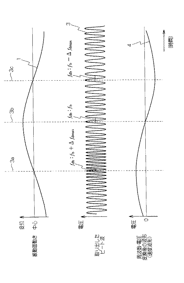
図7は、本実施形態による振動計測例を示す波形図であり、図7(A)は振動変位波形の一例を示す図で、図7(B)はこの場合のビート波の波形例を示す図である。図7(A)に示す例では、変位の増加方向を共振器側としている。このため、符号3cで示す部分にて測定対象物は遠ざかっており、ドップラ周波数Δfdがマイナスであることから、変調ビート周波数fbをプラスとして差を求めるとドップラビート周波数fdbの値は小さくなり、従って、周期は長くなる。変調ビート周波数fbがマイナスの場合には、この振動面動き方向とビート波の周期の関係は逆転する。
符号3bで示す位置にて、測定対象物は折り返すため、速度が「0」となる。このとき、計測によるドップラビート周波数fdbはレーザ駆動電流変調により生じさせた変調ビート周波数fbと等しい。この振動の折り返し点でビート波が崩れないことにより、種々の利点が生じる。まず、測定対象物の振動に複数の振動周期が重畳し、複雑な変位を行ったとしても、変調ビート周波数を中心としてドップラ周波数により周波数変調されるのみであるため、振動の状態を良好に計測することができ、さらに、測定対象物の振動の減衰を計測したい場合であっても、減衰により測定対象物の変位量が「0」となった場合には、ビート波を観測した周波数であるドップラビート周波数が変調ビート周波数になるだけで、ビート波の波形が崩れることがないため、減衰の過程を精度良く計測することができる。
【0044】
図7に示すように、本実施形態による振動計測装置にて測定対象物の振動を計測すると、変調ビート周波数を中心周波数としてドップラ周波数で変調されたビート波を得ることができる。このビート波をF/V変換すると図7(C)に示す速度変化波形を得ることができ、また、ドップラビート周波数から変調ビート周波数を差し引いて符号を反転させることでドップラ周波数を得ることができるため、速度の方向及び速さを算出することができる。
【0045】
【第1実施例】
<信号補正処理>
図8は、本発明の各実施例に共通する振動計測装置の概略構成例を示すブロック図である。図8に示す例では、振動計測装置は、レーザ光を発振すると共に当該発振した出射光が測定対象物で反射した戻り光と当該戻り光受光時に発振した出射光とを自己混合させるレーザ共振器(レーザダイオード)14と、このレーザ共振器の自己混合により生じたビート波を光電変換するフォトダイオード20とをを有するレーザ部12を備えている。
【0046】
また、振動計測装置は、このレーザ共振器を予め定められた波形及び周期のレーザ駆動電流で駆動制御するレーザ駆動制御部24と、レーザ駆動電流の時間変化によるレーザ光の発振周波数fの変化(df/dt)と出射光の出射から戻り光の受光までの期間τとに応じて共振器14内に生じる出射光と戻り光の周波数差を変調ビート周波数fbとするビート波を検出する信号処理手段21とを備えている。
【0047】
しかも、信号処理手段21が、ビート波の変調ビート周波数fbに重畳する測定対象物の速度に応じたドップラ周波数Δfdの変化を周波数変化波形として生成する周波数変化波形生成部22Aを備えている。また、信号処理手段21は、PD出力信号からビート波を検出するビート波検出回路51と、このビート波検出回路によって検出されたPD出力信号のうちレーザ駆動電流と同様に変化する大きな光強度変化成分を除去する任意波形除去回路52と、この任意波形除去回路52によって変調成分が取り除かれた後に信号を増幅する信号増幅回路53とを備えている。信号増幅回路53によって増幅された信号は、上述したビート波として周波数変化波形生成部22Aに入力される。
【0048】
図9は、第1実施例による駆動電流波形の一例を示す波形図であり、図9(A)はレーザ駆動電流を三角波とした場合の例を示す図で、図9(B)は鋸歯状波とした例を示す図である。レーザ駆動電流の変化量が一定であれば、駆動電流による変調で発生する周波数は一定となるため、測定したビート波のドップラビート周波数fdbが変化すると、測定対象物の速度に応じたドップラ周波数Δfdが変化したことが即座に判り、振動状態の判定が容易となる。従って、駆動電流の波形(時間的変化)は図9(A)又は(B)に示すように一定の傾きを有する直線が周期的に繰り返される波形が好ましい。レーザ駆動電流の除去や、変調ビート周波数fbの算出などの観点から、図9(B)に示す鋸歯状波状の駆動電流波形が扱いやすいが、図9(A)に示す対称的な傾きを有する三角波でもよい。三角波による場合、波形の直線部分の傾きの正負によって、変調ビート周波数の増減も変わるため、ドップラ速度を算出する過程で所定の信号処理が必要となる。従って、信号処理を簡略化するためには、できるだけ1つの傾きで、かつその範囲の長い図9(B)の鋸歯状波が好ましい。
【0049】
図9(A)の三角波を駆動電流とするとき、傾きを正負両方で測定する場合には、波形の傾きの正負に応じて周波数処理を選択する必要がある。図10はこの三角波をレーザ駆動電流波形とする場合の振動情報生成部の構成例を示すブロック図である。例えば、図9(C)に示すように駆動電流の上昇期間又は下降期間に応じてセレクト期間を定める。その時測定したドップラ周波数をセレクト期間に応じた演算器を通すことで一様に処理することができる。
【0050】
図10に示す例では、信号処理手段21は、ビート波信号3の周波数(ドップラビート周波数)fdbを算出する周波数算出部54と、レーザ駆動電流の電流変調による変調ビート周波数fbの値を用いてドップラ周波数Δfdを算出する演算部55と、レーザ駆動電流の波形が三角波である場合には当該三角波の立ち上がり期間と立ち下がり期間とに分けてビート波からドップラ周波数を抽出する期間別信号処理部22Bとを備えている。図10に示す例では、期間別信号処理部22Bは、演算部によって算出されたドップラ周波数Δfdの極性(符号)を反転させる極性反転部56と、図9(C)に示すタイミングに応じてドップラ周波数又は極性が反転されたドップラ周波数を選択するセレクタ57とを備えている。ドップラ周波数Δfdを時系列で出力することで、周波数変化波形を出力する。
【0051】
図11は、本実施例での任意波形除去回路の構成例を示すブロック図であり、図11(A)は概略構成を示す図で、図11(B)はレーザ駆動電圧に基づいてビート波から三角波成分を除去する構成例を示す図である。図11(A)に示す例では、図8に示す任意波形除去回路52は、周波数の高い成分を通過させ直流成分を除去するハイパス・フィルタ63と、このハイパス・フィルタ63を通過した信号のうちレーザ駆動電流と同様に変化する光強度変化成分を除去する三角波成分除去部(駆動電流成分除去部)64とを備えている。三角波成分除去部64は、駆動電流波形が鋸歯状波である場合には鋸歯状波成分除去部として機能する。
【0052】
フォトダイオード20で検出されたレーザの光強度変化(PD出力信号)に伴う電気信号をフィルタ63に通して交流成分のみを取り出す。このときの抽出された信号には駆動電流変化に合わせてレーザの光強度が強弱するため、駆動電流波形に比例した三角波成分が含まれている。ビート波に比べてこの三角波成分が非常に大きいため、信号を増幅する前に三角波成分(鋸歯状波成分)を除去する必要がある。
【0053】
具体的には、駆動電流の三角波や鋸歯状波に相当する三角波電圧を用意し、増幅等により振幅を調整した後、PD出力信号に同期させて差し引くことで、駆動電流成分を除去することができる。図11(B)に示す例では、レーザ駆動制御部24にて生成される三角波電圧波形の電圧をPD出力信号の三角波成分の電圧と略同一となるように調整する電圧調整部65と、PD出力信号の位相を検出すると共に当該検出した位相と電圧調整部65で振幅を調整された信号の位相とを同期させる位相検出・同期合わせ部66と、ハイパス・フィルタを通過したPD出力信号から、位相検出・同期合わせ部にて位相が調整された三角波信号を差し引くことでドップラビート周波数を有するビート波のみを抽出する演算回路67とを備えている。
【0054】
図12は、任意波形除去回路52の他の例を示すブロック図である。図12に示す例では、PD出力信号から三角波成分だけを抽出し、電圧調整及び位相調整を行った後に、信号から三角波成分を差し引いている。図12に示す例では、三角波成分除去部64は、ハイパス・フィルタ63を通過したPD出力信号のうち三角波成分を抽出する三角波抽出部68と、この三角波抽出部68によって抽出された三角波波形の位相及び電圧を調整する位相・電圧調整部69と、ハイパス・フィルタ63を通過したPD出力信号から、位相・電圧調整部69から出力される信号成分を差し引く演算回路67とを備えている。
【0055】
また、ハイパス・フィルタ63の遮断周波数を駆動電流波形の周期に応じて設定することで、PD出力信号から三角波成分を除去することもできる。すなわち、ビート波と駆動電流変化の周波数に差があり、ビート波の方が高い周波数を持つため、ハイパスフィルタ63を用いて信号中の駆動電流変化による三角波成分を除去することができる。
【0056】
図11及び図12に示す例では、PD出力信号に含まれる駆動電流の三角波成分を除去した後、増幅する。このため、ビート波成分のみを広い帯域にて扱うことが可能となる。例えば、デジタル信号に変換する場合には、A/D変換器の分解能を最大限活用することができる。
【0057】
【第2実施例】
<周波数変化算出>
第2実施例では、ビート波から周波数変化波形を算出する構成を詳細に説明する。図13(A)はドップラビート周波数の変化を振動速度変化として出力する構成例を示す図である。ビート波の観測周波数は、ドップラ周波数Δfdと変調ビート周波数fbとの差であるため、変調ビート周波数fbが一定の場合には、ドップラビート周波数の変化は、変調ビート周波数で速度を「0」とする速度変化波形として利用することができる。図13(A)に示す例では、周波数変化波形生成部22Aは、信号増幅回路53にて増幅されたビート波のうち、不定期間等について補正を行う信号補正回路72と、この信号補正回路から出力されるビート波の周波数を電圧に変換するF/V変換素子73とを備えている。図13(A)に示す構成は、アナログ回路にて実現することができるため、測定対象物の振動の異常等をリアルタイムで計測する用途に適している。
【0058】
図13(B)はドップラ周波数Δfdの変化を振動速度変化として出力する例を示す図である。図13(B)に示す例では、ドップラビート周波数fdbの変化ではなく、変調ビート周波数成分fbを取り除いて、ドップラ周波数成分Δfdのみを要素とする周波数変化波形を生成する。図13(B)に示す例では、周波数変化波形生成部22Aは、図13(A)に示す構成に加えて、F/V変換素子73から出力されるドップラビート周波数fdbの変化波形から変調ビート周波数fb分を取り除く演算回路75を備えている。演算回路75は、ドップラ周波数の変化波形や、波長を掛けた速度変化波形や、速度変化波形を積分した変位変化波形等を振動情報として出力する。
【0059】
場合によっては、あらかじめ得られた電流変調による変調ビート周波数を、増幅した信号(ビート波)に掛け合わせ、そのエンベローブを測定することでドップラ周波数を算出しても良い。
【0060】
図14は、本発明の第2実施例での信号処理手段の構成例を示すブロック図である。図14及び図15に示す例では、デジタル信号処理により周波数変化波形を出力する。具体的には、数値化されたビート波の周期をビート波形データから時間的に求める。例えば、ビート波を微分することで波形のピークを判定してピーク間の時間を観測して波形の周期を求める方法や、ビート波そのものが任意の電圧を横切る区間を計測することで波形の周期を求めることができる。
【0061】
ピーク間での周期計測は、中心電圧変動に強い一方、ノイズの影響を受けやすい。ビート波が任意の電圧を横切る区間を計測する例では、中心電圧変動には弱いが、比較的ノイズの影響を受けない。このため、信号の状態によって各手法を選択することで波形の周期を正確に算出することができる。
【0062】
ビート波の微分処理を行う例では、ノイズの影響をなくすため、予め波形を平均化したほうが良い。波形のピークを求める方法は、平均化してノイズを除去した信号を微分し、微分値がゼロラインを正から負へ横切った点をピークとするようにしても良い。場合によっては、微分値がゼロラインを負から正へ横切った点をピークとしてもよい。
【0063】
ノイズ対策としては、微分値がゼロラインを正から負へ横切った点の間隔が、予想しうるビート波の波長よりも短かった場合、次の点までの間隔を累積して周期として計算する方法も有効である。また、微分値がゼロラインを正から負へ横切ったときの傾きが、予想しうる傾きよりも急峻だった場合にノイズと判定してこれを無視するようにしても良い。
【0064】
ビート波の周期を直接求める例では、信号を大きく平均化するなどの手段で信号の中心電圧を求め、その電圧ラインをビート波が正から負(又は、負から正)へ横切った点の間隔を測定する。
【0065】
ビート波を微分した微分ビート波を用いて周波数変化波形を生成する例では、図14に示すように、周波数変化波形生成部22Aが、ビート波を微分する微分機能77と、この微分機能77によって微分された微分ビート波がゼロクロスする周期の変化を周波数変化波形として算出するゼロクロス周期算出機能78とを備える。さらに、ゼロクロス周期算出機能78によって検出された周期の値の逆数を時系列で連続的なデータへ整形する機能を備えると、周波数変化波形(測定対象物の速度変化波形)を生成することができる。
【0066】
図15(A)はビート波の周期を直接求める例を示す図で、図15(B)は微分したビート波の周期を求める例を示す図である。図15(A)に示す例では、ビート波が負から正へゼロクロスする位置を検出することで周期Tを求めている。図15(B)に示す例では、図14に示した構成により、ビート波を微分してその微分ビート波が負から正へゼロクロスする位置を検出することで、ビート波のピークからピークまでの周期Tを求めている。
【0067】
【第3実施例】
<周波数スペクトル算出>
第3実施例では、ビート波を周波数分析する例を中心に説明する。図16は、本発明の第3実施例の構成例を示すブロック図である。図16に示す例では、信号処理手段21が、ビート波のノイズを除去する信号補正部72と、ビート波の周波数スペクトルを求めるフーリエ解析機能81と、このフーリエ解析機能81によって生成された周波数スペクトルのうちビート周波数を中心としたスペクトラム幅に基づいて測定対象物の速度に応じたドップラ周波数の最大値又は最小値を算出するドップラ周波数算出機能82とを備えている。
【0068】
図17は、第3実施例で使用するビート波の周波数スペクトルの例を示すスペクトル図である。理想的な状態におけるビート波の周波数分布は、電流変調によって発生する変調ビート周波数fbを中心として、ドップラ周波数Δfd分シフトした形で観測される。従って、信号をフーリエ解析した時のスペクトラム幅の中心が駆動電流変調による変調ビート周波数fbであり、スペクトラム幅の最小周波数fdbminあるいは最大周波数fdbmaxから変調ビート周波数fbを差し引いた周波数の絶対値が最小ドップラ周波数Δfdminまたは最大ドップラ周波数Δfdmaxである。
【0069】
このため、FFTなどの手法を用いてビート波3をフーリエ解析することで、計測したビート波から変調ビート周波数fbと最大ドップラ周波数Δfdmaxとを特定することができる。最大ドップラ周波数Δfdmaxが判明すると、式(3)を用いて測定対象物の最大移動速度を算出することができる。
【0070】
再度図16を参照すると、信号処理手段は、ビート波の観測周波数fdbと中心変調ビート周波数fbとの差の絶対値を測定対象物の速度に応じたドップラ周波数Δfdとして算出するドップラ周波数算出部80と、このドップラ周波数算出部80によって算出されたドップラ周波数Δfdに基づいて測定対象物の速度を算出する移動速度算出部83とを備えている。ドップラ周波数算出部80は、図16に示す例ではFFTを用いることとしているが、予め算出又は計測した変調ビート周波数をビート波の観測周波数から取り除くことでドップラ周波数を抽出するようにしても良い。
【0071】
【第4実施例】
<複数共振器>
第4実施例では、複数のレーザ共振器を用いることで、レーザ駆動電流波形に応じて生じてしまう不定期間のビート波を用いずに連続した振動計測を可能とする。図18は、本発明の第4実施例の構成例を示すブロック図である。本実施形態による振動計測装置は、レーザ光を発振すると共に当該発振した出射光が測定対象物で反射した戻り光と当該戻り光受光時に発振した出射光とを自己混合させる複数のレーザ共振器90,91と、これら複数のレーザ共振器90,91をそれぞれ予め定められた波形及びそれぞれの位相のレーザ駆動電流で駆動制御するレーザ駆動制御部92と、複数の共振器内に生じる出射光と戻り光の周波数差を変調ビート周波数fbとして測定対象物の移動速度に応じたドップラ周波数Δfdが重畳したビート波をそれぞれ検出する信号処理手段95とを備えている。
【0072】
この信号処理手段95は、複数の共振器90,91でそれぞれ生じるビート波のうちレーザ駆動電流の位相及び周期と関係して変調ビート周波数fdbが不定となる不定期間37となっていない共振器90のビート波を選択するビート波選択部93と、このビート波選択部93によって選択されたビート波に基づいて測定対象物の振動情報を生成する振動情報生成部94とを備えている。
【0073】
図19は、第4実施例での2つのレーザ駆動電流の位相関係を示す波形図である。レーザ駆動電流波形の傾きが変わる部分、すなわち、駆動電流波形のピークでは、電流変化がなくなるため、駆動電流変調によるビート波が発生しない。さらに、実際に三角波又は鋸歯状波波形を生成する場合、波形のピークで瞬時に波形の傾きを変えることは難しいため、ピークの前後で直線性が失われて曲線に近くなる。このため、駆動電流波形のピーク近辺では変調ビート周波数fbが生じないか、または不安定となる。このため、図19に示すように、レーザ駆動電流の位相をずらして測定を行うと、変調ビート周波数fbの不定期間37が重ならず、従って、両方の変調ビート周波数安定期間のビート波を利用することで、連続した振動計測を安定して行うことができる。
【0074】
図20は、第4実施例の詳細構成例を示すブロック図である。図20に示す例では、符号90で示す第1のレーザAと、符号91で示す第2のレーザBとでそれぞれF/V変換を行い、セレクタ93にてビート波の不定期間37を除くようにレーザA,Bを選択している。具体的には、レーザA側では、ビート波のノイズを除去する信号補正回路72Aと、ノイズ除去されたビート波の周期変化を電圧変化に変換するF/V変換素子73Aと、このF/V変換素子73Aから出力される速度変化波形の電圧値を規格化する電圧調整回路65Aとを備えている。レーザB側も同様の構成となっており、それぞれの電圧調整回路65A,Bにより速度変化波形の振幅を同一へと整形している。
【0075】
【第5実施例】
<不定期間>
第5実施例では、レーザを1つとしつつ、不定期間の波形を除去して間欠的に振動を計測する。振動の最大速度の監視を行うような場合に有用である。図21は、本発明の第5実施例の構成例を示すブロック図である。図21に示す例では、信号処理手段21が、ビート波のうちレーザ駆動電流の位相及び周期と関係して変調ビート周波数が不定となる不定期間の不定ビート波を除去する不定期間補正部95と、この不定期間補正部95で補正されたビート波に基づいて測定対象物の振動情報を生成する振動情報生成部94とを備えている。不定期間補正部95は、レーザ駆動電流波形の周期及び位相に応じて不定期間とされているビート波を補正する。例えば、ビート波の値を「0」や、十分に低い周期の波形と置き換える。ビート波の値を「0」とすることで、振動情報生成部94の構成を変更することなく、不定期間でのビート波の変動を除去することができる。
【0076】
図22は、第5実施例での安定期間内のビート波の一例を示す波形図であり、図22(A)は測定対象物が停止している場合のビート波を示す図で、図22(B)は測定対象物が振動している場合のビート波の例を示す図である。図22に示すビート波を連続させると、第4実施例等他の実施例で扱うビート波と同様となる。図22(A)に示す例では、ビート波の振幅が若干変動しているものの、周期は略一定であり、この周期に応じた周波数が変調ビート周波数fdbである。図22(B)に示す例では、この変調ビート周波数がドップラ周波数Δfdで変調されている。長い周期から除々に周期が短くなり、続いて周期が長くなっている。この周波数変化が測定対象物のドップラ周波数成分である。廉価な部品を用いても、変調ビート周波数としてメガヘルツオーダーの高周波数を実現できるため、測定対象物の振動変位や祖速度計測の分解能が大幅に向上する。
【0077】
【発明の効果】
本発明は以上のように構成され機能するので、これによると、変調ビート周波数生成制御手段が、測定対象物の速度に応じて戻り光に重畳するドップラ周波数Δfdと比較して高い周波数の変調ビート周波数fbをビート波に含ませるため、測定対象物が静止している状態でも変調ビート周波数fbのビート波を生じさせることができ、そして、測定対象物のドップラ周波数Δfdが、変調ビート周波数fbとの和としてビート波に重畳するため、変調ビート周波数を一定とする場合にはビート波の観測周波数(ドップラビート周波数fdb)の変化がドップラ周波数Δfdの変化を表し、従って、ビート波の観測によるドップラビート周波数fdbの変化波形を速度変化波形として扱うことができ、さらに、ビート波の数だけドップラ周波数Δfdを計測することができるため、変調ビート周波数fbを高く設定することで振動計測の分解能を向上させることができ、特に、従前の発振周波数の半分の長さ(λ/2)を単位とする変位量や速度の算出と比較して大幅に解像度を向上させることができ、従って、従来安定した測定が困難であった微少周期の振動や変位量の微少な変化を精度良く計測することができ、一方、λ/2の長さと比較して変位量が大きく測定対象物の振動周期に対して多すぎるビート波が生じていた場合に対しては、変調ビート周波数fbを低く設定することにより測定対象物の振動周期に対するビート波の数を調整することができ、このように、変調ビート周波数fbを可変とすることで計測精度の向上とデータ量の削減を必要な範囲で調整することができ、さらに、測定対象物が静止している状態でも変調ビート周波数のビート波が生じることから、測定対象物が、複数の振動周期が重畳した複雑な振動をしている場合であっても移動方向の折り返しや速度をビート波の観測周波数(ドップラビート周波数)の変化から計測することができ、また、測定対象物が静止してもビート波が崩れないため、振動の減衰の状態を良好に計測することができ、このようにレーザ発振波長に依存せずに高精度に測定対象物の振動状態を計測することができる、という従来にない優れた振動計測装置及び方法を提供することができる。
【図面の簡単な説明】
【図1】本発明の一実施形態の構成を示すブロック図である。
【図2】図1に示した構成のレーザ部の詳細構成を示す説明図である。
【図3】図1に示した構成を使用して振動情報を生成する工程例を示すフローチャートである。
【図4】本実施形態の動作原理を説明するための波形図であり、図4(A)は振動変位波形の一例を示す図で、図4(B)はドップラ周波数変化波形(速度変化波形)の一例を示す図で、図4(C)は出射光と戻り光の位相差を例示する図で、図4(D)は図4(C)に示す位相差に応じて生じたレーザ光の周波数差を変調ビート周波数とするビート波の一例を示す図で、図4(E)は測定対象物が停止している場合のビート波の周波数を例示する図である。
【図5】図1に示す構成での各種周波数を例示する説明図である。
【図6】本実施形態での光路長設定手段の構成例を示す説明図であり、図6(A)は光路長設定手段として複数のミラーを用いる例を示す図で、図6(B)は光路長設定手段として光ファイバを用いた例を示す図である。
【図7】本実施形態による振動計測例を示す波形図であり、図7(A)は振動変位波形の一例を示す図で、図7(B)はこの場合のビート波の波形例を示す図で、図7(C)はこのビート波をFV変換した周波数変化波形(速度変化波形)の一例を示す図である。
【図8】本発明の実施例の概略構成例を示すブロック図である。
【図9】第1実施例による駆動電流波形の一例を示す波形図であり、図9(A)はレーザ駆動電流を三角波とした場合の例を示す図で、図9(B)は鋸歯状波とした例を示す図で、図9(C)は三角波を選択的に処理する例を示す図である。
【図10】本実施例での振動情報生成部の構成の一例を示すブロック図である。
【図11】本実施例での任意波形除去回路の構成例を示すブロック図であり、図11(A)は概略構成を示す図で、図11(B)はレーザ駆動電圧に基づいてビート波から三角波成分を除去する構成例を示す図である。
【図12】本実施例での任意波形除去回路の他の例を示すブロック図である。
【図13】本実施例でのビート波から振動速度波形を生成する構成例を示すブロック図であり、図13(A)はドップラビート周波数の変化を振動速度変化として出力する構成例を示す図で、図13(B)はドップラ周波数の変化を振動速度変化として出力する例を示す図である。
【図14】本発明の第2実施例での信号処理手段の構成例を示すブロック図である。
【図15】第2実施例での処理を説明するための波形図であり、図15(A)はビート波の周期を直接求める例を示す図で、図15(B)は微分したビート波の周期を求める例を示す図である。
【図16】本発明の第3実施例の構成例を示すブロック図である。
【図17】第3実施例で使用するビート波の周波数スペクトルの例を示すスペクトル図である。
【図18】本発明の第4実施例の構成例を示すブロック図である。
【図19】第4実施例での2つのレーザ駆動電流の位相関係を示す波形図である。
【図20】第4実施例の詳細構成例を示すブロック図である。
【図21】本発明の第5実施例の構成例を示すブロック図である。
【図22】第5実施例での安定期間内のビート波の一例を示す波形図であり、図22(A)は測定対象物が停止している場合のビート波を示す図で、図22(B)は測定対象物が振動している場合のビート波の例を示す図である。
【符号の説明】
8 変調ビート周波数生成制御手段
10 測定対象物
12 レーザ部
14 レーザダイオード(LD)
20 フォトダイオード(PD)
21 信号処理手段
22 振動情報生成部
22A 周波数変化波形生成部(又は、振動速度波形生成部)
22B 期間別信号処理部
24 レーザ駆動制御部
26 鋸歯状波生成機能
28 三角波生成機能[0001]
BACKGROUND OF THE INVENTION
The present invention relates to a vibration measuring method and a frequency measuring device, and more particularly to a vibration measuring method and a frequency measuring device for measuring a vibration state of a measurement object using a self-mixing type laser Doppler vibrometer.
The present invention can be applied to various fields for performing vibration analysis. Specifically, engine vibration analysis, vehicle body propagation vibration analysis, vehicle interior noise analysis, and muffler vibration analysis. There are various applications in other manufacturing fields. It can also be used for maintenance such as detection of plant vibrations using motors and leak diagnosis of water pipes and gas pipes. Furthermore, it can also be applied to the agricultural field, such as determination of sugar content by percussion sound of large fruits such as Saijo.
Further, in the present invention, a vibration period with a minute amplitude such as 200 [nm] and a change in speed of the vibration surface can be measured, so that an inspection and calibration device for a vibration generator and an abnormal vibration of a power device that operates for a long time are used. It can be applied to detection devices. As an inspection / calibration apparatus, for example, it can be used for inspection of the frequency of a crystal oscillator or an ultrasonic oscillator, or for calibration of a function generator. Further, the abnormal vibration detection device can be used for an inspection device for defects generated when vibration energy does not propagate efficiently, such as resonance in a semiconductor manufacturing device using high-frequency vibration, or for tool breakage detection such as a drill.
For this reason, hereinafter, the “measurement object” refers to an object from which vibration measurement is performed from the engine to the tool.
[0002]
[Prior art]
Conventionally, as a means for measuring the vibration frequency of a vibrating object in a non-contact manner, for example, there is a method of obtaining the vibration frequency with a laser displacement meter applying triangulation. Also, a vibration measuring apparatus by the same applicant using a laser Doppler vibrometer is disclosed in Japanese Patent Application Laid-Open No. 11-287699. In the technique described in this publication, a beat wave due to the difference between the frequency of the emitted light and the frequency of the return light on which the Doppler frequency corresponding to the speed of the measurement object is superimposed is detected, and the measurement object is detected based on the beat wave. Displacement and speed change are detected.
[0003]
The technique described in this publication uses the fact that one beat wave is generated when the object to be measured is displaced by half the length (λ / 2) of the oscillation wavelength λ of the beat wave. The amount of displacement was calculated based on And since the amount of displacement of the measuring object is less than λ / 2 at the folded portion of the measuring object, the folding position is determined by utilizing the fact that the waveform is broken and the wavelength of the beat wave becomes long.
[0004]
[Problems to be solved by the invention]
However, in the above conventional example, since the accuracy of vibration measurement depends on the oscillation wavelength of the laser, the displacement amount less than λ / 2 and the state of minute high frequency vibration where the vibration amplitude is less than λ / 2 are good. It was inconvenient that it was difficult to measure. In addition, since various signal processes are required to determine the folding position, there is a disadvantage that the number of processes becomes enormous when the frequency of the measurement object is high. Also, when the measurement object is not a single vibration but a vibration in which a plurality of vibrations are related in a complicated manner, it is difficult to accurately calculate the vibration state depending on the method for determining the folding position. There was an inconvenience.
[0005]
OBJECT OF THE INVENTION
The present invention improves the inconvenience of the conventional example, and in particular, provides a vibration measuring apparatus and method that can measure the vibration state of a measurement object with high accuracy without depending on the laser oscillation wavelength. For that purpose.
[0006]
[Means for Solving the Problems]
Therefore, in the present invention, laser resonance that oscillates laser light and generates beat waves by self-mixing the return light reflected by the measurement object and the emitted light oscillated when the return light is received. By means of a modulation beat frequency generation control means for generating a beat wave having a higher modulation beat frequency than the Doppler frequency superimposed on the return light according to the speed of the measurement object, and self-mixing in the laser resonator Signal processing means for performing signal processing on the generated beat wave and outputting the processing result as vibration information. The signal processing means includes a vibration information generation unit that generates vibration information from the beat wave as a frequency change due to the Doppler frequency centered on the modulation beat frequency. Thus, the above-described purpose is achieved.
[0007]
In the laser resonator, the return light shifted by the Doppler frequency according to the velocity of the measurement object and the outgoing light upon receiving the return light are self-mixed to generate a beat wave. At this time, the modulation beat frequency generation control means generates a higher modulation beat frequency in the beat wave than the Doppler frequency superimposed on the return light according to the speed of the measurement object. For example, the modulation beat frequency generation control means may be configured to provide a laser resonator with a laser drive current that changes the oscillation frequency of the laser resonator, or by physically displacing the laser resonator at a constant speed. You may make it produce Doppler frequencies other than the moving speed according to the speed of a measuring object as a modulation beat frequency.
[0008]
Since the modulation beat frequency generation control means (or laser drive control means) generates a modulation beat frequency in the beat wave by self-mixing, the frequency of the beat wave (the Doppler beat frequency or the actually observed observation frequency of the beat wave) is The sum of the modulation beat frequency and the Doppler frequency corresponding to the speed of the measurement object. When the measurement object is oscillating, the Doppler frequency changes according to the speed of the measurement object. Therefore, the Doppler frequency is “0” at the position where the moving direction of the measurement object turns back. At this time, the Doppler beat frequency (observation frequency) of the beat wave is a modulation beat frequency generated by the modulation beat frequency generation control means. Since the observation frequency of the beat wave at the turn-back position is the modulation beat frequency, the beat wave waveform does not collapse at the turn-back position.
[0009]
When the moving direction is reversed and accelerated at the return position of the measurement object, the Doppler frequency changes accordingly. In the case of sine vibration, it is the fastest at the center position of vibration. Therefore, the Doppler beat frequency changes according to the change of the Doppler frequency around the modulation beat frequency. Therefore, the beat wave can be considered as a signal frequency-modulated with a Doppler frequency using the modulation beat frequency as a carrier frequency. By increasing the modulation beat frequency, which is the carrier frequency, it is possible to capture a minute change in the Doppler frequency, which means that the accuracy is determined regardless of the oscillation wavelength of the laser resonator. For example, when measuring the vibration of a measurement object that vibrates at a certain frequency, if the modulation beat frequency is 10 times the vibration frequency, a beat wave for 10 periods can be obtained for one period of the measurement object. Ten pieces of Doppler frequency information can be obtained.
[0010]
The signal processing means generates vibration information based on the beat wave. Since the beat wave itself is a signal that is frequency-modulated according to the velocity of the measurement object, it is useful as vibration information. The waveform obtained by frequency-voltage conversion of the beat wave is a change waveform of the Doppler frequency centered on the modulation beat frequency, and this is a speed change waveform. Differentiating the speed change waveform, the acceleration change waveform can be integrated to obtain a displacement change waveform, and the period of the speed change waveform becomes the vibration period. Further, when the modulation beat frequency is subtracted from the Doppler beat frequency, the Doppler frequency is obtained. The speed can be obtained from the Doppler frequency and the laser oscillation wavelength.
[0011]
DETAILED DESCRIPTION OF THE INVENTION
Hereinafter, embodiments of the present invention will be described with reference to the drawings. FIG. 1 is a block diagram showing a configuration of an embodiment of the present invention. The vibration measuring apparatus according to the present embodiment generates a beat wave by oscillating laser light and self-mixing the return light reflected by the measurement object and the emitted light oscillated when the return light is received. A
[0012]
In the example shown in FIG. 1, the modulation beat frequency generation control means 8 includes a laser
[0013]
FIG. 2 is an explanatory diagram showing the configuration of the vibration measuring apparatus centering on the detailed configuration of the
[0014]
The
[0015]
FIG. 3 is a flowchart illustrating a processing example for generating vibration information using the configuration illustrated in FIGS. 1 and 2. In the example shown in FIG. 3, a predetermined target modulation beat frequency fb obj The waveform and period of the drive current to the laser resonator are set based on (Step S1, drive current waveform setting step). Also, target modulation beat frequency fb obj The distance from the
[0016]
Thus, in the present embodiment, the target modulation beat frequency fb depends on the upper limit of the frequency to be measured and how many beat waves (Doppler frequency values) are obtained in one cycle of the measurement object. obj Set. Target modulation beat frequency fb obj When the optical path length L to the measurement object is constant, the actual modulation beat frequency fb can be changed by adjusting the rate of change (df / dt) of the laser drive current. Therefore, the optical path length L is determined and the target modulation beat frequency fb obj Is given, it is preferable to change the period (slope) of the laser drive current.
[0017]
When the drive current waveform is set in step S1, laser light is subsequently emitted (step S2, laser light emission step). Then, after the outgoing light round-trip time τ, the return light is received (step S3, return light receiving step). That is, in the return light receiving step S3, a part of the return light emitted in the laser light emitting step S2 and reflected by the
[0018]
Subsequently, the Doppler frequency (Δfd) corresponding to the frequency difference (modulation beat frequency: fb) between the return light received in the return light receiving step S3 and the outgoing light at the time of receiving the return light and the moving speed of the measurement object. ) To detect a beat wave having a Doppler beat frequency (fdb) that is the sum of the above (step S4, beat wave detection step). The observation frequency of the beat wave actually observed in the beat wave detection step S4 is the Doppler beat frequency (fdb), and the Doppler beat frequency fdb is fdb = | ± Δfd + fb |.
[0019]
Subsequently, vibration information is generated based on the beat wave having the Doppler beat frequency fdb (step S5, vibration information generation step).
[0020]
This will be described in detail below.
[0021]
<Measurement principle>
The relational expression for explaining the operation principle in this embodiment is as follows.
[0022]
[Expression 1]
Now, the relationship between the Doppler frequency Δfd and the velocity V of the vibration surface of the measurement object is expressed by Equation (1), where the laser oscillation wavelength is λ. Δfd is a Doppler frequency, which is the difference between the frequency f of the emitted light and the frequency fd of the return light modulated by the Doppler effect. When a laser beam oscillated continuously with a constant driving current is applied to an object to be measured and a beat wave is generated by a self-mixing method, the frequency of the observed beat wave is the Doppler frequency Δfd itself. When equation (1) is integrated, the relationship between the wave number ν of the beat wave and the displacement amount is expressed by equation (2). Conventionally, the displacement amount of the vibration surface is calculated by counting the number of beat waves with the passage of time and setting the half of the oscillation wavelength (λ / 2) as the minimum displacement amount. Further, since the frequency of the beat wave is the Doppler frequency Δfd, the vibration velocity V can be calculated based on the equation (3) by obtaining the observation frequency of the beat wave.
[0024]
If the vibration frequency of the measurement object is low, the vibration amplitude is large, and the number of beat waves generated while the vibration surface reciprocates is large. However, since the vibration amplitude tends to decrease when the frequency is high, the beat wave observed by the movement of the vibration surface often falls below one wave. Therefore, in this case, it is difficult to calculate the vibration displacement amount by counting beat waves. It is also difficult to measure the vibration displacement with an accuracy of less than λ / 2.
[0025]
In the present embodiment, a state in which a beat wave is generated based on a predetermined reference, and the Doppler frequency Δfd is superimposed on the reference modulation beat frequency fb, the resolution based on the oscillation wavelength is changed to the resolution at the reference modulation beat frequency. Change to As a result, the measurement accuracy can be increased as compared with the measurement based on the oscillation wavelength. Therefore, in the present embodiment, a displacement amount less than λ / 2 can be calculated, and the vibration state of the measurement object having a high frequency and a small amplitude can be measured.
[0026]
In order to generate the reference modulation beat frequency fb, a frequency difference is generated between the outgoing light and the return light. For example, when the
[0027]
The
[0028]
When the laser oscillation wavelength is changed at a constant rate, the light reflected and scattered by the
[0029]
When the frequency of the emitted light is f and the optical frequency change rate by changing the laser drive current is df / dt, the distance to the measurement object (external cavity length) is L, and the speed of the laser light in the measurement environment And C is the modulation beat frequency fb when the measurement object is stationary is expressed by equation (4). When both sides of the relational expression between the frequency f and the wavelength λ of the emitted light are differentiated and the optical frequency change rate df / dt is expressed by the wavelength change rate, Equation (5) is obtained. Substituting equation (5) into equation (4) and rearranging results in equation (6). The outgoing light round-trip time is τ = (2L / C), and the wavelength change rate can be approximated by the difference between the wavelength λ1 when the laser light is emitted and the wavelength λ2 of the outgoing light when the return light is received, and the equation (7) is derived.
[0030]
Accordingly, it is assumed that the laser light emitted from the laser resonator oscillating at the wavelength λ1 at an arbitrary time t1 is reflected and scattered by the surface of the measurement object at a distance L and returned to the resonator at the time t2. . When the laser drive current is changed at a constant rate, the wavelength of the laser oscillating at time t2 is λ2. In the resonator, the laser beam oscillating at λ2 and the fed back laser beam of λ1 are self-mixed. When the light from the resonator at this time is received by the photodiode, a beat wave corresponding to the wavelength difference is detected as a change in light intensity due to interference between λ1 and λ2. Thus, the modulation beat frequency determined by the increase rate of the laser drive current, the optical frequency change rate df / dt, and the outgoing light round trip time τ (or the distance L to the measurement object and the speed C of the laser light). fb can be generated when the measurement object is stationary (for example, when the vibration is turned in the moving direction).
[0031]
The distance L to the object to be measured varies depending on the movement of the vibration surface. The distance Lext (external resonator length) when the object to be measured is stationary is about 150 [mm], and the vibration displacement Xm is 1 [ μm], it is not necessary to consider the influence on the amount of change as L≈Lext.
[0032]
When a beat wave is generated at the modulation beat frequency fb while the measurement object is stationary, if the surface of the measurement object has velocity, the observation frequency (Doppler beat frequency) fdb of the beat wave is equal to the observation beat frequency fb and the Doppler This is the sum of the frequency Δfd (Equation (8)). When the measurement object is stationary, the Doppler frequency Δfd is “0”, so the Doppler beat frequency fdb = fb. When the modulation beat frequency fb is sufficiently high as in the equation (8), the Doppler beat frequency fd is a frequency shifted by the Doppler frequency Δfd with respect to the modulation beat frequency fb.
[0033]
Assuming that the modulation beat frequency fb is constant, a change in the Doppler beat frequency fdb of the beat wave detected by the
[0034]
This operation principle will be described again with reference to waveforms. FIG. 4A is a waveform diagram showing an example of a vibration displacement waveform. Here, the increasing direction of the vibration displacement is the
[0035]
4C to 4E are waveform diagrams for explaining the generation of the modulation beat frequency fb. Here, it is assumed that the measurement object is stationary. The waveform indicated by
[0036]
As shown in FIG. 4C, the relationship between the emission light frequency and the return light frequency is reversed at the peak and bottom of the laser drive current. In addition, after the peak of the laser drive current, there is no difference between the output light frequency and the return light frequency, and the modulation beat frequency is “0” or reversed, which is not constant. In this specification, a period in which the modulation beat frequency is not constant is referred to as an
[0037]
With reference to FIG. 5, a process of generating a beat wave in which a Doppler frequency component and a modulated beat frequency component are superimposed will be described. FIG. 5 is a diagram for qualitatively explaining the relationship between the frequencies, and does not accurately show the relationship between the magnitudes of the frequencies. This is the case where the measurement object is moving away, the Doppler frequency Δfd is negative, f1> fd, and fdb> fb. At time t1, emitted light 32 having a frequency f1 is emitted from the
[0038]
Further, since the laser drive current is changed, the emitted light frequency at time t2 changes to f2. The difference between the outgoing light frequency f2 when receiving the return light and the outgoing light frequency f1 is the modulation beat frequency fb, and this modulation beat frequency is defined by equations (4), (7), and the like.
[0039]
The two waves actually mixed in the
[0040]
When the vibration period and vibration speed are more important than the vibration direction, the Doppler beat frequency change waveform may be treated as a speed change waveform regardless of the moving direction of the vibration surface of the measurement object.
[0041]
In this way, the Doppler frequency Δfd itself is not used as a beat wave, but a beat wave having a Doppler beat frequency fdb obtained by shifting the modulation beat frequency by the Doppler frequency is generated. The Doppler frequency Δfd can be obtained, and therefore the vibration speed and vibration cycle can be accurately measured. Then, the modulation beat frequency fb is considered as the carrier frequency of the Doppler frequency Δfd, and the modulation beat frequency fb is set according to the vibration period of the measurement object, the upper limit frequency to be measured, etc. Therefore, the wave number of the beat wave to be detected can be adjusted, so that it is possible to arbitrarily select the measurement accuracy and the amount of data necessary for the measurement.
[0042]
FIG. 6 is an explanatory diagram illustrating a configuration example of the optical path length setting unit in the present embodiment, and FIG. 6A is a diagram illustrating an example in which a plurality of mirrors are used as the optical path length setting unit, and FIG. These are figures which show the example using an optical fiber as an optical path length setting means. As shown in Expression (4), the modulation beat frequency fb depends on the optical path length L. On the other hand, since the modulation beat frequency fb generated by the drive current modulation needs to be set sufficiently higher than the Doppler frequency Δfd, there is a case where it is desired to increase the optical path length L. When there is no distance to the measurement object, the optical path length L can be adjusted by the
[0043]
FIG. 7 is a waveform diagram illustrating an example of vibration measurement according to the present embodiment, FIG. 7A is a diagram illustrating an example of a vibration displacement waveform, and FIG. 7B is a waveform example of a beat wave in this case. FIG. In the example shown in FIG. 7A, the increasing direction of displacement is the resonator side. For this reason, the object to be measured is moving away from the portion indicated by
At the position indicated by the
[0044]
As shown in FIG. 7, when the vibration of the measurement object is measured by the vibration measuring apparatus according to the present embodiment, a beat wave modulated at the Doppler frequency with the modulated beat frequency as the center frequency can be obtained. When this beat wave is F / V converted, the speed change waveform shown in FIG. 7C can be obtained, and the Doppler frequency can be obtained by subtracting the modulation beat frequency from the Doppler beat frequency and inverting the sign. Therefore, the direction and speed of speed can be calculated.
[0045]
[First embodiment]
<Signal correction processing>
FIG. 8 is a block diagram showing a schematic configuration example of a vibration measuring apparatus common to the embodiments of the present invention. In the example shown in FIG. 8, the vibration measuring device oscillates laser light and self-mixes the return light reflected by the measurement object and the emitted light oscillated when the return light is received. The
[0046]
In addition, the vibration measuring apparatus includes a laser
[0047]
Moreover, the signal processing means 21 includes a frequency change
[0048]
FIG. 9 is a waveform diagram showing an example of a drive current waveform according to the first embodiment. FIG. 9A is a diagram showing an example in which the laser drive current is a triangular wave, and FIG. 9B is a sawtooth shape. It is a figure which shows the example made into the wave. If the amount of change in the laser drive current is constant, the frequency generated by modulation by the drive current is constant, so if the Doppler beat frequency fdb of the measured beat wave changes, the Doppler frequency Δfd corresponding to the speed of the measurement object It is immediately known that has changed, and the vibration state can be easily determined. Accordingly, the waveform of the drive current (temporal change) is preferably a waveform in which a straight line having a certain slope is periodically repeated as shown in FIG. 9 (A) or (B). From the viewpoint of removing the laser drive current and calculating the modulation beat frequency fb, the sawtooth wave drive current waveform shown in FIG. 9B is easy to handle, but has a symmetrical slope shown in FIG. 9A. A triangular wave may be used. In the case of a triangular wave, the increase / decrease of the modulation beat frequency also changes depending on whether the slope of the straight line portion of the waveform is positive or negative, so that predetermined signal processing is required in the process of calculating the Doppler velocity. Therefore, in order to simplify the signal processing, the sawtooth wave of FIG. 9B having a single slope as long as possible and having a long range is preferable.
[0049]
When the triangular wave in FIG. 9A is used as the drive current, when measuring the slope in both positive and negative directions, it is necessary to select frequency processing according to the positive and negative of the slope of the waveform. FIG. 10 is a block diagram showing a configuration example of a vibration information generation unit when this triangular wave is used as a laser drive current waveform. For example, as shown in FIG. 9C, the selection period is determined in accordance with the rising or falling period of the drive current. The Doppler frequency measured at that time can be processed uniformly by passing through an arithmetic unit corresponding to the selection period.
[0050]
In the example shown in FIG. 10, the signal processing means 21 uses a
[0051]
FIG. 11 is a block diagram showing a configuration example of the arbitrary waveform removal circuit in this embodiment, FIG. 11A is a diagram showing a schematic configuration, and FIG. 11B is a beat wave based on the laser drive voltage. It is a figure which shows the structural example which removes a triangular wave component from. In the example shown in FIG. 11A, the arbitrary
[0052]
An electric signal accompanying a change in the light intensity of the laser (PD output signal) detected by the
[0053]
Specifically, a triangular wave voltage corresponding to a triangular wave or sawtooth wave of the drive current is prepared, and after adjusting the amplitude by amplification or the like, the drive current component can be removed by subtracting in synchronization with the PD output signal. it can. In the example shown in FIG. 11B, a
[0054]
FIG. 12 is a block diagram illustrating another example of the arbitrary
[0055]
Also, the triangular wave component can be removed from the PD output signal by setting the cutoff frequency of the high-
[0056]
In the example shown in FIGS. 11 and 12, the triangular wave component of the drive current included in the PD output signal is removed and then amplified. For this reason, it becomes possible to handle only the beat wave component in a wide band. For example, when converting to a digital signal, the resolution of the A / D converter can be utilized to the maximum extent.
[0057]
[Second embodiment]
<Frequency change calculation>
In the second embodiment, a configuration for calculating a frequency change waveform from a beat wave will be described in detail. FIG. 13A is a diagram illustrating a configuration example in which a change in Doppler beat frequency is output as a change in vibration speed. The observed frequency of the beat wave is the difference between the Doppler frequency Δfd and the modulation beat frequency fb. Therefore, when the modulation beat frequency fb is constant, the change in the Doppler beat frequency is “0” at the modulation beat frequency. It can be used as a speed change waveform. In the example shown in FIG. 13A, the frequency change
[0058]
FIG. 13B is a diagram illustrating an example in which a change in Doppler frequency Δfd is output as a change in vibration speed. In the example shown in FIG. 13B, the modulation beat frequency component fb is removed instead of the Doppler beat frequency fdb, and a frequency change waveform having only the Doppler frequency component Δfd as an element is generated. In the example shown in FIG. 13B, the frequency
[0059]
In some cases, the Doppler frequency may be calculated by multiplying a modulated beat frequency obtained by current modulation in advance with an amplified signal (beat wave) and measuring the envelope.
[0060]
FIG. 14 is a block diagram showing a configuration example of the signal processing means in the second embodiment of the present invention. In the example shown in FIGS. 14 and 15, a frequency change waveform is output by digital signal processing. More specifically, the digitized beat wave cycle is obtained temporally from the beat waveform data. For example, the waveform peak is determined by differentiating the beat wave and the waveform period is determined by observing the time between the peaks, or the waveform period is measured by measuring the section where the beat wave itself crosses an arbitrary voltage. Can be requested.
[0061]
Period measurement between peaks is resistant to fluctuations in the center voltage, but is susceptible to noise. In the example of measuring a section where the beat wave crosses an arbitrary voltage, it is weak against the center voltage fluctuation, but is relatively unaffected by noise. For this reason, the period of the waveform can be accurately calculated by selecting each method according to the state of the signal.
[0062]
In the example of performing beat wave differentiation, it is better to average the waveforms in advance in order to eliminate the influence of noise. As a method of obtaining the peak of the waveform, the signal obtained by averaging and removing the noise may be differentiated, and the peak may be a point where the differential value crosses the zero line from positive to negative. In some cases, the peak may be a point where the differential value crosses the zero line from negative to positive.
[0063]
As a noise countermeasure, if the interval between the points where the differential value crosses the zero line from positive to negative is shorter than the wavelength of the beat wave that can be expected, the interval to the next point is accumulated and calculated as a period Is also effective. Further, if the slope of the differential value crossing the zero line from positive to negative is steeper than the slope that can be expected, it may be determined as noise and ignored.
[0064]
In the example of directly obtaining the beat wave period, the center voltage of the signal is obtained by means such as averaging the signal, and the interval between the points where the beat wave crosses the voltage line from positive to negative (or from negative to positive). Measure.
[0065]
In the example in which the frequency change waveform is generated using the differential beat wave obtained by differentiating the beat wave, the frequency change
[0066]
FIG. 15A is a diagram showing an example of directly obtaining the beat wave period, and FIG. 15B is a diagram showing an example of obtaining the differentiated beat wave period. In the example shown in FIG. 15A, the period T is obtained by detecting the position where the beat wave zero-crosses from negative to positive. In the example shown in FIG. 15B, the beat wave is differentiated and the position where the differential beat wave zero-crosses from negative to positive is detected by the configuration shown in FIG. The period T is obtained.
[0067]
[Third embodiment]
<Frequency spectrum calculation>
In the third embodiment, an example of frequency analysis of beat waves will be mainly described. FIG. 16 is a block diagram showing a configuration example of the third embodiment of the present invention. In the example illustrated in FIG. 16, the
[0068]
FIG. 17 is a spectrum diagram showing an example of the frequency spectrum of the beat wave used in the third embodiment. The frequency distribution of the beat wave in an ideal state is observed in a form shifted by the Doppler frequency Δfd around the modulation beat frequency fb generated by current modulation. Therefore, the center of the spectrum width when the signal is Fourier analyzed is the modulation beat frequency fb by the drive current modulation, and the minimum frequency fdb of the spectrum width. min Or maximum frequency fdb max The absolute value of the frequency obtained by subtracting the modulation beat frequency fb from the minimum Doppler frequency Δfd min Or maximum Doppler frequency Δfd max It is.
[0069]
For this reason, the
[0070]
Referring to FIG. 16 again, the signal processing means 80 calculates the absolute value of the difference between the beat wave observation frequency fdb and the center modulation beat frequency fb as the Doppler frequency Δfd corresponding to the velocity of the measurement object. And a moving speed calculation unit 83 that calculates the speed of the measurement object based on the Doppler frequency Δfd calculated by the Doppler frequency calculation unit 80. In the example shown in FIG. 16, the Doppler frequency calculation unit 80 uses FFT, but the Doppler frequency may be extracted by removing the modulation beat frequency calculated or measured in advance from the observed frequency of the beat wave.
[0071]
[Fourth embodiment]
<Multiple resonators>
In the fourth embodiment, by using a plurality of laser resonators, it is possible to perform continuous vibration measurement without using irregular beat waves generated according to the laser drive current waveform. FIG. 18 is a block diagram showing a configuration example of the fourth embodiment of the present invention. The vibration measuring apparatus according to the present embodiment oscillates laser light, and a plurality of
[0072]
The signal processing means 95 includes a
[0073]
FIG. 19 is a waveform diagram showing the phase relationship between two laser drive currents in the fourth embodiment. At the portion where the slope of the laser drive current waveform changes, that is, at the peak of the drive current waveform, no current change occurs, so no beat wave due to drive current modulation occurs. Further, when a triangular wave or a sawtooth waveform is actually generated, it is difficult to change the slope of the waveform instantaneously at the peak of the waveform, so that the linearity is lost before and after the peak and becomes close to a curve. For this reason, the modulation beat frequency fb does not occur or becomes unstable near the peak of the drive current waveform. For this reason, as shown in FIG. 19, when the measurement is performed with the phase of the laser drive current shifted, the
[0074]
FIG. 20 is a block diagram showing a detailed configuration example of the fourth embodiment. In the example shown in FIG. 20, F / V conversion is performed by the first laser A indicated by
[0075]
[Fifth embodiment]
<Indefinite period>
In the fifth embodiment, the vibration is intermittently measured by removing irregular waveforms while using one laser. This is useful when monitoring the maximum speed of vibration. FIG. 21 is a block diagram showing a configuration example of the fifth embodiment of the present invention. In the example shown in FIG. 21, the signal processing means 21 includes an indefinite
[0076]
FIG. 22 is a waveform diagram showing an example of a beat wave within a stable period in the fifth embodiment, and FIG. 22 (A) is a diagram showing a beat wave when the measurement object is stopped. (B) is a figure which shows the example of a beat wave in case the measuring object is vibrating. When the beat waves shown in FIG. 22 are made continuous, the beat waves handled in other embodiments such as the fourth embodiment are the same. In the example shown in FIG. 22A, the amplitude of the beat wave slightly varies, but the period is substantially constant, and the frequency corresponding to this period is the modulation beat frequency fdb. In the example shown in FIG. 22B, this modulation beat frequency is modulated with the Doppler frequency Δfd. The period gradually decreases from the long period, and then the period becomes longer. This frequency change is the Doppler frequency component of the measurement object. Even if inexpensive parts are used, a high frequency on the order of megahertz can be realized as the modulation beat frequency, so that the resolution of the vibration displacement of the measurement object and the measurement of the velocities is greatly improved.
[0077]
【The invention's effect】
Since the present invention is configured and functions as described above, according to this, the modulation beat frequency generation control means has a modulation beat having a frequency higher than the Doppler frequency Δfd superimposed on the return light according to the speed of the measurement object. Since the frequency fb is included in the beat wave, the beat wave of the modulation beat frequency fb can be generated even when the measurement object is stationary, and the Doppler frequency Δfd of the measurement object is equal to the modulation beat frequency fb. Therefore, if the modulation beat frequency is constant, the change in the beat wave observation frequency (Doppler beat frequency fdb) represents the change in the Doppler frequency Δfd. The change waveform of the beat frequency fdb can be handled as a speed change waveform, and the Doppler frequency Δfd can be measured by the number of beat waves. Therefore, the resolution of vibration measurement can be improved by setting the modulation beat frequency fb high, and in particular, the amount of displacement and speed calculated in units of half the length (λ / 2) of the previous oscillation frequency can be calculated. Compared with this, the resolution can be greatly improved. Therefore, it is possible to accurately measure a minute period of vibration and a minute change in the amount of displacement, which have conventionally been difficult to achieve stable measurement. If the displacement is large compared to the length and there are too many beat waves for the vibration period of the measurement object, the beat for the vibration period of the measurement object can be set by setting the modulation beat frequency fb low. The number of waves can be adjusted.In this way, by making the modulation beat frequency fb variable, the measurement accuracy can be improved and the amount of data can be reduced within the required range. Stationary Since a beat wave with a modulated beat frequency is generated even in the state, even if the object to be measured has a complex vibration in which a plurality of vibration periods are superimposed, the folding direction and speed of the moving direction can be set to the beat wave observation frequency ( It can be measured from the change in the Doppler beat frequency), and even if the measurement object is stationary, the beat wave does not collapse, so the state of vibration attenuation can be measured well. It is possible to provide an unprecedented excellent vibration measuring apparatus and method capable of measuring the vibration state of the measurement object with high accuracy without depending on the conventional method.
[Brief description of the drawings]
FIG. 1 is a block diagram showing a configuration of an embodiment of the present invention.
FIG. 2 is an explanatory diagram showing a detailed configuration of a laser unit configured as shown in FIG. 1;
FIG. 3 is a flowchart illustrating an example of a process for generating vibration information using the configuration illustrated in FIG. 1;
4A and 4B are waveform diagrams for explaining the operation principle of the present embodiment. FIG. 4A is a diagram showing an example of a vibration displacement waveform, and FIG. 4B is a Doppler frequency change waveform (speed change waveform). 4 (C) is a diagram illustrating the phase difference between the outgoing light and the return light, and FIG. 4 (D) is a laser beam generated according to the phase difference shown in FIG. 4 (C). FIG. 4E is a diagram illustrating an example of a beat wave frequency when the measurement object is stopped.
FIG. 5 is an explanatory diagram illustrating various frequencies in the configuration shown in FIG. 1;
6 is an explanatory diagram showing a configuration example of an optical path length setting unit in the present embodiment, and FIG. 6 (A) is a diagram showing an example in which a plurality of mirrors are used as the optical path length setting unit, and FIG. These are figures which show the example using an optical fiber as an optical path length setting means.
7 is a waveform diagram showing an example of vibration measurement according to the present embodiment, FIG. 7A is a diagram showing an example of a vibration displacement waveform, and FIG. 7B is a waveform example of a beat wave in this case. FIG. 7C is a diagram showing an example of a frequency change waveform (speed change waveform) obtained by FV converting the beat wave.
FIG. 8 is a block diagram showing a schematic configuration example of an embodiment of the present invention.
FIG. 9 is a waveform diagram showing an example of a drive current waveform according to the first embodiment. FIG. 9A is a diagram showing an example in which the laser drive current is a triangular wave, and FIG. 9B is a sawtooth shape. FIG. 9C is a diagram showing an example of selectively processing a triangular wave.
FIG. 10 is a block diagram illustrating an example of a configuration of a vibration information generation unit in the present embodiment.
11 is a block diagram illustrating a configuration example of an arbitrary waveform removal circuit in the present embodiment, FIG. 11A is a diagram illustrating a schematic configuration, and FIG. 11B is a beat wave based on a laser drive voltage; It is a figure which shows the structural example which removes a triangular wave component from.
FIG. 12 is a block diagram showing another example of an arbitrary waveform removal circuit in the present embodiment.
13 is a block diagram illustrating a configuration example for generating a vibration velocity waveform from a beat wave in the present embodiment, and FIG. 13A is a diagram illustrating a configuration example for outputting a change in Doppler beat frequency as a vibration velocity change. FIG. 13B is a diagram illustrating an example in which a change in Doppler frequency is output as a change in vibration speed.
FIG. 14 is a block diagram showing a configuration example of signal processing means in the second embodiment of the present invention.
FIG. 15 is a waveform diagram for explaining processing in the second embodiment. FIG. 15 (A) is a diagram showing an example of directly obtaining the beat wave period, and FIG. 15 (B) is a differentiated beat wave. It is a figure which shows the example which calculates | requires the period.
FIG. 16 is a block diagram showing a configuration example of a third embodiment of the present invention.
FIG. 17 is a spectrum diagram showing an example of a frequency spectrum of a beat wave used in the third embodiment.
FIG. 18 is a block diagram showing a configuration example of a fourth embodiment of the present invention.
FIG. 19 is a waveform diagram showing a phase relationship between two laser drive currents in the fourth embodiment.
FIG. 20 is a block diagram illustrating a detailed configuration example of a fourth embodiment.
FIG. 21 is a block diagram showing a configuration example of a fifth embodiment of the present invention.
22 is a waveform diagram showing an example of a beat wave within a stable period in the fifth embodiment, and FIG. 22 (A) is a diagram showing a beat wave when the measurement object is stopped, FIG. (B) is a figure which shows the example of a beat wave in case the measuring object is vibrating.
[Explanation of symbols]
8 Modulation beat frequency generation control means
10 Measurement object
12 Laser unit
14 Laser diode (LD)
20 Photodiode (PD)
21 Signal processing means
22 Vibration information generator
22A Frequency change waveform generator (or vibration velocity waveform generator)
22B Signal processing unit by period
24 Laser drive controller
26 Sawtooth wave generation function
28 Triangular wave generation function
Claims (15)
前記信号処理手段は、前記ビート波の周波数変化を前記変調ビート周波数を中心とした前記ドップラ周波数による周波数変化として当該ビート波から振動情報を生成する振動情報生成部を備えたことを特徴とする振動計測装置。A laser resonator that oscillates a laser beam and generates a beat wave by self-mixing the return light reflected by the object to be measured and the emitted light oscillated when the return light is received; and the measurement object Modulation beat frequency generation control means for generating a modulation beat frequency higher in the beat wave than the Doppler frequency superimposed on the return light according to the speed of the object, and self-mixing in the laser resonator Signal processing means for performing signal processing on the beat wave and outputting the processing result as vibration information,
The signal processing means includes a vibration information generation unit that generates vibration information from the beat wave as a frequency change by the Doppler frequency centered on the modulation beat frequency. Measuring device.
前記信号処理手段が、前記ビート波に基づいて、前記変調ビート周波数に重畳する前記測定対象物の速度に応じたドップラ周波数の変化を周波数変化波形として生成する周波数変化波形生成部を備えたことを特徴とする振動計測装置。A laser resonator that oscillates the laser light and self-mixes the return light reflected by the measurement object and the emitted light oscillated when the return light is received, and a predetermined waveform of the laser resonator. And a laser drive control unit that performs drive control with a laser drive current of a period, a change in the oscillation frequency of the laser light due to a time change in the laser drive current, and an outgoing light round-trip time from emission of the emitted light to reception of the return light And a signal processing means for detecting a beat wave having a modulated beat frequency as a frequency difference between outgoing light and return light generated in the resonator according to
The signal processing means includes a frequency change waveform generation unit that generates, as a frequency change waveform, a change in Doppler frequency according to the velocity of the measurement object superimposed on the modulation beat frequency based on the beat wave. A characteristic vibration measurement device.
前記信号処理手段が、前記ビート波の周波数スペクトルを求めるフーリエ解析機能と、このフーリエ解析機能によって生成された周波数スペクトルのうち前記変調ビート周波数を中心としたスペクトラム幅に基づいて前記測定対象物の速度に応じたドップラ周波数の最大値又は最小値を算出するドップラ周波数算出機能とを備えたことを特徴とする振動計測装置。A laser resonator that oscillates the laser light and self-mixes the return light reflected by the measurement object and the emitted light oscillated when the return light is received, and a predetermined waveform of the laser resonator. And a laser drive control unit that performs drive control with a laser drive current of a period, a change in the oscillation frequency of the laser light due to a time change in the laser drive current, and an outgoing light round-trip time from emission of the emitted light to reception of the return light And a signal processing means for detecting a beat wave having a modulated beat frequency as a frequency difference between outgoing light and return light generated in the resonator according to
The signal processing means has a Fourier analysis function for obtaining a frequency spectrum of the beat wave, and a speed of the measurement object based on a spectrum width centered on the modulation beat frequency among frequency spectra generated by the Fourier analysis function. And a Doppler frequency calculation function for calculating a maximum value or a minimum value of a Doppler frequency corresponding to the vibration measurement device.
前記信号処理手段が、前記ビート波の周波数と前記変調ビート周波数との差を前記測定対象物の速度に応じたドップラ周波数として算出するドップラ周波数算出部と、このドップラ周波数算出部によって算出されたドップラ周波数に基づいて前記測定対象物の速度を算出する移動速度算出部とを備えたことを特徴とする振動計測装置。A laser resonator that oscillates the laser light and self-mixes the return light reflected by the measurement object and the emitted light oscillated when the return light is received, and a predetermined waveform of the laser resonator. And a laser drive control unit that performs drive control with a laser drive current of a period, a change in the oscillation frequency of the laser light due to a time change in the laser drive current, and an outgoing light round-trip time from emission of the emitted light to reception of the return light And a signal processing means for detecting a beat wave whose modulation beat frequency is a frequency difference between the outgoing light and the returning light generated in the resonator according to
The signal processing means calculates a difference between the beat wave frequency and the modulated beat frequency as a Doppler frequency corresponding to the velocity of the measurement object, and a Doppler frequency calculated by the Doppler frequency calculation unit. A vibration measurement apparatus comprising: a moving speed calculation unit that calculates a speed of the measurement object based on a frequency.
前記信号処理手段が、前記複数の共振器でそれぞれ生じるビート波のうち前記レーザ駆動電流の位相及び周期と関係して変調ビート周波数が不定となる不定期間となっていない共振器のビート波を選択するビート波選択部と、このビート波選択部によって選択されたビート波に基づいて前記測定対象物の振動情報を生成する振動情報生成部とを備えたことを特徴とする振動計測装置。A plurality of laser resonators that oscillate laser light and self-mix the return light reflected by the measurement object and the emitted light oscillated when the return light is received, and the plurality of laser resonators. A laser drive control unit that performs drive control with a laser drive current having a predetermined waveform and each phase, and a movement of the measurement object using a frequency difference between emitted light and return light generated in the plurality of resonators as a modulation beat frequency Signal processing means for detecting each beat wave on which the Doppler frequency corresponding to the speed is superimposed,
The signal processing means selects a beat wave of a resonator that is not in an indefinite period in which a modulation beat frequency is indefinite in relation to a phase and a period of the laser driving current among beat waves generated in the plurality of resonators, respectively. A vibration measurement device comprising: a beat wave selection unit that performs vibration information generation unit that generates vibration information of the measurement object based on the beat wave selected by the beat wave selection unit.
前記信号処理手段が、前記ビート波のうち前記レーザ駆動電流の位相及び周期と関係して変調ビート周波数が不定となる不定期間の不定ビート波を除去する不定期間補正部と、この不定期間補正部で補正されたビート波に基づいて前記測定対象物の振動情報を生成する振動情報生成部とを備えたことを特徴とする振動計測装置。A laser resonator that oscillates the laser light and self-mixes the return light reflected by the measurement object and the emitted light oscillated when the return light is received, and a predetermined waveform of the laser resonator. And a laser drive control unit that performs drive control with a laser drive current of a period, and a Doppler frequency corresponding to the moving speed of the measurement object is superimposed using a frequency difference between the emitted light and the return light generated in the resonator as a modulation beat frequency. Signal processing means for detecting beat waves,
The signal processing means removes an indefinite period indefinite beat wave in which the modulation beat frequency is indefinite in relation to the phase and period of the laser drive current in the beat wave, and the indefinite period correction unit And a vibration information generation unit that generates vibration information of the measurement object based on the beat wave corrected in step (b).
このビート波検出工程に続いて、前記変調ビート周波数と前記ドップラビート周波数との差に基づいて前記測定対象物の振動情報を生成する振動情報生成工程とを備えたことを特徴とする振動計測方法。A laser beam emitting step of emitting laser light to a measurement object using a laser resonator, and return light which is emitted in this laser beam emission step and reflected by the measurement object through a predetermined optical path length A return light receiving process for receiving a part of the light, a modulation beat frequency that is a frequency difference between the return light received in the return light receiving process and an emitted light at the time of receiving the return light, and a moving speed of the measurement object. A beat wave detecting step for detecting a beat wave having a Doppler beat frequency including a corresponding Doppler frequency, and
A vibration measurement method comprising a vibration information generation step of generating vibration information of the measurement object based on a difference between the modulation beat frequency and the Doppler beat frequency following the beat wave detection step. .
Priority Applications (3)
| Application Number | Priority Date | Filing Date | Title |
|---|---|---|---|
| JP2000069088A JP3671805B2 (en) | 2000-03-13 | 2000-03-13 | Vibration measuring apparatus and method |
| US09/799,617 US6470753B2 (en) | 2000-03-13 | 2001-03-07 | Vibration measuring apparatus and method |
| DE10111974A DE10111974B4 (en) | 2000-03-13 | 2001-03-13 | Device and method for vibration measurement |
Applications Claiming Priority (1)
| Application Number | Priority Date | Filing Date | Title |
|---|---|---|---|
| JP2000069088A JP3671805B2 (en) | 2000-03-13 | 2000-03-13 | Vibration measuring apparatus and method |
Publications (2)
| Publication Number | Publication Date |
|---|---|
| JP2001255202A JP2001255202A (en) | 2001-09-21 |
| JP3671805B2 true JP3671805B2 (en) | 2005-07-13 |
Family
ID=18588041
Family Applications (1)
| Application Number | Title | Priority Date | Filing Date |
|---|---|---|---|
| JP2000069088A Expired - Fee Related JP3671805B2 (en) | 2000-03-13 | 2000-03-13 | Vibration measuring apparatus and method |
Country Status (3)
| Country | Link |
|---|---|
| US (1) | US6470753B2 (en) |
| JP (1) | JP3671805B2 (en) |
| DE (1) | DE10111974B4 (en) |
Cited By (1)
| Publication number | Priority date | Publication date | Assignee | Title |
|---|---|---|---|---|
| CN110186551A (en) * | 2019-06-20 | 2019-08-30 | 厦门大学 | Square wave transforming amplitudes measuring device and method based on self-mixed interference |
Families Citing this family (35)
| Publication number | Priority date | Publication date | Assignee | Title |
|---|---|---|---|---|
| US6892568B2 (en) * | 2003-02-03 | 2005-05-17 | Honda Giken Kogyo Kabushiki Kaisha | Noise detection system and method |
| US7134341B2 (en) * | 2003-04-28 | 2006-11-14 | Zuli Holdings Ltd | Methods and devices for determining the resonance frequency of passive mechanical resonators |
| US8162839B2 (en) * | 2003-08-27 | 2012-04-24 | Microtech Medical Technologies Ltd. | Protected passive resonating sensors |
| US7415883B2 (en) * | 2004-06-28 | 2008-08-26 | Zuli Holdings Ltd | Method for protecting resonating sensors and open protected resonating sensors |
| CN1327200C (en) * | 2004-06-15 | 2007-07-18 | 北京航空航天大学 | Digital laser image vibration measurer |
| US7507203B2 (en) * | 2004-09-21 | 2009-03-24 | Digital Signal Corporation | System and method for remotely monitoring physiological functions |
| JP5172077B2 (en) * | 2005-05-06 | 2013-03-27 | アズビル株式会社 | Distance / speed meter and distance / speed measurement method |
| US7533572B2 (en) * | 2006-08-15 | 2009-05-19 | Siemens Energy, Inc. | High bandwidth fiber optic vibration sensor |
| EP1953567A3 (en) * | 2007-01-25 | 2010-09-22 | Yamatake Corporation | Counting device, distance meter, counting method, and distance measuring method |
| US7649631B2 (en) * | 2007-06-06 | 2010-01-19 | Yamatake Corporation | Distance/speed meter and distance/speed measuring method |
| EP2171811B1 (en) * | 2007-06-27 | 2015-05-20 | Koninklijke Philips N.V. | Optical sensor module and its manufacture |
| JP5096123B2 (en) * | 2007-12-12 | 2012-12-12 | アズビル株式会社 | Distance / speed meter and distance / speed measurement method |
| JP5081776B2 (en) * | 2008-09-22 | 2012-11-28 | アズビル株式会社 | Vibration frequency measuring device and vibration frequency measuring method |
| JP5081778B2 (en) * | 2008-09-25 | 2012-11-28 | アズビル株式会社 | Vibration amplitude measuring apparatus and vibration amplitude measuring method |
| JP5596915B2 (en) * | 2008-10-21 | 2014-09-24 | アズビル株式会社 | Physical quantity sensor and physical quantity measuring method |
| JP5541774B2 (en) * | 2008-12-08 | 2014-07-09 | アズビル株式会社 | Physical quantity sensor and physical quantity measuring method |
| JP5421669B2 (en) * | 2009-06-23 | 2014-02-19 | アズビル株式会社 | Amplitude calculation apparatus and amplitude calculation method |
| JP5426345B2 (en) * | 2009-12-04 | 2014-02-26 | アズビル株式会社 | Vibration amplitude measuring apparatus and vibration amplitude measuring method |
| US8537341B2 (en) | 2010-03-16 | 2013-09-17 | Azbil Corporation | Physical quantity sensor and physical quantity measuring method |
| JP5750788B2 (en) * | 2010-06-15 | 2015-07-22 | 国立大学法人北海道大学 | Method and apparatus for measuring vibration characteristics of structure |
| DE102010030549B4 (en) * | 2010-06-25 | 2016-04-28 | Siemens Aktiengesellschaft | Non-dispersive gas analyzer |
| JP2012125135A (en) | 2010-07-27 | 2012-06-28 | Nihon Densan Seimitsu Kk | Vibration generator |
| US8949085B2 (en) * | 2011-10-28 | 2015-02-03 | General Electric Company | System and method for obtaining and de-noising vibratory data |
| DE102012219254B4 (en) * | 2012-10-22 | 2015-01-29 | Sauer Ultrasonic Gmbh | Supply circuit, supply system, tool actuator, tool |
| US10031246B2 (en) * | 2012-11-15 | 2018-07-24 | The United States Of America As Represented By The Secretary Of The Army | RF-photonic system for acoustic and/or vibrational sensing using optical fiber and method thereof |
| CA2991731A1 (en) | 2014-07-17 | 2016-01-21 | I Sonic Medical Corporation, S.A.S. | Measurement of ocular parameters using vibrations induced in the eye |
| JP6079739B2 (en) * | 2014-09-25 | 2017-02-15 | トヨタ自動車株式会社 | Measuring method of laser scanning speed |
| US10808898B2 (en) * | 2015-03-26 | 2020-10-20 | Tiger Tech Industries | Solar powered light assembly with sensor |
| DE102015217200A1 (en) | 2015-09-09 | 2017-03-09 | Sauer Gmbh | Method and device for determining a vibration amplitude of a tool |
| US11026066B2 (en) * | 2017-09-14 | 2021-06-01 | Airmagnet, Inc. | Determining wireless network device location |
| CN108593768B (en) * | 2018-01-31 | 2020-09-01 | 徐州工程学院 | A welding seam detection platform for silencer pipes in carbon tetrachloride treatment equipment |
| DE102018201735B4 (en) | 2018-02-05 | 2024-11-28 | Carl Zeiss Ag | Device and method for determining a distance of a moving object |
| CN109324115A (en) * | 2018-09-01 | 2019-02-12 | 哈尔滨工程大学 | A method for evaluating liquid-filled pipeline mufflers in reverberation pools |
| CN116848434A (en) * | 2021-02-26 | 2023-10-03 | 三菱电机株式会社 | Signal processing device, signal processing method and laser radar device |
| CN114184271B (en) * | 2021-11-30 | 2023-06-27 | 西安航天动力研究所 | High-frequency vibration mode identification method and system based on motion amplification and digital image correlation |
Family Cites Families (6)
| Publication number | Priority date | Publication date | Assignee | Title |
|---|---|---|---|---|
| US3958881A (en) | 1970-11-18 | 1976-05-25 | Raytheon Company | Method of operating a laser oscillator and amplifier |
| DE4006690C2 (en) | 1990-03-03 | 1994-07-28 | Mesacon Ges Fuer Mestechnik Mb | Method and arrangement for measuring the speed of a moving surface by means of a measuring light beam emanating from a laser |
| US5680212A (en) | 1996-04-15 | 1997-10-21 | National Research Council Of Canada | Sensitive and fast response optical detection of transient motion from a scattering surface by two-wave mixing |
| US5827971A (en) | 1996-05-31 | 1998-10-27 | Lockheed Martin Idaho Technologies Company | Optical vibration detection spectral analysis assembly and method for detecting vibration in an object of interest |
| DE19707773C2 (en) | 1997-02-26 | 2000-05-25 | Kayser Threde Gmbh | Device and method for determining the phase difference between interfering beams |
| JPH11287699A (en) | 1998-03-31 | 1999-10-19 | Suzuki Motor Corp | Vibration measuring device and storage medium storing vibration measuring program |
-
2000
- 2000-03-13 JP JP2000069088A patent/JP3671805B2/en not_active Expired - Fee Related
-
2001
- 2001-03-07 US US09/799,617 patent/US6470753B2/en not_active Expired - Fee Related
- 2001-03-13 DE DE10111974A patent/DE10111974B4/en not_active Expired - Fee Related
Cited By (1)
| Publication number | Priority date | Publication date | Assignee | Title |
|---|---|---|---|---|
| CN110186551A (en) * | 2019-06-20 | 2019-08-30 | 厦门大学 | Square wave transforming amplitudes measuring device and method based on self-mixed interference |
Also Published As
| Publication number | Publication date |
|---|---|
| JP2001255202A (en) | 2001-09-21 |
| DE10111974A1 (en) | 2001-10-11 |
| US6470753B2 (en) | 2002-10-29 |
| DE10111974B4 (en) | 2007-04-12 |
| US20010032514A1 (en) | 2001-10-25 |
Similar Documents
| Publication | Publication Date | Title |
|---|---|---|
| JP3671805B2 (en) | Vibration measuring apparatus and method | |
| JP3680678B2 (en) | Vibration measuring method and frequency measuring device | |
| JP3606067B2 (en) | Vibration measuring method and apparatus | |
| CN102792183B (en) | Physical quantity sensor and physical quantity measuring method | |
| JP2011189407A (en) | Apparatus and method for laser welding | |
| JP2963075B2 (en) | Displacement measuring device and displacement measuring method | |
| JPH10246782A (en) | Laser rangefinder | |
| JP5424602B2 (en) | Laser ultrasonic detection apparatus and laser ultrasonic detection method | |
| JP4071688B2 (en) | Vibration measuring method and apparatus | |
| JP3729105B2 (en) | Vibration measuring apparatus and method, and vibration measuring program | |
| JPH11287859A (en) | Laser rangefinder | |
| JP3584758B2 (en) | Method and apparatus for measuring vibration | |
| JP5854710B2 (en) | Demodulation method for pseudo-heterodyne signals | |
| JP2005062093A (en) | Target sound detection method and apparatus | |
| JP3282746B2 (en) | Semiconductor laser digital vibration displacement measuring device | |
| JP2004271493A (en) | Laser vibrometer | |
| JP2006153477A (en) | Distance measuring device and distance measuring method | |
| JP3774751B2 (en) | Semiconductor laser digital vibration measuring device | |
| JP5596917B2 (en) | Physical quantity sensor and physical quantity measuring method | |
| JP3800911B2 (en) | Waveform analyzer | |
| JP2007017293A (en) | Standing wave ranging device | |
| JPH11326032A (en) | Method and apparatus for measuring vibration and abnormality detection apparatus | |
| JP5848641B2 (en) | Status detection apparatus and method | |
| JP3671806B2 (en) | Vibration measuring method and apparatus | |
| JP2000131133A (en) | Vibration measurement method |
Legal Events
| Date | Code | Title | Description |
|---|---|---|---|
| A977 | Report on retrieval |
Free format text: JAPANESE INTERMEDIATE CODE: A971007 Effective date: 20041014 |
|
| TRDD | Decision of grant or rejection written | ||
| A01 | Written decision to grant a patent or to grant a registration (utility model) |
Free format text: JAPANESE INTERMEDIATE CODE: A01 Effective date: 20050329 |
|
| A61 | First payment of annual fees (during grant procedure) |
Free format text: JAPANESE INTERMEDIATE CODE: A61 Effective date: 20050411 |
|
| S531 | Written request for registration of change of domicile |
Free format text: JAPANESE INTERMEDIATE CODE: R313532 |
|
| R350 | Written notification of registration of transfer |
Free format text: JAPANESE INTERMEDIATE CODE: R350 |
|
| FPAY | Renewal fee payment (event date is renewal date of database) |
Free format text: PAYMENT UNTIL: 20090428 Year of fee payment: 4 |
|
| FPAY | Renewal fee payment (event date is renewal date of database) |
Free format text: PAYMENT UNTIL: 20100428 Year of fee payment: 5 |
|
| FPAY | Renewal fee payment (event date is renewal date of database) |
Free format text: PAYMENT UNTIL: 20110428 Year of fee payment: 6 |
|
| FPAY | Renewal fee payment (event date is renewal date of database) |
Free format text: PAYMENT UNTIL: 20110428 Year of fee payment: 6 |
|
| FPAY | Renewal fee payment (event date is renewal date of database) |
Free format text: PAYMENT UNTIL: 20120428 Year of fee payment: 7 |
|
| FPAY | Renewal fee payment (event date is renewal date of database) |
Free format text: PAYMENT UNTIL: 20120428 Year of fee payment: 7 |
|
| FPAY | Renewal fee payment (event date is renewal date of database) |
Free format text: PAYMENT UNTIL: 20130428 Year of fee payment: 8 |
|
| FPAY | Renewal fee payment (event date is renewal date of database) |
Free format text: PAYMENT UNTIL: 20130428 Year of fee payment: 8 |
|
| FPAY | Renewal fee payment (event date is renewal date of database) |
Free format text: PAYMENT UNTIL: 20140428 Year of fee payment: 9 |
|
| LAPS | Cancellation because of no payment of annual fees |