JP3660696B2 - Spinous process spacer - Google Patents
Spinous process spacer Download PDFInfo
- Publication number
- JP3660696B2 JP3660696B2 JP14480994A JP14480994A JP3660696B2 JP 3660696 B2 JP3660696 B2 JP 3660696B2 JP 14480994 A JP14480994 A JP 14480994A JP 14480994 A JP14480994 A JP 14480994A JP 3660696 B2 JP3660696 B2 JP 3660696B2
- Authority
- JP
- Japan
- Prior art keywords
- spinous process
- section
- process spacer
- spinous
- divided
- Prior art date
- Legal status (The legal status is an assumption and is not a legal conclusion. Google has not performed a legal analysis and makes no representation as to the accuracy of the status listed.)
- Expired - Lifetime
Links
Images


Classifications
-
- A—HUMAN NECESSITIES
- A61—MEDICAL OR VETERINARY SCIENCE; HYGIENE
- A61B—DIAGNOSIS; SURGERY; IDENTIFICATION
- A61B17/00—Surgical instruments, devices or methods
- A61B17/56—Surgical instruments or methods for treatment of bones or joints; Devices specially adapted therefor
- A61B17/58—Surgical instruments or methods for treatment of bones or joints; Devices specially adapted therefor for osteosynthesis, e.g. bone plates, screws or setting implements
- A61B17/68—Internal fixation devices, including fasteners and spinal fixators, even if a part thereof projects from the skin
- A61B17/70—Spinal positioners or stabilisers, e.g. stabilisers comprising fluid filler in an implant
- A61B17/7071—Implants for expanding or repairing the vertebral arch or wedged between laminae or pedicles; Tools therefor
-
- A—HUMAN NECESSITIES
- A61—MEDICAL OR VETERINARY SCIENCE; HYGIENE
- A61B—DIAGNOSIS; SURGERY; IDENTIFICATION
- A61B17/00—Surgical instruments, devices or methods
- A61B17/56—Surgical instruments or methods for treatment of bones or joints; Devices specially adapted therefor
- A61B17/58—Surgical instruments or methods for treatment of bones or joints; Devices specially adapted therefor for osteosynthesis, e.g. bone plates, screws or setting implements
- A61B17/68—Internal fixation devices, including fasteners and spinal fixators, even if a part thereof projects from the skin
- A61B17/70—Spinal positioners or stabilisers, e.g. stabilisers comprising fluid filler in an implant
- A61B17/7062—Devices acting on, attached to, or simulating the effect of, vertebral processes, vertebral facets or ribs ; Tools for such devices
Landscapes
- Health & Medical Sciences (AREA)
- Orthopedic Medicine & Surgery (AREA)
- Life Sciences & Earth Sciences (AREA)
- Neurology (AREA)
- Surgery (AREA)
- Heart & Thoracic Surgery (AREA)
- Engineering & Computer Science (AREA)
- Biomedical Technology (AREA)
- Nuclear Medicine, Radiotherapy & Molecular Imaging (AREA)
- Medical Informatics (AREA)
- Molecular Biology (AREA)
- Animal Behavior & Ethology (AREA)
- General Health & Medical Sciences (AREA)
- Public Health (AREA)
- Veterinary Medicine (AREA)
- Surgical Instruments (AREA)
- Prostheses (AREA)
Description
【0001】
【産業上の利用分野】
本発明は、頸椎の棘突起(椎弓を含む)を正中で縦方向に二分割し、分割した棘突起間に挿入固定する棘突起スペーサに関する。
【0002】
【従来技術及びその問題点】
頸椎症性脊髄症や頸椎後縦靭帯骨化症によって脊髄が圧迫されて起こる障害を取り除くため、従来から脊柱管拡大術が行われ、なかでも棘突起縦割法はしばしば行われ、既に確立された手術法となっている。この方法では、従来、縦割した棘突起間に腸骨から採取した骨片を装着していたが、腸骨採取の負担を患者に与えることになるため、最近では、装着時の水平断面のみを台形形状としたセラミックス製ブロック状体を用いることが試みられてきた。
しかしながら、この従来品は、分割棘突起の実際の形状に適合しているとは言えず、分割棘突起間の間隙への適合性があまり良くなく、その結果、骨吸収が発生したり、スペーサ同士が接触し、頸椎の運動が阻害されることがあった。
【0003】
【発明の目的】
本発明は、分割棘突起との適合性に優れ、固定後の骨吸収が起こらず、しかも隣接するスペーサ同士が接触せず、頸椎の運動を阻害しない棘突起スペーサを提供することを目的とする。
【0004】
【発明の概要】
本発明は、脊柱管拡大術における分割棘突起を拡大した状態を詳細に観察した結果、分割棘突起を開いて脊柱管を拡大すると、頭(上)側と尾(下)側とは均一に拡大せず、頭側が尾側より広く開くという事実を発見してなされたものである。
すなわち、縦割りした分割棘突起の間に挿入して脊柱管を拡大する際に用いる本発明の棘突起スペーサは、水平断面においては脊柱管側の幅が狭い略台形状をなし、かつ、分割棘突起間に渡る縦方向の前額断面においては頭部側の幅が広い略台形状をなすブロック形状を有し、上記水平断面と前額断面における断面台形状はそれぞれ、長辺側から短辺側に至る両端部の角度が40゜以上85゜未満であり、生体親和性セラミックス材料からなることを特徴としている。
この棘突起スペーサには、さらに、水平断面における脊柱管の径方向の外方に位置させて、分割棘突起の外側に位置するフランジを一体に設けて、脊柱管内への脱落をより確実に防止することができる。
【0005】
本発明の棘突起スペーサを構成する生体親和性のセラミックス材料としては、ガラスセラミックス又はCa/P比1.0〜2.0のリン酸カルシウム系化合物が好ましい。本発明に使用しうるCa/P比1.0〜2.0のリン酸カルシウム系化合物としては、ハイドロキシアパタイト、フッ素アパタイト等の各種のアパタイト、第一リン酸カルシウム、第二リン酸カルシウム、リン酸三カルシウム、リン酸四カルシウムなどが挙げられ、これらは単独で又は混合物として使用することができる。原料化合物のスラリーを乾燥した後、500〜800℃で仮焼した後、800〜1400℃で焼成し、得られたブロック状体を所望の形状及び寸法に加工するか、又は上記リン酸カルシウム系化合物の粉体から所望の形状及び寸法を有する圧粉体を作製し、これを上記と同様に焼成することによって製造することができる。
【0006】
本発明において、棘突起スペーサの少なくとも表面部を生体親和性の多孔質セラミックスから構成することにより、周囲の骨組織との親和性がよく、気孔内への骨組織の進入により骨癒合が促進される。多孔質セラミックスは、連続気孔を有するのが好ましい。その気孔径や気孔率には特に制限はないが、通常、気孔径は2〜2000μmであるのが好ましく、気孔率は30〜80%、好ましくは40〜70%である。
【0007】
中心部は、緻密質又は多孔質セラミックスから構成されていてもよく、使用しうるセラミックスとしては、Ca/P比1.0〜2.0のリン酸カルシウム系化合物、アルミナ、チタニア、ジルコニアなどが挙げられ、これらのうちリン酸カルシウム系化合物が好適である。緻密質セラミックスから成る中心部の表面に多孔質の生体親和性材料の層を設ける方法には、特に制限はなく、任意の公知方法を採用することができ、例えば、溶射法、スパッタリング法、含浸法、スプレーコーティング法などが挙げられる。
【0008】
本発明の棘突起スペーサは、上記のように少なくとも表面部が生体親和性の多孔質セラミックスから構成されていればよいが、全体が生体親和性を有する多孔質セラミックスから成るのが好ましい。
【0009】
【発明の実施例】
次に、図面を参照して本発明を実施例に基づいて詳細に説明する。
図1ないし図4は、本発明による棘突起スぺーサ10の第一の実施例を示し、図5ないし図7は、頸椎の棘突起を分割して行なう脊柱管拡大術及び本棘突起スぺーサ10の挿入状態を示している。棘突起の縦割術は、図5に示すように、頸椎(図示例は第4頸椎)20の棘突起21を、正中において切断線22により縦方向に分割して行なう。脊柱管拡大術は、分割棘突起21aを左右(図5ないし図7において左右)に開いて行なうものであるが、本発明者らは、この分割棘突起21aの拡大の際、一対の分割棘突起21aは均一には拡大せず、頭側が尾側より広く開くことを見出した。図7は、その様子を示している。23は椎体、24は脊柱管を示す。
【0010】
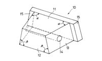
本発明の棘突起スぺーサ10は、開いた分割棘突起21aの間に挿入した状態において、その水平断面(図6)において脊柱管24側の幅が狭い台形形状を呈し、かつ分割棘突起21aの間に渡る縦方向の前額断面においても頭部側の幅が広い台形形状を呈している。すなわち、本発明の棘突起スぺーサ10は、単体で見たときには、平面から見て左右対称の台形11をなし、正面から見て別の左右対称の台形12をなしている。また側面から見ては矩形13をなしている。この棘突起スぺーサ10には、対をなす分割棘突起21aを結ぶ方向の貫通孔14が穿設されている。
【0011】
水平断面における台形11と前額断面における台形12の長辺側から短辺側に至る両端部の角度α、βはともに、10゜以上90゜未満とするのが好ましく、特に40゜以上85゜未満とすることが好ましい。
【0012】
本発明の棘突起スぺーサ10は、図6、図7に示すように、水平断面においては幅の狭い側を脊柱管24側に向け、前額断面においては幅の広い側を頭側に向けて、分割棘突起21aの間に挿入固定される。この際、一対の分割棘突起21aと貫通孔14との間には、固定糸を通す。
【0013】
図8は、本発明の別の実施例を示すもので、第一の実施例の形状に加えて、水平断面における脊柱管24の径方向の外方に位置させて、つまり、分割棘突起21aの外側に位置させて、フランジ15を一体に設けた実施例である。この実施例によれば、本棘突起スぺーサ10が脊柱管24内に脱落するのを確実に防止できる。
【0014】
【発明の効果】
本発明によれば、頸椎脊柱管拡大術を行う際に、縦割した棘突起の間隙内への適合性が極めて良好な棘突起スペーサを提供することができる。本発明の棘突起スペーサを用いると、固定後の骨吸収が発生せず、隣接するスペーサが生理的に配列するため、頸椎の運動が阻害されず、違和感を生じることなく、スムースに頸部を動かすことが可能となる。
【図面の簡単な説明】
【図1】本発明の一実施例を示す棘突起スペーサの斜視図である。
【図2】図1に示した棘突起スペーサの平面図である。
【図3】図1に示した棘突起スペーサの正面図である。
【図4】図1に示した棘突起スペーサの側面図である。
【図5】頸椎の棘突起縦割術を説明する水平断面図である。
【図6】図5の棘突起縦割術によって分割した棘突起を開いてその間に本発明の棘突起スぺーサを挿入した状態を示す水平断面図である。
【図7】同前額断面図である。
【図8】本発明による棘突起スぺーサの別の実施例を示す斜視図である。
【符号の説明】
10 棘突起スペーサ
11 12 台形
13 矩形
14 貫通孔
15 フランジ
20 頸椎
21 棘突起
21a 分割棘突起
22 切断線
23 椎体
24 脊柱管[0001]
[Industrial application fields]
The present invention relates to a spinous process spacer that divides a spinous process (including a vertebral arch) of a cervical spine into two in the midline and inserts and fixes between the divided spinous processes.
[0002]
[Prior art and its problems]
In order to remove the damage caused by compression of the spinal cord due to cervical spondylotic myelopathy or posterior longitudinal ligament ossification of the cervical spine, spinal canal dilation has been performed conventionally, and spinous process vertical split method is often performed, and has already been established. It has become a surgical method. In this method, a bone fragment collected from the iliac bone was conventionally mounted between the vertically divided spinous processes. However, since the burden of collecting the iliac bone is given to the patient, only a horizontal section at the time of wearing is recently used. Attempts have been made to use ceramic block-like bodies having a trapezoidal shape.
However, this conventional product cannot be said to be suitable for the actual shape of the divided spinous processes, and is not very suitable for the gap between the divided spinous processes, resulting in bone resorption or spacers. The cervical vertebrae movement was sometimes disturbed by contact with each other.
[0003]
OBJECT OF THE INVENTION
An object of the present invention is to provide a spinous process spacer that is excellent in compatibility with a divided spinous process, does not cause bone resorption after fixation, does not contact adjacent spacers, and does not inhibit cervical spine movement. .
[0004]
SUMMARY OF THE INVENTION
In the present invention, as a result of observing the enlarged state of the divided spinous processes in spinal canal enlargement, when the divided spinous processes are opened and the spinal canal is enlarged, the head (upper) side and the tail (lower) side are uniform. It was made by discovering the fact that the head side is wider than the caudal side without expanding.
That is, the spinous process spacer of the present invention used for expanding the spinal canal by inserting it between the vertically divided spinous processes has a substantially trapezoidal shape with a narrow width on the spinal canal side in the horizontal section, and is divided. The longitudinal forehead cross section between the spinous processes has a substantially trapezoidal block shape with a wide width on the head side, and the cross-sectional trapezoidal shape in the horizontal cross section and the forehead cross section is short from the long side. The angle between both ends reaching the side is 40 ° or more and less than 85 °, and is characterized by being made of a biocompatible ceramic material.
In addition, the spinous process spacer is positioned on the outside of the spinal canal in the horizontal direction in the horizontal section, and a flange located outside the split spinous process is provided as a single unit to prevent falling into the spinal canal more reliably. can do.
[0005]
As the biocompatible ceramic material constituting the spinous process spacer of the present invention, glass ceramics or a calcium phosphate compound having a Ca / P ratio of 1.0 to 2.0 is preferable. Examples of calcium phosphate compounds having a Ca / P ratio of 1.0 to 2.0 that can be used in the present invention include various types of apatite such as hydroxyapatite and fluorine apatite, primary calcium phosphate, dicalcium phosphate, tricalcium phosphate, and phosphoric acid. Tetracalcium and the like can be mentioned, and these can be used alone or as a mixture. After the slurry of the raw material compound is dried, calcined at 500 to 800 ° C. and then calcined at 800 to 1400 ° C., and the obtained block-like body is processed into a desired shape and size, or the calcium phosphate compound A green compact having a desired shape and size is produced from the powder, and this is fired in the same manner as described above.
[0006]
In the present invention, at least the surface portion of the spinous process spacer is composed of a biocompatible porous ceramic, so that the affinity with the surrounding bone tissue is good, and bone fusion is promoted by the penetration of the bone tissue into the pores. The The porous ceramic preferably has continuous pores. Although there is no restriction | limiting in particular in the pore diameter and porosity, Usually, it is preferable that a pore diameter is 2-2000 micrometers, and a porosity is 30-80%, Preferably it is 40-70%.
[0007]
The central portion may be composed of dense or porous ceramics, and examples of usable ceramics include calcium phosphate compounds having a Ca / P ratio of 1.0 to 2.0, alumina, titania, zirconia, and the like. Of these, calcium phosphate compounds are preferred. There is no particular limitation on the method of providing a porous biocompatible material layer on the surface of the central part made of dense ceramics, and any known method can be adopted, for example, thermal spraying, sputtering, impregnation. Method, spray coating method and the like.
[0008]
As described above, the spinous process spacer of the present invention is only required to be composed of biocompatible porous ceramics at least on the surface portion, but is preferably composed of porous ceramics having biocompatibility as a whole.
[0009]
DETAILED DESCRIPTION OF THE INVENTION
Next, the present invention will be described in detail based on examples with reference to the drawings.
FIGS. 1 to 4 show a first embodiment of a
[0010]
The
[0011]
The angles α and β at both ends from the long side to the short side of the
[0012]
As shown in FIGS. 6 and 7, the
[0013]
FIG. 8 shows another embodiment of the present invention. In addition to the shape of the first embodiment, FIG. 8 is positioned radially outward of the
[0014]
【The invention's effect】
ADVANTAGE OF THE INVENTION According to this invention, when performing cervical spinal canal expansion, the spinous process spacer with the very favorable adaptability to the space | interval of the vertically divided spinous process can be provided. When the spinous process spacer of the present invention is used, bone resorption after fixation does not occur, and adjacent spacers are arranged physiologically. It can be moved.
[Brief description of the drawings]
FIG. 1 is a perspective view of a spinous process spacer showing an embodiment of the present invention.
2 is a plan view of the spinous process spacer shown in FIG. 1. FIG.
3 is a front view of the spinous process spacer shown in FIG. 1. FIG.
4 is a side view of the spinous process spacer shown in FIG. 1. FIG.
FIG. 5 is a horizontal sectional view for explaining the spinous process longitudinal splitting of the cervical spine.
6 is a horizontal cross-sectional view showing a state in which the spinous process divided by the spinous process splitting method of FIG. 5 is opened and the spinous process spacer of the present invention is inserted therebetween. FIG.
FIG. 7 is a cross-sectional view of the forehead.
FIG. 8 is a perspective view showing another embodiment of a spinous process spacer according to the present invention.
[Explanation of symbols]
DESCRIPTION OF
Claims (2)
Priority Applications (1)
| Application Number | Priority Date | Filing Date | Title |
|---|---|---|---|
| JP14480994A JP3660696B2 (en) | 1994-06-27 | 1994-06-27 | Spinous process spacer |
Applications Claiming Priority (1)
| Application Number | Priority Date | Filing Date | Title |
|---|---|---|---|
| JP14480994A JP3660696B2 (en) | 1994-06-27 | 1994-06-27 | Spinous process spacer |
Publications (2)
| Publication Number | Publication Date |
|---|---|
| JPH08638A JPH08638A (en) | 1996-01-09 |
| JP3660696B2 true JP3660696B2 (en) | 2005-06-15 |
Family
ID=15370973
Family Applications (1)
| Application Number | Title | Priority Date | Filing Date |
|---|---|---|---|
| JP14480994A Expired - Lifetime JP3660696B2 (en) | 1994-06-27 | 1994-06-27 | Spinous process spacer |
Country Status (1)
| Country | Link |
|---|---|
| JP (1) | JP3660696B2 (en) |
Cited By (1)
| Publication number | Priority date | Publication date | Assignee | Title |
|---|---|---|---|---|
| JP2007167621A (en) * | 2005-11-24 | 2007-07-05 | Olympus Biomaterial Corp | Spinous process spacer |
Families Citing this family (5)
| Publication number | Priority date | Publication date | Assignee | Title |
|---|---|---|---|---|
| JPH10179622A (en) * | 1996-12-20 | 1998-07-07 | Mizuho Ika Kogyo Kk | Vertebral implant |
| JP4608121B2 (en) * | 2001-03-26 | 2011-01-05 | 敏且 侭田 | Spinous process spacer |
| US8105366B2 (en) | 2002-05-30 | 2012-01-31 | Warsaw Orthopedic, Inc. | Laminoplasty plate with flanges |
| JP5509500B2 (en) * | 2010-03-23 | 2014-06-04 | HOYA Technosurgical株式会社 | Fixing thread and spacer with fixing thread |
| US8562681B2 (en) | 2012-01-31 | 2013-10-22 | Styker Spine | Laminoplasty implant, method and instrumentation |
-
1994
- 1994-06-27 JP JP14480994A patent/JP3660696B2/en not_active Expired - Lifetime
Cited By (2)
| Publication number | Priority date | Publication date | Assignee | Title |
|---|---|---|---|---|
| JP2007167621A (en) * | 2005-11-24 | 2007-07-05 | Olympus Biomaterial Corp | Spinous process spacer |
| WO2007142226A1 (en) | 2006-06-07 | 2007-12-13 | Olympus Terumo Biomaterial Corp. | Spinous process spacer |
Also Published As
| Publication number | Publication date |
|---|---|
| JPH08638A (en) | 1996-01-09 |
Similar Documents
| Publication | Publication Date | Title |
|---|---|---|
| JP3887058B2 (en) | Artificial spinous process | |
| JP4539900B2 (en) | Atlantoaxial fixation spacer | |
| JP4100890B2 (en) | Lingual spacer | |
| US5250048A (en) | Stabilizing element for osteosynthesis of bone fragments, especially for the fixation of bone fractures | |
| CN101437461A (en) | Fixation plate with a bone growth promoting substance and method of use | |
| JP2001170092A (en) | Vertebral arch spacer for enlarging operation of vertebral canal | |
| JPH05269160A (en) | Bone filling material | |
| US20070149972A1 (en) | Interspinous spacer | |
| JP3660696B2 (en) | Spinous process spacer | |
| JP4206453B2 (en) | Lingual spacer | |
| JP3820039B2 (en) | Lingual spacer | |
| JP3462716B2 (en) | Spinal canal spacer | |
| JP3820040B2 (en) | Artificial vertebral arch | |
| JP3100455B2 (en) | Wedge spacer material for osteotomy fixation and fusion promotion | |
| JP2597305Y2 (en) | Artificial bone spacer | |
| JP3093379B2 (en) | Spinal canal augmentation spacer | |
| JP3889649B2 (en) | Spinous process spacer | |
| JP2001149392A (en) | Vertebral arch spacer for expanding spinal canal | |
| JP6871709B2 (en) | Spacer | |
| JP2003024337A (en) | Spacer stator | |
| JP2536295Y2 (en) | Spinal canal augmentation spacer | |
| JP4608121B2 (en) | Spinous process spacer | |
| JP3875812B2 (en) | Bone filling spacer | |
| JP4386448B2 (en) | Spinous process spacer | |
| JP2004089326A (en) | Artificial vertebral arch member and artificial vertebral body member |
Legal Events
| Date | Code | Title | Description |
|---|---|---|---|
| A131 | Notification of reasons for refusal |
Free format text: JAPANESE INTERMEDIATE CODE: A131 Effective date: 20040831 |
|
| A521 | Written amendment |
Free format text: JAPANESE INTERMEDIATE CODE: A523 Effective date: 20041026 |
|
| TRDD | Decision of grant or rejection written | ||
| A01 | Written decision to grant a patent or to grant a registration (utility model) |
Free format text: JAPANESE INTERMEDIATE CODE: A01 Effective date: 20050308 |
|
| A61 | First payment of annual fees (during grant procedure) |
Free format text: JAPANESE INTERMEDIATE CODE: A61 Effective date: 20050318 |
|
| R150 | Certificate of patent or registration of utility model |
Free format text: JAPANESE INTERMEDIATE CODE: R150 |
|
| FPAY | Renewal fee payment (event date is renewal date of database) |
Free format text: PAYMENT UNTIL: 20090325 Year of fee payment: 4 |
|
| FPAY | Renewal fee payment (event date is renewal date of database) |
Free format text: PAYMENT UNTIL: 20090325 Year of fee payment: 4 |
|
| FPAY | Renewal fee payment (event date is renewal date of database) |
Free format text: PAYMENT UNTIL: 20100325 Year of fee payment: 5 |
|
| FPAY | Renewal fee payment (event date is renewal date of database) |
Free format text: PAYMENT UNTIL: 20100325 Year of fee payment: 5 |
|
| FPAY | Renewal fee payment (event date is renewal date of database) |
Free format text: PAYMENT UNTIL: 20110325 Year of fee payment: 6 |
|
| FPAY | Renewal fee payment (event date is renewal date of database) |
Free format text: PAYMENT UNTIL: 20120325 Year of fee payment: 7 |
|
| FPAY | Renewal fee payment (event date is renewal date of database) |
Free format text: PAYMENT UNTIL: 20120325 Year of fee payment: 7 |
|
| FPAY | Renewal fee payment (event date is renewal date of database) |
Free format text: PAYMENT UNTIL: 20130325 Year of fee payment: 8 |
|
| FPAY | Renewal fee payment (event date is renewal date of database) |
Free format text: PAYMENT UNTIL: 20130325 Year of fee payment: 8 |
|
| FPAY | Renewal fee payment (event date is renewal date of database) |
Free format text: PAYMENT UNTIL: 20140325 Year of fee payment: 9 |
|
| EXPY | Cancellation because of completion of term |