JP3631647B2 - Software test method - Google Patents
Software test method Download PDFInfo
- Publication number
- JP3631647B2 JP3631647B2 JP35361399A JP35361399A JP3631647B2 JP 3631647 B2 JP3631647 B2 JP 3631647B2 JP 35361399 A JP35361399 A JP 35361399A JP 35361399 A JP35361399 A JP 35361399A JP 3631647 B2 JP3631647 B2 JP 3631647B2
- Authority
- JP
- Japan
- Prior art keywords
- event
- program
- driven
- source code
- code segment
- Prior art date
- Legal status (The legal status is an assumption and is not a legal conclusion. Google has not performed a legal analysis and makes no representation as to the accuracy of the status listed.)
- Expired - Fee Related
Links
- 238000012360 testing method Methods 0.000 claims description 55
- 238000004891 communication Methods 0.000 claims description 47
- 238000000034 method Methods 0.000 claims description 39
- 238000013519 translation Methods 0.000 claims description 19
- 238000012795 verification Methods 0.000 claims description 19
- 230000007613 environmental effect Effects 0.000 claims description 17
- 230000009471 action Effects 0.000 claims description 13
- 238000013507 mapping Methods 0.000 claims description 13
- 230000004044 response Effects 0.000 description 23
- 230000001419 dependent effect Effects 0.000 description 19
- 238000012545 processing Methods 0.000 description 19
- 230000007704 transition Effects 0.000 description 19
- 238000010586 diagram Methods 0.000 description 18
- 230000006870 function Effects 0.000 description 18
- 230000008569 process Effects 0.000 description 15
- 239000012634 fragment Substances 0.000 description 13
- 238000011161 development Methods 0.000 description 7
- 238000010998 test method Methods 0.000 description 7
- 230000006399 behavior Effects 0.000 description 6
- 230000001364 causal effect Effects 0.000 description 6
- 230000008901 benefit Effects 0.000 description 5
- 230000000007 visual effect Effects 0.000 description 5
- 230000002093 peripheral effect Effects 0.000 description 4
- 238000010200 validation analysis Methods 0.000 description 4
- 238000005516 engineering process Methods 0.000 description 3
- 238000000605 extraction Methods 0.000 description 3
- 238000012423 maintenance Methods 0.000 description 3
- 238000013522 software testing Methods 0.000 description 3
- 238000006243 chemical reaction Methods 0.000 description 2
- 210000001072 colon Anatomy 0.000 description 2
- 238000013461 design Methods 0.000 description 2
- 238000012986 modification Methods 0.000 description 2
- 230000004048 modification Effects 0.000 description 2
- 230000008439 repair process Effects 0.000 description 2
- 235000014277 Clidemia hirta Nutrition 0.000 description 1
- 241000069219 Henriettea Species 0.000 description 1
- 238000012896 Statistical algorithm Methods 0.000 description 1
- 230000005540 biological transmission Effects 0.000 description 1
- 235000000332 black box Nutrition 0.000 description 1
- 238000004422 calculation algorithm Methods 0.000 description 1
- 230000001413 cellular effect Effects 0.000 description 1
- 238000012938 design process Methods 0.000 description 1
- 230000000694 effects Effects 0.000 description 1
- 230000005670 electromagnetic radiation Effects 0.000 description 1
- 238000011156 evaluation Methods 0.000 description 1
- 238000007689 inspection Methods 0.000 description 1
- 230000003993 interaction Effects 0.000 description 1
- 239000013307 optical fiber Substances 0.000 description 1
- 238000007639 printing Methods 0.000 description 1
- 230000011664 signaling Effects 0.000 description 1
- 230000009466 transformation Effects 0.000 description 1
Images


Classifications
-
- G—PHYSICS
- G06—COMPUTING; CALCULATING OR COUNTING
- G06F—ELECTRIC DIGITAL DATA PROCESSING
- G06F11/00—Error detection; Error correction; Monitoring
- G06F11/36—Prevention of errors by analysis, debugging or testing of software
- G06F11/3604—Analysis of software for verifying properties of programs
- G06F11/3608—Analysis of software for verifying properties of programs using formal methods, e.g. model checking, abstract interpretation
-
- G—PHYSICS
- G06—COMPUTING; CALCULATING OR COUNTING
- G06F—ELECTRIC DIGITAL DATA PROCESSING
- G06F11/00—Error detection; Error correction; Monitoring
- G06F11/36—Prevention of errors by analysis, debugging or testing of software
- G06F11/3668—Testing of software
- G06F11/3672—Test management
- G06F11/3688—Test management for test execution, e.g. scheduling of test suites
-
- G—PHYSICS
- G06—COMPUTING; CALCULATING OR COUNTING
- G06F—ELECTRIC DIGITAL DATA PROCESSING
- G06F8/00—Arrangements for software engineering
- G06F8/40—Transformation of program code
- G06F8/41—Compilation
- G06F8/43—Checking; Contextual analysis
- G06F8/436—Semantic checking
Landscapes
- Engineering & Computer Science (AREA)
- Theoretical Computer Science (AREA)
- General Engineering & Computer Science (AREA)
- Physics & Mathematics (AREA)
- General Physics & Mathematics (AREA)
- Computer Hardware Design (AREA)
- Quality & Reliability (AREA)
- Software Systems (AREA)
- Computational Linguistics (AREA)
- Debugging And Monitoring (AREA)
- Stored Programmes (AREA)
Description
【0001】
【発明の属する技術分野】
本発明は、コンピュータソフトウェアプログラムをテストすることに関し、特に、イベント駆動アプリケーションプログラムをテストする技術に関する。
【0002】
【従来の技術】
周知のイベント駆動ソフトウェアシステム(当業者の間では「リアクティブシステム」ともいう。)では、あるイベントが発生され、そのイベントの発生に基づいて特定のアクションを実行する実行プロセスへ通信されると、ある機能が行われる。具体的には、イベント駆動ソフトウェアは、システム(例えばコンピュータ)に接続されている他のシステム、マシンあるいは周辺デバイスによって発生されたイベントに応答するそのシステムの動作を定義するために使用される。イベント駆動システムの周知の例には、通信アプリケーション、呼処理ソフトウェア、データ通信ソフトウェア、デバイスドライバ、およびコンピュータインタフェースアプリケーションがある。認識されるように、これらのタイプのイベント駆動システムは状態指向(state oriented)である。すなわち、システムの各状態において、あらかじめ定義されたイベントのセットから1つの特定のイベントが発生することが期待され、システムは、明確に定義された方法でそのイベントに応答するように設計される。
【0003】
簡単にいえば、周知のように、状態マシンは、イベント刺激あるいは入力データの時系列を何らかのファンクションを通して応答あるいは出力データの時系列に変換する。例えば、イベント駆動システムでは、各時点で、各マシンは特定のいわゆる「制御状態」にある。この状態は、他のマシンによって発生されることが期待されるイベントと、それぞれのそのようなイベントの到着時に発生されることになる応答のタイプとを定義する。一般に、応答は、有限のプログラムコードの実行、新しいイベントの発生、および、入力イベントに応答する特定のマシンの新しい制御状態の識別を含む。このように、イベント駆動システムの状態マシンモデルは、システムのプログラマによるアプリケーションプログラムコードの開発において重要な役割を果たす。
【0004】
一般に、イベント駆動アプリケーションソフトウェアは、周知のCあるいはC++プログラミング言語のような高水準汎用プログラミング言語や、周知のITUシステム記述言語(SDL)のような専用言語で書かれる。このようなシステムのために実際のプログラムコードを開発する際には、関連するマシンの動作を状態マシンを用いて記述することが一般的である。高水準プログラミング言語(例えばC)を用いて、ソフトウェアプログラマは、特定のアプリケーションのためのイベント駆動ソフトウェアコードを書く。一般に、ソフトウェアプログラム開発は、アプリケーションの所望のオペレーションの論理記述を提供するいわゆるシステム仕様を調べることから始まる。仕様から作業を始めて、プログラマはオペレーションを実装するために必要なコードを書くことになる。
【0005】
この従来のプログラミングプロセスの結果、アプリケーションプログラムは、イベント駆動システムのさまざまな制御状態の間の個々の視覚的コンテクストを含まない。すなわち、プログラムコードは、プログラム命令の列を有する1つの大きな「フラットな」ファイルと見なされる。さらに、もとの仕様がプログラム開発中に変化すると(例えば、追加機能がシステムに追加されると)、必要なプログラムコードおよび追加制御状態は一般に、かなり任意の順序でソースプログラムに追加される。プログラマが、プログラムソースコードから直接に制御状態間の論理フローを理解するためには、ソースを通じて手動で実行スレッドをたどる(例えば、分岐命令やgotoステートメントをたどる)必要がある。認識されるように、このような論理フローをたどる(トレースする)ことは、特に非常に大きいソースコードプログラムでは、面倒で時間のかかる作業である。これはまた、いわゆる「バグ」を見つけるため、および、アプリケーションプログラムが所望の機能を実装しているかどうかを判定するための、ソフトウェアのテストにおける複雑さにつながる。
【0006】
具体的には、このようなシステムのためのアプリケーションソフトウェアコードの開発におけるクリティカルな段階は、ソフトウェアの性質を検証して、システムの動作が設計目的に従っていることを確実にするための、コードのテストである。イベント駆動ソフトウェアをテストするためのいくつかの方法がある。例えば、Boris Beizer, ”Black−Box Testing: Techniques for Functional Testing of Software and Systems”, John Wiley and Sons, 1984、には、テスト目標のセットを定義し、そこから、限定されたテストシーケンスのセットを導出するという周知のテスト方式が記載されている。一般に、テストシーケンスのセットは、システム設計を調べることによりテストエンジニアによって手動プロセスで定義される。テストシーケンスのセットは、テスト対象のイベント駆動ソフトウェアに適用され、「合格」または「不合格」のいずれかがテスト結果として記録される。一般に、このテスト方法は一般的なソフトウェアテストに適用されるが、人的エラーを受けやすく不完全であることが当業者にはよく知られている。特に、テスト対象のイベント駆動ソフトウェアの可能な実行の数は非常に大きい。これに対して、リアルタイム実行でソフトウェアに対して実行可能なテストの数は、総テスト数のうちの単一のテストを実行するのに要する最小時間のようないくつかの実際的制約によって制限される。従って、一般に、この方法では、ほんの数百のテストを選択し適用することしかできない。この結果、テストカバレジに関して信頼度は非常に低い。
【0007】
当業者に知られている第2のイベント駆動ソフトウェアテスト方法は、例えば、D. Lee et al., ”Principles and Methods of Testing Finite State Machines − A Survey”, Proceedings of the IEEE, Vol.84, pp.1090−1126, 1996、に記載されている。このテスト方法によれば、イベント駆動ソフトウェアプログラムに対する抽象的な状態マシンモデルを作成する。この状態マシンモデルは一般に、プログラムコードの高水準の記述のみを捕捉することにより、プログラムの詳細のほとんどを無視する。その後、周知のテストシーケンス生成アルゴリズム(例えば、Leeの上記論文を参照)を状態マシンモデルに適用して、比較的小さいテストセットを導出し、テスト対象のソフトウェアに適用することができる。前述のテスト方法と同様に、この技術は、イベント駆動ソフトウェアの抽象モデルの手動作成に多くを依存している。従って、この技術は、テスト対象のソフトウェアと、適用可能なテストを導出するために用いられる抽象モデルとの間の形式的関係の不一致によって引き起こされる誤りに敏感である。さらに、イベント駆動ソフトウェアを変更すると、新しいテストの開発が必要となり、これは、面倒で時間のかかるものとなる。
【0008】
第3の広く用いられているテスト方法(例えば、C. H. West, ”Protocol Validation by Random State Exploration”, Proc. 6th IFIPWG 6.1 Int. Workshop on Protocol Specification, Testing, and Verification, North−Holland Publ., pp.233−242, 1986、を参照)では、ソフトウェアが所望の性質に従っていることを確定するために、イベント駆動ソフトウェアの完全な動作のランダムな検査を行う。完全なソフトウェア記述における項目数は非常に多くなるため、テスト目的でソフトウェアを網羅的に検査しようとしても無理である。従って、周知の統計的アルゴリズムを用いて、ソフトウェアの動作のランダムなサンプルを抽出して解析する。しかし、上記の他のテスト方式と同様にして認識されるように、このテスト方式の欠点は、完全なソフトウェア記述における無関係な項目の量が多いために、高水準の性質に従うようにソフトウェアの完全な動作の効率的な網羅的検査をすることができないことである。
【0009】
【発明が解決しようとする課題】
従って、従来技術の上記の課題を解決し、イベント駆動ソフトウェアのプログラミング開発およびテストを改善するための技術が必要とされている。
【0010】
【課題を解決するための手段】
本発明は、イベント駆動ソフトウェアを効率的にテストし、ソースコードの通常の保守、拡張および改定のプロセスの一部として、プログラムコードへの変更の妥当性を追跡することを可能にする技術を提供する。具体的には、本発明の実施例によれば、イベント駆動ソフトウェアコードは、本願発明が優先権主張する米国特許出願と同日に出願された米国特許出願(発明の名称:”Method and Apparatus For Developing Event Driven Software”。以下「関連米国特許出願」という。)に記載の原理に従って指定され書かれる。すなわち、本発明の実施例によれば、ソースコードプログラムは、制御依存(control−sensitive)および非制御依存(non−control−sensitive)フォーマットで定義され構造化される。本発明によれば、イベント駆動ソースコードプログラムを構文解析してソースプログラムで定義される制御状態を抽出し、ソースコードを中間状態マシンフォーマットに変換する。その後、本発明によれば、モデルチェックの目的で、中間状態マシンフォーマットを、オートマトンフォーマットに変換する。
【0011】
具体的には、好ましい実施例によれば、中間状態マシンフォーマットは、注釈(標記)付きオートマトンモデル(annotated automaton model)に変換される。例えば、注釈付きオートマトンモデルは、特定のモデルチェッカの入力言語で書かれた検証プログラムである。重要な点であるが、本発明によれば、ソースコードプログラムの各ステートメントは、オートマトンモデル内の抽象(abstraction)にマッピングされる。このマッピングは、検証プロセスの初期段階で定義される翻訳マップを用いて実現される。このマップは、その後、新しいタイプの命令がソースプログラム内に導入される(例えば、プログラミングの誤りを修復するためにリビジョン(改訂)をした後)までは、改訂する必要はない。特に、このマッピングは、特定のステートメントからモデルチェッカのターゲット言語への固定された翻訳を指定する。従って、このマップに現れる命令は、その命令がソースコードに現れるどの場所でも、組織的にオートマトンモデルに変換される。
【0012】
上記のマップに加えて、本発明によれば、いわゆる環境モデルが定義される。環境モデルは、イベント駆動アプリケーションが実行される特定のオペレーティング環境に関してしなければならない仮定の最小セットをカプセル化する。具体的には、モデルチェッカ入力言語がモデルチェッカに提供されると、環境モデルが適用される。その結果、本発明の好ましい実施例によれば、イベント駆動システムの性質の検証は、検証システムによるイベント駆動ソフトウェアのテストおよびチェックの間、環境モデルに従ってなされる。その後、イベント駆動システムがユーザの希望する実行の性質および動作に従っているかどうかを判断するために、テストおよびチェックの結果が周知の方法で出力される。
【0013】
本発明によれば、モデル抽出プロセスおよびモデルチェッカの適用は、ユーザの介在を必要とせずに、イベント駆動システムプログラムコードから直接に動的に行うことが可能となる。
【0014】
【発明の実施の形態】
本発明は、イベント駆動ソフトウェアをテストする技術を提供する。本発明のさまざまな特徴によれば、イベント駆動システムプログラムソースコードは、そのプログラムコードがユーザによって定義された所望の性質(プロパティ)に従っていることを検証する際に有用なオートマトンモデルに直接に変換される。具体的には、本発明の好ましい実施例によれば、イベント駆動システムプログラムコードは、特定のモデルチェッカのターゲット言語に翻訳(トランスレート)される。このような翻訳の結果、プログラムコードの実行がイベント駆動システムの動作に影響を与えるかどうか(例えば、プログラムコードの実行により新しいイベントが生成されるかどうか)に関するステートメントを含むモデルが得られる。従って、本発明の好ましい実施例のこのモデル抽出プロセスは、イベント駆動システムがユーザによって指定される所望の正当性性質に従っているかどうかを判断するための論理モデルチェッカへの入力として使用することができる。本発明によれば、モデル抽出プロセスと、モデルチェッカの適用とは、ユーザの介在を必要とせずに、問題としているイベント駆動システムプログラムコードから直接に動的に行うことが可能である。
【0015】
本発明は、方法の形式で、および、そのような方法を実施する装置の形式で実現可能である。また、本発明は、有形の媒体(例えば、フロッピーディスク、CD−ROM、ハードドライブ、またはその他の任意の機械可読な記憶媒体)に実現されたプログラムコードの形式で実現することも可能である。その場合、プログラムコードがマシン(例えばコンピュータ)にロードされマシンによって実行されるとき、そのマシンは本発明を実施する装置となる。また、本発明は、例えば、記憶媒体内にあり、マシンにロードされあるいはマシンによって実行され、あるいは、電線やケーブル、光ファイバ、または電磁放射などのような何らかの伝送媒体を通じて伝送されるプログラムコードの形式で実現することも可能である。その場合、プログラムコードがマシン(例えばコンピュータ)にロードされマシンによって実行されるとき、そのマシンは本発明を実施する装置となる。汎用プロセッサ上に実装されると、プログラムコードセグメントは、プロセッサと結合して、特定の論理回路と同様に動作する固有のデバイスとなる。
【0016】
本発明の背景を示し理解を容易にするために、例示的なイベント駆動システムの概略を説明する。具体的には、図1は、例示的な通信ネットワークのブロック図である。この通信ネットワークは、認識されるように、無数のイベント駆動アプリケーションを含む。通信ネットワーク100は、例えば、AT&T Corp.の周知の長距離網のような公衆交換電話網であり、加入者に長距離電話サービスを提供する。加入者は、例えば通信デバイス105−1〜105−6を通じて通信ネットワーク100にアクセスする。通信デバイス105−1〜105−6は、例えば、宅内装置、有線電話機、パーソナルコンピュータ、セルラ電話機、ページャおよびファクシミリ機である。通信ネットワーク100は、特に、複数の市外交換機(例えば、図1に示す市外交換機115、120、125、および130のような)を有する。これらの市外交換機は、周知のタイプの通信交換装置(例えば、Lucent Technologies Inc.(所在地:600 Mountain Ave., Murray Hill, NJ 07974, USA)から販売されているNo.4ESS(R)(Electronic Switching System: 電子交換システム)またはNo.5ESS(R))のいずれでもよい。図1に示すように、市外交換機115、120、125、および130はそれぞれ、ブロック150として示したいわゆる市外網を通じて、いくつかの他の交換機に接続される。また、各市外交換機は、複数の市内局(CO:central office)(例えば、CO110〜114)に、接続されることも可能である。このような通信ネットワークおよびCOの動作は周知であり、例えば、”Engineering and Operations in the Bell System”, Second Edition, Eighth Printing, 国際標準図書番号0−932764−04−5(1993年)、に記載されているため、その詳細についてはここでは説明しない。略言すれば、COは、発呼者が特定の電話番号をダイヤルした通信デバイス(例えば105−1)で発信された電話呼を、通信ネットワーク100の対応する市外交換機へ送るように動作する。CO(例えばCO110)は、さらに、被呼者の通信デバイス(例えば105−6)へ、および、対応する市外交換機(例えば市外交換機125)から呼を受信するCO(例えばCO114)へ、呼接続を延長するように動作する。
【0017】
通信ネットワーク100の市外交換機115、120、125および130は、データリンク135を通じて相互接続される。データリンク135は、例えば、周知のNo.7信号方式(SS7)信号網である。通信ネットワーク100は、市外交換機が互いにデータメッセージを交換して、発呼者(例えば、通信デバイス105−1)と被呼者(例えば通信デバイス105−6)の間で通信ネットワーク100を通じて接続を確立するように動作する。すなわち、接続は、発呼者と被呼者の間で呼が確立される(例えば、被呼者が「オフフック」になることによって呼に応答する)まで通信ネットワーク100を通じて呼接続を延長することによって確立される。さらに、通信ネットワーク100は、ネットワーク制御ポイント(NCP:Network Control Point)といういくつかの集中データベースを有する。そのうちの1つをNCP140として示す。周知のように、NCP140のようなNCPは、周知の北米の「800番」や「888番」無料電話番号サービスのような、ネットワークを通じてアクセスされ提供されるさまざまなサービス機能をサポートするように、通信ネットワーク100内のさまざまな位置に戦略的に配置される。
【0018】
認識されるように、通信ネットワーク100およびこのネットワークの上記のさまざまな要素は、無数のイベント駆動アプリケーションを必要とする。例えば、市外交換機115、120、125および130の呼処理アプリケーションプログラムは、ネットワーク100を通じての呼接続の延長を容易にするように開発されなければならない。具体的には、例えば、発呼者は、通信デバイス105−1を利用して発呼を行う。この場合、イベント駆動呼処理アプリケーションは、ほんの少し列挙するだけでも、オフフック、ダイヤル、アイドル、コネクト(接続)、リング(呼出し)、およびビジー(話中)のようなオペレーションすなわち制御状態を含むことになる。
【0019】
上記のように、本発明の好ましい実施例によれば、イベント駆動ソフトウェアコードは、前掲の関連米国特許出願に記載の原理に従って指定され書かれる。従って、本発明の完全な理解を容易にするために、関連米国特許出願の発明のさまざまな特徴について以下でやや詳細に説明する。
【0020】
関連米国特許出願の発明のさまざまな特徴によれば、イベント駆動ソフトウェアを定義し、構造化し、開発するためのプログラミング技法が提供される。具体的には、イベント駆動ソフトウェアは、2つの基本部分に構造化される。これらを、関連米国特許出願および本明細書では、制御依存コード(control−sensitive code)および非制御依存コード(non−control−sensitive code)という。本発明によれば、制御依存コードは、制御状態の識別と、認識されなければならない生成されるイベントと、特定の状態における特定のイベントの到着に対する応答とを含む。さらに、システムを定義する制御依存コード内では、制御状態は、このプログラムコード全体を通じて単一の記号により一意的に識別される。非制御依存コードは、制御依存コードとは別個に指定され、デバイスドライバの呼出し、周辺装置の制御、テーブルの更新、変数定義などのような、イベント駆動システムをプログラミングするために必要な通常のシーケンシャルコードのためのものである。本発明によれば、ソフトウェア開発者は、コア制御機能(すなわち、状態、イベントおよび応答)と、イベント駆動システムの動作に直接に影響しない外部的事項とが明確に区別されるように、イベント駆動ソフトウェアアプリケーションコードを構造化することが可能となる。そのため、プログラマは、プログラムコード自体を表面的に調べることにより制御状態から制御状態への正確な実行フローを直接に判断することができる。これは、個々の制御状態が強力な視覚的コンテクストを有するからである。すなわち、本発明によれば、プログラムソースコードは、イベント駆動アプリケーションを定義する制御状態どうしが直接の論理的な(すなわち、因果的な)関係を有するように、構造化され定義される。この関係は、ソースコード自体を調べることにより直ちに明らかなものである。
【0021】
具体的には、図2および図3に、発呼を処理する例示的なイベント駆動アプリケーションに対する通常のCソースコードプログラム200の例(プログラムコード行番号1〜268)を示す。認識されるように、ソースコードプログラム200は、アプリケーションのいくつかの制御状態を定義する。例えば、コードセクション205〜230は、それぞれ、busy、conn、dead、digits、idle、およびringという制御状態のオペレーションを定義している。しかし、重要な点であるが、ソースコードプログラム200を調べても、さまざまな制御状態どうしの間の実行スレッドを直ちに明らかに見ることはできない。高水準プログラミングの観点からは、ソースプログラムコード内に定義されたさまざまな制御状態間の直接のあるいは論理的な(すなわち、因果的な)関係はない。すなわち、上記のように、プログラマが制御状態から制御状態への論理フローをプログラムソースコードから直接に理解するためには、ソースを通じて実行スレッドをトレースする(例えば、分岐命令やgotoステートメントをたどる)ことが必要である。認識されるように、このような論理フローのトレースは、特に非常に大きなソースコードプログラムでは、面倒で、非啓発的で、誤りの起きやすい、時間のかかる作業である。例えば、通信ネットワーク100のすべての必要な呼処理機能を実装するソースコードは、数万行のオーダーになる。また、このようなソースコードでは、いわゆる「バグ」に対しての、および、アプリケーションプログラムが所望の機能を実装しているかどうかを判定するための、ソフトウェアのテストも複雑になる。重要な点であるが、この新規なプログラミング技法は、従来技術のさまざまな欠点を解決するように、イベント駆動ソフトウェアを定義し、構造化し、コーディングするものである。本発明によれば、制御依存コードは、制御状態の識別と、認識されなければならない生成されるイベントと、特定の状態における特定のイベントの到着に対する応答とを含む。さらに、システムを定義する制御依存コード内では、制御状態は、このプログラムコード全体を通じて単一の記号により一意的に識別される。非制御依存コードは、制御依存コードとは別個に指定され、デバイスドライバの呼出し、周辺装置の制御、テーブルの更新、変数定義などのような、イベント駆動システムをプログラミングするために必要な通常のシーケンシャルコードのためのものである。
【0022】
本発明によれば、ソフトウェア開発者は、コア制御機能(すなわち、状態、イベントおよび応答)と、イベント駆動システムの動作に直接に影響しない外部的事項とが明確に区別されるように、イベント駆動ソフトウェアアプリケーションコードを構造化することが可能となる。そのため、プログラマは、プログラムコード自体を表面的に調べることにより制御状態から制御状態への正確な実行フローを直接に判断することができる。これは、個々の制御状態が強力な視覚的コンテクストを有するからである。すなわち、本発明によれば、プログラムソースコードは、イベント駆動アプリケーションを定義する制御状態どうしが直接の論理的な(すなわち、因果的な)関係を有するように、構造化され定義される。この関係は、ソースコード自体を調べることにより直ちに明らかなものである。
【0023】
本発明の好ましい実施例によれば、本発明によるイベント駆動ソフトウェアの定義、構造化およびコーディングを容易にするために、周知のANSI標準Cプログラミング言語のプログラミング拡張を採用する。具体的には、本発明の好ましい実施例によれば、ANSI標準Cプログラミング言語の拡張は、単一の記号からなる。この記号として、例えば、周知のASCII記号”@”を選択する。これは、プログラムコードの制御依存部分内のすべての制御状態をラベルするために用いられる。すなわち、記号”@”は、プログラムソースコード内の制御状態に対応するすべてのラベルの最初の文字として使用される。すなわち、本発明によれば、”@”ラベルを前置したプログラムステートメントは、プログラムコードにおけるある制御状態を識別する。この制御状態により、イベント駆動システムの現在の実行は、次のイベントの到着を待機する。次のイベントの到着後、そのイベントへの必要な応答のエンコードとともに、次のプログラムコードが実行され、その結果、新たな一意的に定義される制御状態への遷移が起こる。認識されるように、この応答および新たな制御状態は、内部テーブルに記憶された状態情報、変数、デバイス応答などのような動作上の事項に依存して処理される各イベントごとに異なる可能性がある。
【0024】
図4は、本発明の原理によるソフトウェア開発の例示的なオペレーションの流れ図である。具体的には、プログラムされるイベント駆動システムに対する仕様が、例えばシステムエンジニアによって定義される(ブロック410)。当業者には認識されるように、このような仕様は、ソフトウェアプログラムが書かれ実装されるアプリケーション(例えば、イベント駆動システム)全体の記述を提供する。システム仕様から、開発中のイベント駆動システムを実装するための制御状態を識別する(ブロック420)ことができる。これにより、認識されなければならない生成されるイベントと、特定の状態における特定のイベントの到着に対する応答とが識別される。こうして、本発明によれば、ソースコードプログラムの定義、構造化、およびコーディング(ブロック430)は、上記のように、制御依存コードと非制御依存コードの2つの部分に分割される。
【0025】
本発明によれば、システムを定義する制御依存コード内では、制御状態は、このプログラムコード全体を通じて単一の記号により一意的に識別される。上記のように、本発明の好ましい実施例によれば、プログラムソースコード全体の制御依存部分内の制御状態に対応するすべてのラベルの最初の文字として”@”を使用する。すなわち、本発明によれば、”@”ラベルを前置したプログラムステートメントは、プログラムコードにおける待機(ウェイト)状態を識別する。この状態で、イベント駆動システムの現在の実行は、次のイベントの到着を待機する。さらに、非制御依存コードは、制御依存コードとは別個に指定され、デバイスドライバの呼出し、周辺装置の制御、テーブルの更新、変数定義などのような、イベント駆動システムをプログラミングするために必要な通常のシーケンシャルコードのためのものである。
【0026】
本発明によれば、ソフトウェア開発者は、コア制御機能(すなわち、状態、イベントおよび応答)と、イベント駆動システムの動作に直接に影響しない外部的事項とが明確に区別されるように、イベント駆動ソフトウェアアプリケーションコードを構造化することが可能となる。そのため、本発明の原理を適用する1つの実用的な結果として、プログラマは、プログラムコード自体を表面的に調べることにより制御状態から制御状態への正確な実行フローを直接に判断することができる。これは、個々の制御状態が強力な視覚的コンテクストを有するからである。すなわち、本発明によれば、プログラムソースコードは、イベント駆動アプリケーションを定義する制御状態どうしが直接の論理的な(すなわち、因果的な)関係を有するように、構造化され定義される。この関係は、ソースコード自体を調べることにより直ちに明らかなものである。重要な点であるが、本発明によれば、さらに、イベント駆動ソフトウェアのテストおよび検証(ブロック440)において、ソフトウェアが、ユーザによって指定された所望の性質を満足しているかどうかを判断することができるという利点がある。特に、本発明の目的であり、以下でさらに詳細に説明するのは、このようなイベント駆動ソフトウェアのテストである。
【0027】
しかし、上記の関連米国特許出願の説明を続けると、本発明によれば、ソフトウェア開発者は、コア制御機能(すなわち、状態、イベントおよび応答)と、イベント駆動システムの動作に直接に影響しない外部的事項とが明確に区別されるように、イベント駆動ソフトウェアアプリケーションコードを構造化することが可能となる。例えば、図5および図6に、図2および図3の例示的な通信呼処理アプリケーションに対して、本発明により構造化され定義された例示的なCソースコードプログラム500(プログラムコード行番号1〜258)を示す。具体的には、本発明の好ましい実施例によって、制御状態510〜555は、すべてのラベルの最初の文字が記号”@”である。これにより、ソースコードプログラム500全体の制御依存部分内の制御状態であることを表す。こうして、ソースコードプログラム500は、本発明によれば、制御状態(すなわち、制御状態510〜555)どうしの間に直接の論理的な(すなわち、因果的な)関係を有する。重要な点であるが、プログラマは、プログラムコード自体を表面的に調べることにより制御状態から制御状態への正確な実行フローを直接に判断することができる。これは、個々の制御状態が強力な視覚的コンテクストを有するからである。
【0028】
例えば、ソースコードプログラム500を表面的に調べることにより、制御状態535(すなわち、”@digits”制御状態)におけるコードを見ると、その特定の制御状態にどのようにして到達するかを直ちに正確に確認することができる。すなわち、この特定のイベント駆動システムの呼出しおよび実行(すなわち、発呼の処理)で、電話機での数字のダイヤリングを可能にする制御状態が処理される。制御状態535はそのような状態であり、本発明の好ましい実施例によれば、コード500の第125行から始まることが明確に識別可能である。制御状態535を見ると、この制御状態に到達する実行フローは、その上にコーディングされた制御状態510〜530を通った直後であることが直ちにわかる。さらに、別の制御状態を追加するために(例えば、さらにアプリケーション固有の機能を追加するために)ソースコードプログラム500を改訂する必要がある場合、新しい制御状態は、すべての制御状態の間のコンテクストを失うことなく、既存の制御状態階層内の正確な位置に配置することができる。
【0029】
ソースコードプログラム500を見ることによって直接に認識される、制御状態どうしの間のこの論理的な(すなわち、因果的な)関係と、明確な実行フローとは、図7および図8ではさらに明らかである。図7および図8は、図5および図6の例示的なCソースコードプログラム500から導出される翻訳済みソースコードプログラム700を示す。上記のように、本発明の好ましい実施例によれば、ANSI標準Cプログラミング言語の拡張は、単一の記号からなる。この記号として、例えば、記号”@”を選択する。これは、プログラムコードの制御依存部分内のすべての制御状態をラベルするために用いられる。コード自体の実際の翻訳の手順(トランスレータ)は当業者には明らかである。すなわち、翻訳済みソースコードプログラム700は、本発明によるイベント駆動アプリケーションプログラムの、実際の完全に翻訳されたANSI標準C表現である。例えば、図5の制御状態515(すなわち、”@idle”)は、プログラムコードセクション710に翻訳され、制御状態545(すなわち、”@ring”は、プログラムコードセクション720に翻訳される。
【0030】
関連米国特許出願の発明の上記の利点は、コンピュータプログラミング技術において非常に有用であり、特に、イベント駆動ソフトウェアアプリケーションプログラミングの定義、構造化、および開発にとって有用である。もちろん、アプリケーションプログラムの開発の成功にとって重要なのは、期待される性質の定義されたセットに対するプログラムコードの有効なテストおよび検証である。本発明のさまざまな特徴が目的としており以下でさらに詳細に説明するのは、イベント駆動ソフトウェアのテストである。
【0031】
本発明のさまざまな特徴は、イベント駆動ソフトウェアの効率的なテストを目的とするとともに、ソースコードの通常の保守、拡張および改訂のプロセスの一部として、プログラムコードへの将来の変更の妥当性を追跡することを可能にする。図9は、本発明の原理に従って、イベント駆動ソフトウェアをテストする例示的なオペレーションの流れ図である。具体的には、本発明の好ましい実施例によれば、イベント駆動ソフトウェアコードは、上記の関連米国特許出願の発明の原理により指定され書かれる。すなわち、好ましい実施例によれば、ソースコードプログラムは、制御依存および非制御依存フォーマットとして定義され構造化される(ブロック910)。本発明によれば、イベント駆動ソースコードプログラムを構文解析してソースプログラムで定義される制御状態を抽出し、ソースコードを中間状態マシンフォーマットに変換する(ブロック920)。その後、本発明によれば、モデルチェックの目的で、中間状態マシンフォーマットを、オートマトンフォーマットに変換する。
【0032】
具体的には、好ましい実施例によれば、中間状態マシンフォーマットは、特定のモデルチェッカの入力言語による注釈付きオートマトンモデルに変換される(ブロック940)。好ましい実施例によれば、モデルチェッカツールは、Lucent Technologies Inc.のBell Laboratories Divisionによって開発されそこから入手可能な周知の「SPIN」モデルチェッカである。これについてさらに詳細には、G. J. Holzmann, ”The Model Checker SPIN”, IEEE Trans. On Software Engineering, Vol.23, No.5, pp.279−295, May 1997、に記載されている。重要な点であるが、本発明によれば、ソースコードプログラムの各ステートメントは、オートマトンモデル内の抽象(abstraction)にマッピングされる(ブロック930)。このマッピング(詳細は後述)は、検証プロセスの初期段階で定義される翻訳マップを用いて実現される。このマップは、その後、新しいタイプの命令がソースプログラム内に導入される(例えば、プログラミングの誤りを修復するためにリビジョン(改訂)をした後)までは、改訂する必要はない。特に、このマッピングは、特定のステートメントからモデルチェッカのターゲット言語への固定された翻訳を指定する。従って、このマップに現れる命令は、その命令がソースコードに現れるどの場所でも、組織的にオートマトンモデルに変換される。
【0033】
上記のマップに加えて、本発明によれば、いわゆる環境モデルが、例えばユーザによって、定義される。環境モデルは、イベント駆動アプリケーションが実行される特定のオペレーティング環境に関してしなければならない仮定の最小セットをカプセル化する。具体的には、モデルチェッカ入力言語がモデルチェッカ(例えば、SPIN)に提供される(ブロック950)と、環境モデルが適用される(ブロック975)。その結果、本発明の好ましい実施例によれば、イベント駆動システムの性質の検証は、モデルチェッカによるイベント駆動ソフトウェアのテストおよびチェック(ブロック960)の間、環境モデルに従ってなされる。その後、イベント駆動システムがユーザの希望する実行の性質および動作に従っているかどうかを判断するために、モデルチェッカによって、テストおよびチェックの結果が周知の方法で出力される(ブロック970)。
【0034】
本発明によるイベント駆動ソフトウェアの上記のテストおよびチェックにとって重要なことは、ソースプログラムで定義される制御状態を抽出するためにイベント駆動ソースコードプログラムを効率的に構文解析すること、および、ソースコードを中間状態マシンフォーマットに変換することである(例えば、図9、ブロック920を参照)。すなわち、モデルチェックを効率的に実行するためには、イベント駆動システムの制御状態、イベントおよびアクション(すなわち、応答)を識別することができなければならない。従って、本発明のもう1つの特徴は、以下で詳細に説明するように、モデルチェックの目的で、イベント駆動システムの記述を容易にする形式的仕様を実現することである。
【0035】
本発明のこの特徴によれば、イベント駆動システムの仕様を容易にするフォーマットが定義される。本発明のさまざまな実施例(詳細は後述)によれば、仕様は、直接コンパイルおよび実行するために、ターゲットプログラミング言語(例えばC)に変換されることが可能である。本発明のさらに別の実施例によれば、仕様は、上記のマッピングを用いて、SPINモデルチェックツールの入力言語のような論理検証モデルに変換される。当業者には認識されるように、文法仕様ツールは周知である。例えば、yacc(yet−another−compiler−compiler)は、入力ストリームを解析し解釈するCルーチンの開発においてプログラマを支援し、また、コンパイラおよびインタプリタの開発を容易にする、周知のUNIXソフトウェアユーティリティツールの1つである(例えば、A. T. Schreiner, ”Using C with curses, lex and yacc”, Prentice−Hall Inc., Englewood Cliffs, NJ 07632, 1990、を参照)。yaccと同様に、本発明の仕様フォーマットは、言語の文法を記述し、その言語に対するコンパイラの生成を自動化するフォーマリズムを提供する。ただし、本発明の仕様フォーマットは、本発明によれば、システムの動作の指定を目的とする。
【0036】
具体的には、例示的な文法定義は、本発明の好ましい実施例によれば、以下のようになる。
【0037】

上記の例示的な文法定義は、本発明の原理による特定のアプリケーション(例えば、イベント駆動システム)に対する仕様を定義するためのフレームワークを提供する。この例示的な文法定義において、二重引用符の間に現れるすべての項は終端記号(キーワード、リテラル、トークン)である。大文字の語STRINGは、英数字ストリングを表し、NUMBERは1桁以上の数字列を表す。選択肢は縦棒”|”(すなわち、パイプ記号)によって区切られ、各文法規則はセミコロンで終了する。
【0039】
好ましい実施例によれば、仕様フォーマットは2つの部分、すなわち、宣言および仕様からなる。好ましい実施例の仕様の宣言部は、特に、仕様で用いられることになるすべてのイベントの記号名のリストを含む。例えば、以下のコード断片は、好ましい実施例による例示的な宣言である。
【0040】
上記の例示的な宣言において、パーセント”%”記号で始まるすべての語はキーワードである。例えば、”%c_template”は、C(すなわち、好ましい実施例のターゲット実装言語)のコードの最終実装のためのテンプレートを含むファイルの名前を定義する。さらに、”%p_map”ステートメントは、実装のCコードと、モデルチェッカでの検証に用いられるコードの抽象表現(すなわち、マッピング)との間の関係を定義するために使用することが可能なファイルの名前を与える。さらに、上記の例示的な宣言は、仕様で用いられることになるすべてのイベントに対する記号名(例えば、”%event Cranswer”)のリストと、仕様内のすべての制御状態に対する状態名(例えば、”%state S_idle”)のリストとを含む。
【0042】
本発明によれば、仕様フォーマットのコアは、イベント駆動システムに対する遷移規則のセットの仕様である。この仕様において、状態仕様は、以下の記法で指定される遷移規則の列からなる。
例えば、以下のコード断片は、好ましい実施例による例示的な制御状態仕様である。
上記の例示的な制御状態仕様では、遷移規則は、状態の名前(例えば、”S_idle”)と、それに続くコロンから始まる。コロンの後に、この状態からの一連の可能な遷移がリストされる。それぞれの遷移は、縦棒”|”によって互いに区切られる。それぞれの完全な遷移は、3つの部分を有する。それらの3つの部分は、応答をトリガするイベントの名前と、応答が実行された後に到達する新しい状態(すなわち、「次状態」)の名前と、その応答自体である。仕様の次状態部分は、応答が完全に処理された後に制御がどこへ移動するかを定義し、あらかじめ定義された制御状態、または、いわゆる内部状態のいずれかの名前を含む。本発明の別の実施例によれば、2つのイベントが同じ次状態および応答を有する場合、次のような略記法を使用することができる。
上記の略記法を用いると、イベントCrflash、Crdis、およびCroffhookはすべて同じ応答(すなわち、指定されたコード断片の実行と、状態”S_idle”への遷移)を生成することになる。
【0046】
認識されるように、イベント駆動システムは、各制御状態で実行を停止し、次のイベントの到着を待機する。これに対して、イベント駆動システムは、内部状態を待機せずに通過する。さらに、次のイベントの到着を待機せずに次状態の処理を継続すべきことを示すために、遷移規則の次状態セグメントにおける状態名に”@”記号を前置することができる(なお、この記法は、関連米国特許出願の発明のさまざまな特徴に従って制御状態を識別することに関して前に説明したのと同じものではない)。このような場合、次状態におけるシステムの動作を決定するためにイベントが必要な場合、最後のイベントが利用可能である。
【0047】
上記の内部状態に関して、このようなイベントは、イベント駆動システムの内部的な非イベント関連の判定をエンコードする。本発明の好ましい実施例によれば、仕様における内部イベントに対する構文は、イベント名の代わりに、ターゲット実装言語における一般的なブール条件を使用することを除いては、制御状態に対するものと同じである。例えば、例示的な内部状態は以下のように定義される。
上記の例示的な内部状態は、特定のフィールドの値(この例では、”x”という名前のCデータ構造体内に2つのレベルを隠蔽している)が、状態”S_otrunk”または状態”S_idle_E6”のいずれへ制御が移動するかを決定することになることを指定している。前の場合、その状態の後に定義されているアクションコードの部分が実行されることになる。後の場合、実行されるコードはない。
【0049】
好ましい実施例によれば、イベントまたは条件の名前が”else”である場合、明示的にリストされたイベント名またはブール条件のいずれも成立しないときにデフォルトの応答がなされることを示す。例えば、上記の例示的な内部状態コード断片は、次のように書くことも可能である。
この内部状態コード断片によれば、この状態に到達したときに条件”{x−>drv−>trunk}”を評価して”false”(偽)の場合、実行されるコード断片はなく、状態”S_idle_E6”への遷移が起こるのみである。
【0051】
さらに、イベント駆動システムの仕様に関して、制御状態においてイベントを受け取った直後に実行しなければならない共通のアクション断片を定義することが有用なことがある。定義により、このようなコード断片は、いずれかの遷移規則が適用される前に実行されるべきである。本発明の好ましい実施例によれば、このような共通のアクション断片を定義するためにキーワード”onreceipt”が用いられる。このキーワードの使用法の例を次に示す。
上記の例示的なコード断片では、状態は内部状態であるため、次状態セグメントにおいて常に”@”プレフィクスで参照されることが可能である。”onreceipt”コードは、遷移によりこの状態に到達すると直ちに実行され、条件”(y == nil)”が評価される。この条件が”true”(真)である場合、システムは”S_orig_E54”という名前の別の内部状態に移動し、”false”(偽)の場合、システムは内部状態”S_orig_E55”に移動して新しいイベントを待機せずに処理が継続する。
【0053】
最後に、この仕様に関して、条件チェックをすべてバイパスして、無条件に次状態に進む中間遷移状態を指定することが有用なこともある。本発明の好ましい実施例によれば、常に真である条件は、次の例のコード断片に示すようにキーワード”always”で表される。
モデルチェックの目的でイベント駆動システムを記述する際の上記の形式的仕様の本発明による実現は、イベント駆動システムの動作を記述するための仕様フォーマットを提供する。
【0055】
イベント駆動ソフトウェアをテストする際の本発明のさまざまな特徴および利点についてさらに説明するため、図10に、上記の本発明の原理に従って図5および図6の例示的なCソースコードプログラム500のソースコードリストから導出された中間状態マシンコード1000(プログラムコード行番号1〜124)を示す。上記のように、イベント駆動コードに対するモデルチェックを有効に実行するためには、制御状態、イベントおよびアクションの正確な評価および識別をしなければならない。本発明の原理によれば、中間状態マシンコード1000は、制御状態と、イベントと、アクションとの間の明確な区別を提供する。具体的には、好ましい実施例によれば、トランスレータをCソースコードプログラム500に適用して、中間状態マシンコード1000を直接に生成する。トランスレータの実際の構成は、コンピュータプログラミング技術の当業者には容易に理解されるため、ここで詳細に説明する必要はない。ただし、本発明に従ってCソースコードプログラム500を構造化することにより、関連する制御状態、イベント、およびアクションの自動識別が可能となる。すなわち、上記のような本発明の利点が実現される。
【0056】
具体的には、中間状態マシンコード1000を注意深く調べることにより、コード1000の宣言部のイベント(例えばコードセクション1010を参照)と制御状態(例えば、コードセクション1020を参照)が明確にわかる。さらに、本発明によれば、中間状態マシンコード1000内のさまざまな状態仕様(例えば、状態仕様1030〜1050を参照)によって、このようなイベント、制御状態および関連するアクションの間の明確な相互作用が示されている。図9のオペレーションに関して既に説明したように、本発明によれば、中間状態マシンノード1000は、問題としているプログラムコードのテストを実行するためにモデルチェッカ入力言語に変換される。この変換は、検証プロセスの初期段階で定義される翻訳マップによって容易になる。特に、このマッピングは、特定のステートメントからモデルチェッカのターゲット言語への固定された翻訳を指定する。従って、このマップに現れる命令は、その命令がもとのソースコードに現れるどの場所でも、組織的にオートマトンモデルに変換される。
【0057】
図11に、例示的なCソースコードプログラム500によって定義されるイベント駆動システムに対する例示的なマップ1100を示す。マップ1100は、もとのソースコード内の個々のステートメントがどのようにしてモデルチェッカのターゲット言語へと固定的に翻訳されるかを定義するプログラムコード1110(プログラムコード行番号1〜47)からなる。具体的には、プログラムコード1110は、イベント定義1120およびコード定義1130を含む。例えば、プログラムコード1110の第20行は、左側のコラムのあらゆるステートメントを、右側のコラムに与えられた抽象へとマッピングする。本発明によれば、マップ1100の適用により、図12および図13に示すモデルチェッカ入力言語1200(プログラムコード行番号1〜303)が導出される。さらに、本発明によれば、図12および図13のモデルチェッカ入力言語に対して、図14のライブラリ関数1400に例示されるライブラリ関数のセットが生成される。認識されるように、ライブラリ関数1400(プログラムコード行番号1〜153)は、モデルチェッカ入力言語1200内の項を定義するのに必要な意味規則(セマンティクス)を提供する。好ましい実施例によれば、モデルチェッカ入力言語1200は、SPINモデルチェッカツールで使用される。
【0058】
重要な点であるが、本発明によれば、マップを使用することの1つの重要な利点は、ソースとは独立に、チェックプロセスを適用するのに適当なレベルの項目を正確に定義する能力がユーザに提供されることである。マップは、任意のステートメントの翻訳(すなわち、上記のプログラムコード1110の右側のコラム)として”true”または”skip”を含むことができる。これは、この項目が抽象されていることを示す。従って、マップは、ターゲットプログラミング言語(例えば、C)から検証モデルへのコンバータとして作用するのに加えて、無関係な詳細をフィルタリングして除去する「フィルタ」として作用する。また、マップは、ソースコードと検証モデルの間の関連の完全な形式化を提供する。
【0059】
上記のように、本発明の好ましい実施例によれば、イベント駆動システムの性質の検証は、検証システムによるイベント駆動ソフトウェアのテストおよびチェック(図9、ブロック975を参照)の間、環境モデルに従う。環境モデルは、イベント駆動プログラムコードが実行される環境に関してユーザによってなされる個々の仮定を形式化する。例えば、上記の例示的な通信呼処理アプリケーションの場合、環境モデルは、加入者の動作、ハードウェア応答、および通信ネットワークの性能に関する形式化を含む。具体的には、図15は、図5および図6に記載した通信処理アプリケーションに対する例示的な環境モデル1500(プログラムコード行番号1〜80)である。例えば、環境モデル1500のコード断片1510は、例示的な通信アプリケーションで使用される通信デバイスに対する形式化(すなわち、テンプレート)を記述する。好ましい実施例によれば、モデルチェッカ(すなわち、SPIN)は、モデルチェッカ入力言語1200を環境モデル1500とともに使用して、イベント駆動システムがユーザの所望の実行の性質および動作に従っているかどうかを判定する。
【0060】
本発明によれば、マップと環境モデルとを別々に定義しているため、もとのソースコードにルーチンの変更がなされたときに、検証インフラストラクチャはほとんど更新する必要がない。すなわち、ステートメントの新たな基本型がソースコードに導入されなければ、検証プロセスはユーザの介在なしに繰り返すことが可能であり、ソースコードは、本質的な正当性の性質の大規模なライブラリに対して引き続き従っていることをチェックすることが可能である。さらに、本発明によれば、テスト対象のイベント駆動コードを表す正確なオートマトンモデルがソースコードから直接に自動生成され、論理モデルチェッカ(例えば、SPIN)で検証される。
【0061】
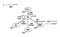
例えば、図16は、図5および図6に記載した通信処理アプリケーションによって定義される特定の制御状態に対する例示的なオートマトンモデル1600である。具体的には、図16に示す制御状態は、ソースコードプログラム500において制御状態545として定義されるいわゆる”ring”制御状態である(図5および図6を参照)。ソースコードプログラム500の第183行における”@ring”プログラムステートメントは、ソースプログラムの観点から、この特定の制御状態の明確な記述を開始する。本発明のテストおよびチェックの特徴によれば、上記のように、この制御状態から、正確なオートマトン(例えば、オートマトンモデル1600)が抽出される。オートマトンモデル1600は、”ring”制御状態1610との間の遷移と、アプリケーションの他の制御状態(すなわち、”digits_1”制御状態1620、”idle”制御状態1630、”conn”制御状態1640、および”error”制御状態1650)の間の遷移を明確に示す。また、オートマトンモデル1600は、例示的なアプリケーションにおいて発生するさまざまなイベント(すなわち、イベント1660〜イベント1695を明確に例示している。さらに、図17に示す完全なオートマトンモデル1700は、図5および図6に記載された、本発明により自動生成された完全な通信処理アプリケーションの例示的な完全なオートマトンモデルである。
【0062】
本発明の上記の実施例は、関連米国特許出願により書かれ(例えば、図5および図6を参照)、上記の本発明の原理に従ってテストされたCソースプログラムを使用している。本発明の発明者がさらに認識したところでは、ある種のユーザ(例えば、検証システムプログラマやソフトウェアテストエンジニア)は、上記の仕様フォーマットに従って駆動されるイベントを定義することによって自分のシステム設計プロセスを開始したいと考えることがある。例えば、このようなユーザは、問題となるイベント駆動システムを直接にコーディングするために上記の仕様フォーマットを使用することが考えられる。本発明のこのような実施例によれば、このような変換を容易にするためにテンプレートが用いられる。以下に、このような状態マシンコードをコンパイルおよび実行のために標準Cに変換する際に用いられる例示的なCコードテンプレートを示す。
![]()
上記のCコードテンプレートは、状態マシン仕様からCへの完全な変換のためのフレームワークを提供する。認識されるように、この例示的なCコードテンプレートは、モデルチェッカツール自体によって、または、別のマシン上で、実行されることが可能である。テンプレートは、変換実装のコアとして使用される”state”と呼ばれるルーチンに渡される引数の型定義を含む。このルーチンは、問題としているイベント駆動システムに関連するイベントが発生するときに必ず呼び出されなければならない。テンプレートコードはさらに、本発明に従って指定される遷移規則から生成される状態マシンに対するプレースホルダ”@C”を含む。状態マシンの生成に必要な実際のプログラムコードは、当業者には直ちに理解されるはずであり、ここでこれ以上説明する必要はない。各呼出し時に、”start”ルーチンが実行され、現在のイベントに関する詳細な情報を記憶するために環境によって使用されるデータ構造体からイベント型およびパラメータ値を取得する。プロセスの現在の状態は、ルーチンへの第1引数のデータ構造体から取得され、いわゆるCのswitch文がこの状態値に対して実行されて、遷移規則における正しい位置を確定する。テンプレートの略記号”@@”は、ツールによって、すべての制御状態の名前の完全なリストに展開され、生成後(すなわち、変換後)のCコードにおいて、各状態の遷移規則に対するコード断片が置かれる場所へのジャンプが対応する。本発明の実施例によれば、仕様は、直接のコンパイルおよび実行のために、ターゲットプログラミング言語(例えば、C)に変換される。
【0064】
例えば、図18は、本発明に従ってイベント駆動ソフトウェアコードを実行しテストする際に用いられる例示的なコンピュータシステム1800を示す。具体的には、コンピュータシステム1800は、ディスプレイ1820およびキーボード1830に接続された通常のパーソナルコンピュータ1810を含む。認識されるように、例えば特定のイベント駆動ソフトウェアコードの実行中にパーソナルコンピュータ1810によって生成される情報は、コンピュータシステム1800のユーザによるアクセスのために、ディスプレイ1820に表示されることが可能である。ユーザは、ディスプレイ1820を見た結果として、通常のように、キーボード1830を用いて、パーソナルコンピュータ1810と対話しパーソナルコンピュータ1810を制御する。さらに、マウス1880やその他の周知のポインティングデバイスにより、ユーザは、パーソナルコンピュータ1810にさらに入力を提供することが可能である。例示的なコンピュータシステム1800は、さらに、例えば本発明に従ってイベント駆動アプリケーションソフトウェアコードを実行しテストするプロセッサ1840を有する。例えば、このようなイベント駆動アプリケーションソフトウェアコードは、通常のディスケット1870によりパーソナルコンピュータ1810にロードされた後、内部ディスクメモリ1860に記憶される。さらに、このコードの実行およびテストは、通常のようにして、ランダムアクセスメモリ1850(RAM)のアクセスおよび使用を必要とする。こうして、コンピュータシステム1800のユーザは、本発明に従って、ソフトウェアを実行しテストして、さまざまなアプリケーション(例えば、イベント駆動システム)を提供することができる。さらに、認識されるように、コンピュータシステム1800は、通常のようにして、特定のアプリケーションプログラムの実行およびテストのために、他のコンピュータシステムやデバイスに接続されることも可能である。
【0065】
例えば、コンピュータシステム1800は、本発明に従って、ソフトウェアを実行しテストするために用いられ、図19に示すようなエラートレース1900を生成することが可能である。エラートレース1900は、プログラムコード1910(プログラムコード行番号1〜47)からなり、図5および図6に記載した通信処理アプリケーションに対して、本発明によって生成された例示的なエラートレースである。具体的には、例示的なエラートレース1900は、イベント駆動システムのもとのソースコードにおけるエラーの存在を直接に識別するシナリオをどのようにしてチェックプロセスが生成しているかを示す。さらに、エラートレース1900は、プログラムコード1910により、エラーを再現するために実行することが可能なプログラミングレベルのステートメント(例えば、Cレベルのステートメント)で、このようなエラーを識別する。例示的なエラートレース1900では、このトレースは、Cプログラムコードステートメントの直接のシーケンス(図9、プログラムコード1920を参照)で、イベント駆動システムが、実行により、処理される最初のイベントを”Crdigit”として、例示的な状態”@busy”になることを示す。Cソースプログラムコード500(特に、第223行の制御状態555)とともに、エラートレース1900から認識されるように、このイベントの発生の可能性を予期するものはプログラムコードにはない(すなわち、コーディングエラーはない)。本発明によれば、ユーザは、モデル自体の専門的な知識や、チェックプロセス自体で用いられる中間表現の大部分についての専門的な知識なしで、エラートレース1900のみをCレベルの実行ステートメントで解釈することができる。
【0066】
以上、本発明の実施例について説明したが、当業者であればさまざまな変形が可能であり、そのような変形例も本発明の技術的範囲に入る。例えば、当業者には認識されるように、ブロック図は、本発明の原理を実現する回路例の概念図を表す。同様に、認識されるように、フローチャート、流れ図、状態遷移図、擬似コード、プログラムコードなどは、コンピュータ可読な媒体において実質的に表現され、コンピュータ、マシン、あるいはプロセッサによって(そのようなコンピュータ、マシン、あるいはプロセッサが明示的に図示されているか否かにかかわらず)実行されることが可能なさまざまなプロセスを表す。
【0067】
さらに、特許請求の範囲において、指定された機能を実行する手段として表現された要素は、例えば、(a)その機能を実行する回路要素の組合せ、または、(b)その機能を実行するソフトウェアを実行するために適当な回路と組み合わせられた任意の形式の(従って、ファームウェア、オブジェクトコード、マイクロコードなどを含む)ソフトウェア、などのような、その機能を実行する任意の手段を含む。
【0068】
【発明の効果】
以上述べたごとく、本発明によれば、イベント駆動ソフトウェアを効率的にテストし、ソースコードの通常の保守、拡張および改定のプロセスの一部として、プログラムコードへの変更の妥当性を追跡することを可能にする技術が提供される。
【図面の簡単な説明】
【図1】例示的なイベント駆動システムのブロック図である。
【図2】図1の例示的なイベント駆動システムで用いられる例示的な通信呼処理アプリケーションに対する通常のCソースコードプログラムの例を示す図である。
【図3】図1の例示的なイベント駆動システムで用いられる例示的な通信呼処理アプリケーションに対する通常のCソースコードプログラムの例を示す図である。
【図4】本発明の原理によるソフトウェア開発の例示的なオペレーションの流れ図である。
【図5】図2および図3の例示的な通信呼処理アプリケーションに対する、図4のソフトウェア開発オペレーションに従って構造化され定義された、例示的なCソースコードプログラムの図である。
【図6】図2および図3の例示的な通信呼処理アプリケーションに対する、図4のソフトウェア開発オペレーションに従って構造化され定義された、例示的なCソースコードプログラムの図である。
【図7】図5および図6の例示的なCソースコードプログラムから、本発明の原理に従って導出された、翻訳済みソースコードプログラムの図である。
【図8】図5および図6の例示的なCソースコードプログラムから、本発明の原理に従って導出された、翻訳済みソースコードプログラムの図である。
【図9】本発明の原理に従ってイベント駆動ソフトウェアをテストする例示的なオペレーションの流れ図である。
【図10】図5および図6の例示的なCソースコードプログラムから導出される中間状態マシンコードの図である。
【図11】図5および図6の例示的なCソースコードプログラムによって定義されるイベント駆動システムの例示的なマップの図である。
【図12】図11の例示的なマップを適用することから導出されるモデルチェッカ入力言語の図である。
【図13】図11の例示的なマップを適用することから導出されるモデルチェッカ入力言語の図である。
【図14】図12および図13のモデルチェッカ入力言語とともに使用される例示的なライブラリ関数のセットの図である。
【図15】図5および図6に記述される通信処理アプリケーションに対する例示的な環境モデルの図である。
【図16】図5および図6の通信処理アプリケーションによって定義される特定の制御状態に対する例示的なオートマトンモデルの図である。
【図17】図5および図6に記述される完全な通信処理アプリケーションの例示的な完全なオートマトンモデルの図である。
【図18】本発明に従って指定され書かれたイベント駆動ソフトウェアコードを実行する際に用いられる例示的なコンピュータシステム1800の図である。
【図19】図5および図6に記述される通信処理アプリケーションに対して、本発明の原理に従って生成される例示的なエラートレースの図である。
【符号の説明】
100 通信ネットワーク
105 通信デバイス
110〜114 市内局
115 市外交換機
120 市外交換機
125 市外交換機
130 市外交換機
135 データリンク
140 ネットワーク制御ポイント(NCP)
150 市外網
160 アジャンクト
200 ソースコードプログラム
500 ソースコードプログラム
510〜555 制御状態
700 翻訳済みソースコードプログラム
1000 中間状態マシンコード
1100 マップ
1120 イベント定義
1130 コード定義
1200 モデルチェッカ入力言語
1400 ライブラリ関数
1500 環境モデル
1600 オートマトンモデル
1610 ”ring”制御状態
1620 ”digits_1”制御状態
1630 ”idle”制御状態
1640 ”conn”制御状態
1650 ”error”制御状態
1700 完全なオートマトンモデル
1800 コンピュータシステム
1810 パーソナルコンピュータ
1820 ディスプレイ
1830 キーボード
1840 プロセッサ
1850 ランダムアクセスメモリ
1860 内部ディスクメモリ
1870 ディスケット
1880 マウス
1900 エラートレース[0001]
BACKGROUND OF THE INVENTION
The present invention relates to testing computer software programs, and more particularly to techniques for testing event-driven application programs.
[0002]
[Prior art]
In well-known event-driven software systems (also referred to as “reactive systems” by those skilled in the art), when an event is generated and communicated to an execution process that performs a specific action based on the occurrence of the event, A function is performed. Specifically, event driven software is used to define the behavior of the system in response to events generated by other systems, machines or peripheral devices connected to the system (eg, a computer). Well known examples of event driven systems include communications applications, call processing software, data communications software, device drivers, and computer interface applications. As will be appreciated, these types of event driven systems are state oriented. That is, in each state of the system, one particular event is expected to occur from a predefined set of events, and the system is designed to respond to that event in a well-defined manner.
[0003]
In short, as is well known, the state machine converts a time series of event stimuli or input data into a time series of response or output data through some function. For example, in an event driven system, at each point in time, each machine is in a certain so-called “control state”. This state defines the events that are expected to be generated by other machines and the type of response that will be generated upon arrival of each such event. In general, a response includes the execution of finite program code, the occurrence of a new event, and the identification of a new control state for a particular machine that responds to an input event. Thus, the state machine model of an event driven system plays an important role in the development of application program code by system programmers.
[0004]
In general, event-driven application software is written in a high-level general-purpose programming language such as the well-known C or C ++ programming language or a dedicated language such as the well-known ITU system description language (SDL). When developing actual program code for such a system, it is common to describe the operation of the associated machine using a state machine. Using a high level programming language (eg, C), a software programmer writes event-driven software code for a particular application. In general, software program development begins by examining a so-called system specification that provides a logical description of the desired operation of an application. Starting with the specification, the programmer will write the code necessary to implement the operation.
[0005]
As a result of this conventional programming process, the application program does not include individual visual contexts between the various control states of the event driven system. That is, the program code is viewed as one large “flat” file with a sequence of program instructions. Furthermore, as the original specification changes during program development (eg, additional functionality is added to the system), the required program code and additional control states are generally added to the source program in a fairly arbitrary order. In order for a programmer to understand the logic flow between control states directly from the program source code, it is necessary to follow the execution thread manually (eg, following a branch instruction or goto statement) through the source. As will be appreciated, tracing (tracing) such a logic flow is a tedious and time consuming task, especially for very large source code programs. This also leads to complexity in testing the software to find so-called “bugs” and to determine whether the application program implements the desired functionality.
[0006]
Specifically, a critical step in the development of application software code for such a system is to test the code to verify the nature of the software and ensure that the operation of the system conforms to the design objectives. It is. There are several ways to test event-driven software. For example, Boris Beizer, “Black-Box Testing: Techniques for Functional Testing of Software and Systems”, a set of tests defined from a set of John Wiley and Sons, 1984, A well-known test method of deriving is described. In general, a set of test sequences is defined in a manual process by a test engineer by examining the system design. The set of test sequences is applied to the event-driven software under test, and either “pass” or “fail” is recorded as the test result. In general, this test method applies to general software testing, but it is well known to those skilled in the art that it is prone to human error and is incomplete. In particular, the number of possible executions of the event-driven software under test is very large. In contrast, the number of tests that can be run against software in real-time execution is limited by some practical constraints such as the minimum time required to run a single test out of the total number of tests. The Thus, in general, this method can only select and apply hundreds of tests. As a result, the reliability with respect to test coverage is very low.
[0007]
A second event-driven software test method known to those skilled in the art is, for example, Lee et al. , "Principles and Methods of Testing Finite State Machines-A Survey", Proceedings of the IEEE , Vol. 84, pp. 1090-1126, 1996. This test method creates an abstract state machine model for an event-driven software program. This state machine model generally ignores most of the details of the program by capturing only a high level description of the program code. A well-known test sequence generation algorithm (see, for example, Lee's paper above) can then be applied to the state machine model to derive a relatively small test set and apply it to the software under test. Similar to the test method described above, this technique relies heavily on the manual creation of an abstract model of event-driven software. This technique is therefore sensitive to errors caused by a formal relationship mismatch between the software under test and the abstract model used to derive the applicable test. In addition, changing event-driven software requires the development of new tests, which can be tedious and time consuming.
[0008]
A third widely used test method (e.g., CH West, "Protocol Validation by Random State Exploration", Proc. 6th IFIPWG 6.1 Int. Workshop on Protocol Specification, Testing, and Verification , North-Holland Publ. , Pp. 233-242, 1986) performs a random check of the complete operation of the event-driven software to determine that the software follows the desired properties. The number of items in a complete software description is so large that it is impossible to exhaustively examine the software for testing purposes. Therefore, a well-known statistical algorithm is used to extract and analyze random samples of software behavior. However, as recognized in the same way as the other test methods above, the disadvantage of this test method is that the completeness of the software to follow the high-level nature due to the large amount of extraneous items in the complete software description. It is impossible to perform an efficient comprehensive inspection of correct operation.
[0009]
[Problems to be solved by the invention]
Therefore, there is a need for a technique for solving the above problems of the prior art and improving programming development and testing of event driven software.
[0010]
[Means for Solving the Problems]
The present invention provides a technique that allows event-driven software to be efficiently tested and to track the validity of changes to program code as part of the normal maintenance, extension and revision process of the source code. To do. Specifically, according to an embodiment of the present invention, the event-driven software code is a U.S. patent application filed on the same day as the US patent application to which the present invention claims priority ("Method and Apparatus For Developing"). Event Drive Software ”, designated and written according to the principles described in“ Related US Patent Applications ”). That is, according to an embodiment of the present invention, the source code program is defined and structured in a control-sensitive and non-control-sensitive format. According to the present invention, the event-driven source code program is parsed to extract the control state defined in the source program, and the source code is converted to an intermediate state machine format. Thereafter, according to the present invention, the intermediate state machine format is converted to the automaton format for the purpose of model checking.
[0011]
Specifically, according to a preferred embodiment, the intermediate state machine format is converted to an annotated automaton model. For example, an annotated automaton model is a verification program written in the input language of a particular model checker. Importantly, according to the present invention, each statement of the source code program is mapped to an abstraction in the automaton model. This mapping is implemented using a translation map that is defined early in the verification process. This map does not need to be revised until a new type of instruction is then introduced into the source program (eg, after a revision has been made to repair a programming error). In particular, this mapping specifies a fixed translation from a particular statement to the target language of the model checker. Thus, instructions that appear in this map are systematically converted to automaton models wherever they appear in the source code.
[0012]
In addition to the above map, a so-called environmental model is defined according to the present invention. The environment model encapsulates a minimal set of assumptions that must be made regarding the particular operating environment in which the event-driven application is run. Specifically, when the model checker input language is provided to the model checker, the environmental model is applied. As a result, according to the preferred embodiment of the present invention, the verification of the nature of the event driven system is made according to the environmental model during the testing and checking of the event driven software by the verification system. Thereafter, the results of the tests and checks are output in a well-known manner to determine whether the event-driven system is in accordance with the user's desired execution nature and behavior.
[0013]
According to the present invention, the model extraction process and the application of the model checker can be performed dynamically directly from the event-driven system program code without requiring user intervention.
[0014]
DETAILED DESCRIPTION OF THE INVENTION
The present invention provides a technique for testing event-driven software. In accordance with various aspects of the present invention, event-driven system program source code is directly converted into an automaton model that is useful in verifying that the program code conforms to the desired properties defined by the user. The Specifically, according to a preferred embodiment of the present invention, event driven system program code is translated (translated) into the target language of a particular model checker. Such a translation results in a model that includes a statement regarding whether execution of the program code affects the operation of the event-driven system (eg, whether execution of the program code generates a new event). Thus, this model extraction process of the preferred embodiment of the present invention can be used as an input to a logical model checker to determine whether the event driven system is in accordance with the desired legitimacy property specified by the user. According to the present invention, the model extraction process and the application of the model checker can be performed dynamically directly from the event-driven system program code in question without the need for user intervention.
[0015]
The invention can be realized in the form of methods and apparatuses that implement such methods. The present invention can also be realized in the form of program code embodied in a tangible medium (eg, floppy disk, CD-ROM, hard drive, or any other machine-readable storage medium). In that case, when the program code is loaded into a machine (eg, a computer) and executed by the machine, the machine becomes an apparatus for implementing the present invention. The present invention also resides in, for example, program code residing in a storage medium, loaded into or executed by a machine, or transmitted through some transmission medium such as an electric wire, cable, optical fiber, or electromagnetic radiation. It can also be realized in the form. In that case, when the program code is loaded into a machine (eg, a computer) and executed by the machine, the machine becomes an apparatus for implementing the present invention. When implemented on a general-purpose processor, the program code segments combine with the processor to become a unique device that operates analogously to specific logic circuits.
[0016]
In order to provide a background to the present invention and facilitate understanding, an exemplary event driven system is outlined. Specifically, FIG. 1 is a block diagram of an exemplary communication network. This communication network includes a myriad of event-driven applications, as will be appreciated. The
[0017]
The toll exchanges 115, 120, 125 and 130 of the
[0018]
As will be appreciated, the
[0019]
As noted above, according to a preferred embodiment of the present invention, event driven software code is specified and written according to the principles described in the above-referenced related US patent applications. Accordingly, in order to facilitate a thorough understanding of the present invention, various features of the related US patent application invention will be described in some detail below.
[0020]
According to various features of the related US patent application invention, programming techniques are provided for defining, structuring and developing event-driven software. Specifically, event driven software is structured into two basic parts. These are referred to as control-sensitive code and non-control-sensitive code in related US patent applications and in this specification. According to the present invention, the control dependent code includes an identification of the control state, a generated event that must be recognized, and a response to the arrival of a specific event in a specific state. Furthermore, within the control dependent code that defines the system, the control state is uniquely identified by a single symbol throughout this program code. Non-control-dependent code is specified separately from control-dependent code and is usually sequential required to program event-driven systems, such as device driver calls, peripheral control, table updates, variable definitions, etc. For code. In accordance with the present invention, software developers can use event driven so that core control functions (ie, states, events and responses) are clearly distinguished from external matters that do not directly affect the operation of the event driven system. Software application code can be structured. Therefore, the programmer can directly determine the exact execution flow from the control state to the control state by supervising the program code itself. This is because each control state has a strong visual context. That is, according to the present invention, the program source code is structured and defined such that the control states that define the event-driven application have a direct logical (ie, causal) relationship. This relationship is immediately apparent by examining the source code itself.
[0021]
Specifically, FIGS. 2 and 3 illustrate an example of a typical C source code program 200 (program code line numbers 1-268) for an exemplary event driven application that handles outgoing calls. As will be appreciated, the
[0022]
In accordance with the present invention, software developers can use event driven so that core control functions (ie, states, events and responses) are clearly distinguished from external matters that do not directly affect the operation of the event driven system. Software application code can be structured. Therefore, the programmer can directly determine the exact execution flow from the control state to the control state by supervising the program code itself. This is because each control state has a strong visual context. That is, according to the present invention, the program source code is structured and defined such that the control states that define the event-driven application have a direct logical (ie, causal) relationship. This relationship is immediately apparent by examining the source code itself.
[0023]
In accordance with the preferred embodiment of the present invention, the well-known ANSI standard C programming language programming extensions are employed to facilitate the definition, structuring and coding of event driven software according to the present invention. Specifically, according to a preferred embodiment of the present invention, the ANSI standard C programming language extension consists of a single symbol. As this symbol, for example, the well-known ASCII symbol “@” is selected. This is used to label all control states in the control dependent part of the program code. That is, the symbol “@” is used as the first character of all labels corresponding to the control state in the program source code. That is, according to the present invention, a program statement prefixed with an “@” label identifies a control state in the program code. This control state causes the current execution of the event driven system to wait for the arrival of the next event. After arrival of the next event, the next program code is executed along with the encoding of the necessary response to that event, resulting in a transition to a new uniquely defined control state. As will be appreciated, this response and the new control state may be different for each event processed depending on operational matters such as state information, variables, device responses, etc. stored in internal tables. There is.
[0024]
FIG. 4 is a flowchart of exemplary operations for software development according to the principles of the present invention. Specifically, specifications for the event-driven system to be programmed are defined, for example, by a system engineer (block 410). As will be appreciated by those skilled in the art, such a specification provides a description of the entire application (eg, event driven system) in which the software program is written and implemented. From the system specification, control states for implementing the event-driven system under development can be identified (block 420). This identifies the generated event that must be recognized and the response to the arrival of a particular event in a particular state. Thus, according to the present invention, the definition, structuring, and coding (block 430) of the source code program is divided into two parts, control dependent code and non-control dependent code, as described above.
[0025]
According to the present invention, within the control-dependent code defining the system, the control state is uniquely identified by a single symbol throughout this program code. As described above, according to the preferred embodiment of the present invention, "@" is used as the first character of all labels corresponding to the control state in the control dependent part of the entire program source code. That is, according to the present invention, a program statement prefixed with an “@” label identifies a wait state in the program code. In this state, the current execution of the event driven system waits for the arrival of the next event. In addition, non-control dependent code is specified separately from control dependent code and is usually required to program event driven systems such as device driver calls, peripheral control, table updates, variable definitions, etc. Is for sequential code.
[0026]
In accordance with the present invention, software developers can use event driven so that core control functions (ie, states, events and responses) are clearly distinguished from external matters that do not directly affect the operation of the event driven system. Software application code can be structured. Therefore, as one practical result of applying the principles of the present invention, the programmer can directly determine the exact execution flow from the control state to the control state by supervising the program code itself. This is because each control state has a strong visual context. That is, according to the present invention, the program source code is structured and defined such that the control states that define the event-driven application have a direct logical (ie, causal) relationship. This relationship is immediately apparent by examining the source code itself. Importantly, according to the present invention, it is further possible in event-driven software testing and verification (block 440) to determine whether the software satisfies the desired properties specified by the user. There is an advantage that you can. In particular, it is the purpose of the present invention, and it is the testing of such event-driven software that is described in more detail below.
[0027]
Continuing with the description of the above related US patent application, however, according to the present invention, software developers are able to control the core control functions (ie, states, events and responses) and externals that do not directly affect the operation of the event driven system It is possible to structure the event-driven software application code so that it is clearly distinguished from the subject matter. For example, FIGS. 5 and 6 show an exemplary C source code program 500 (program
[0028]
For example, by superficially examining the
[0029]
This logical (ie, causal) relationship between the control states and the clear execution flow that are directly recognized by looking at the
[0030]
The above advantages of the related US patent application invention are very useful in computer programming technology, and are particularly useful for defining, structuring, and developing event-driven software application programming. Of course, what is important for the successful development of an application program is the effective testing and verification of the program code against a defined set of expected properties. Various features of the present invention are aimed at and are described in more detail below in testing event driven software.
[0031]
Various features of the present invention aim at the efficient testing of event-driven software and validate the future changes to program code as part of the normal maintenance, extension and revision process of the source code. Makes it possible to track. FIG. 9 is a flowchart of exemplary operations for testing event-driven software in accordance with the principles of the present invention. Specifically, according to a preferred embodiment of the present invention, event-driven software code is specified and written according to the inventive principles of the above related US patent applications. That is, according to the preferred embodiment, the source code program is defined and structured as control-dependent and non-control-dependent formats (block 910). In accordance with the present invention, the event-driven source code program is parsed to extract the control state defined in the source program and the source code is converted to an intermediate state machine format (block 920). Thereafter, according to the present invention, the intermediate state machine format is converted to the automaton format for the purpose of model checking.
[0032]
Specifically, according to the preferred embodiment, the intermediate state machine format is converted to an annotated automaton model in the input language of a particular model checker (block 940). According to a preferred embodiment, the model checker tool is a Lucent Technologies Inc. Is a well-known "SPIN" model checker developed and available from Bell Laboratories Division. More details on this can be found in G. J. et al. Holzmann, “The Model Checker SPIN”, IEEE Trans. On Software Engineering, Vol. 23, no. 5, pp. 279-295, May 1997. Significantly, according to the present invention, each statement in the source code program is mapped to an abstraction in the automaton model (block 930). This mapping (details will be described later) is realized by using a translation map defined in the initial stage of the verification process. This map does not need to be revised until a new type of instruction is then introduced into the source program (eg, after a revision has been made to repair a programming error). In particular, this mapping specifies a fixed translation from a particular statement to the target language of the model checker. Thus, instructions that appear in this map are systematically converted to automaton models wherever they appear in the source code.
[0033]
In addition to the above map, according to the invention, so-called environmental models are defined, for example, by the user. The environment model encapsulates a minimal set of assumptions that must be made regarding the particular operating environment in which the event-driven application is run. Specifically, when a model checker input language is provided to a model checker (eg, SPIN) (block 950), an environmental model is applied (block 975). As a result, according to the preferred embodiment of the present invention, the verification of the nature of the event driven system is done according to the environmental model during testing and checking of the event driven software by the model checker (block 960). Thereafter, the test and check results are output in a well-known manner by the model checker to determine whether the event-driven system is in accordance with the user's desired execution nature and behavior (block 970).
[0034]
Important for the above testing and checking of the event driven software according to the present invention is the efficient parsing of the event driven source code program to extract the control state defined in the source program, and the source code Converting to an intermediate state machine format (see, for example, FIG. 9, block 920). That is, in order to perform model checking efficiently, it must be possible to identify the control state, events and actions (ie, responses) of the event driven system. Accordingly, another feature of the present invention is to implement a formal specification that facilitates the description of event driven systems for the purpose of model checking, as will be described in detail below.
[0035]
According to this aspect of the invention, a format is defined that facilitates the specification of an event driven system. According to various embodiments of the present invention (details below), the specification can be translated into a target programming language (eg, C) for direct compilation and execution. According to yet another embodiment of the present invention, the specification is converted into a logic verification model, such as the input language of the SPIN model check tool, using the above mapping. As will be appreciated by those skilled in the art, grammar specification tools are well known. For example, yacc (yet-another-compiler-compiler) is a well-known UNIX software utility tool that assists programmers in developing C routines that parse and interpret input streams, and also facilitates compiler and interpreter development. One (see, for example, AT Schreiner, “Using C with curses, lex and yacc”, Prentice-Hall Inc., Englewood Cliffs, NJ 07632, 1990). Similar to yacc, the specification format of the present invention provides a formalism that describes the grammar of a language and automates compiler generation for that language. However, the specification format of the present invention is intended to specify the operation of the system according to the present invention.
[0036]
Specifically, according to a preferred embodiment of the present invention, an exemplary grammar definition is as follows:
[0037]
The above exemplary grammar definitions provide a framework for defining specifications for specific applications (eg, event driven systems) according to the principles of the present invention. In this exemplary grammar definition, all terms that appear between double quotes are terminal symbols (keywords, literals, tokens). The uppercase word STRING represents an alphanumeric string, and NUMBER represents a string of one or more digits. Choices are separated by a vertical bar “|” (ie, a pipe symbol), and each grammar rule ends with a semicolon.
[0039]
According to a preferred embodiment, the specification format consists of two parts: a declaration and a specification. The declaration part of the specification of the preferred embodiment specifically includes a list of symbolic names for all events that will be used in the specification. For example, the following code fragment is an exemplary declaration according to a preferred embodiment.
[0040]
In the exemplary declaration above, all words that begin with the percent “%” symbol are keywords. For example, “% c_template” defines the name of the file that contains the template for the final implementation of the code in C (ie, the preferred implementation's target implementation language). In addition, the “% p_map” statement is a file that can be used to define the relationship between the C code of the implementation and the abstract representation (ie, mapping) of the code used for validation in the model checker. Give a name. Further, the example declaration above includes a list of symbolic names (eg, “% event translator”) for all events that will be used in the specification and state names (eg, “%” for all control states in the specification). % State S_idle ").
[0042]
According to the invention, the core of the specification format is the specification of the set of transition rules for the event driven system. In this specification, the state specification is composed of a sequence of transition rules specified by the following notation.
For example, the following code fragment is an exemplary control state specification according to a preferred embodiment.
In the above exemplary control state specification, the transition rule begins with a state name (eg, “S_idle”) followed by a colon. After the colon, a series of possible transitions from this state are listed. Each transition is separated from each other by a vertical bar “|”. Each complete transition has three parts. Those three parts are the name of the event that triggers the response, the name of the new state that arrives after the response is executed (ie, the “next state”), and the response itself. The next state part of the specification defines where the control moves after the response is fully processed and includes the name of either a predefined control state or a so-called internal state. According to another embodiment of the present invention, if two events have the same next state and response, the following abbreviations can be used.
Using the above abbreviations, the events Crflash, Crdis, and Croffook all generate the same response (ie, execution of the specified code fragment and transition to state “S_idle”).
[0046]
As will be appreciated, the event driven system stops executing at each control state and waits for the arrival of the next event. In contrast, the event driven system passes through without waiting for the internal state. In addition, an “@” symbol can be prefixed to the state name in the next state segment of the transition rule to indicate that processing of the next state should continue without waiting for the arrival of the next event (note that This notation is not the same as previously described with respect to identifying control states according to various features of the invention of the related US patent application). In such cases, the last event is available if an event is needed to determine the operation of the system in the next state.
[0047]
With respect to the internal state described above, such an event encodes an internal non-event related determination of the event driven system. According to the preferred embodiment of the present invention, the syntax for internal events in the specification is the same as for control states, except that instead of event names, general Boolean conditions in the target implementation language are used. . For example, an exemplary internal state is defined as follows:
The exemplary internal state above shows that the value of a particular field (in this example, hiding two levels in a C data structure named “x”) is either state “S_otrunk” or state “S_idle_E6”. It is specified that the control is to be determined. In the previous case, the portion of the action code defined after that state will be executed. In the latter case, no code is executed.
[0049]
According to a preferred embodiment, an event or condition name of "else" indicates that a default response is made when none of the explicitly listed event names or Boolean conditions are met. For example, the above exemplary internal state code fragment can be written as:
According to this internal state code fragment, when this condition is reached, if the condition “{x->drv-> trunk}” is evaluated and “false” (false), there is no code fragment to be executed and the state Only the transition to “S_idle_E6” occurs.
[0051]
Furthermore, with respect to event-driven system specifications, it may be useful to define a common action fragment that must be executed immediately after receiving an event in a controlled state. By definition, such code fragments should be executed before any transition rules are applied. According to a preferred embodiment of the present invention, the keyword “onrecept” is used to define such a common action fragment. Here is an example of how this keyword is used:
In the example code fragment above, the state is an internal state, so it can always be referenced with the “@” prefix in the next state segment. The “onrecept” code is executed as soon as this state is reached by the transition, and the condition “(y == nil)” is evaluated. If this condition is “true” (true), the system moves to another internal state named “S_orig_E54”; if “false” (false), the system moves to the internal state “S_orig_E55” and is new. Processing continues without waiting for an event.
[0053]
Finally, for this specification, it may be useful to specify an intermediate transition state that bypasses all condition checks and goes to the next state unconditionally. According to a preferred embodiment of the present invention, a condition that is always true is represented by the keyword “always” as shown in the following example code fragment.
Implementation of the above formal specification when describing an event driven system for model checking purposes provides a specification format for describing the operation of the event driven system.
[0055]
To further illustrate the various features and advantages of the present invention in testing event-driven software, FIG. 10 illustrates source code for the exemplary C
[0056]
Specifically, by carefully examining the intermediate state machine code 1000, the event of the declaration part of the code 1000 (see, for example, the code section 1010) and the control state (see, for example, the code section 1020) are clearly known. Further, according to the present invention, various state specifications within intermediate state machine code 1000 (see, for example, state specifications 1030-1050) provide a clear interaction between such events, control states and associated actions. It is shown. As already described with respect to the operation of FIG. 9, according to the present invention, the intermediate state machine node 1000 is converted to a model checker input language to perform a test of the program code in question. This conversion is facilitated by a translation map that is defined early in the verification process. In particular, this mapping specifies a fixed translation from a particular statement to the target language of the model checker. Therefore, an instruction appearing in this map is systematically converted into an automaton model wherever the instruction appears in the original source code.
[0057]
FIG. 11 shows an exemplary map 1100 for an event driven system defined by an exemplary C
[0058]
Importantly, according to the present invention, one important advantage of using a map is the ability to accurately define the appropriate level of items to apply the check process, independent of the source. Is provided to the user. The map can include “true” or “skip” as a translation of any statement (ie, the right column of
[0059]
As described above, according to a preferred embodiment of the present invention, the verification of the nature of the event driven system follows an environmental model during testing and checking of event driven software by the verification system (see FIG. 9, block 975). The environment model formalizes individual assumptions made by the user regarding the environment in which the event driven program code is executed. For example, for the exemplary communication call processing application described above, the environmental model includes formalizations regarding subscriber behavior, hardware response, and communication network performance. Specifically, FIG. 15 is an exemplary environment model 1500 (program code line numbers 1-80) for the communication processing application described in FIGS. For example,
[0060]
According to the present invention, since the map and the environment model are defined separately, the verification infrastructure needs hardly to be updated when routine changes are made to the original source code. That is, if a new basic type of statement is not introduced into the source code, the verification process can be repeated without user intervention, and the source code can be used against a large library of intrinsic legitimacy. It is possible to check that you are still following. Furthermore, according to the present invention, an accurate automaton model representing the event-driven code to be tested is automatically generated directly from the source code and verified by a logical model checker (eg, SPIN).
[0061]
For example, FIG. 16 is an
[0062]
The above embodiment of the present invention uses a C source program written by a related US patent application (see, eg, FIGS. 5 and 6) and tested according to the above principles of the present invention. As the inventors of the present invention have further recognized, certain users (eg, verification system programmers and software test engineers) start their system design process by defining events that are driven according to the above specification format. I want to do it. For example, such a user could use the above specification format to directly code the event driven system in question. According to such an embodiment of the present invention, a template is used to facilitate such conversion. The following is an exemplary C code template used in converting such state machine code to standard C for compilation and execution.
![]()
The above C code template provides a framework for a complete translation from state machine specification to C. As will be appreciated, this exemplary C code template can be executed by the model checker tool itself or on another machine. The template includes type definitions for arguments passed to a routine called “state” that is used as the core of the transformation implementation. This routine must be called whenever an event related to the event-driven system in question occurs. The template code further includes a placeholder “@C” for the state machine generated from the transition rules specified in accordance with the present invention. The actual program code required to generate the state machine should be readily understood by those skilled in the art and need not be described further here. At each invocation, the “start” routine is executed to obtain the event type and parameter values from the data structure used by the environment to store detailed information about the current event. The current state of the process is obtained from the data structure of the first argument to the routine, and a so-called C switch statement is executed on this state value to determine the correct position in the transition rule. The template abbreviation “@@” is expanded by the tool into a complete list of all control state names, and in the generated (ie, converted) C code, code fragments for the transition rules of each state are placed. The jump to the place to be dealt with corresponds. According to an embodiment of the invention, the specification is translated into a target programming language (eg, C) for direct compilation and execution.
[0064]
For example, FIG. 18 illustrates an exemplary computer system 1800 used in executing and testing event-driven software code in accordance with the present invention. Specifically, computer system 1800 includes a regular personal computer 1810 connected to a
[0065]
For example, the computer system 1800 can be used to run and test software in accordance with the present invention to generate an
[0066]
Although the embodiments of the present invention have been described above, various modifications can be made by those skilled in the art, and such modifications also fall within the technical scope of the present invention. For example, as will be appreciated by those skilled in the art, a block diagram represents a conceptual diagram of an example circuit that implements the principles of the present invention. Similarly, as will be appreciated, flowcharts, flowcharts, state transition diagrams, pseudo code, program code, etc. are substantially represented in computer readable media and may be represented by a computer, machine, or processor (such a computer, machine (Or alternatively, whether or not a processor is explicitly illustrated) represents various processes that can be executed.
[0067]
Further, in the claims, the element expressed as the means for executing the specified function may be, for example, (a) a combination of circuit elements that execute the function, or (b) software that executes the function. Any means of performing that function is included, such as any form of software (and thus including firmware, object code, microcode, etc.) combined with appropriate circuitry to perform.
[0068]
【The invention's effect】
As described above, according to the present invention, event-driven software can be efficiently tested and the validity of changes to program code can be tracked as part of the normal maintenance, extension and revision process of the source code. Techniques that enable this are provided.
[Brief description of the drawings]
FIG. 1 is a block diagram of an exemplary event driven system.
2 illustrates an example of a typical C source code program for an exemplary communication call processing application used in the exemplary event driven system of FIG.
FIG. 3 illustrates an example of a typical C source code program for an exemplary communication call processing application used in the exemplary event driven system of FIG.
FIG. 4 is a flow diagram of exemplary operations for software development according to the principles of the present invention.
5 is a diagram of an exemplary C source code program structured and defined according to the software development operations of FIG. 4 for the exemplary communications call processing application of FIGS. 2 and 3. FIG.
6 is a diagram of an exemplary C source code program structured and defined according to the software development operations of FIG. 4 for the exemplary communications call processing application of FIGS. 2 and 3. FIG.
7 is a diagram of a translated source code program derived according to the principles of the present invention from the exemplary C source code program of FIGS. 5 and 6. FIG.
8 is a diagram of a translated source code program derived according to the principles of the present invention from the exemplary C source code program of FIGS. 5 and 6. FIG.
FIG. 9 is a flow diagram of an exemplary operation for testing event-driven software in accordance with the principles of the present invention.
10 is a diagram of intermediate state machine code derived from the exemplary C source code program of FIGS. 5 and 6. FIG.
11 is a diagram of an example map of an event driven system defined by the example C source code program of FIGS. 5 and 6. FIG.
12 is a diagram of a model checker input language derived from applying the example map of FIG.
13 is a diagram of a model checker input language derived from applying the exemplary map of FIG.
14 is a diagram of an exemplary set of library functions used with the model checker input language of FIGS. 12 and 13. FIG.
15 is an exemplary environmental model for the communication processing application described in FIGS. 5 and 6. FIG.
16 is an exemplary automaton model for a particular control state defined by the communication processing application of FIGS. 5 and 6. FIG.
17 is a diagram of an exemplary complete automaton model of the complete communication processing application described in FIGS. 5 and 6. FIG.
FIG. 18 is a diagram of an example computer system 1800 used in executing event-driven software code specified and written in accordance with the present invention.
FIG. 19 is an exemplary error trace generated in accordance with the principles of the present invention for the communication processing application described in FIGS. 5 and 6;
[Explanation of symbols]
100 communication network
105 Communication device
110-114 City Bureau
115 long distance exchange
120 long distance exchange
125 long distance exchange
130 Long distance exchange
135 Data Link
140 Network Control Point (NCP)
150 Intercity network
160 Adjunct
200 Source code program
500 source code program
510-555 Control state
700 Translated source code program
1000 Intermediate state machine code
1100 map
1120 Event definition
1130 Code definition
1200 Model Checker input language
1400 Library functions
1500 environmental model
1600 automaton model
1610 "ring" control state
1620 "digits_1" control state
1630 "idle" control state
1640 "conn" control state
1650 "error" control state
1700 Complete automaton model
1800 computer system
1810 Personal Computer
1820 display
1830 keyboard
1840 processor
1850 random access memory
1860 Internal disk memory
1870 diskette
1880 mouse
1900 error trace
Claims (26)
b.前記ソースプログラムを構文解析して複数の制御状態を識別し、該ソースプログラムを状態マシンフォーマットに変換するステップと、
c.前記ソースプログラムの複数の命令に翻訳マップを適用するステップと、
d.前記ソースプログラムの状態マシンフォーマットを検証プログラムに変換するステップと、
e.前記検証プログラムに環境モデルを適用するステップと、
f.検証ツールにおいて前記検証プログラムを用いて前記ソフトウェアをテストするステップとを有することを特徴とするソフトウェアテスト方法。a. Providing a software source program including a plurality of instructions;
b. Parsing the source program to identify a plurality of control states and converting the source program into a state machine format;
c. Applying a translation map to a plurality of instructions of the source program;
d. Converting the state machine format of the source program into a verification program;
e. Applying an environmental model to the verification program;
f. And a step of testing the software using the verification program in a verification tool.
前記第1ソースコードセグメントは、前記イベント駆動システムに関連する複数の制御状態を定義する第1命令集合と、前記イベント駆動システムの複数のイベントを定義する第2命令集合と、前記イベント駆動システムの複数のアクションを定義する第3命令集合とを含み、
前記複数の制御状態の各制御状態は、前記第1ソースコードセグメントの第1命令集合内に識別子を有し、該識別子は、識別されるすべての制御状態に共通するプログラミング記号であることを特徴とする請求項1に記載の方法。The source program includes a first source code segment that causes a computer to execute an event-driven program, and a second code segment that includes at least one instruction set that defines sequential control of the computer that executes the event-driven program. ,
The first source code segment includes a first instruction set that defines a plurality of control states associated with the event-driven system, a second instruction set that defines a plurality of events of the event-driven system, and the event-driven system A third set of instructions defining a plurality of actions,
Each control state of the plurality of control states has an identifier in a first instruction set of the first source code segment, the identifier being a programming symbol common to all identified control states. The method according to claim 1.
前記複数のマッピング命令を前記ソースプログラムの複数の命令と比較して一致する命令を検出するステップと、
前記ソースプログラムの命令に一致するマッピング命令をモデルチェッカの入力言語に変換するステップとを有することを特徴とする請求項3に記載の方法。Step c is
Comparing the plurality of mapping instructions with a plurality of instructions of the source program to detect matching instructions;
The method according to claim 3, further comprising the step of converting a mapping instruction that matches the instruction of the source program into an input language of a model checker.
前記ソースプログラムを構文解析して複数の制御状態を識別し、該ソースプログラムを状態マシンフォーマットに変換する手段と、
前記ソースプログラムの複数の命令に翻訳マップを適用する手段と、
前記ソースプログラムの状態マシンフォーマットを、モデルチェッカの入力言語によるモデルチェッカプログラムに変換する手段と、
前記モデルチェッカプログラムに環境モデルを適用する手段と、
モデルチェッカにおいて前記モデルチェッカプログラムを用いて前記ソフトウェアをテストする手段と、
前記ソフトウェアのテストの結果を表示する手段とを有することを特徴とするソフトウェアテスト装置。Means for providing a software source program including a plurality of instructions;
Means for parsing the source program to identify a plurality of control states and converting the source program into a state machine format;
Means for applying a translation map to a plurality of instructions of the source program;
Means for converting the state machine format of the source program into a model checker program in an input language of a model checker;
Means for applying an environmental model to the model checker program;
Means for testing the software using the model checker program in a model checker;
And a software test apparatus for displaying a result of the software test.
前記第1ソースコードセグメントは、前記イベント駆動システムに関連する複数の制御状態を定義する第1命令集合と、前記イベント駆動システムの複数のイベントを定義する第2命令集合と、前記イベント駆動システムの複数のアクションを定義する第3命令集合とを含み、
前記複数の制御状態の各制御状態は、前記第1ソースコードセグメントの第1命令集合内に識別子を有し、該識別子は、識別されるすべての制御状態に共通するプログラミング記号であることを特徴とする請求項8に記載の装置。The source program includes a first source code segment that causes a computer to execute an event-driven program, and a second code segment that includes at least one instruction set that defines sequential control of the computer that executes the event-driven program. ,
The first source code segment includes a first instruction set that defines a plurality of control states associated with the event-driven system, a second instruction set that defines a plurality of events of the event-driven system, and the event-driven system A third set of instructions defining a plurality of actions,
Each control state of the plurality of control states has an identifier in a first instruction set of the first source code segment, the identifier being a programming symbol common to all identified control states. The apparatus according to claim 8.
前記複数のマッピング命令を前記ソースプログラムの複数の命令と比較して一致する命令を検出する手段と、
前記ソースプログラムの命令に一致するマッピング命令をモデルチェッカの入力言語に変換する手段とを有することを特徴とする請求項10に記載の装置。The means for applying the translation map is:
Means for comparing the plurality of mapping instructions with a plurality of instructions of the source program to detect matching instructions;
11. The apparatus according to claim 10, further comprising means for converting a mapping instruction that matches an instruction of the source program into an input language of a model checker.
前記複数の命令は、機械によって実行されるときに該機械がイベント駆動ソフトウェアをテストする方法を実行する命令を含み、
前記方法は、
ソフトウェアのソースプログラムを構文解析して複数の制御状態を識別し、該ソースプログラムを状態マシンフォーマットに変換するステップと、
前記ソースプログラムに翻訳マップを適用するステップと、
前記ソースプログラムの状態マシンフォーマットを検証プログラムに変換するステップと、
前記検証プログラムに環境モデルを適用するステップと、
前記検証プログラムを検証システムに入力することによって前記ソフトウェアをテストするステップとによりイベント駆動ソフトウェアをテストすることを特徴とする機械可読媒体。In a machine readable medium storing a plurality of instructions,
The plurality of instructions includes instructions for executing a method by which the machine tests event-driven software when executed by the machine;
The method
Parsing a software source program to identify a plurality of control states and converting the source program to a state machine format;
Applying a translation map to the source program;
Converting the state machine format of the source program into a verification program;
Applying an environmental model to the verification program;
A machine readable medium for testing event driven software by testing the software by inputting the verification program into a verification system.
前記第1ソースコードセグメントは、前記イベント駆動システムに関連する複数の制御状態を定義する第1命令集合と、前記イベント駆動システムの複数のイベントを定義する第2命令集合と、前記イベント駆動システムの複数のアクションを定義する第3命令集合とを含み、
前記複数の制御状態の各制御状態は、前記第1ソースコードセグメントの第1命令集合内に識別子を有し、該識別子は、識別されるすべての制御状態に共通するプログラミング記号であることを特徴とする請求項13に記載の機械可読媒体。The source program includes a first source code segment that causes a computer to execute an event-driven program, and a second code segment that includes at least one instruction set that defines sequential control of the computer that executes the event-driven program. ,
The first source code segment includes a first instruction set that defines a plurality of control states associated with the event-driven system, a second instruction set that defines a plurality of events of the event-driven system, and the event-driven system A third set of instructions defining a plurality of actions,
Each control state of the plurality of control states has an identifier in a first instruction set of the first source code segment, the identifier being a programming symbol common to all identified control states. The machine-readable medium according to claim 13.
前記メモリ内のプログラミング言語ステートメントの列を受け取る手段とを有するソフトウェアテストシステムにおいて、
前記プログラミング言語ステートメントの列は、前記コンピュータにイベント駆動システムを実行させる第1ソースコードセグメントおよび第2ソースコードセグメントを含み、
前記第1ソースコードセグメントは、前記イベント駆動システムの複数の制御状態を定義する第1命令集合と、前記イベント駆動システムの複数のイベントを定義する第2命令集合と、前記イベント駆動システムの複数のアクションを定義する第3命令集合とを含み、
前記複数の制御状態の各制御状態は、前記第1ソースコードセグメントの第1命令集合内に識別子を有し、該識別子は、識別されるすべての制御状態に共通するプログラミング記号であり、
前記第2ソースコードセグメントは、前記イベント駆動プログラムを実行する際のコンピュータの順次的な制御を定義する少なくとも1つの命令集合を含み、
前記ソフトウェアテストシステムはさらに、
前記第1ソースコードセグメントを構文解析して前記複数の制御状態を識別し、前記第1ソースコードセグメントおよび前記第2ソースコードセグメントを状態マシンフォーマットに変換する手段と、
前記第1ソースコードセグメントおよび前記第2ソースコードセグメントに翻訳マップを適用する手段と、
前記状態マシンフォーマットを、モデルチェッカの入力言語によるモデルチェッカプログラムに変換する手段と、
前記モデルチェッカプログラムに環境モデルを適用する手段と、
モデルチェッカにおいて前記モデルチェッカプログラムを用いて前記ソフトウェアをテストする手段と、
前記ソフトウェアのテストの結果を表示する手段とを有することを特徴とするソフトウェアテストシステム。A computer having at least one memory;
Means for receiving a sequence of programming language statements in said memory;
The sequence of programming language statements includes a first source code segment and a second source code segment that cause the computer to execute an event driven system;
The first source code segment includes a first instruction set that defines a plurality of control states of the event-driven system, a second instruction set that defines a plurality of events of the event-driven system, and a plurality of events of the event-driven system A third set of instructions defining an action,
Each control state of the plurality of control states has an identifier in a first instruction set of the first source code segment, the identifier being a programming symbol common to all identified control states;
The second source code segment includes at least one instruction set that defines sequential control of a computer when executing the event-driven program;
The software test system further includes:
Means for parsing the first source code segment to identify the plurality of control states and converting the first source code segment and the second source code segment into a state machine format;
Means for applying a translation map to the first source code segment and the second source code segment;
Means for converting the state machine format into a model checker program in a model checker input language;
Means for applying an environmental model to the model checker program;
Means for testing the software using the model checker program in a model checker;
And a software test system for displaying a result of the software test.
前記コンピュータで前記オブジェクトプログラムを実行して前記イベント駆動システムを実現する手段とをさらに有することを特徴とする請求項18に記載のソフトウェアテストシステム。Means for compiling the first source code segment and the second source code segment into an object program in the memory;
The software test system according to claim 18, further comprising means for executing the object program on the computer to realize the event driving system.
Applications Claiming Priority (2)
| Application Number | Priority Date | Filing Date | Title |
|---|---|---|---|
| US09/211,967 US6353896B1 (en) | 1998-12-15 | 1998-12-15 | Method and apparatus for testing event driven software |
| US09/211967 | 1998-12-15 |
Publications (2)
| Publication Number | Publication Date |
|---|---|
| JP2000181750A JP2000181750A (en) | 2000-06-30 |
| JP3631647B2 true JP3631647B2 (en) | 2005-03-23 |
Family
ID=22788997
Family Applications (1)
| Application Number | Title | Priority Date | Filing Date |
|---|---|---|---|
| JP35361399A Expired - Fee Related JP3631647B2 (en) | 1998-12-15 | 1999-12-13 | Software test method |
Country Status (5)
| Country | Link |
|---|---|
| US (1) | US6353896B1 (en) |
| EP (1) | EP1014265B1 (en) |
| JP (1) | JP3631647B2 (en) |
| CA (1) | CA2288378A1 (en) |
| DE (1) | DE69900810T2 (en) |
Families Citing this family (50)
| Publication number | Priority date | Publication date | Assignee | Title |
|---|---|---|---|---|
| DE59902955D1 (en) * | 1998-06-26 | 2002-11-07 | Deutsche Telekom Ag | METHOD FOR TESTING JAVA BYTECODE PROGRAMS FOR SECURITY PROPERTIES |
| US6981215B1 (en) | 1998-12-31 | 2005-12-27 | Microsoft Corp. | System for converting event-driven code into serially executed code |
| US6889379B1 (en) * | 1998-12-31 | 2005-05-03 | Microsoft Corporation | Transporting objects between a client and a server |
| AU763141B2 (en) * | 1999-04-19 | 2003-07-17 | Motorola Australia Pty Ltd | A method of detecting illegal sequences of code execution |
| US6691078B1 (en) * | 1999-07-29 | 2004-02-10 | International Business Machines Corporation | Target design model behavior explorer |
| US6499136B1 (en) * | 1999-11-10 | 2002-12-24 | Lucent Technologies Inc. | Single-shot entry code for software state transition |
| US20010037492A1 (en) * | 2000-03-16 | 2001-11-01 | Holzmann Gerard J. | Method and apparatus for automatically extracting verification models |
| SE522408C2 (en) | 2000-04-27 | 2004-02-10 | Microsoft Corp | Computer program and procedure for automated testing of a computer's functionality |
| US20020100022A1 (en) * | 2000-05-08 | 2002-07-25 | Holzmann Gerard J. | Method and apparatus for automatic verification of properties of a concurrent software system |
| US7213230B2 (en) * | 2000-12-28 | 2007-05-01 | Yeda Research And Development Co. Ltd. | Playing scenarios of system behavior |
| SE518751C2 (en) | 2001-01-03 | 2002-11-19 | Microsoft Corp | Method and system where an external server receives information on individual mobile terminals' radio transmission capacity |
| US7117484B2 (en) * | 2002-04-16 | 2006-10-03 | International Business Machines Corporation | Recursive use of model based test generation for middleware validation |
| US20040013250A1 (en) * | 2002-07-22 | 2004-01-22 | Sreekrishna Kotnur | System and method of tracking component object requests |
| US7334219B2 (en) * | 2002-09-30 | 2008-02-19 | Ensco, Inc. | Method and system for object level software testing |
| US7493603B2 (en) * | 2002-10-15 | 2009-02-17 | International Business Machines Corporation | Annotated automaton encoding of XML schema for high performance schema validation |
| US7543274B2 (en) | 2003-12-22 | 2009-06-02 | The United States Of America As Represented By The Administrator Of The National Aeronautics And Space Administration | System and method for deriving a process-based specification |
| US20050177578A1 (en) * | 2004-02-10 | 2005-08-11 | Chen Yao-Ching S. | Efficient type annontation of XML schema-validated XML documents without schema validation |
| US7437374B2 (en) * | 2004-02-10 | 2008-10-14 | International Business Machines Corporation | Efficient XML schema validation of XML fragments using annotated automaton encoding |
| US7412699B2 (en) * | 2004-04-14 | 2008-08-12 | International Business Machines Corporation | Using behavioral annotations in source code to build middleware applications |
| US20060020413A1 (en) * | 2004-07-26 | 2006-01-26 | Septon Daven W | Methods and apparatus for providing automated test equipment with a means to jump and return in a test program |
| US20060020920A1 (en) * | 2004-07-26 | 2006-01-26 | Daven Walt Septon | Methods and apparatus for providing automated test equipment with a means to jump between tests in a test program |
| US7703082B2 (en) * | 2004-12-07 | 2010-04-20 | International Business Machines Corporation | Controlling user intervention in a multi-processing computer system |
| US7861239B2 (en) * | 2005-05-23 | 2010-12-28 | International Business Machines Corporation | Data migration between versions of software |
| US7647219B2 (en) * | 2005-07-11 | 2010-01-12 | Texas Instruments Incorporated | Event-driven test framework |
| JP2007079954A (en) | 2005-09-14 | 2007-03-29 | Sony Corp | Information processing method and device, recording medium and program |
| US20070101196A1 (en) * | 2005-11-01 | 2007-05-03 | Rogers William A | Functional testing and verification of software application |
| US20070245327A1 (en) * | 2006-04-17 | 2007-10-18 | Honeywell International Inc. | Method and System for Producing Process Flow Models from Source Code |
| US7631227B2 (en) * | 2006-11-21 | 2009-12-08 | Etaliq Inc. | Automated testing and control of networked devices |
| US7917900B2 (en) | 2007-03-30 | 2011-03-29 | Microsoft Corporation | Enabling analysis of software source code |
| US8161496B2 (en) * | 2007-07-31 | 2012-04-17 | Microsoft Corporation | Positive and negative event-based testing |
| US9026394B2 (en) * | 2007-10-08 | 2015-05-05 | Wurldtech Security Technologies | Testing and mitigation framework for networked devices |
| WO2010060082A2 (en) * | 2008-11-24 | 2010-05-27 | Tekelec | Systems. methods, and computer readable media for providing toll-free service in a telecommunications network |
| US9712341B2 (en) | 2009-01-16 | 2017-07-18 | Tekelec, Inc. | Methods, systems, and computer readable media for providing E.164 number mapping (ENUM) translation at a bearer independent call control (BICC) and/or session intiation protocol (SIP) router |
| US8453117B2 (en) * | 2010-03-09 | 2013-05-28 | Fujitsu Limited | Providing software validation as a service |
| US8683451B1 (en) | 2010-04-30 | 2014-03-25 | The United States Of America As Represented By The Secretary Of The Navy | System and method for translating software code |
| JP2012059026A (en) * | 2010-09-09 | 2012-03-22 | Hitachi Ltd | Source code conversion method and source code conversion program |
| US9027002B2 (en) | 2010-10-27 | 2015-05-05 | Hitachi, Ltd. | Method of converting source code and source code conversion program |
| US9043746B2 (en) | 2011-03-07 | 2015-05-26 | International Business Machines Corporation | Conducting verification in event processing applications using formal methods |
| US8990770B2 (en) | 2011-05-25 | 2015-03-24 | Honeywell International Inc. | Systems and methods to configure condition based health maintenance systems |
| JP5643971B2 (en) * | 2011-12-01 | 2014-12-24 | 株式会社日立製作所 | Source code conversion method and source code conversion program |
| CN104204975B (en) * | 2012-03-26 | 2016-10-12 | 三菱电机株式会社 | Sequencer debugging auxiliary device |
| US8832649B2 (en) | 2012-05-22 | 2014-09-09 | Honeywell International Inc. | Systems and methods for augmenting the functionality of a monitoring node without recompiling |
| US8832716B2 (en) * | 2012-08-10 | 2014-09-09 | Honeywell International Inc. | Systems and methods for limiting user customization of task workflow in a condition based health maintenance system |
| US9037920B2 (en) | 2012-09-28 | 2015-05-19 | Honeywell International Inc. | Method for performing condition based data acquisition in a hierarchically distributed condition based maintenance system |
| US20140282414A1 (en) * | 2013-03-14 | 2014-09-18 | Cadence Design Systems, Inc. | Method and system for debugging of a program |
| DE112014002979T8 (en) * | 2014-05-08 | 2016-06-09 | Mitsubishi Electric Corporation | Development tool, program modification device and program modification system |
| US9892027B2 (en) * | 2014-07-09 | 2018-02-13 | Fujitsu Limited | Event-driven software testing |
| US9646257B2 (en) * | 2014-09-03 | 2017-05-09 | Microsoft Technology Licensing, Llc | Probabilistic assertions and verifying them |
| KR102180592B1 (en) * | 2018-12-14 | 2020-11-18 | 주식회사 엘지씨엔에스 | Method and system for testing it system |
| CN113010158B (en) * | 2021-03-18 | 2022-09-06 | 中国科学技术大学 | Pure state trigger action programming paradigm to event driven system transition method |
Family Cites Families (4)
| Publication number | Priority date | Publication date | Assignee | Title |
|---|---|---|---|---|
| US5522073A (en) * | 1993-11-22 | 1996-05-28 | Hewlett-Packard Company | Method and apparatus for automating and controlling execution of software tools and tool sets via when/then relationships |
| CA2147536A1 (en) * | 1994-06-01 | 1995-12-02 | Gerard Johan Holzmann | On-the-fly model checking with partial-order state space reduction |
| JP2692609B2 (en) * | 1994-09-26 | 1997-12-17 | 日本電気株式会社 | Multitask program debugging method and apparatus |
| US6158031A (en) * | 1998-09-08 | 2000-12-05 | Lucent Technologies, Inc. | Automated code generating translator for testing telecommunication system devices and method |
-
1998
- 1998-12-15 US US09/211,967 patent/US6353896B1/en not_active Expired - Lifetime
-
1999
- 1999-11-02 CA CA002288378A patent/CA2288378A1/en not_active Abandoned
- 1999-12-07 EP EP99309818A patent/EP1014265B1/en not_active Expired - Lifetime
- 1999-12-07 DE DE69900810T patent/DE69900810T2/en not_active Expired - Lifetime
- 1999-12-13 JP JP35361399A patent/JP3631647B2/en not_active Expired - Fee Related
Also Published As
| Publication number | Publication date |
|---|---|
| EP1014265B1 (en) | 2002-01-23 |
| US6353896B1 (en) | 2002-03-05 |
| DE69900810D1 (en) | 2002-03-14 |
| DE69900810T2 (en) | 2002-08-29 |
| EP1014265A1 (en) | 2000-06-28 |
| CA2288378A1 (en) | 2000-06-15 |
| JP2000181750A (en) | 2000-06-30 |
Similar Documents
| Publication | Publication Date | Title |
|---|---|---|
| JP3631647B2 (en) | Software test method | |
| Felty et al. | Feature specification and automated conflict detection | |
| US6148277A (en) | Apparatus and method for generating model reference tests | |
| Holzmann et al. | Automating software feature verification | |
| US6385765B1 (en) | Specification and verification for concurrent systems with graphical and textual editors | |
| CA2118437C (en) | Application-oriented telecommunication system interface | |
| US20040205720A1 (en) | Augmenting debuggers | |
| Paakki et al. | Software metrics by architectural pattern mining | |
| CN110837466B (en) | Embedded software dynamic test method based on source code piling | |
| CN101980546B (en) | Intelligent network platform, service execution method and method for analyzing service abnormality | |
| JP2000232516A (en) | Method, creation module, server, control module, and storage means for creating validation rules | |
| Chung et al. | Testing of concurrent programs based on message sequence charts | |
| KR20030015200A (en) | Robust logging system for embedded systems for software compilers | |
| Tsai et al. | Scenario-based test case generation for state-based embedded systems | |
| US6313768B1 (en) | System and method for trace diagnostics of telecommunications systems | |
| CN118312250A (en) | Java static code analysis-based call link generation method | |
| Probert et al. | Rapid generation of functional tests using MSCs, SDL and TTCN | |
| US20060198501A1 (en) | Method and device for constructing a voice dialog | |
| Lee et al. | A New Integrated Software Development Environment Based on SDL, MSC, and CHILL for Large‐scale Switching Systems | |
| EP1018684A2 (en) | Method and apparatus for developing event driven software | |
| Cheung | Petri nets for protocol engineering | |
| Chung et al. | Testing of concurrent programs after specification changes | |
| Dietrich et al. | Formal methods for communication services: meeting the industry expectations | |
| Li et al. | A tool suite for diagnosis and testing of software design specifications | |
| CN118643125B (en) | Query method and system for statically analyzing change influence surface in spring framework |
Legal Events
| Date | Code | Title | Description |
|---|---|---|---|
| A977 | Report on retrieval |
Free format text: JAPANESE INTERMEDIATE CODE: A971007 Effective date: 20041029 |
|
| TRDD | Decision of grant or rejection written | ||
| A01 | Written decision to grant a patent or to grant a registration (utility model) |
Free format text: JAPANESE INTERMEDIATE CODE: A01 Effective date: 20041122 |
|
| A61 | First payment of annual fees (during grant procedure) |
Free format text: JAPANESE INTERMEDIATE CODE: A61 Effective date: 20041217 |
|
| R150 | Certificate of patent or registration of utility model |
Free format text: JAPANESE INTERMEDIATE CODE: R150 |
|
| FPAY | Renewal fee payment (event date is renewal date of database) |
Free format text: PAYMENT UNTIL: 20071224 Year of fee payment: 3 |
|
| FPAY | Renewal fee payment (event date is renewal date of database) |
Free format text: PAYMENT UNTIL: 20081224 Year of fee payment: 4 |
|
| FPAY | Renewal fee payment (event date is renewal date of database) |
Free format text: PAYMENT UNTIL: 20081224 Year of fee payment: 4 |
|
| FPAY | Renewal fee payment (event date is renewal date of database) |
Free format text: PAYMENT UNTIL: 20091224 Year of fee payment: 5 |
|
| FPAY | Renewal fee payment (event date is renewal date of database) |
Free format text: PAYMENT UNTIL: 20101224 Year of fee payment: 6 |
|
| FPAY | Renewal fee payment (event date is renewal date of database) |
Free format text: PAYMENT UNTIL: 20101224 Year of fee payment: 6 |
|
| FPAY | Renewal fee payment (event date is renewal date of database) |
Free format text: PAYMENT UNTIL: 20111224 Year of fee payment: 7 |
|
| FPAY | Renewal fee payment (event date is renewal date of database) |
Free format text: PAYMENT UNTIL: 20111224 Year of fee payment: 7 |
|
| FPAY | Renewal fee payment (event date is renewal date of database) |
Free format text: PAYMENT UNTIL: 20121224 Year of fee payment: 8 |
|
| FPAY | Renewal fee payment (event date is renewal date of database) |
Free format text: PAYMENT UNTIL: 20131224 Year of fee payment: 9 |
|
| R250 | Receipt of annual fees |
Free format text: JAPANESE INTERMEDIATE CODE: R250 |
|
| R250 | Receipt of annual fees |
Free format text: JAPANESE INTERMEDIATE CODE: R250 |
|
| R250 | Receipt of annual fees |
Free format text: JAPANESE INTERMEDIATE CODE: R250 |
|
| LAPS | Cancellation because of no payment of annual fees |