JP3629953B2 - Exhaust gas purification device for internal combustion engine - Google Patents
Exhaust gas purification device for internal combustion engine Download PDFInfo
- Publication number
- JP3629953B2 JP3629953B2 JP16957198A JP16957198A JP3629953B2 JP 3629953 B2 JP3629953 B2 JP 3629953B2 JP 16957198 A JP16957198 A JP 16957198A JP 16957198 A JP16957198 A JP 16957198A JP 3629953 B2 JP3629953 B2 JP 3629953B2
- Authority
- JP
- Japan
- Prior art keywords
- internal combustion
- combustion engine
- exhaust
- valve
- adsorbent
- Prior art date
- Legal status (The legal status is an assumption and is not a legal conclusion. Google has not performed a legal analysis and makes no representation as to the accuracy of the status listed.)
- Expired - Fee Related
Links
Images


Classifications
-
- F—MECHANICAL ENGINEERING; LIGHTING; HEATING; WEAPONS; BLASTING
- F01—MACHINES OR ENGINES IN GENERAL; ENGINE PLANTS IN GENERAL; STEAM ENGINES
- F01N—GAS-FLOW SILENCERS OR EXHAUST APPARATUS FOR MACHINES OR ENGINES IN GENERAL; GAS-FLOW SILENCERS OR EXHAUST APPARATUS FOR INTERNAL COMBUSTION ENGINES
- F01N3/00—Exhaust or silencing apparatus having means for purifying, rendering innocuous, or otherwise treating exhaust
- F01N3/08—Exhaust or silencing apparatus having means for purifying, rendering innocuous, or otherwise treating exhaust for rendering innocuous
- F01N3/0807—Exhaust or silencing apparatus having means for purifying, rendering innocuous, or otherwise treating exhaust for rendering innocuous by using absorbents or adsorbents
- F01N3/0828—Exhaust or silencing apparatus having means for purifying, rendering innocuous, or otherwise treating exhaust for rendering innocuous by using absorbents or adsorbents characterised by the absorbed or adsorbed substances
- F01N3/0835—Hydrocarbons
-
- Y—GENERAL TAGGING OF NEW TECHNOLOGICAL DEVELOPMENTS; GENERAL TAGGING OF CROSS-SECTIONAL TECHNOLOGIES SPANNING OVER SEVERAL SECTIONS OF THE IPC; TECHNICAL SUBJECTS COVERED BY FORMER USPC CROSS-REFERENCE ART COLLECTIONS [XRACs] AND DIGESTS
- Y02—TECHNOLOGIES OR APPLICATIONS FOR MITIGATION OR ADAPTATION AGAINST CLIMATE CHANGE
- Y02T—CLIMATE CHANGE MITIGATION TECHNOLOGIES RELATED TO TRANSPORTATION
- Y02T10/00—Road transport of goods or passengers
- Y02T10/10—Internal combustion engine [ICE] based vehicles
- Y02T10/12—Improving ICE efficiencies
Landscapes
- Engineering & Computer Science (AREA)
- Chemical & Material Sciences (AREA)
- Combustion & Propulsion (AREA)
- Mechanical Engineering (AREA)
- General Engineering & Computer Science (AREA)
- Exhaust Gas After Treatment (AREA)
- Output Control And Ontrol Of Special Type Engine (AREA)
- Electrical Control Of Air Or Fuel Supplied To Internal-Combustion Engine (AREA)
- Combined Controls Of Internal Combustion Engines (AREA)
- Exhaust Gas Treatment By Means Of Catalyst (AREA)
Description
【0001】
【発明の属する技術分野】
この発明は、内燃機関の排気浄化装置、特に排気通路に介装したHC吸着剤によって始動直後のHCの排出を防止するようにした排気浄化装置に関する。
【0002】
【従来の技術】
自動車の内燃機関から排出される排気ガスの浄化には、貴金属(白金、パラジウム、ロジウム等)またはその他の金属を担持した三元触媒が従来から使われている。このような触媒は、排気ガス中の有害成分であるHC、CO、NOx等を酸化もしくは還元して浄化しているが、この触媒作用を得るためには、排気温度が高くなければならず、例えばHCの触媒による浄化のためには、一般に、200〜300℃程度の温度が必要である。しかし内燃機関の始動直後では、排気ガス温度が低く、上記の触媒が活性する温度(例えば200℃以上)に達しないため、HCの浄化はほとんど行われず、内燃機関で発生したHCの多くが大気へ放出されてしまう。
【0003】
そこで、内燃機関の排気系に、一般的な三元触媒装置に加えて、低温条件でHCを吸着するHC吸着剤を配置し、触媒活性前に排出されるHCを吸着するようにしたものが公知である(特開平6−241028号公報、特開平7−144119号公報等)。このHC吸着剤は、例えばゼオライト等を用いたものであり、低温時には、HCを吸着し、その後、所定の脱離温度に達すると、吸着していたHCが脱離する特性を有している。この脱離したHCは、活性した触媒によって浄化処理されることになる。
【0004】
なお、特開平7−109934号公報には、冷間始動時に吸排気弁の開閉時期を変化させることにより、内燃機関から発生するHCの量そのものを減少させるようにした技術が開示されており、また特開平8−158897号公報には、冷間始動時に排気シャッタバルブを閉じることにより排圧を上昇させて未燃成分の排出を抑制するとともに、排出シャッタバルブの上流側にHC吸着剤を配置した構成が開示されている。
【0005】
【発明が解決しようとする課題】
しかしながら、上記のHC吸着剤、特にゼオライト系の吸着剤にあっては、分子量の大きなHCに対しては吸着効率が高いものの、分子量の小さなHCに対しては吸着効率が低く、従って、触媒活性前の段階では、この分子量の小さなHCが大気へ放出され易い、という問題がある。
【0006】
【課題を解決するための手段】
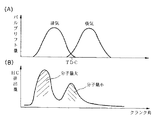
図1は、一般的な吸排気弁の開閉時期と排気弁下流位置におけるHC排出量との関係を示した特性図であり、この図に示すように、HCの排出は、排気弁が開き始めたときと、ピストンが上死点に達する付近との2つのピークを有している。ここで、それぞれのHCの分子量に着目すると、第1のピークの分子量は大きく、第2のピークの分子量は小さい。この後者のHCは、クレビスボリュームに残留していた液状の燃料が気化したばかりのものと考えられ、それ故、分子量は、前者に比べて小さなものとなり、HC吸着剤での吸着効率は低い。
【0007】
そこで、請求項1に係る第1の発明では、この分子量の小さなHCの発生を、吸気弁の開時期を進角させることにより抑制し、また分子量の大きな前者のHCはHC吸着剤により確実に吸着するようにして、HCの大気への放出を大幅に減少させるようにした。
【0008】
すなわち、請求項1の内燃機関の排気浄化装置は、内燃機関の排気通路に介装され、排気中のHC(炭化水素成分)を吸着するHC吸着剤と、
内燃機関の少なくとも吸気弁側に設けられ、該吸気弁の少なくとも開時期を可変制御可能な可変動弁機構と、
内燃機関の冷間状態を検出する手段と、
この内燃機関の冷間時に、上記吸気弁の開時期を進角させる開閉時期制御手段と、
を備えている。
【0009】
上記のように吸気弁の開時期を進角させると、吸気系への排気の吹き返しが増大し、ピストン上死点付近で発生する分子量の小さなHCの排気系への排出が減少する。また、仮に排気弁側の開閉時期が固定であるとすると、このように吸気弁の開時期の進角によりバルブオーバラップが拡大し、極端な場合には、燃焼の不安定化が生じ、HC生成量自体は却って増加する可能性があるが、この燃焼の不安定化に伴って増加するHCは、その分子量が比較的大きなものであるので、HC吸着剤によって確実に吸着処理することができる。
【0010】
また、請求項3および請求項4に係る第2の発明では、上死点付近における分子量の小さなHCの発生を、排気弁の閉時期を進角させることにより抑制するようにした。
【0011】
すなわち、請求項3,4の内燃機関の排気浄化装置は、内燃機関の排気通路に介装され、排気中のHC(炭化水素成分)を吸着するHC吸着剤と、
内燃機関の少なくとも排気弁側に設けられ、該排気弁の少なくとも閉時期を可変制御可能な可変動弁機構と、
内燃機関の冷間状態を検出する手段と、
この内燃機関の冷間時に、上記排気弁の閉時期を上死点前まで進角させる開閉時期制御手段と、
を備えている。
【0012】
このように排気弁を上死点前に閉じるようにすれば、上死点付近における分子量の小さなHCの排出が抑制される。従って、HC吸着剤による分子量の比較的大きなHCに対する吸着作用と併せて、HCの排出を確実に防止できる。
【0013】
なお、上述した特開平7−109934号公報や特開平8−158897号公報の装置は、HCの分子量の大小に無関係に、内燃機関から発生するHCの総量を減少させるようにしたものであり、分子量の比較的大きなHCに対しては優れた吸着作用を有するHC吸着剤の特徴を十分に活かすことができない。
【0014】
上記HC吸着剤は、例えば請求項5のように、ゼオライト系吸着剤からなる。このゼオライト系吸着剤は、上述したように、分子量の大きなHCに対しては吸着効率が高く、分子量の小さなHCに対する吸着効率は低い。
【0015】
また、上記の冷間状態検出手段は、請求項1および請求項3のように、上記HC吸着剤が脱離開始温度以下であることを検出するものである。つまり、HC吸着剤による吸着作用が得られるときにのみ開閉時期を変化させることにより、不必要な燃焼の悪化等を最小限にすることができる。
【0016】
また、請求項2および請求項4の発明では、内燃機関の負荷が低いほど上記吸気弁開時期もしくは排気弁閉時期の進角量を小さくするようになっている。これにより、アイドルのような低負荷域での燃焼の不安定化が抑制される。
【0017】
【発明の効果】
この発明に係る内燃機関の排気浄化装置によれば、機関の冷間時に、分子量の大きなHCはHC吸着剤によって吸着し、かつ吸着されにくい分子量の小さなHCは、吸気弁開時期もしくは排気弁閉時期の進角により排出を抑制するようにしたので、全体として、HCの排出量を非常に低いレベルに低減することができる。
【0018】
特に、HC吸着剤と吸排気弁開閉時期の可変制御とを組み合わせたことにより、HC吸着剤の吸着効率を最大限に利用でき、比較的小容量のHC吸着剤でもって大幅なHCの低減を実現できるとともに、開閉時期を進角させたことに伴う燃焼の悪化等によるHCの増加分の悪影響がなく、実際に排出されるHCを大幅に低減できる。
【0019】
【発明の実施の形態】
以下、この発明の好ましい実施の形態を図面に基づいて詳細に説明する。
【0020】
図2は、この発明の第1実施例を示す構成説明図であって、内燃機関1の各シリンダ2には、燃焼室4を画成するピストン3が摺動可能に嵌合しており、かつ中央に点火プラグ5が配置されている。上記燃焼室4に排気弁6を介して接続された排気通路7には、プリ触媒コンバータとなる三元触媒装置8が介装されているとともに、その下流側に、低温時に排気中のHCを吸着する吸着剤として吸着触媒装置9が介装されている。なお、この実施例では、三元触媒装置8と吸着触媒装置9とは、同一のケーシング内に収容されている。上記吸着触媒装置9は、ゼオライト系のHC吸着成分と貴金属等の三元触媒成分とを混合した吸着触媒をセラミックス等からなる担体に担持させたものであり、吸着したHCの一部を触媒作用で酸化させるという自己浄化機能を有している。あるいは、吸着成分と触媒成分とを積層した構成とすることもできる。また、図示していないが、吸着触媒装置9のさらに下流側には、メイン触媒コンバータとなる三元触媒装置が設けられている。
【0021】
上記燃焼室4に吸気弁10を介して接続された吸気通路11には、燃料噴射弁12が吸気弁10へ向けて配置されており、さらにコレクタ13の上流側に、スロットル弁14およびエアフロメータ15が順次介装されている。
【0022】
また、内燃機関1の冷却水温を検出する水温センサ16およびクランク軸の回転角を検出するクランク角センサ17を備えており、これらのセンサ類の検出信号は、それぞれエンジンコントロールユニット18に入力されている。エンジンコントロールユニット18は、これらの検出信号に基づき、燃料噴射弁12による燃料噴射量ならびに噴射時期、点火プラグ5の点火時期等を総合的に制御している。
【0023】
また上記排気弁6および吸気弁10は、それぞれカムシャフトを主体とした動弁機構によって開閉駆動されるようになっているが、特に、吸気弁10側には、エンジンコントロールユニット18からの制御信号によってバルブリフト特性を可変制御可能な可変動弁機構19が設けられている。この実施例では、上記可変動弁機構19として、例えば、クランク軸とカムシャフトとの位相をずらすことにより、バルブ作動角を変化させずにバルブ開時期および閉時期を同時に一定量進角させ得る公知の構成のものが用いられている。なお、特開平6−185321号公報等に開示されているようなバルブ作動角をも併せて可変制御し得る形式のものを用いることもできる。
【0024】
図3は、上記実施例におけるバルブ開閉時期と排気弁6下流でのHC排出量とを示した特性図である。上記実施例では、内燃機関1の暖機が完了している状態では、ピストン上死点位置(TDC)を挟んで適宜な大きさのバルブオーバラップが生じるように、吸気弁10のバルブリフト特性が(A)の破線のようになっている。これに対し、内燃機関1の冷間始動後の冷間時には、エンジンコントロールユニット18からの制御信号によって可変動弁機構19が進角側へ作動し、吸気弁10のバルブリフト特性が(A)の実線のようになる。このように吸気弁10が比較的早期に開くと、吸気通路11側の負圧が燃焼室4に作用し、排気の吹き返しが生じる。つまり、ピストン上死点位置近傍で発生した分子量の比較的小さなHCが吸気系に吸い戻され、(B)の実線のように、排気系へ流出するHC量が少なくなる。なお、(B)の破線は、吸気弁10のバルブリフト特性を通常の特性に保った場合の冷間時のHC排出量を示している。
【0025】
一方、排気弁6の開き始めの段階におけるHCは、上述したように比較的分子量の大きなものであり、吸着触媒装置9によって確実に吸着される。また、上記のように吸気弁10を進角させ、バルブオーバラップが拡大すると、燃焼が不安定となってHCが増加する要因となるが、この燃焼の不安定化に伴うHCは比較的分子量が大きなものとなるので、同様に、吸着触媒装置9によって処理することができ、何ら問題とならない。
【0026】
このように本実施例では、吸着触媒装置9と吸気弁10の進角制御とを組み合わせることにより、三元触媒装置8が活性していない段階でのHC排出量を全体として大幅に低減することができる。そして、吸着触媒装置9は、本来的に吸着効率が高い分子量の大きなHCのみを吸着対象とすればよいので、比較的小型のもので十分な吸着作用が得られ、また分子量の小さなHCを吸着するための特別な構成等が不要となる。しかも、吸気弁10側のみに可変動弁機構19を設ければよいので、内燃機関1の構成の複雑化を最小限にすることができる。
【0027】
上記の吸気弁10の進角制御は、吸着触媒装置9が吸着可能な低温状態にある間継続され、脱離温度(例えば200℃程度)に達した段階で、通常の開閉時期に復帰する。この吸着触媒装置9の温度は、勿論、温度センサを用いて直接検出することも可能であるが、例えば始動時の冷却水温と始動後の運転履歴とによって推定することが可能である。
【0028】
また、上記の進角制御の際の進角量は、固定値をON,OFF的に与えてもよいが、図4および図5に示すように、負荷に応じて、低負荷時ほど進角量が小さくなるように可変制御してもよい。このようにすれば、アイドルのような低負荷域での燃焼の不安定化を回避できる。
【0029】
次に、図6は、この発明の第2実施例を示している。この実施例では、吸気弁10側の動弁機構は、固定的なバルブリフト特性のものとなっており、これに代えて、排気弁6側に、エンジンコントロールユニット18からの制御信号によってバルブリフト特性を可変制御可能な可変動弁機構20が設けられている。この実施例では、上記可変動弁機構20として、第1実施例と同様に、クランク軸とカムシャフトとの位相をずらすことにより、バルブ作動角を変化させずにバルブ開時期および閉時期を同時に一定量進角させ得る構成のものが用いられているが、バルブ作動角をも併せて可変制御し得る形式のものを用いることもできる。
【0030】
図7は、上記第2実施例におけるバルブ開閉時期と排気弁6下流でのHC排出量とを示した特性図である。上記第2実施例では、内燃機関1の暖機が完了している状態では、ピストン上死点位置を挟んで適宜な大きさのバルブオーバラップが生じるように、排気弁6のバルブリフト特性が(A)の破線のようになっており、その閉時期は、上死点後の位置にある。
【0031】
これに対し、内燃機関1の冷間始動後の冷間時には、エンジンコントロールユニット18からの制御信号によって可変動弁機構20が進角側へ作動し、排気弁6のバルブリフト特性が(A)の実線のようになる。特に、閉時期が上死点よりも前となる位置まで進角制御される。このように排気弁6を上死点前に閉じることにより、ピストン上死点位置近傍における分子量の比較的小さなHCの排出が抑制され、(B)の実線のように、排気系へ排出されるHC量とりわけ分子量の小さなHCの排出量が大幅に少なくなる。なお、(B)の破線は、排気弁6のバルブリフト特性を通常の特性に保った場合の冷間時のHC排出量を示している。
【0032】
一方、排気弁6の開き始めの段階におけるHCは、上述したように比較的分子量の大きなものであるから、第1実施例の場合と同様に、吸着触媒装置9によって確実に吸着される。また、上記のように作動角一定のまま排気弁6の閉時期を進角させると、当然のことながら、開時期も早くなり、未燃混合気が排気系へ流出しやすくなるため、排気弁6の開き始めの段階で排出されるHCが増加する要因となるが、この段階で発生するHCは比較的分子量が大きなものとなるので、やはり吸着触媒装置9によって処理することができ、何ら問題とならない。
【0033】
なお、上記各実施例では、排気弁6もしくは吸気弁10のいずれか一方のみに可変動弁機構を用いたが、運転条件に応じたバルブオーバラップ等を実現するために、排気弁6および吸気弁10の双方に、可変動弁機構を用いることも可能である。
【0034】
特に、図7の例では、吸気弁10側のバルブリフト特性が固定であることから、進角制御時には、バルブオーバラップが0となっているとともに、排気弁6閉時期から吸気弁10開時期まである程度の期間が存在しているが、この期間は圧縮仕事を伴い燃費悪化の要因となるので、吸気弁10側も同時に進角させ、適宜なバルブオーバラップを確保するようにすれば、燃費の悪化を回避することが可能である。
【図面の簡単な説明】
【図1】従来における吸排気弁のバルブ開閉時期とHC排出量との関係を示す特性図。
【図2】この発明の第1実施例を示す構成説明図。
【図3】この第1実施例における吸排気弁のバルブ開閉時期とHC排出量との関係を示す特性図。
【図4】内燃機関の負荷と進角量との関係を示す特性図。
【図5】負荷が異なる場合のバルブ開閉時期を示す特性図。
【図6】この発明の第2実施例を示す構成説明図。
【図7】この第2実施例における吸排気弁のバルブ開閉時期とHC排出量との関係を示す特性図。
【符号の説明】
6…排気弁
7…排気通路
9…吸着触媒装置
10…吸気弁
19…可変動弁機構
20…可変動弁機構[0001]
BACKGROUND OF THE INVENTION
The present invention relates to an exhaust gas purification device for an internal combustion engine, and more particularly to an exhaust gas purification device that prevents the discharge of HC immediately after startup by an HC adsorbent interposed in an exhaust passage.
[0002]
[Prior art]
Conventionally, a three-way catalyst supporting a noble metal (platinum, palladium, rhodium, etc.) or other metals has been used for purifying exhaust gas emitted from an internal combustion engine of an automobile. Such a catalyst purifies by oxidizing or reducing HC, CO, NOx, etc., which are harmful components in the exhaust gas, but in order to obtain this catalytic action, the exhaust temperature must be high, For example, a temperature of about 200 to 300 ° C. is generally required for purification using an HC catalyst. However, immediately after the start of the internal combustion engine, the exhaust gas temperature is low and does not reach the temperature at which the above catalyst is activated (for example, 200 ° C. or higher). Therefore, HC is hardly purified, and most of the HC generated in the internal combustion engine is atmospheric. Will be released.
[0003]
Therefore, in addition to a general three-way catalyst device, an HC adsorbent that adsorbs HC under low temperature conditions is arranged in the exhaust system of the internal combustion engine so as to adsorb HC discharged before catalyst activation. Known (Japanese Patent Laid-Open Nos. 6-241028, 7-144119, etc.). This HC adsorbent, for example, uses zeolite or the like, and has a characteristic of adsorbing HC at a low temperature and then desorbing the adsorbed HC when a predetermined desorption temperature is reached. . The desorbed HC is purified by the activated catalyst.
[0004]
JP-A-7-109934 discloses a technique for reducing the amount of HC itself generated from an internal combustion engine by changing the opening and closing timing of the intake and exhaust valves at the time of cold start. Japanese Patent Laid-Open No. 8-158897 discloses that the exhaust pressure is increased by closing the exhaust shutter valve during cold start to suppress the discharge of unburned components, and an HC adsorbent is disposed upstream of the exhaust shutter valve. The configuration is disclosed.
[0005]
[Problems to be solved by the invention]
However, the above-mentioned HC adsorbents, especially zeolite-based adsorbents, have high adsorption efficiency for HC having a large molecular weight, but low adsorption efficiency for HC having a small molecular weight, and thus catalytic activity. In the previous stage, there is a problem that HC having a small molecular weight is easily released to the atmosphere.
[0006]
[Means for Solving the Problems]
FIG. 1 is a characteristic diagram showing the relationship between the opening / closing timing of a general intake / exhaust valve and the amount of HC discharged at the downstream position of the exhaust valve. As shown in this figure, HC is discharged when the exhaust valve starts to open. And two peaks, the vicinity of the piston reaching top dead center. Here, focusing on the molecular weight of each HC, the molecular weight of the first peak is large and the molecular weight of the second peak is small. This latter HC is considered that the liquid fuel remaining in the clevis volume has just been vaporized. Therefore, the molecular weight is smaller than that of the former, and the adsorption efficiency with the HC adsorbent is low.
[0007]
Therefore, in the first invention according to claim 1, the generation of HC having a small molecular weight is suppressed by advancing the opening timing of the intake valve, and the former HC having a large molecular weight is more reliably prevented by the HC adsorbent. Adsorption was performed to greatly reduce the release of HC into the atmosphere.
[0008]
That is, the exhaust gas purification apparatus for an internal combustion engine according to claim 1 is interposed in an exhaust passage of the internal combustion engine and adsorbs HC (hydrocarbon component) in the exhaust,
A variable valve mechanism that is provided at least on the intake valve side of the internal combustion engine and is capable of variably controlling at least the opening timing of the intake valve;
Means for detecting a cold state of the internal combustion engine;
An open / close timing control means for advancing the opening timing of the intake valve when the internal combustion engine is cold;
The that features.
[0009]
If the opening timing of the intake valve is advanced as described above, the exhaust blowback to the intake system increases, and the discharge of HC having a low molecular weight generated near the top dead center of the piston to the exhaust system decreases. Further, if the opening / closing timing on the exhaust valve side is fixed, the valve overlap expands due to the advance of the opening timing of the intake valve in this way, and in an extreme case, instability of combustion occurs and HC Although the production amount itself may increase on the contrary, the molecular weight of HC that increases with the instability of the combustion is relatively large, so that it can be reliably adsorbed by the HC adsorbent. .
[0010]
In the second invention according to
[0011]
That is, the exhaust gas purification apparatus for an internal combustion engine according to
A variable valve mechanism that is provided at least on the exhaust valve side of the internal combustion engine and can variably control at least the closing timing of the exhaust valve;
Means for detecting a cold state of the internal combustion engine;
An opening / closing timing control means for advancing the closing timing of the exhaust valve to before the top dead center when the internal combustion engine is cold;
It has.
[0012]
If the exhaust valve is closed before top dead center in this way, discharge of HC having a small molecular weight in the vicinity of top dead center is suppressed. Accordingly, it is possible to reliably prevent the discharge of HC in combination with the action of adsorbing HC having a relatively large molecular weight by the HC adsorbent.
[0013]
The devices disclosed in Japanese Patent Application Laid-Open No. 7-109934 and Japanese Patent Application Laid-Open No. 8-158897 are designed to reduce the total amount of HC generated from the internal combustion engine regardless of the molecular weight of HC. The characteristics of the HC adsorbent having an excellent adsorption action for HC having a relatively large molecular weight cannot be fully utilized.
[0014]
The HC adsorbent is made of a zeolitic adsorbent as described in
[0015]
Also, the cold state detecting means, as in
[0016]
In the inventions of
[0017]
【The invention's effect】
According to the exhaust gas purification apparatus for an internal combustion engine according to the present invention, when the engine is cold, the HC having a high molecular weight is adsorbed by the HC adsorbent and the HC having a low molecular weight that is difficult to be adsorbed is closed at the intake valve opening timing or the exhaust valve closing time. Since the emission is suppressed by the advance of the timing, as a whole, the amount of HC emission can be reduced to a very low level.
[0018]
In particular, by combining HC adsorbent and variable control of intake / exhaust valve opening / closing timing, the adsorption efficiency of HC adsorbent can be utilized to the maximum, and HC can be significantly reduced with a relatively small capacity of HC adsorbent. This can be realized, and there is no adverse effect of an increase in HC due to deterioration of combustion due to advancement of the opening / closing timing, and HC actually discharged can be greatly reduced.
[0019]
DETAILED DESCRIPTION OF THE INVENTION
Hereinafter, preferred embodiments of the present invention will be described in detail with reference to the drawings.
[0020]
FIG. 2 is a structural explanatory view showing a first embodiment of the present invention, and a
[0021]
In an
[0022]
Further, a
[0023]
The
[0024]
FIG. 3 is a characteristic diagram showing the valve opening / closing timing and the HC emission amount downstream of the
[0025]
On the other hand, HC at the stage where the
[0026]
As described above, in this embodiment, by combining the
[0027]
The advance control of the
[0028]
Further, as the advance amount in the advance angle control, a fixed value may be given as ON or OFF, but as shown in FIGS. 4 and 5, the advance angle is increased at a low load according to the load. You may carry out variable control so that quantity may become small. In this way, instability of combustion in a low load region such as idle can be avoided.
[0029]
Next, FIG. 6 shows a second embodiment of the present invention. In this embodiment, the valve operating mechanism on the
[0030]
FIG. 7 is a characteristic diagram showing the valve opening / closing timing and the HC discharge amount downstream of the
[0031]
On the other hand, when the internal combustion engine 1 is cold after the cold start, the
[0032]
On the other hand, since the HC at the stage where the
[0033]
In each of the above embodiments, the variable valve mechanism is used for only one of the
[0034]
In particular, in the example of FIG. 7, since the valve lift characteristic on the
[Brief description of the drawings]
FIG. 1 is a characteristic diagram showing a relationship between valve opening / closing timing of an intake / exhaust valve and HC emission amount in the related art.
FIG. 2 is a structural explanatory view showing a first embodiment of the present invention.
FIG. 3 is a characteristic diagram showing the relationship between the valve opening / closing timing of the intake / exhaust valve and the HC emission amount in the first embodiment.
FIG. 4 is a characteristic diagram showing a relationship between a load of an internal combustion engine and an advance amount.
FIG. 5 is a characteristic diagram showing valve opening / closing timing when loads are different.
FIG. 6 is a structural explanatory view showing a second embodiment of the present invention.
FIG. 7 is a characteristic diagram showing the relationship between the valve opening / closing timing of the intake / exhaust valve and the HC emission amount in the second embodiment.
[Explanation of symbols]
6 ... Exhaust valve 7 ...
Claims (5)
内燃機関の少なくとも吸気弁側に設けられ、該吸気弁の少なくとも開時期を可変制御可能な可変動弁機構と、
内燃機関の冷間状態を検出する手段と、
この内燃機関の冷間時に、上記吸気弁の開時期を進角させる開閉時期制御手段と、
を備えている内燃機関の排気浄化装置であって、
上記の冷間状態検出手段は、上記HC吸着剤が脱離開始温度以下であることを検出するものであることを特徴とする内燃機関の排気浄化装置。An HC adsorbent interposed in the exhaust passage of the internal combustion engine and adsorbing HC (hydrocarbon component) in the exhaust;
A variable valve mechanism that is provided at least on the intake valve side of the internal combustion engine and is capable of variably controlling at least the opening timing of the intake valve;
Means for detecting a cold state of the internal combustion engine;
An open / close timing control means for advancing the opening timing of the intake valve when the internal combustion engine is cold;
A exhaust gas purifying apparatus for an internal combustion engine that features,
The exhaust gas purifying apparatus for an internal combustion engine, wherein the cold state detecting means detects that the HC adsorbent is at or below a desorption start temperature .
内燃機関の少なくとも排気弁側に設けられ、該排気弁の少なくとも閉時期を可変制御可能な可変動弁機構と、
内燃機関の冷間状態を検出する手段と、
この内燃機関の冷間時に、上記排気弁の閉時期を上死点前まで進角させる開閉時期制御手段と、
を備えている内燃機関の排気浄化装置であって、
上記の冷間状態検出手段は、上記HC吸着剤が脱離開始温度以下であることを検出するものであることを特徴とする内燃機関の排気浄化装置。An HC adsorbent interposed in the exhaust passage of the internal combustion engine and adsorbing HC (hydrocarbon component) in the exhaust;
A variable valve mechanism that is provided at least on the exhaust valve side of the internal combustion engine and can variably control at least the closing timing of the exhaust valve;
Means for detecting a cold state of the internal combustion engine;
An opening / closing timing control means for advancing the closing timing of the exhaust valve to before the top dead center when the internal combustion engine is cold;
An exhaust purification device for an internal combustion engine comprising:
The exhaust gas purifying apparatus for an internal combustion engine, wherein the cold state detecting means detects that the HC adsorbent is at or below a desorption start temperature.
Priority Applications (1)
| Application Number | Priority Date | Filing Date | Title |
|---|---|---|---|
| JP16957198A JP3629953B2 (en) | 1998-06-17 | 1998-06-17 | Exhaust gas purification device for internal combustion engine |
Applications Claiming Priority (1)
| Application Number | Priority Date | Filing Date | Title |
|---|---|---|---|
| JP16957198A JP3629953B2 (en) | 1998-06-17 | 1998-06-17 | Exhaust gas purification device for internal combustion engine |
Publications (2)
| Publication Number | Publication Date |
|---|---|
| JP2000008896A JP2000008896A (en) | 2000-01-11 |
| JP3629953B2 true JP3629953B2 (en) | 2005-03-16 |
Family
ID=15888951
Family Applications (1)
| Application Number | Title | Priority Date | Filing Date |
|---|---|---|---|
| JP16957198A Expired - Fee Related JP3629953B2 (en) | 1998-06-17 | 1998-06-17 | Exhaust gas purification device for internal combustion engine |
Country Status (1)
| Country | Link |
|---|---|
| JP (1) | JP3629953B2 (en) |
Families Citing this family (3)
| Publication number | Priority date | Publication date | Assignee | Title |
|---|---|---|---|---|
| JP4591645B2 (en) * | 2001-01-12 | 2010-12-01 | 三菱自動車工業株式会社 | Variable valve timing device |
| JP3933386B2 (en) | 2000-11-29 | 2007-06-20 | 株式会社日立製作所 | Variable valve timing control device for internal combustion engine |
| JP4172319B2 (en) * | 2003-04-30 | 2008-10-29 | 三菱自動車エンジニアリング株式会社 | Variable valve timing controller for engine |
-
1998
- 1998-06-17 JP JP16957198A patent/JP3629953B2/en not_active Expired - Fee Related
Also Published As
| Publication number | Publication date |
|---|---|
| JP2000008896A (en) | 2000-01-11 |
Similar Documents
| Publication | Publication Date | Title |
|---|---|---|
| US5787706A (en) | Exhaust gas purification device | |
| US5307627A (en) | Method and apparatus for oxidizing hydrocarbons from exhaust gases | |
| WO2010116541A1 (en) | Control device for internal combustion engine | |
| JPH0559942A (en) | Cold hc adsorption removal device | |
| JPH11270328A (en) | Exhaust emission control device for multi-cylinder internal combustion engine | |
| JPWO2012011195A1 (en) | Exhaust gas purification device for internal combustion engine | |
| JP3772583B2 (en) | Exhaust gas purification device for internal combustion engine | |
| JP3779828B2 (en) | Exhaust gas purification device for internal combustion engine | |
| JP3629953B2 (en) | Exhaust gas purification device for internal combustion engine | |
| JP5163808B2 (en) | Exhaust gas purification device for internal combustion engine | |
| JP3922408B2 (en) | Exhaust gas purification device for internal combustion engine | |
| JP2007218177A (en) | Exhaust gas purification system | |
| JP4556345B2 (en) | Exhaust gas purification device for internal combustion engine | |
| JP2004190549A (en) | Exhaust purification device for internal combustion engine | |
| JP2003035135A (en) | Exhaust emission control device | |
| JP6235538B2 (en) | Exhaust gas purification device for internal combustion engine | |
| JP2010063969A (en) | Exhaust gas cleaning catalyst and control device for engine | |
| JP4178379B2 (en) | Exhaust gas purification device for internal combustion engine | |
| JPH0771237A (en) | Exhaust emission control device for internal combustion engine | |
| JP2001164930A (en) | Exhaust emission control device for internal combustion engine | |
| JP3774918B2 (en) | Exhaust gas purification equipment for automobiles | |
| KR20180123917A (en) | Device for purifying exhaust gas | |
| JPH0742538A (en) | Exhaust emission control device for vehicle | |
| KR100282601B1 (en) | Exhaust aftertreatment device for lean burn cars | |
| JP2004251141A (en) | Exhaust emission control device for diesel engine |
Legal Events
| Date | Code | Title | Description |
|---|---|---|---|
| A131 | Notification of reasons for refusal |
Free format text: JAPANESE INTERMEDIATE CODE: A131 Effective date: 20040224 |
|
| A521 | Written amendment |
Free format text: JAPANESE INTERMEDIATE CODE: A523 Effective date: 20040419 |
|
| TRDD | Decision of grant or rejection written | ||
| A01 | Written decision to grant a patent or to grant a registration (utility model) |
Free format text: JAPANESE INTERMEDIATE CODE: A01 Effective date: 20041124 |
|
| A61 | First payment of annual fees (during grant procedure) |
Free format text: JAPANESE INTERMEDIATE CODE: A61 Effective date: 20041207 |
|
| R150 | Certificate of patent or registration of utility model |
Free format text: JAPANESE INTERMEDIATE CODE: R150 |
|
| FPAY | Renewal fee payment (event date is renewal date of database) |
Free format text: PAYMENT UNTIL: 20071224 Year of fee payment: 3 |
|
| FPAY | Renewal fee payment (event date is renewal date of database) |
Free format text: PAYMENT UNTIL: 20081224 Year of fee payment: 4 |
|
| FPAY | Renewal fee payment (event date is renewal date of database) |
Free format text: PAYMENT UNTIL: 20081224 Year of fee payment: 4 |
|
| FPAY | Renewal fee payment (event date is renewal date of database) |
Free format text: PAYMENT UNTIL: 20091224 Year of fee payment: 5 |
|
| FPAY | Renewal fee payment (event date is renewal date of database) |
Free format text: PAYMENT UNTIL: 20101224 Year of fee payment: 6 |
|
| FPAY | Renewal fee payment (event date is renewal date of database) |
Free format text: PAYMENT UNTIL: 20111224 Year of fee payment: 7 |
|
| FPAY | Renewal fee payment (event date is renewal date of database) |
Free format text: PAYMENT UNTIL: 20121224 Year of fee payment: 8 |
|
| FPAY | Renewal fee payment (event date is renewal date of database) |
Free format text: PAYMENT UNTIL: 20121224 Year of fee payment: 8 |
|
| FPAY | Renewal fee payment (event date is renewal date of database) |
Free format text: PAYMENT UNTIL: 20131224 Year of fee payment: 9 |
|
| LAPS | Cancellation because of no payment of annual fees |