JP3618754B2 - Cardiopulmonary bypass system for performing chest closure intervention - Google Patents
Cardiopulmonary bypass system for performing chest closure intervention Download PDFInfo
- Publication number
- JP3618754B2 JP3618754B2 JP51562195A JP51562195A JP3618754B2 JP 3618754 B2 JP3618754 B2 JP 3618754B2 JP 51562195 A JP51562195 A JP 51562195A JP 51562195 A JP51562195 A JP 51562195A JP 3618754 B2 JP3618754 B2 JP 3618754B2
- Authority
- JP
- Japan
- Prior art keywords
- distal end
- blood flow
- blood
- catheter shaft
- lumen
- Prior art date
- Legal status (The legal status is an assumption and is not a legal conclusion. Google has not performed a legal analysis and makes no representation as to the accuracy of the status listed.)
- Expired - Lifetime
Links
- 230000002612 cardiopulmonary effect Effects 0.000 title claims abstract description 48
- 230000017531 blood circulation Effects 0.000 claims abstract description 117
- 210000000709 aorta Anatomy 0.000 claims abstract description 103
- 210000004369 blood Anatomy 0.000 claims abstract description 81
- 239000008280 blood Substances 0.000 claims abstract description 81
- 210000002216 heart Anatomy 0.000 claims abstract description 79
- 239000012530 fluid Substances 0.000 claims abstract description 72
- 210000001367 artery Anatomy 0.000 claims abstract description 56
- 238000011144 upstream manufacturing Methods 0.000 claims abstract description 12
- 238000005192 partition Methods 0.000 claims description 54
- 210000001105 femoral artery Anatomy 0.000 claims description 43
- 238000004891 communication Methods 0.000 claims description 37
- 210000004204 blood vessel Anatomy 0.000 claims description 26
- 210000001147 pulmonary artery Anatomy 0.000 claims description 22
- 210000004165 myocardium Anatomy 0.000 claims description 19
- 210000003462 vein Anatomy 0.000 claims description 18
- 230000023597 hemostasis Effects 0.000 claims description 10
- 230000001706 oxygenating effect Effects 0.000 claims description 4
- 238000007789 sealing Methods 0.000 claims description 3
- 238000006213 oxygenation reaction Methods 0.000 claims description 2
- 210000002620 vena cava superior Anatomy 0.000 claims description 2
- 230000008321 arterial blood flow Effects 0.000 claims 3
- 230000008320 venous blood flow Effects 0.000 claims 3
- 230000008878 coupling Effects 0.000 claims 1
- 238000010168 coupling process Methods 0.000 claims 1
- 238000005859 coupling reaction Methods 0.000 claims 1
- 238000000034 method Methods 0.000 abstract description 39
- 210000004351 coronary vessel Anatomy 0.000 abstract description 25
- 230000000747 cardiac effect Effects 0.000 abstract description 21
- 230000035515 penetration Effects 0.000 abstract description 21
- 238000013152 interventional procedure Methods 0.000 abstract description 11
- 230000001101 cardioplegic effect Effects 0.000 abstract description 3
- 238000001356 surgical procedure Methods 0.000 description 33
- 210000002376 aorta thoracic Anatomy 0.000 description 29
- 210000003191 femoral vein Anatomy 0.000 description 22
- 210000001765 aortic valve Anatomy 0.000 description 16
- 210000003090 iliac artery Anatomy 0.000 description 16
- 230000008439 repair process Effects 0.000 description 14
- 210000005245 right atrium Anatomy 0.000 description 14
- 230000004217 heart function Effects 0.000 description 12
- 210000004731 jugular vein Anatomy 0.000 description 12
- 208000010496 Heart Arrest Diseases 0.000 description 11
- 210000000038 chest Anatomy 0.000 description 11
- 239000000463 material Substances 0.000 description 10
- 210000003748 coronary sinus Anatomy 0.000 description 9
- 238000002399 angioplasty Methods 0.000 description 8
- 210000003709 heart valve Anatomy 0.000 description 8
- 210000001631 vena cava inferior Anatomy 0.000 description 8
- 206010033799 Paralysis Diseases 0.000 description 7
- 229940100084 cardioplegia solution Drugs 0.000 description 7
- 210000005240 left ventricle Anatomy 0.000 description 7
- 229920002635 polyurethane Polymers 0.000 description 7
- 239000004814 polyurethane Substances 0.000 description 7
- 210000000115 thoracic cavity Anatomy 0.000 description 7
- 206010058178 Aortic occlusion Diseases 0.000 description 6
- 208000002847 Surgical Wound Diseases 0.000 description 6
- 230000008901 benefit Effects 0.000 description 6
- 238000009530 blood pressure measurement Methods 0.000 description 6
- 210000001715 carotid artery Anatomy 0.000 description 6
- 210000004013 groin Anatomy 0.000 description 6
- 238000011084 recovery Methods 0.000 description 6
- 238000007493 shaping process Methods 0.000 description 6
- 241001631457 Cannula Species 0.000 description 5
- WCUXLLCKKVVCTQ-UHFFFAOYSA-M Potassium chloride Chemical compound [Cl-].[K+] WCUXLLCKKVVCTQ-UHFFFAOYSA-M 0.000 description 5
- FAPWRFPIFSIZLT-UHFFFAOYSA-M Sodium chloride Chemical compound [Na+].[Cl-] FAPWRFPIFSIZLT-UHFFFAOYSA-M 0.000 description 5
- 238000005452 bending Methods 0.000 description 5
- 210000002302 brachial artery Anatomy 0.000 description 5
- 230000010247 heart contraction Effects 0.000 description 5
- 208000025339 heart septal defect Diseases 0.000 description 5
- 238000002347 injection Methods 0.000 description 5
- 239000007924 injection Substances 0.000 description 5
- 238000013507 mapping Methods 0.000 description 5
- 230000002685 pulmonary effect Effects 0.000 description 5
- 238000000638 solvent extraction Methods 0.000 description 5
- 238000009736 wetting Methods 0.000 description 5
- 206010002329 Aneurysm Diseases 0.000 description 4
- 230000000903 blocking effect Effects 0.000 description 4
- 230000000694 effects Effects 0.000 description 4
- 208000014674 injury Diseases 0.000 description 4
- 230000007246 mechanism Effects 0.000 description 4
- 210000004115 mitral valve Anatomy 0.000 description 4
- 230000002107 myocardial effect Effects 0.000 description 4
- 230000002441 reversible effect Effects 0.000 description 4
- 239000010935 stainless steel Substances 0.000 description 4
- 230000008733 trauma Effects 0.000 description 4
- QVGXLLKOCUKJST-UHFFFAOYSA-N atomic oxygen Chemical compound [O] QVGXLLKOCUKJST-UHFFFAOYSA-N 0.000 description 3
- 230000002308 calcification Effects 0.000 description 3
- 238000007675 cardiac surgery Methods 0.000 description 3
- 238000007796 conventional method Methods 0.000 description 3
- 230000006378 damage Effects 0.000 description 3
- 230000002526 effect on cardiovascular system Effects 0.000 description 3
- 238000010438 heat treatment Methods 0.000 description 3
- 239000001307 helium Substances 0.000 description 3
- 229910052734 helium Inorganic materials 0.000 description 3
- SWQJXJOGLNCZEY-UHFFFAOYSA-N helium atom Chemical compound [He] SWQJXJOGLNCZEY-UHFFFAOYSA-N 0.000 description 3
- 238000001802 infusion Methods 0.000 description 3
- 239000003550 marker Substances 0.000 description 3
- 229910001000 nickel titanium Inorganic materials 0.000 description 3
- 239000001301 oxygen Substances 0.000 description 3
- 229910052760 oxygen Inorganic materials 0.000 description 3
- 230000002093 peripheral effect Effects 0.000 description 3
- 229920000642 polymer Polymers 0.000 description 3
- 239000004800 polyvinyl chloride Substances 0.000 description 3
- 210000005241 right ventricle Anatomy 0.000 description 3
- 239000011780 sodium chloride Substances 0.000 description 3
- 210000001519 tissue Anatomy 0.000 description 3
- 0 CC(C)CCCCC1C(CC2CC3(C)C(CCCC*)C(C4)C4CC3C2)C1 Chemical compound CC(C)CCCCC1C(CC2CC3(C)C(CCCC*)C(C4)C4CC3C2)C1 0.000 description 2
- 208000005189 Embolism Diseases 0.000 description 2
- 206010018910 Haemolysis Diseases 0.000 description 2
- 206010019280 Heart failures Diseases 0.000 description 2
- PXHVJJICTQNCMI-UHFFFAOYSA-N Nickel Chemical compound [Ni] PXHVJJICTQNCMI-UHFFFAOYSA-N 0.000 description 2
- 229920002614 Polyether block amide Polymers 0.000 description 2
- 238000010009 beating Methods 0.000 description 2
- 239000000560 biocompatible material Substances 0.000 description 2
- 238000013155 cardiography Methods 0.000 description 2
- 238000005520 cutting process Methods 0.000 description 2
- 238000001514 detection method Methods 0.000 description 2
- 238000006073 displacement reaction Methods 0.000 description 2
- 239000005038 ethylene vinyl acetate Substances 0.000 description 2
- 238000001125 extrusion Methods 0.000 description 2
- 238000001914 filtration Methods 0.000 description 2
- 239000007789 gas Substances 0.000 description 2
- 230000008588 hemolysis Effects 0.000 description 2
- 238000003384 imaging method Methods 0.000 description 2
- 208000015181 infectious disease Diseases 0.000 description 2
- 239000007788 liquid Substances 0.000 description 2
- 230000007774 longterm Effects 0.000 description 2
- 238000004519 manufacturing process Methods 0.000 description 2
- 231100000435 percutaneous penetration Toxicity 0.000 description 2
- 230000010412 perfusion Effects 0.000 description 2
- BASFCYQUMIYNBI-UHFFFAOYSA-N platinum Chemical compound [Pt] BASFCYQUMIYNBI-UHFFFAOYSA-N 0.000 description 2
- -1 polyethylene Polymers 0.000 description 2
- 229920000139 polyethylene terephthalate Polymers 0.000 description 2
- 239000005020 polyethylene terephthalate Substances 0.000 description 2
- 229920000915 polyvinyl chloride Polymers 0.000 description 2
- 235000011164 potassium chloride Nutrition 0.000 description 2
- 239000001103 potassium chloride Substances 0.000 description 2
- 238000002271 resection Methods 0.000 description 2
- 229910001220 stainless steel Inorganic materials 0.000 description 2
- 229910001256 stainless steel alloy Inorganic materials 0.000 description 2
- 210000001562 sternum Anatomy 0.000 description 2
- 210000003270 subclavian artery Anatomy 0.000 description 2
- 238000007920 subcutaneous administration Methods 0.000 description 2
- 238000013151 thrombectomy Methods 0.000 description 2
- 230000002792 vascular Effects 0.000 description 2
- OKTJSMMVPCPJKN-UHFFFAOYSA-N Carbon Chemical compound [C] OKTJSMMVPCPJKN-UHFFFAOYSA-N 0.000 description 1
- JOYRKODLDBILNP-UHFFFAOYSA-N Ethyl urethane Chemical compound CCOC(N)=O JOYRKODLDBILNP-UHFFFAOYSA-N 0.000 description 1
- 239000004606 Fillers/Extenders Substances 0.000 description 1
- 241000287828 Gallus gallus Species 0.000 description 1
- 229920000271 Kevlar® Polymers 0.000 description 1
- NIPNSKYNPDTRPC-UHFFFAOYSA-N N-[2-oxo-2-(2,4,6,7-tetrahydrotriazolo[4,5-c]pyridin-5-yl)ethyl]-2-[[3-(trifluoromethoxy)phenyl]methylamino]pyrimidine-5-carboxamide Chemical compound O=C(CNC(=O)C=1C=NC(=NC=1)NCC1=CC(=CC=C1)OC(F)(F)F)N1CC2=C(CC1)NN=N2 NIPNSKYNPDTRPC-UHFFFAOYSA-N 0.000 description 1
- 239000004677 Nylon Substances 0.000 description 1
- 208000031481 Pathologic Constriction Diseases 0.000 description 1
- 239000004698 Polyethylene Substances 0.000 description 1
- 208000005392 Spasm Diseases 0.000 description 1
- 208000001910 Ventricular Heart Septal Defects Diseases 0.000 description 1
- 229910045601 alloy Inorganic materials 0.000 description 1
- 239000000956 alloy Substances 0.000 description 1
- 230000033115 angiogenesis Effects 0.000 description 1
- 229920006231 aramid fiber Polymers 0.000 description 1
- 206010003119 arrhythmia Diseases 0.000 description 1
- 230000006793 arrhythmia Effects 0.000 description 1
- 230000001174 ascending effect Effects 0.000 description 1
- 230000003143 atherosclerotic effect Effects 0.000 description 1
- 208000013914 atrial heart septal defect Diseases 0.000 description 1
- 230000004323 axial length Effects 0.000 description 1
- 159000000009 barium salts Chemical class 0.000 description 1
- 229920000249 biocompatible polymer Polymers 0.000 description 1
- 150000001621 bismuth Chemical class 0.000 description 1
- 230000036770 blood supply Effects 0.000 description 1
- 210000001124 body fluid Anatomy 0.000 description 1
- 239000010839 body fluid Substances 0.000 description 1
- DQXBYHZEEUGOBF-UHFFFAOYSA-N but-3-enoic acid;ethene Chemical compound C=C.OC(=O)CC=C DQXBYHZEEUGOBF-UHFFFAOYSA-N 0.000 description 1
- 210000000459 calcaneus Anatomy 0.000 description 1
- 229910052799 carbon Inorganic materials 0.000 description 1
- 206010061592 cardiac fibrillation Diseases 0.000 description 1
- 238000013130 cardiovascular surgery Methods 0.000 description 1
- 239000003795 chemical substances by application Substances 0.000 description 1
- 230000004087 circulation Effects 0.000 description 1
- 238000004140 cleaning Methods 0.000 description 1
- 239000003245 coal Substances 0.000 description 1
- 230000000295 complement effect Effects 0.000 description 1
- 238000010276 construction Methods 0.000 description 1
- 230000008602 contraction Effects 0.000 description 1
- 239000002872 contrast media Substances 0.000 description 1
- 238000001816 cooling Methods 0.000 description 1
- 238000007887 coronary angioplasty Methods 0.000 description 1
- 230000008021 deposition Effects 0.000 description 1
- 238000002405 diagnostic procedure Methods 0.000 description 1
- 238000010586 diagram Methods 0.000 description 1
- 230000003205 diastolic effect Effects 0.000 description 1
- 230000010339 dilation Effects 0.000 description 1
- 238000007598 dipping method Methods 0.000 description 1
- 238000002224 dissection Methods 0.000 description 1
- 238000005553 drilling Methods 0.000 description 1
- 230000010102 embolization Effects 0.000 description 1
- 238000005516 engineering process Methods 0.000 description 1
- 210000003238 esophagus Anatomy 0.000 description 1
- 238000004299 exfoliation Methods 0.000 description 1
- 230000002600 fibrillogenic effect Effects 0.000 description 1
- 210000005003 heart tissue Anatomy 0.000 description 1
- 230000002439 hemostatic effect Effects 0.000 description 1
- 210000003111 iliac vein Anatomy 0.000 description 1
- 239000012535 impurity Substances 0.000 description 1
- 230000002452 interceptive effect Effects 0.000 description 1
- 238000007918 intramuscular administration Methods 0.000 description 1
- 239000004761 kevlar Substances 0.000 description 1
- 239000004816 latex Substances 0.000 description 1
- 229920000126 latex Polymers 0.000 description 1
- 210000005246 left atrium Anatomy 0.000 description 1
- 210000004072 lung Anatomy 0.000 description 1
- 238000005259 measurement Methods 0.000 description 1
- 229910052751 metal Inorganic materials 0.000 description 1
- 239000002184 metal Substances 0.000 description 1
- 230000000116 mitigating effect Effects 0.000 description 1
- 239000000203 mixture Substances 0.000 description 1
- 238000012986 modification Methods 0.000 description 1
- 230000004048 modification Effects 0.000 description 1
- 238000012544 monitoring process Methods 0.000 description 1
- 229910052759 nickel Inorganic materials 0.000 description 1
- 229920001778 nylon Polymers 0.000 description 1
- 210000000056 organ Anatomy 0.000 description 1
- 230000003836 peripheral circulation Effects 0.000 description 1
- 229910052697 platinum Inorganic materials 0.000 description 1
- 229920001200 poly(ethylene-vinyl acetate) Polymers 0.000 description 1
- 229920000573 polyethylene Polymers 0.000 description 1
- 239000002861 polymer material Substances 0.000 description 1
- 238000003825 pressing Methods 0.000 description 1
- 230000004044 response Effects 0.000 description 1
- 230000033764 rhythmic process Effects 0.000 description 1
- 230000001953 sensory effect Effects 0.000 description 1
- 239000000243 solution Substances 0.000 description 1
- 230000036262 stenosis Effects 0.000 description 1
- 208000037804 stenosis Diseases 0.000 description 1
- 239000000126 substance Substances 0.000 description 1
- 238000011477 surgical intervention Methods 0.000 description 1
- 210000000779 thoracic wall Anatomy 0.000 description 1
- 210000000591 tricuspid valve Anatomy 0.000 description 1
- 238000013022 venting Methods 0.000 description 1
- 230000002861 ventricular Effects 0.000 description 1
- 229920002554 vinyl polymer Polymers 0.000 description 1
- 230000000007 visual effect Effects 0.000 description 1
- 239000002699 waste material Substances 0.000 description 1
Images


Classifications
-
- A—HUMAN NECESSITIES
- A61—MEDICAL OR VETERINARY SCIENCE; HYGIENE
- A61M—DEVICES FOR INTRODUCING MEDIA INTO, OR ONTO, THE BODY; DEVICES FOR TRANSDUCING BODY MEDIA OR FOR TAKING MEDIA FROM THE BODY; DEVICES FOR PRODUCING OR ENDING SLEEP OR STUPOR
- A61M25/00—Catheters; Hollow probes
- A61M25/10—Balloon catheters
-
- A—HUMAN NECESSITIES
- A61—MEDICAL OR VETERINARY SCIENCE; HYGIENE
- A61M—DEVICES FOR INTRODUCING MEDIA INTO, OR ONTO, THE BODY; DEVICES FOR TRANSDUCING BODY MEDIA OR FOR TAKING MEDIA FROM THE BODY; DEVICES FOR PRODUCING OR ENDING SLEEP OR STUPOR
- A61M1/00—Suction or pumping devices for medical purposes; Devices for carrying-off, for treatment of, or for carrying-over, body-liquids; Drainage systems
- A61M1/36—Other treatment of blood in a by-pass of the natural circulatory system, e.g. temperature adaptation, irradiation ; Extra-corporeal blood circuits
- A61M1/3621—Extra-corporeal blood circuits
- A61M1/3653—Interfaces between patient blood circulation and extra-corporal blood circuit
- A61M1/3659—Cannulae pertaining to extracorporeal circulation
-
- A—HUMAN NECESSITIES
- A61—MEDICAL OR VETERINARY SCIENCE; HYGIENE
- A61M—DEVICES FOR INTRODUCING MEDIA INTO, OR ONTO, THE BODY; DEVICES FOR TRANSDUCING BODY MEDIA OR FOR TAKING MEDIA FROM THE BODY; DEVICES FOR PRODUCING OR ENDING SLEEP OR STUPOR
- A61M25/00—Catheters; Hollow probes
- A61M25/0021—Catheters; Hollow probes characterised by the form of the tubing
- A61M25/0041—Catheters; Hollow probes characterised by the form of the tubing pre-formed, e.g. specially adapted to fit with the anatomy of body channels
-
- A—HUMAN NECESSITIES
- A61—MEDICAL OR VETERINARY SCIENCE; HYGIENE
- A61M—DEVICES FOR INTRODUCING MEDIA INTO, OR ONTO, THE BODY; DEVICES FOR TRANSDUCING BODY MEDIA OR FOR TAKING MEDIA FROM THE BODY; DEVICES FOR PRODUCING OR ENDING SLEEP OR STUPOR
- A61M25/00—Catheters; Hollow probes
- A61M25/01—Introducing, guiding, advancing, emplacing or holding catheters
- A61M25/0105—Steering means as part of the catheter or advancing means; Markers for positioning
- A61M25/0133—Tip steering devices
- A61M25/0147—Tip steering devices with movable mechanical means, e.g. pull wires
-
- A—HUMAN NECESSITIES
- A61—MEDICAL OR VETERINARY SCIENCE; HYGIENE
- A61M—DEVICES FOR INTRODUCING MEDIA INTO, OR ONTO, THE BODY; DEVICES FOR TRANSDUCING BODY MEDIA OR FOR TAKING MEDIA FROM THE BODY; DEVICES FOR PRODUCING OR ENDING SLEEP OR STUPOR
- A61M25/00—Catheters; Hollow probes
- A61M25/01—Introducing, guiding, advancing, emplacing or holding catheters
- A61M25/0105—Steering means as part of the catheter or advancing means; Markers for positioning
- A61M25/0133—Tip steering devices
- A61M25/0152—Tip steering devices with pre-shaped mechanisms, e.g. pre-shaped stylets or pre-shaped outer tubes
-
- A—HUMAN NECESSITIES
- A61—MEDICAL OR VETERINARY SCIENCE; HYGIENE
- A61B—DIAGNOSIS; SURGERY; IDENTIFICATION
- A61B18/00—Surgical instruments, devices or methods for transferring non-mechanical forms of energy to or from the body
- A61B2018/00053—Mechanical features of the instrument of device
- A61B2018/00214—Expandable means emitting energy, e.g. by elements carried thereon
- A61B2018/0022—Balloons
- A61B2018/00232—Balloons having an irregular shape
-
- A—HUMAN NECESSITIES
- A61—MEDICAL OR VETERINARY SCIENCE; HYGIENE
- A61B—DIAGNOSIS; SURGERY; IDENTIFICATION
- A61B18/00—Surgical instruments, devices or methods for transferring non-mechanical forms of energy to or from the body
- A61B2018/00053—Mechanical features of the instrument of device
- A61B2018/00214—Expandable means emitting energy, e.g. by elements carried thereon
- A61B2018/0022—Balloons
- A61B2018/0025—Multiple balloons
- A61B2018/00261—Multiple balloons arranged in a line
-
- A—HUMAN NECESSITIES
- A61—MEDICAL OR VETERINARY SCIENCE; HYGIENE
- A61M—DEVICES FOR INTRODUCING MEDIA INTO, OR ONTO, THE BODY; DEVICES FOR TRANSDUCING BODY MEDIA OR FOR TAKING MEDIA FROM THE BODY; DEVICES FOR PRODUCING OR ENDING SLEEP OR STUPOR
- A61M25/00—Catheters; Hollow probes
- A61M25/0067—Catheters; Hollow probes characterised by the distal end, e.g. tips
- A61M25/0074—Dynamic characteristics of the catheter tip, e.g. openable, closable, expandable or deformable
- A61M25/0075—Valve means
- A61M2025/0076—Unidirectional valves
- A61M2025/0078—Unidirectional valves for fluid inflow from the body into the catheter lumen
-
- A—HUMAN NECESSITIES
- A61—MEDICAL OR VETERINARY SCIENCE; HYGIENE
- A61M—DEVICES FOR INTRODUCING MEDIA INTO, OR ONTO, THE BODY; DEVICES FOR TRANSDUCING BODY MEDIA OR FOR TAKING MEDIA FROM THE BODY; DEVICES FOR PRODUCING OR ENDING SLEEP OR STUPOR
- A61M25/00—Catheters; Hollow probes
- A61M25/01—Introducing, guiding, advancing, emplacing or holding catheters
- A61M25/0105—Steering means as part of the catheter or advancing means; Markers for positioning
- A61M25/0133—Tip steering devices
- A61M25/0147—Tip steering devices with movable mechanical means, e.g. pull wires
- A61M2025/015—Details of the distal fixation of the movable mechanical means
-
- A—HUMAN NECESSITIES
- A61—MEDICAL OR VETERINARY SCIENCE; HYGIENE
- A61M—DEVICES FOR INTRODUCING MEDIA INTO, OR ONTO, THE BODY; DEVICES FOR TRANSDUCING BODY MEDIA OR FOR TAKING MEDIA FROM THE BODY; DEVICES FOR PRODUCING OR ENDING SLEEP OR STUPOR
- A61M25/00—Catheters; Hollow probes
- A61M25/01—Introducing, guiding, advancing, emplacing or holding catheters
- A61M25/0105—Steering means as part of the catheter or advancing means; Markers for positioning
- A61M25/0133—Tip steering devices
- A61M2025/0161—Tip steering devices wherein the distal tips have two or more deflection regions
-
- A—HUMAN NECESSITIES
- A61—MEDICAL OR VETERINARY SCIENCE; HYGIENE
- A61M—DEVICES FOR INTRODUCING MEDIA INTO, OR ONTO, THE BODY; DEVICES FOR TRANSDUCING BODY MEDIA OR FOR TAKING MEDIA FROM THE BODY; DEVICES FOR PRODUCING OR ENDING SLEEP OR STUPOR
- A61M25/00—Catheters; Hollow probes
- A61M25/01—Introducing, guiding, advancing, emplacing or holding catheters
- A61M25/02—Holding devices, e.g. on the body
- A61M2025/028—Holding devices, e.g. on the body having a mainly rigid support structure
-
- A—HUMAN NECESSITIES
- A61—MEDICAL OR VETERINARY SCIENCE; HYGIENE
- A61M—DEVICES FOR INTRODUCING MEDIA INTO, OR ONTO, THE BODY; DEVICES FOR TRANSDUCING BODY MEDIA OR FOR TAKING MEDIA FROM THE BODY; DEVICES FOR PRODUCING OR ENDING SLEEP OR STUPOR
- A61M25/00—Catheters; Hollow probes
- A61M25/10—Balloon catheters
- A61M2025/1043—Balloon catheters with special features or adapted for special applications
- A61M2025/1047—Balloon catheters with special features or adapted for special applications having centering means, e.g. balloons having an appropriate shape
-
- A—HUMAN NECESSITIES
- A61—MEDICAL OR VETERINARY SCIENCE; HYGIENE
- A61M—DEVICES FOR INTRODUCING MEDIA INTO, OR ONTO, THE BODY; DEVICES FOR TRANSDUCING BODY MEDIA OR FOR TAKING MEDIA FROM THE BODY; DEVICES FOR PRODUCING OR ENDING SLEEP OR STUPOR
- A61M25/00—Catheters; Hollow probes
- A61M25/10—Balloon catheters
- A61M2025/1043—Balloon catheters with special features or adapted for special applications
- A61M2025/1077—Balloon catheters with special features or adapted for special applications having a system for expelling the air out of the balloon before inflation and use
-
- A—HUMAN NECESSITIES
- A61—MEDICAL OR VETERINARY SCIENCE; HYGIENE
- A61M—DEVICES FOR INTRODUCING MEDIA INTO, OR ONTO, THE BODY; DEVICES FOR TRANSDUCING BODY MEDIA OR FOR TAKING MEDIA FROM THE BODY; DEVICES FOR PRODUCING OR ENDING SLEEP OR STUPOR
- A61M2210/00—Anatomical parts of the body
- A61M2210/12—Blood circulatory system
- A61M2210/125—Heart
-
- A—HUMAN NECESSITIES
- A61—MEDICAL OR VETERINARY SCIENCE; HYGIENE
- A61M—DEVICES FOR INTRODUCING MEDIA INTO, OR ONTO, THE BODY; DEVICES FOR TRANSDUCING BODY MEDIA OR FOR TAKING MEDIA FROM THE BODY; DEVICES FOR PRODUCING OR ENDING SLEEP OR STUPOR
- A61M25/00—Catheters; Hollow probes
- A61M25/01—Introducing, guiding, advancing, emplacing or holding catheters
- A61M25/0105—Steering means as part of the catheter or advancing means; Markers for positioning
- A61M25/0125—Catheters carried by the bloodstream, e.g. with parachutes; Balloon catheters specially designed for this purpose
-
- A—HUMAN NECESSITIES
- A61—MEDICAL OR VETERINARY SCIENCE; HYGIENE
- A61M—DEVICES FOR INTRODUCING MEDIA INTO, OR ONTO, THE BODY; DEVICES FOR TRANSDUCING BODY MEDIA OR FOR TAKING MEDIA FROM THE BODY; DEVICES FOR PRODUCING OR ENDING SLEEP OR STUPOR
- A61M25/00—Catheters; Hollow probes
- A61M25/01—Introducing, guiding, advancing, emplacing or holding catheters
- A61M25/0105—Steering means as part of the catheter or advancing means; Markers for positioning
- A61M25/0133—Tip steering devices
- A61M25/0155—Tip steering devices with hydraulic or pneumatic means, e.g. balloons or inflatable compartments
-
- A—HUMAN NECESSITIES
- A61—MEDICAL OR VETERINARY SCIENCE; HYGIENE
- A61M—DEVICES FOR INTRODUCING MEDIA INTO, OR ONTO, THE BODY; DEVICES FOR TRANSDUCING BODY MEDIA OR FOR TAKING MEDIA FROM THE BODY; DEVICES FOR PRODUCING OR ENDING SLEEP OR STUPOR
- A61M25/00—Catheters; Hollow probes
- A61M25/01—Introducing, guiding, advancing, emplacing or holding catheters
- A61M25/0105—Steering means as part of the catheter or advancing means; Markers for positioning
- A61M25/0133—Tip steering devices
- A61M25/0158—Tip steering devices with magnetic or electrical means, e.g. by using piezo materials, electroactive polymers, magnetic materials or by heating of shape memory materials
Landscapes
- Health & Medical Sciences (AREA)
- Heart & Thoracic Surgery (AREA)
- Life Sciences & Earth Sciences (AREA)
- Engineering & Computer Science (AREA)
- General Health & Medical Sciences (AREA)
- Veterinary Medicine (AREA)
- Public Health (AREA)
- Anesthesiology (AREA)
- Biomedical Technology (AREA)
- Hematology (AREA)
- Animal Behavior & Ethology (AREA)
- Vascular Medicine (AREA)
- Pulmonology (AREA)
- Biophysics (AREA)
- Cardiology (AREA)
- Child & Adolescent Psychology (AREA)
- Mechanical Engineering (AREA)
- External Artificial Organs (AREA)
- Surgical Instruments (AREA)
- Harvester Elements (AREA)
- Prostheses (AREA)
Abstract
Description
発明の分野
本発明は、広くは、患者を心肺バイパスにつないで心臓血管手術、肺手術及び神経外科手術を行なう装置及び方法に関し、より詳しくは、心肺バイパスを確立し且つ心臓及び大きな血管に介入手術を行なう侵襲性の小さい(less−inva−sive)装置及び方法に関する。
発明の背景
大動脈弁、僧帽弁及び他の心臓弁の修復又は交換、中隔欠損の修復、肺動脈血栓摘出、冠状動脈バイパス移植、血管形成、アテレクトミー(atherectomy)、動脈瘤の治療、電気生理学的マッピング及び剥離、及び神経血管手術を含む種々の心臓血管手術、脳神経外科手術、肺手術及び他の介入的手術は、患者の循環器系の全体に亘る酸素化血の循環を維持するための心肺バイパス(cardiopulmonary bypass、CPB)機器に連結された患者に行なわれる。これらの手術のうち、心臓弁の交換及び冠状動脈バイパス移植のような手術においては、心機能を停止させ且つCPBシステムにより酸素化血の抹消循環を完全に維持させる。血管形成及びアテレクトミーのような他の手術では、心臓は鼓動を維持し且つCPBを用いて心臓を補助し、手術中の酸素化血の循環を維持する。
慣用的技術により心肺バイパスを確立するには、下大静脈のような大きな静脈又は心臓自体の中に静脈カニューレを導入して、患者から脱酸素血を引出し且つ該脱酸素血をCPBシステムに供給して酸素化させる。酸素化血をCPBシステムから患者の動脈系に供給するため、大動脈、腸骨動脈又は大腿動脈のような大きな動脈内に動脈カニューレを導入する。
心機能を停止させる必要がない血管形成及びアテレクトミーのような血管内(endovascular)手術の場合には、大腿動脈のような動脈内に介入装置(interventional device)を導入し、該装置は手術が行なわれる治療部位に管孔を介して位置決めされる。例えば、血管形成術又はアテレクトミーでは、カテーテルを大腿動脈内に導入して、大動脈を通して冠状動脈内に前進させて、該冠状動脈の閉塞領域を治療する。このような手術中にCPBを使用する場合には、通常、動脈カニューレ及び静脈CPBカニューレを、患者の身体の一方側の鼡径部の外科的切開部を通して、それぞれ、大腿動脈及び大腿静脈内に導入する。次いで、介入装置を患者の身体の他方の側の鼡径部の大腿動脈内に導入する。
一方、心機能を停止させるこれらの手術では、心臓及び冠状動脈を患者の他の動脈系から隔絶しなくてはならない。慣用的技術を用いて、胸骨が縦方向に切開(中央胸骨切開)され、心臓及び他の胸血管及び胸器官への、肋骨籠の前部の対向半部間にアクセスする。或いは、2つの肋骨の間に、側方開胸、一般に10〜20cmの長さの切開、が形成される。最適なアクセスを得るには、1本以上の肋骨が永続的に切除される。胸部のこの大きな開口を通して、冠状動脈口の下流側、但し、腕頭動脈の上流側、の上行大動脈の外部に機械的なクロスクランプが置かれ、CPBシステムから腕、首、頭及び身体の残部へと酸素化血が到達できるようにする。次いで、胸骨切開部及び側方切開部を通してカテーテルが導入して、クロスクランプと大動脈弁との間の上行大動脈内に挿入する。心停止液を、カテーテルを通して大動脈根及び冠状動脈内に注入し、心筋層を灌流する。別のカテーテルを冠状動脈洞内に導入して、心停止液を心筋層に逆行灌流させてもよい。また、心筋層は、通常、心筋組織に冷食塩水を灌流させ及び/又は氷又はコールドパックを当てることにより冷却される。次いで、心収縮が停止することになる。
これらの開胸技術は或る患者には大きな利益をもたらすけれども、患者が受ける苦痛及び外傷に加え、数週間の入院及び数カ月の回復時間を必要とする。また、石灰沈着した動脈又はアテローム性動脈への外部クロスクランプをつけることにより、腕頭動脈、頸動脈又は鎖骨下動脈内に塞栓が解放(リリース)され、脳卒中発作のような重大な結果を引き起こすことがある。
これらの問題に対応して、血管内器具を用いた心臓弁の修復及び交換等の心臓手術の遂行を容易にし且つ開胸の必要性並びに外部大動脈クロスクランプの必要性をなくすことができる新しい技術が開発されてきている。このような手術は、本発明の譲受人に譲渡された係属中の米国特許出願第07/991,188号及び第07/730,559号明細書に記載されており、これらの米国特許出願明細書は本願に援用する。同様に、一般譲渡された米国特許出願第08/023,778号明細書(該出願も本願に援用する)には、胸壁を貫通する小さな切開部又はカニューレを介して冠状動脈移植及び他の手術を行なう、開胸の必要がない方法及び装置が記載されている。血管の侵襲性が小さいこの新しい技術は、開胸手術に比べ、死亡率及び罹患率を低減させ、患者の苦痛を緩和し、入院及び回復時間を短縮し且つ医療費を軽減できる点で、慣用的な切開外科技術に比べ大きな長所をもたらす。
上記米国特許出願明細書に記載の技術において心機能を停止させるためには、ひとたび心肺バイパス(CPB)を確立すると、大動脈閉塞カテーテルを、管孔を介して上行大動脈内に位置決し、これにより、カテーテルの遠位端の膨張可能部材を冠状動脈口と腕頭動脈との間に配置する。膨張可能部材は、上行大動脈を閉塞して、該大動脈を通る血液の流れを停止させる。次いで、心停止液を、通常、大動脈閉塞カテーテルの管孔を介して膨張可能部材の上流側の上行大動脈内に供給し及び/又は冠状動脈洞内に配置されるカテーテルを介する逆行態様で心停止液を供給することにより心機能が停止される。
上記特許出願に記載の閉胸技術を用いるときには、動脈及び静脈のCPBカニューレをそれぞれ大腿動脈及び大腿静脈内に導入し且つ管孔を介して動脈及び静脈の所望位置に位置決めするのが好ましい。上行大動脈を仕切り且つ心停止液を供給する大動脈閉胸カテーテルは、大腿動脈内に導入するのが好ましい。また、通常、心臓ベンチングカテーテル(cardiac venting catheter)を、内頸静脈又は大腿静脈を通して導入し、心臓内から、通常は肺動脈から、血液を取り出す。更に、心停止液の逆行注入を用いる場合には、逆行灌流カテーテルを、内頸静脈又は大腿静脈を通して冠状動脈洞内に導入する。従って、心肺バイパス、大動脈閉塞、大腿動脈ベンチング及び心停止液の逆行灌流を用いる閉胸手術の場合には、3つの静脈カテーテル及び2つの動脈カテーテルが使用され、これらのカテーテルを導入するのに、両大腿動脈、少なくとも1つの大腿静脈及び首の内頸静脈を使用する必要がある。
外傷及び感染等の合併症の危険を最小にするには、一般に、手術中に患者になされる血管穿通すなわち「穿刺」の数を最小にすることが望ましい。このような穿通は、心臓手術時の罹患率及び死亡率を高める重要な原因となる。この危険性は、穿通が外科的切開又は大きな経皮穿通、これらは、通常、前述の大動脈閉塞カテーテル及び静脈及び動脈CPBカニューレを導入する場合に必要である、により行なわれる場合に大きい。この危険性は、穿通が動脈血管になされる場合に特に高い。
また、或る場合には、血管直径の不足、血管狭窄、血管損傷又は他の条件から、動脈及び静脈アクセスを行なうための患者の1又はそれより多くの大腿動脈、大腿静脈又は他の血管を、カニューレ導入のために利用できないこともある。このような場合には、大腿動脈カニューレ、静脈CPBカニューレ、及び大動脈閉塞カテーテル、心臓ベンチングカテーテル、血管形成カテーテル又はアテレクトミーカテーテル又は単一外科的手術の一部として大腿静脈又は動脈を通って同時的に導入される他の装置を含む大腿動脈及び静脈CPBカニューレ並びに他の介入装置を使用するのに十分な動脈及び静脈へのアクセスができなくなる。従って、1又はそれより多くのこれらのカテーテルのための別の動脈アクセス又は静脈アクセスを見出さない限り、侵襲性を最小にする技術を用いて手術を行なうことはできない。
従って、CPBを確立し且つCPBカニューレ及び他の血管内装置に必要とされる動脈及び静脈穿通の数を減少できる介入手術を行なうための優れた方法及び装置が必要である。この方法及び装置は、動脈系の残部からの心臓及び冠状動脈の隔絶ができ且つ開胸術により与えられる開胸アクセスによらないで心肺バイパスを確立できることが望ましい。また、この方法及び装置は、このような閉胸手術に必要とされる動脈穿通及び静脈穿通の数を最小にすべきであり、2回以上の大腿動脈穿通及び大腿静脈穿通を不要とするものでなくてはならない。心機能の停止を必要とする手術に加え、この方法及び装置は、心肺バイパスの使用を要する種々の閉胸介入手術に有効でなくてはならない。
発明の要約
本発明は、最小の動脈穿通及び静脈穿通で、心臓又は大きな血管に心肺バイパスを確立し且つ介入手術を遂行する血管内装置及び方法を提供する。本発明のシステム及び方法は、心臓及び冠状動脈を動脈系の残部から隔絶するため冠状動脈口と腕頭動脈との間で患者の上行大動脈を仕切ること、及び、大腿動脈又は他の動脈を通して導入された血管内装置により心機能を停止させることを容易にする。
本発明の装置及び方法を使用すれば、上行大動脈を通る全ての血流を阻止でき、心筋層を灌流すべく、心停止液を冠状動脈を通して導入でき、且つCPBシステムからの酸素化血を大動脈の閉塞点から下流側の動脈系内に注入でき、これらは全て、単一の大腿動脈穿通を介して行なわれる。また、心筋層の拡張を防止するため血液が心臓から排出(ベンチング)され、且つCPBシステムによる酸素化のため脱酸素血が静脈部位から取り出されるが、これらは全て単一の大腿静脈穿通又は頸静脈穿通を介して行なわれる。
心臓が停止されている間に、患者を心肺バイパス機器に連結して酸素化血の循環を維持し、慣用的な全体的開胸術の必要なくして、胸腔鏡及び/又は血管内器具を用いて、心臓、冠状血管及び他の身体構造組織の手術が行なわれる。また、外部クロスクランプによってではなく血管内閉塞により大動脈を仕切ることにより、本発明の装置は、このようなクロスクランピングに付随する塞栓解放の危険性を大幅に低減させる。
本願の目的から、「下流」とは血管を通る通常の血流の方向、すなわち、動脈系では心臓から遠ざかる方向、静脈系では心臓に近づく方向、を意味する。一方、「上流」とは、「下流」方向とは反対の方向を意味する。装置に関して「近位側」とは、使用者により保持すなわち操作される端部に最も近い装置の端部に向かう方向を意味し、一方、「遠位側」とは、使用者から遠い方向すなわち「近位側」とは反対の方向を意味する。
本発明の特定の態様では、心肺バイパスを容易にする血管内介入装置が、バイパスカニューレを有し、該バイパスカニューレは、血管内に導入できるように構成された遠位端と、近位端と、これらの両端間の血流管孔と、遠位端に設けられ且つ血流管孔と流体連通するポートとを備えている。バイパスカニューレの近位端には、血流管孔を心肺バイパス(CPB)システムに流体的に連結する手段が設けられている。バイパスカニューレには、この遠位端から遠位側に延びるように細長いカテーテルシャフトが連結され、該カテーテルシャフトは、心臓又は心臓の近くの大きな血管内に配置できるように構成された遠位端と、近位端と、これらの両端部間の内部管孔とを備えている。カテーテルシャフトの遠位端には、心臓内又は心臓の近くの大きな血管内への介入手術を行う介入手段が設けられる。
患者の動脈系に使用される好ましい実施例では、介入手段は、冠状動脈口と腕頭動脈との間で上行大動脈を仕切る装置を有する。この実施例では、冠状動脈口と腕頭動脈との間で上行大動脈を閉塞するための膨張可能なバルーンのような拡大可能手段がカテーテルシャフトの遠位端に配置されており、上行大動脈を通る実質的に全ての血流を阻止する。また、その装置は、心停止液を、カテーテルシャフトの内部管孔を通して閉塞手段の上流側の患者の上行大動脈内に供給する、カテーテルシャフトの近位端に設けられた手段を有していてもよい。バイパスカニューレは、患者の動脈内に導入できるように構成されており、且つバイパスカニューレの血流管孔は、心肺バイパスシステムのような患者の動脈系内に酸素化血を供給する手段に連結される。
患者の静脈系に使用される別の実施例では、介入手段は、患者の心臓又は大きな血管内から血液を取り出すための、カテーテルシャフトの遠位端又はこの近くに設けられた少なくとも1つの流入ポートを有する。流入ポートは、心臓又は大きな血管からの血液を受け入れるための、カテーテルシャフトの内部管孔と流体連通している。カテーテルシャフトの遠位端の近くには膨張可能なバルーンを設けることができる。この実施例では、バイパスカニューレは患者の静脈内に配置され、バイパスカニューレの血流管孔は、CPBシステムのような、患者の静脈系からの脱酸素血を受け入れる手段に連結される。
一実施例では、カテーテルシャフトはバイパスカニューレに固定され、そして、バイパスカニューレの一体部分、すなわち、バイパスカニューレの遠位端からの延長部、であってもよい。この構成では、バイパスカニューレの管孔は、カテーテルシャフトの内部管孔と流体連通する血流管孔で構成できる。別の構成として、カテーテルシャフトは、バイパスカニューレの血流管孔内に摺動可能に配置され且つバイパスカニューレから取り外すことができるように構成するか、及び/又はバイパスカニューレに対して移動できないように構成することができる。バイパスカニューレには、更に、その遠位側部分の一定長さに沿って、血流管孔と流体連通する複数のポートを設け、血流管孔内への、又は血流管孔から、血液の流れを増大させることができる。動脈に使用する実施例では、血流管孔は、約250mmHg以下の圧力で少なくとも毎分約4lの血流量が得られることが好ましい。
バイパスカニューレは、この近位端に取り付けられるアダプタ組立体を更に有していてもよい。該アダプタ組立体は、血流管孔と流体連通する第1及び第2アクセスポートを備え、第1アクセスポートはカテーテルシャフトを受け入れるように構成され、第2アクセスポートは酸素化血供給手段(動脈に使用する実施例の場合)又は脱酸素血を受け入れ且つ酸素化させる手段(静脈に使用する実施例の場合)に連結できるように構成されている。通常、カテーテルシャフトが第1アクセスポートを通って挿入される場合並びにカテーテルシャフトが第1アクセスポートから取り外される場合には、第1アクセスポートには、これからの血液の漏洩を防止するための止血弁又は他のシール手段が取り付けられる。
好ましい実施例では、カテーテルシャフトが少なくとも約80cmの長さを有し、大腿動脈又は大腿静脈から、心臓又は上行大動脈又は心臓の近くの下大静脈等の大きな血管への管孔を介しての位置決めを容易にする。動脈に使用する実施例においては、バイパスカニューレは約10〜60cmの間、好ましくは約15〜30cmの間の長さを有し、バイパスカニューレの遠位端に設けられた流出ポートが、カテーテルシャフトの閉塞部材の下流側に大きな距離を隔てて配置されるようにする。静脈に使用する場合には、バイパスカニューレは好ましくは約50〜90cmの長さを有し、大腿静脈から、心臓に近い下大静脈の位置、心臓の右心房内の位置、又は心臓に近い上大静脈の位置まで届くようにする。或いは、静脈バイパスカニューレは、内頸静脈内に導入され且つここから上大静脈、右心房又は下大静脈内に位置決めされるように構成してもよい。静脈に使用される実施例のカテーテルシャフトは、好ましくは50〜70cmの間の長さを有し、バイパスカニューレの遠位端から右心房及び右心室を通って肺動脈内に到達し、ここから血液を取り出すことができるようにする。
本発明の方法によれば、バイパスカニューレの遠位端が患者の血管内に配置され且つバイパスカニューレの近位端がCPBシステムに連結されて、血管とCPBシステムとの間でバイパスカニューレの血流管孔を通って血液が流れ得るようにする。次いで、介入装置をバイパスカニューレの血流管孔を通して導入し、そして、心臓又は心臓の近くの大きな血管内に前進させ、これらの中で介入手術を行なう。
特定の実施例では患者の上行大動脈の下流側の動脈内にバイパスカニューレを導入し、カテーテルシャフトの遠位端をバイパスカニューレの血流管孔を通して動脈内に導入する。遠位端の近くでカテーテルシャフトに取り付けられた拡大可能な閉塞部材が患者の冠状動脈口と腕頭動脈との間に配置されるようにカテーテルシャフトが管孔を介して位置決めされる。バイパスカニューレの血流管孔を通して、酸素化血が閉塞部材の下流側の動脈内に注入される。上行大動脈を通る血液の流れを複数の心周期の間完全に阻止するため、閉塞部材が上行大動脈内で拡大される。次いで、患者の心筋層を麻痺させる。
閉塞部材が膨張可能なバルーンである場合には、本発明の方法は更に、装置のカテーテルシャフトの内部管孔を通してバルーンに膨張流体を供給するステップを有している。
通常、心停止液を、カテーテルシャフトの管孔を通して閉塞手段の上流側の上行大動脈内に供給することにより、心筋層は麻痺するであろう。患者の心臓の冠状静脈洞内に配置されるカテーテル手段により、心停止液の逆行灌流を行なうこともできる。
殆どの実施例において、バイパスカニューレは、患者の静脈部位から血液を引出し、血液を酸素化させ、酸素化血を動脈側のバイパスカニューレの血流管孔に供給するCPBシステムに連結される。脱酸素血は、大腿静脈又は内頸静脈等の静脈内に配置された静脈カニューレの血流管孔を通って引出される。また、心臓内、通常は肺動脈内、には、心臓ベンチングカテーテルが配置され、心臓から血液を取り出してCPBシステムに送ってもよい。例示の実施例では、心臓ベンチングカテーテルは、静脈カニューレの血流管孔を通って導入される。好ましくは、患者の同じ側の鼡径部において、静脈バイパスカニューレ及び動脈バイパスカニューレが、それぞれ大腿静脈及び大腿動脈内に導入される。これにより、静脈バイパスカニューレ及び動脈バイパスカニューレ並びにこれらの両バイパスカニューレを通って導入される装置を、患者の一方側の単一の外科的切開部又は経皮穿通を介して導入できる。
仕切り装置を所定位置に配置し、心臓及び冠状動脈を動脈系の残部から隔絶し、且つ心臓を停止させて、種々の診断処置及び介入手術を行なう。例えば、胸腔内、心臓内又は大きな血管内に胸腔鏡器具及び/又は血管内器具を導入して、大動脈、僧帽弁又は他の心臓弁の修復又は交換、中隔欠損の修復、冠状動脈バイパス移植等を行なうことができる。
かくして、本発明のシステム及び方法を使用すれば、慣用的な全体的開胸を行なうことなく、患者の心臓を停止させ且つ患者を心肺バイパスにつなぐことができ、これにより、死亡率及び罹患率を低下させ、患者の苦痛を緩和させ、入院及び回復期間を短縮させ且つ従前の開胸手術に比べ医療コストを軽減できる。本発明の血管内仕切り装置は、上行大動脈を通る血流を、冠状動脈口と腕頭動脈との間で完全に阻止し、心臓及び冠状動脈を動脈系の残部から隔絶することができる。これは、現行の心臓手術に使用される大動脈クロスクランプに比べて非常に優れた長所であり、全体的開胸の必要性をなくすだけでなく、石炭沈着又は他の合併症のために外部クロスクランプの使用が好ましくない場合でも、大動脈を通る血流を停止させる能力を与える。また、本発明の装置及び方法は、最小の動脈穿通でこれを達成でき、これにより外傷及び感染のような合併症の危険性を最小にする。
また、本発明のシステム及び方法は、心機能を停止させる、又は停止させない血管内介入手術中に心肺バイパスを行なうのにも有効である。このような手術として、血管形成、アテレクトミー、心臓弁の修復及び交換、中隔欠損の修復、動脈瘤の治療、心筋マッピング及び剥離、心筋ドリリング、及び本発明のバイパスカニューレを通して血管内介入装置を導入して心臓又は大きな血管内に前進させる他の種々の手術がある。このように、本発明は、付加的な動脈穿通又は静脈穿通を必要としないで、このような手術中の心肺バイパスを容易にする。
本発明の本質及び長所のこれ以上の理解は、本願明細書残部及び図面を参照することにより実現されるであろう。
【図面の簡単な説明】
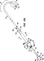
第1図は、本発明の原理に従って構成された冠状動脈口と腕頭動脈との間で上行大動脈を仕切るための血管内装置を示す側面図である。
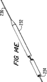
第1A図は、第1図の装置の遠位側部分の端面図であり、成形遠位側部分の傾斜を示すものである。
第1B図及び第1C図は、第1図の装置の成形遠位側部分の別の実施例を示す側面図である。
第2A図は、第1図の装置の遠位側部分の第1実施例を示す斜視図である。
第2B図は、第1図の装置の遠位側部分の第2実施例を示す斜視図である。
第3図及び第4図は、第2A図及び第2B図の3−3線及び4−4線に沿う横断面図である。
第5A図及び第5B図は、第2A図の5−5線に沿う横断面図であり、第2A図に示す装置のシャフトの別の実施例を示すものである。
第6図は、第2B図の6−6線に沿う横断面図である。
第7図は、第1図の装置を大腿動脈、腸骨動脈及び大動脈内に導入し且つ前進させる状態を示す患者の動脈系の一部の正面図である。
第8図は、本発明の原理に従って構成された心臓を停止させる装置の概略図であり、第1図の装置が上行大動脈内に配置され、心停止液供給手段が近位端に連結され且つ心肺バイパスシステムが患者に連結された状態を示すものである。
第9図は、第1図の装置の遠位側部分が上行大動脈内に配置され、その閉塞手段が拡大され且つ組織切断手段が遠位端から拡大された状態を示す図面である。
第10A図及び第10B図は、本発明の原理に従って構成された血管内仕切り装置の別の実施例を示す、それぞれ、側面図及び横断面図である。
第11A図及び第11B図は、本発明の原理に従って構成された血管内仕切り装置の更に別の実施例を示す、それぞれ、側面図及び横断面図である。
第12A図は、本発明の原理に従って構成された血管内仕切り装置の更に別の実施例を示す側面図である。
第12B図は、第12A図の12B−12B線に沿う横断面図であり、シャフトの内部管孔内に配置されたシェーピング要素を示すものである。
第13A図は、本発明の原理に従って構成された血管内仕切り装置の更に別の実施例を示す側面図である。
第13B図は、第13A図の13B−13B線に沿う横断面図である。
第13C図は、第13A図の13C−13C線に沿う横断面図であり、第13A図の装置のバイパスカニューレの血流管孔から大動脈閉塞カテーテルを取り外した状態の血流遮断弁を示すものである。
第13D図は、第13A図の装置の注入チューブに使用する栓塞子及びガイドワイヤを示す斜視図である。
第13E図は、第13A図の仕切り装置を示す側断面図である。
第14A図は、本発明の原理に従って構成された心臓ベンチング装置を示す斜視図である。
第14B図は、第14A図の14B−14B線に沿う横断面図である。
第14C図は、第14A図の14C−14C線に沿う横断面図であり、バイパスカニューレの血流管孔からベンチングカテーテルを取り外した状態の血流遮断弁を示すものである。
第14D図は、第14A図の装置の遠位側部分の別の形状を示す斜視図である。
第14E図は、第14A図の装置の導入を容易にするための栓塞子を示す斜視図である。
第14F図は、第14A図の心臓ベンチング装置を示す側断面図である。
第15A図は、本発明の心臓ベンチング装置の別の実施例を示す側面図である。
第15B図は、第15A図の15B−15B線に沿う横断面図である。
第15C図は、第15A図の装置の遠位側部分の別の形状を示す側面図である。
第15D図は、第15C図の15D−15D線に沿う横断面図である。
第16図は、本発明の方法による大動脈仕切り装置及び心臓ベンチング装置の配置を示す患者の身体の部分切断正面図である。
特定の実施例の詳細な説明
本発明は、種々の心臓血管手術、肺動脈手術、神経外科手術及び他の手術を行なうのに有効な、上行大動脈を仕切るための血管内装置並びに心臓を選択的に停止させる装置を提供する。本発明は、米国特許出願第07/991,188号、第07/730,559号及び第08/023,778号明細書(これらの米国特許出願は、本発明の譲受人に譲渡されており且つ本願に援用する)に記載された、侵襲性が極めて小さい心臓手術にとって特に有効である。本発明の用途を見い出し得る手術として、大動脈弁、僧帽弁及び他の心臓弁の修復又は交換、中隔欠損の修復、肺動脈血栓摘出、電気生理学的マッピング及び剥離、冠状動脈バイパス移植、血管形成、アテレクトミー、動脈瘤の治療並びに神経血管手術及び神経外科手術がある。本発明は、血管内装置を使用するのみで、開胸その他の大きな切開の必要なくして心臓を停止でき且つ患者を心肺バイパスに置くことができる点で特に優れている。また、慣用的な開胸手術においても、本発明の血管内動脈仕切り装置は、外部クロスクランプが、石灰沈着又は他の大動脈条件による塞栓解放の重大な危険を引き起こすことがある場合にしばしば使用される。
ここで、図面を参照して、本発明による上行大動脈を仕切るための血管内装置の好ましい第1実施例を説明する。第1図に示すように、仕切り装置20は、遠位端24及び近位端26を備えたシャフト22を有している。上行大動脈を閉塞するための拡大可能手段28が、遠位端24の近くでシャフト22に取り付けられている。好ましい実施例では、(図面には膨張した状態が示されている)閉塞手段28は、上行大動脈を完全に閉塞するのに適した材料、幾何学的形状及び寸法をもつポリマーバルーン30からなり、後でより詳しく述べるように、収縮期の血流及び拡張期の血流を遮断する。
シャフト22は、大腿動脈又は腸骨動脈に通して導入するのに適した、通常は、約9mm未満の直径を有している。近位端26を体外に配置し、好ましくは鼡径部の大腿動脈又は腸骨動脈から、バルーン30を冠状動脈口と腕頭動脈との間の上行大動脈内内に位置決めするには、シャフト22の長さは約80cm以上(通常は90〜100cm)であるのが好ましい。別の構成として、シャフトは、頸動脈又は上腕動脈に通して、又は動脈自体に穿通して導入するように構成でき、この場合には、シャフトの長さを20〜60cmにすることができる。
仕切り装置20はまた、近位端26と遠位端24との間で延びている第1内部管孔29(第2A図及び第2B図)を有し、該内部管孔29は遠位端24に開口31を有している。遠位端24の近くでシャフト22の側方には、内部管孔29と連通する付加開口を設けることができる。
シャフト22は、遠位端24の開口31が大動脈の内壁から間隔をおいて且つ大動脈弁の中心と軸線方向に整合するように、大動脈弓の曲率とほぼ一致するように形作られた成形遠位側部分32を有している。通常、シャフト22の成形遠位側部分32は、ほぼU字形に形作られて遠位端側セグメント34が、シャフト22のほぼ直線状の近位端側セグメント36により規定される軸線の方向に対して135〜225゜の間の角度、好ましくは約180゜をなして配置されている。通常、成形遠位側部分32は、仕切り装置20が使用される動脈のサイズに応じて(シャフト22の半径中心で測定して)20〜80mmの範囲内の曲率半径を有している。成形遠位側部分32のこの形状は、後でより詳細に説明するように、遠位端側セグメント34が上行大動脈の管腔内で中心に位置し且つ遠位端24が大動脈弁の中心と軸線方向に整合することを可能にし、これにより、液体の注入又は吸引が容易になり且つ動脈壁と干渉することなく開口31を通して手術器具を導入できる。
例示の実施例では、成形遠位側部分32は、応力がかけられていない状態で永久的にほぼU字形形状を維持するように予成形されている。この予成形された形状は、所望の形状をもつマンドレルを第1内部管孔29内に配置し、次いで、シャフト22及びマンドレルを、シャフト22に使用される材料に応じて、これらに永久硬化を生じさせるのに充分な時間、例えば1〜3時間、及び充分な温度、例えば120〜180℃、で焼くか或いは加熱することによって形作られる。
第1B図及び第1C図には、成形遠位側部分32の別の実施例が示されている。第1B図の実施例では、U字形遠位側部分32は、連続した一定の曲率をもつものではなく、直線状又は大きな曲率をもつセグメント35を区分する比較的小さな曲率の屈曲部33を備えたより角張った形態をなしている。屈曲部33及び/又はセグメント35は、大動脈弓の壁と係合して遠位端24を上行大動脈内の所望位置に湾曲させることができる形状にすることもできる。
第1C図の実施例では、成形遠位側部分32は、大動脈弓より上方の位置から上行大動脈内に導入できるように、ほぼ「S」字状の形状に形作られている。このようにすれば、近位端セグメント36が腕頭動脈を通って大動脈弓から頸動脈又は上腕動脈へと延びるようにするか、大動脈自体を穿通して胸腔の外部の位置へと延びるようにして、遠位端セグメント34を上行大動脈内に配置できる。
第1A図に示すように、遠位端セグメント34は、患者の大動脈弓の形状に更に一致し且つ大動脈弁の中心と更に整合するため、近位端セグメント36の長手方向中心軸線に対して傾斜させる(同一平面内にないようにする)のがよい。例示の実施例では、遠位端セグメント34は、近位端セグメント36の中心軸線を含む平面に対して角度αをなして配置されている。ここで、角度αは、2〜30゜、通常は10〜20゜、好ましくは約15゜である。しかしながら、成形遠位側部分32の形状及び寸法及び遠位側セグメント34の角度αは、個々の患者の大動脈弓の形状に従って変えることができる。
好ましい実施例では、装置は、遠位端24に取り付けられた柔軟チップ38を有し、該チップ38は、装置が心臓組織に接触したときに、心臓組織、より詳しくは、大動脈弁の弁葉(leaflets)を傷つける危険性を低減させる。柔軟チップ38は、遠位端方向に向かって直線状又はテーパ状をなしており、シャフト22の遠位端24の開口31と整合した軸線方向通路を備えている。柔軟チップ38は、65ショア硬度A〜35ショア硬度Dの範囲の硬度をもつポリウレタン又はPebax等の低硬度ポリマーであるのが好ましい。
上行大動脈内でのバルーン30の位置決めを行なうX線透視視認を容易にするため、シャフト22の遠位端24の近くには少なくとも1つのX線不透過ストライプすなわちマーカ39を設けるのが好ましい。X線不透過マーカ39は、プラチナその他のX線不透過材料のバンドで構成できる。別の構成として、シャフト22に使用されるポリマーにバリウム塩又はビスマス塩の増量剤を添加して、X線不透過性を与えることもできる。
第1図、第2A図及び第2B図に示すように、シャフト22の第1内部管孔29内には、シャフトに対して長手方向に摺動できるように、くせ取り要素即ち直線化要素(strai−ghtening element)40が配置される。くせ取り要素即ち直線化要素40は、後述するように、ガイドワイヤ42を受け入れるための長手方向通路44を備えた管状スタイレットを備えているのがよい。或いは、要素40は、ガイドワイヤ自体の比較的剛性の高い部分で構成してもよい。くせ取り要素即ち直線化要素40は、シャフト22の曲げ剛性より大きい曲げ剛性を有する、ポリマー材料又はステンレス鋼又はニッケルチタン合金等の生体適合性金属で構成するのがよい。このようにして、くせ取り要素即ち直線化要素40は予形成された遠位側部分32に向かって遠位側に前進させられてシャフト22を直線状にし、仕切り装置20の動脈内への皮下導入及び大動脈弓への前進を容易にする。次に、くせ取り要素即ち直線化要素40をシャフトに対して近位側に後退させることができ、これにより、予形成された遠位側部分32は大動脈弓の形状と一致した状態で、遠位端24が上行大動脈内に位置決めされる。
可動ガイドワイヤ42が、くせ取り要素即ち直線化要素40の長手方向通路44を通して(第2B図)、又はくせ取り要素即ち直線化要素40の外部で且つくせ取り要素即ち直線化要素40に対して平行に、シャフト22の別の管孔(図示せず)を通って、第1内部管孔29の中に摺動可能に配置される。ガイドワイヤ42は、シャフト22より遠位端24の開口31を通って延び且つシャフト22より遠位側の動脈内に前進させられ、これにより、ガイドワイヤ上でシャフトを摺動させることにより、シャフト22を、動脈を通って上行大動脈へ前進させるのが容易になる。ある実施例では、ガイドワイヤ42の剛性が比較的大きく、これによりシャフト22が少なくとも部分的に直線状にされるため、くせ取り要素即ち直線化要素40を用いないでシャフト22を導入することもできる。この実施例では、ガイドワイヤ42を、例えば、約1.0〜1.6mmの直径をもつステンレス鋼又はニッケルチタン合金で形成するのがよい。
シャフト22は、行なわれる手術に応じて、任意の種々の構造にすることができる。一実施例では、シャフト22は、第2A図、第3図及び第5A図に示すように、単一押出しで成形された3つの非同心状の平行な管孔を備えた多管孔構造を有している。3つの管孔は、くせ取り要素即ち直線化要素40及びガイドワイヤ42を受け入れ且つ遠位端に開口31を備えた第1内部管孔29と、シャフト22の遠位端の近くでバルーン30の内部と連通している膨張オリフィス47に開口する膨張管孔46と、上行大動脈内の圧力を検出するためシャフトの遠位端24に開口(図示せず)をもつ第3管孔48とからなる。この実施例では、第1内部管孔29の最大横方向寸法は約1〜4mmが好ましい。第3管孔48の遠位側開口は、第1内部管孔29の開口31から半径方向にオフセットされており、これにより、第1内部管孔29を通る液体の注入及び吸引が、第3管孔48を介して行なわれる圧力測定に影響を与えないようになっている。
第5B図に示される第2実施例では、シャフト22が、二重管孔内側部材50と、これと同心状の外側部材52とを有している。内側部材50は、くせ取り要素即ち直線化要素40を受け入れ且つ遠位側開口31で開口している第1内部管孔29と、上行大動脈内の圧力を測定するための遠位端に設けられた開口(図示せず)をもつ第3管孔54とを有している。外側部材52は同心状の膨張管孔56を有し、該膨張管孔56は、その遠位端がバルーン30の内部と連通している。バルーン30及び外側部材52を単一一体押出しで成形しても、よく、あるいはバルーン30を良く知られた技術を用いて、シャフト22の遠位端の近くで外側部材52に接着又は取り付けてもよい。外側部材52には、バルーン30の内部と連通する開放した遠位端を設けてもよい。或いは、膨張管孔56とバルーンの内部とを連通させるための第2A図に示すような膨張オリフィス47を設け、外側部材52の遠位端を、例えば内側部材50の外面に接着させることにより閉鎖してもよい。
第2B図、第4図及び第6図に示す第3実施例では、シャフト22は大きな直径の第1内部管孔29を有し、種々の形式の手術器具並びにくせ取り要素即ち直線化要素40を受け入れることができるように形作られている。膨張管孔58は、第1内部管孔29と平行に延び且つ第2B図に示すように膨張オリフィス61を介してバルーン30の内部と連通している。この実施例では、シャフト22は、膨張管孔58及び内部管孔29を備えた単一押出し体として構成するか、管孔29を備えた一方のチューブと、膨張管孔58を備えた他方のチューブである2本のチューブを相互に接合して構成することができる。この構造によれば、装置が位置決めされる血管の範囲内で管孔29をできる限り大きくすると同時に、シャフトの輪郭を最小にすることができる。この実施例では、第1内部管孔29は、少なくとも約5mm、好ましくは約8mmの直径を有することになる。これにより、仕切り装置20は、係属中の米国特許出願第07/991,188号(該米国特許出願は本願に援用する)に記載されているように、視認スコープ、吸引器、洗浄チューブ、切断器具、ステープリング器具及び縫合器具等の手術器具の血管内導入ができる最大直径の通路を提供している。
第2B図、第4図及び第6図に示すように、幾つかの実施例では、半径方向の剛性を増大させ且つ第1内部管孔29の横方向寸法を維持するために、シャフト22の壁中にワイヤ編組又はコイル60を埋設することができる。手術器具が導入されることになる第1内部管孔29の丸みを維持することは特に重要である。シャフト22が管孔29を通してこれらの器具を収容できるのに充分な直径に作られているならば、シャフトは、大動脈弓の湾曲領域内に前進させられたときに、平らになるか、捩れてもよい。管孔の丸みを維持するワイヤ編組又はコイル60の使用により、器具の輪郭を最大にでき且つ最小の干渉で器具を管孔の中に前進させることができる。ワイヤ編組又はコイル60は、ステンレス鋼又はニッケルチキン合金のような生体適合性材料、ケブラー(デュポン社の商標)のようなアラミド繊維又はナイロンで形成するのがよい。
シャフト22は、ポリウレタン、ポリ塩化ビニル、ポリエーテルブロックアミド又はポリエチレン等の生体適合性ポリマーを含む種々の材料で構成できる。第2A図に示す装置の好ましい実施例では、シャフト22は、50D〜80Dのショア硬度をもつウレタンである。第2B図の実施例では、シャフト22が、剛性を増大させるを非常に大きな直径及び埋設コイルを有し、また、60A〜100Aのショア硬度をもつポリウレタンが使用されるのがよい。シャフト22は、70〜100kpsi、好ましくは、約80〜90kpsi、の範囲の曲げ剛性係数(bending modulus)をもつのがよい。この範囲の曲げ剛性係数は、大腿動脈又は腸骨動脈から上行大動脈への押込み可能性(pusha−bility)を最適化するのに充分な剛性を与えると同時に、曲がりくねった腸骨動脈及び大動脈弓を進行するのに充分な可撓性を与える。ひとたび、仕切り装置20の遠位端24が上行大動脈内に位置決めされると、この曲げ剛性係数はまた、バルーン30が膨張させられたときに左心室からの血液の流出に抗してバルーン30の位置を維持するために、遠位側を向いた力を近位端26からシャフト22に加えることを容易にする。他の実施例では、シャフト22が種々の領域で、変化させることができる曲げ剛性をもつようにするため、シャフトの長さ方向に沿ってシャフト並びにコイル60の寸法、幾何学的形状及び/又は材料を変えてもよい。例えば、大動脈弓を通る追随性のため、予形成される遠位側部分32の可撓性を一層高める一方、押込み可能性を向上させ且つ配置時の抵抗を低減させるため、近位側部分36の剛性を高めることができる。
バルーン30は種々の材料で且つ種々の幾何学的形状に構成できる。好ましい実施例では、バルーン30は、大腿動脈又は腸骨動脈内に導入するのに充分小さい、例えば外径4〜9mmの折畳み輪郭、及び上行大動脈を完全に閉塞するのに充分大きい例えば20〜40mmの拡大(膨張)輪郭を有している。折畳み輪郭の直径に対する拡大輪郭の直径の比率は、2〜10の間、好ましくは5〜10の間になる。また、バルーンは、バルーンが拡大したときに、バルーンの変位を妨げ且つバルーンの周囲の漏洩を最小にするため、大動脈壁とバルーンの作用面との接触を最大にして、好ましくは約3〜7cmの範囲の軸線方向長さをもった作用面が得られるように形作られている。バルーンの作用面に、リブ、隆起又はこぶ等の構造的な特徴を付与し、摩擦効果を高めて変位に対する抵抗を一層高めてもよい。
バルーン30は、単一バルーンで種々の直径の動脈に適用できるようにするため、或る程度の半径方向の膨張又は伸長ができることが好ましい。バルーン30に使用できる材料として、ポリウレタン、ポリエチレンテレフタレート(PET)、ポリ塩化ビニル(PVC)、ラテックス、エチレン酢酸ビニル(EVA)等がある。しかしながら、バルーン30は、上行大動脈を通る血流から収縮圧力を受けたときに、バルーンの全体的形状及びシャフト22に対する位置を維持できるようにするため、充分な構造的一体性を有していなければならない。例示した実施例では、バルーン30は、ポリウレタン、又は、ポリウレタンとPVCあるいはEVA等のポリビニルとのブレンドで作られている。このような材料は、一定範囲の血管直径に適合できるのに充分な弾性的な伸びを有すると同時に、左心室からの血液検出を受けるときに上行大動脈内でのバルーンの形状及び位置を維持できるのに充分な構造的一体性を有することが判明している。
好ましい実施例では、バルーン30に、更に、第3図及び第4図に示すような複数の折畳み部すなわち襞(ひだ)62が設けられており、これらの折畳み部及び襞62は、バルーンが、真空引きにより、大腿動脈又は腸骨動脈に導入できる小さな折畳み輪郭に折り畳まれることを可能にする。この実施例では、バルーン30は、約200〜400%、好ましくは約300〜400%、の(収縮時(折畳み前)の外径に対する完全膨張時の外径の比率として定義される)膨張比を有している。好ましくは、少なくとも3つの襞62が設けられ各襞は、収縮した(しかしながら、バルーンの内部の真空引きにより折り畳まれない)ときのバルーンの周囲の約5〜25%に相当する幅を有している。襞62は、周面に縦溝が設けられたディッピングマンドレルを用いて、バルーン製造工程時にバルーンに形成されるのがよい。液状のバルーン材料(例えばポリウレタン)の容器内にマンドレルを浸漬すると、バルーン材料の管状層がマンドレル上で凝固し、縦溝の形状に一致する。次いで、マンドレルを取り除くと、ほぼ一定厚さを有する襞付きバルーンが製造される。襞付きバルーンではなく、折畳み形バルーンを使用する場合には、折畳み部は、バルーンの製造後に、バルーンをマンドレル上で所望の折畳み輪郭に真空折畳みを行ない且つバルーンを加熱することにより、又は、波形金型内で加圧及び加熱してバルーンを拡大することにより製造されるのがよい。
別の実施例では、閉塞手段28は、プルワイヤ、トルクケーブル又は機械的アクチュエータ、流体圧力アクチュエータ、電気的アクチュエータ又は形状記憶アクチュエータにより操作される枢動傘形又はファン形閉塞機構を含む任意の種々の構造で構成してもよい。また、閉塞手段28は、シャフト22上で前後に並べて配置される多数の閉塞具で構成してもよい(例えば、シャフトの遠位端で1対のバルーンを前後に配置できる)。一実施例では、一般譲渡された係属中の 年 月 日付米国特許出願第 号(名称「心臓手術を行なう装置(System for Performing a Cardiac Procedure)」、代理人受理番号18409.003.01)に記載されているように、閉塞バルーンは、上行大動脈内に配置されるようにシャフト上に取り付けられ、一方、この閉塞バルーンの前方には座合バルーンが配置され、大動脈弁を通って左心室内に配置されるようになっている。尚、この米国特許出願の全開示内容を本願に援用する。左心室内で座合バルーンを膨張させることにより、左心室からの血液流出に抗して、上行大動脈内での閉塞バルーンの位置を維持することができる。
再び第1図を参照すると、シャフト22の近位端26には、3アーム形アダプタ64が取り付けられている。3アーム形アダプタ64は第1内部管孔29と連通する作業ポート66を有し、後述するように、作業ポート66を通して、くせ取り要素即ち直線化要素40、ガイドワイヤ42及び或る実施例では手術器具又は診断器具が導入される。また、作業ポート66は、第1内部管孔29を介して、心停止液、食塩水又はコントラスト溶液の注入、並びに血液、体液及び剥離屑の吸引を行なうことができるように構成されている。また、3アーム形アダプタ64は、膨張管孔と連通しており且つ注射器70のような膨張流体供給器具に連結できる形状を有する膨張ポート68を有している。圧力測定ポート72が第3管孔(48又は54)と連通しており且つ圧力測定装置に連結できるようになっている。別の構成として、シャフト22が、第2B図、第4図及び第6図に示すように第1内部管孔29及び膨張管孔58のみを有する場合には、ポート72を第1内部管孔29と連通させ、圧力測定及び流体の注入又は吸引を行なうように構成してもよい。
ここで第7図〜第9図を参照して、本発明の方法の好ましい実施例を説明する。最初に、特定患者に適したサイズ及び形状をもつ仕切り装置20を選択しなければならない。通常、患者の大動脈はX線透視イメージングにより観察され、そのサイズ及び形状、特に大動脈弓の領域におけるサイズ及び形状が決定される。仕切り装置20は、閉塞手段28が、鼡径部における大腿動脈又は腸骨動脈であるのが好ましい導入点から上行大動脈内に進むのに充分な長さをもつように選択される。また、仕切り装置は、遠位端24が上行大動脈の内壁から間隔をおき、好ましくは大動脈弓の中心と整合するように、遠位端を患者の大動脈弓内で位置決めするのに適した寸法及び形状をもつ予形成された遠位側部分32を有するものが選択される。通常、予形成された遠位側部分は、大動脈の中心で測定した大動脈弓の曲率半径にほぼ等しい好ましくは、約±10mmの公差内の、曲率半径、を有することになる。
第7図に示すように、仕切り装置20は、既知の切開又はセルジンガー術(Seldinger technique)のような皮下技術を用いて、鼡径部の大腿動脈74又は腸骨動脈内に皮下挿入されるのが好ましい。最初にガイドワイヤ42を大腿動脈74内に導入し、そして、腸骨動脈76及び大動脈78を通って心臓に向かって前進させ、ガイドワイヤ42の遠位端を上行大動脈(第7図には示されていない)に到達させる。くせ取り要素即ち直線化要素40をシャフト22の管孔29内に挿入し、予形成された遠位側部分32を直線状にするように、該遠位側部分32内に位置決めする。バルーン30が収縮された状態で、シャフト22がガイドワイヤ42上に位置決めされ、大腿動脈74内に導入され、且つガイドワイヤ42上で腸骨動脈76及び大動脈78の中を前進させられる。シャフト22のX線不透過マーカ39の視認を行なうためにX線透視装置を用いて位置決めを容易にするのがよい。X線透視イメージングに代えて又はこれを補完するため、例えば食道内に超音波心臓検査変換器を配置して、超音波心臓検査法を用いてもよい。
シャフト22を、大腿動脈又は腸骨動脈ではなく、頸動脈87又は上腕動脈89内に導入してもよい。この場合には、シャフト22の遠位側部分32は、通常、第1C図に関連して前述した全体としてS字形の形状を有することになる。このようなS字形形状は、シャフト22を腕頭動脈86に通して大動脈弓から上方(頭頂に近い方)に配置することにより、上行大動脈内でのバルーン30の位置決めを容易にする。
第8図及び第9図に示すように、シャフト22は、バルーン30が冠状動脈口84と腕頭動脈86との間の上行大動脈82内に位置するまで、大動脈弓80の中を進められる。遠位端24が大動脈弓80の回りを進められると、くせ取り要素即ち直線化要素40がシャフト22に対して近位側に引き出され、予形成された遠位側部分32が大動脈弓の形状に一致するようにする。他の実施例では、別体のくせ取り要素即ち直線化要素を使用しないで、比較的剛性の高いガイドワイヤを使用することができ、この場合には、ガイドワイヤは、シャフト22が上行大動脈内に進められるときに所定位置に留まる。次いで、くせ取り要素即ち直線化要素40及びガイドワイヤ42をシャフト22から取り除くのがよい。
別の技術では、仕切り装置20を、胸腔鏡を用いて大動脈内に導入してもよい。この実施例では、シャフト22の遠位端24は、小さな切開部又はカニューレを通って胸腔内に導入される。上行領域又は大動脈弓のいずれかに、小さな穿通が大動脈に形成される。次いで、小さな切開部又はカニューレを通って胸腔内に導入される鉗子又は他の胸腔鏡器具を用いて、シャフト22を大動脈内に挿入する。このような技術は、患者の大腿動脈又は腸骨動脈が、仕切り装置20を経皮的に又は切開により血管内に導入するのに適していない場合に有効である。
第8図に示すように、バルーン30が冠状動脈口84と腕頭動脈86との間の上行大動脈82内に位置決めされるよう、シャフト22を位置決めして、バルーン30を、注射器70から膨張ポート68を通して膨張流体、通常は、X線写真造影剤を含む食塩水、を注入することにより膨張させる。例示の実施例では、バルーンは、使用される膨張管孔のサイズ及び膨張流体の粘度にもよるが、約5〜15秒で完全に膨張させられる。或る実施例では、血液が内部管孔29を通って(後述する)心肺バイパスシステム94へと流れることができ、これにより、膨張中にバルーン30に作用する血流圧力が低減される。完全に膨張すると、バルーン30の外面が上行大動脈の内壁と接触し、これにより血管を完全に閉塞し且つバルーンを通り越す収縮期及び拡張期のほぼ全ての血流の流れブロックする。心臓が鼓動を維持している間、血液は、左心室から大動脈弁を通って冠状動脈口へと流れることができ、冠状動脈を通って心筋層を灌流する。かくして、心臓及び冠状動脈は、動脈系の残部から隔絶される。
別の実施例では、膨張速度を増大させるため、ガス状膨張流体が使用される。これにより、バルーン30は心収縮期脈間の期間より短い時間で完全に膨張され、従って、収縮期の左心室からの血液流出によって上行大動脈内でバルーン30が定位置から変位する傾向が緩和される。膨張流体としてはヘリウムを使用するのが好ましい。なぜならば、ヘリウムは血液中に高度に溶解するため、バルーンから漏洩するようなことがあっても、潜在的に有害なガス塞栓を形成し難いからである。膨張ポート68を通して加圧ヘリウムを供給するには、米国特許第4,771,765号及び第4,902,272号(これらの米国特許は、本願に援用する)に開示されたものと同様なガス膨張ポンプ及び制御装置を使用するのがよい。膨張ポンプは、心収縮期脈間でのバルーンの膨張を容易にするため、心臓の収縮にタイミングを合わせることができる。このようなポンプを使用すれば、バルーン30を約1秒以内、好ましくは約0.5秒以内に完全膨張させることができる。
第8図は、本発明の原理に従って構成された心停止装置の構成要素を示す。作業ポート66には心停止液供給装置90が連結される。第1内部管孔29(又はシャフト22の独立した第3管孔)を介してバルーン30の上流側の上行大動脈内の圧力をモニタするため、ポート72には圧力測定装置92を連結できる。身体の全体に亘る酸素化血の循環を維持するため、患者は、心肺バイパス(CPB)システム94に連結される。通常、脱酸素血を引出すため、大腿静脈には静脈カニューレ96が位置決めされる。また、肺動脈幹内に収容された血液を引出し、これによって、左心房を減圧させるため、右側内頸静脈に通して肺動脈幹内に肺動脈ベンチングカテーテル(図示せず)を配置してもよい。引出された血液は、二酸素化炭素を除去し且つ血液を酸素化させるCPBシステム94に送られる。次いで、酸素化された血液(酸素化血)は、次に、動脈カニューレ98を介して大腿動脈又は腸骨動脈に送られる。心停止液を送る前、又は後、に第1内部管孔29から血液、他の流体及び剥離屑を受け入れ、血液を濾過して、不純物を除去し、そして血液をCPBシステム94に送って患者の循環器系に戻すため、血液濾過/回収装置100を、切換えスイッチ101を介して仕切り装置20のポート66に連結してもよい。本発明の装置での使用に適したCPBシステムの他の特徴は、前述の米国特許出願第07/991,188号明細書並びにF.Rossi等の「全心不全のモデルにおける末梢カニューレ挿入による長期心肺バイパス(Long−Term Car−diopulmonary Bypass By Peripheral Cannulation In A Model of Total Heart Failure)」(Journal of Thoracic and Cardiovascular Surgery(1990),100:第914〜921頁)、米国特許第4,540,399号及び第5,011,469号明細書(これらは全て本願に援用する)に記載されている。
CPBを確立させかつ上行大動脈を通る血流のブロックした状態で、次いで、心筋層が麻痺されるであろう。好ましい実施例では、塩化カリウム(KCl)のような心停止液が、供給装置90により作業ポート66を介して送られる。好ましくは、供給装置90は、心臓を例えば5〜10℃の低温に維持し且つ酸素要求を最小にするために、心停止液を冷却するクーラ(図示せず)を有している。これは、通常、慣用的な開胸心臓手術で行なわれているような心臓の外部冷却をすることなく行なわれる。心停止液は、仕切り装置20の遠位端の開口31を通って上行大動脈内に注入される。また、心停止液は、前述の米国特許出願第07/991,188号明細書に記載されているように、右側内頸静脈を通る管孔を介して位置決めされるカテーテル(図示せず)を用いて、冠状静脈洞を通る逆態様で注入することもできる。次いで、心臓収縮が停止し、患者の身体の残部への血液循環はCPBシステム94により維持される。患者の心筋層への心停止液の流れは、心筋層が麻痺している限り、周期的(例えば約20分毎)に維持される。
KClの注入に加え又はKClの代わりに、他の技術を用いて心臓収縮を停止させてもよい。患者の身体は、低温環境中で冷却するか、胸部にコールドパックを塗布することにより冷却し、線維攣縮(fibrillation)を誘起させるのに充分な温度に心筋層を低下させることができる。心筋層は、冠状動脈を通して食塩水のような冷たい流体を注入することにより、直接冷却することができる。或いは、心臓の外面又は胸部に外的に取り付けられた電極により電気信号を心筋層に送り、電気的線維攣縮を達成することができる。しかしながら、線維攣縮による心停止は、外科的介入をより困難にする心運動が或る程度残ってしまうこと、及び酸素要求量がかなり大きく、手術の安全性及び時間が短縮されてしまうことから、化学的心停止麻痺より好ましくない。
心臓が停止され且つCPBが確立されると、外科手術を遂行する。手術は、本願に援用する米国特許出願第07/991,188号及び第08/023,778号明細書に記載されているように、血管内的に又は胸腔鏡を用いて行なわれる侵襲性の小さい手術であるのが好ましい。本発明の装置及びシステムを用いて行なう外科的手術として、大動脈弁、僧帽弁及び他の心臓弁の修復及び交換、心室及び心房の中隔欠損の補修、中隔の筋内解剖、不整脈を矯正するための心臓マッピング及び切除、冠状動脈バイパス移植、血管形成、アテレクトミー、肺動脈手術、脳神経外科的手術及び他の手術がある。
本発明の仕切り装置20は、心臓弁の補修及び交換等の手術を行なうため大動脈に通して手術器具の血管内導入を行なうのに特に有効である。第9図に示すように、シャフト22の予形成された遠位側部分32は、大動脈弓80の形状に一致し、これにより、遠位端の開口31が上行大動脈内で中央に配置され且つ大動脈弁104の中心と軸線方向に整合する。これは、開口31を通る心停止液の注入を高めるだけでなく、弁の切除又は心臓内手術を行なうために第1内部管孔29を通って導入される弁カッタ106のような手術器具を大動脈弁104と確実に整合させることになる。シャフト22の遠位端の柔軟チップ38が大動脈弁の傷付き易い弁葉と接触して、組織に損傷を与えることを防止するので優れている。
本願に開示する仕切り装置及び心臓を停止させるシステムは、血管内的に及び/又は胸腔鏡を用いて行なわれる侵襲性の小さい心臓手術において特に有効であるけれども、開胸により行なわれる慣用的な手術にも有効である。仕切り装置20は、大動脈クロスクランプが石灰沈着又は他の大動脈条件による塞栓の解放を引き起こす危険性がある場合にも使用できる。開胸手術では、仕切り装置20は、前述のように、大腿動脈又は腸骨動脈を通って導入され、更に頸動脈87、上腕動脈89又は開胸術の結果としてアクセスできる大動脈自体への穿通を介して導入される。これらの場合には、仕切り装置20のシャフト22を、例えば20〜60cmのようにかなり短くすることができる。
手術が完了すると、仕切り装置20を通る心停止液のあらゆる流れを遮断するか冠状静脈洞を通して逆流させ、肺に通気し、冠状動脈に暖かい血液を灌流させることにより、心臓の活動を再開させる。バルーン30の上流側の領域は、第1内部管孔29を通して食塩水を注入することにより洗浄することができる。次いで、手術中に形成されたかもしれない血栓又は他の塞栓を除去すべく、バルーン30の上流側の血液及び他の流体を第1内部管孔29を通して吸引し、これらの塞栓が腕頭動脈、頸動脈又は鎖骨下動脈に流入することを防止して発作のような合併症が生じる危険性を大幅に低下させる。バルーン30を収縮させ、通常の暖かい血流が上行大動脈を通って動脈系の残部に流れ得るようにする。正常な心臓の収縮が直ぐに再開されるかもしれない、あるいは、もし、必要ならば、電気線維攣縮を施して、心臓のリズムを矯正する。CPBを徐々に停止し、CPB静脈カニューレ96及びCPB動脈カニューレを取り外す。仕切り装置20を入口部位から引き出し、動脈穿通を閉鎖する。患者が一般的な知覚麻痺状態にある場合には、患者を麻痺状態から意識回復させる。
当業者ならば、本発明の範囲から逸脱することなく、本発明の血管内仕切り装置20の種々の別の構成を考え得るであろう。そのような他の実施例の一例が第10A図及び第10B図に示されている。この実施例では、仕切り装置20が、シャフト22の管孔112内に配置されたプルワイヤ110を有している。プルワイヤ110は、その遠位端が、シャフト22の遠位端24でアンカー板114に取り付けられており、好ましくは、シャフト22の長手方向中心軸線からオフセットしている。一実施例では、プルワイヤ110は、アンカー板114の孔の中を延びており且つプルワイヤ110の遠位端に固定されたボール116によりアンカー板に保持されている。他の点については、仕切り装置20は第1図〜第9図に関連して説明したように構成されており、遠位端24の近くでシャフト22に取り付けられたバルーン30と、バルーン30の内部と連通する膨張管孔118と、シャフト22の遠位端24に取り付けられた柔軟チップ38と、遠位側開口31と連通する内部管孔29とを有している。プルワイヤ110の近位端(図示せず)に張力を加えて、シャフト22の遠位側部分32を、大動脈弓内に位置決めするのに適した形状(第10A図に破線で示す形状)に撓ませる。別の実施例では、プルワイヤ110の代わりに、軸線方向には剛性があり且つ横方向には湾曲させることができるロッドが使用され、これにより、ロッドに圧縮力を加えることにより遠位端24を撓ませることができる。
湾曲していない形状(プルワイヤ110に張力を加えていないとき)では、シャフトの遠位側部分32はほぼ直線状になっている。別の構成として、大動脈弓内での位置決め容易性を高めるため、湾曲していない状態においても遠位側部分32の全部又は一部が湾曲した状態になるようにしてもよい。プルワイヤ110に張力を加え且つ遠位側部分32を所望形状に維持すべくプルワイヤをロックする機構(図示せず)をシャフト22の近位端に設けるのが好ましい。この機構として、米国特許第5,030,204号明細書に記載された種々の機構を使用できる。通常、シャフト22は、ほぼ直線の状態で動脈内に導入され、シャフトが大動脈弓内に進められるとプルワイヤ110に張力を加えて遠位側部分32を湾曲させる。遠位側部分32が大動脈弓内に位置決めされると、プルワイヤ110に加えた張力を調節して、遠位端24が上行大動脈内で半径方向に位置するようにし、大動脈の内壁から間隔があけ且つ大動脈弁の中心と軸線方向に整合するようにする。次いで、プルワイヤ110を張力付与状態にロックして遠位側部分32をその湾曲状態に維持する。
第11A図及び第11B図には、仕切り装置20の更に別の実施例が示されている。この実施例では、ガイドカテーテル122の内部管孔120内にシャフト22を配置できる。この装置20は第1図〜第6図に関連して前述した装置と同様に構成され、遠位端24の近くのバルーン30と、内部管孔29と、膨張管孔46と、圧力管孔48と、遠位端24に取り付けられた柔軟チップ38と、近位端26に取り付けられた3アーム形アダプタ64とを有している。ガイドカテーテル122は、近位端124と、遠位端126とを有しこれらの間に軸線方向管孔120が延びている。大動脈又は大動脈弁と接触した場合に、これらに与える損傷を最小にするため、遠位端126には柔軟チップ(図示せず)を取り付けることができる。近位端124には近位側アダプタ128が取り付けられており、該近位側アダプタ128は、シャフト22を導入できる管孔120と連通している第1ポート130と、流体の注入及び吸引を行なうための、管孔120と連通している第2ポート132とを有している。また、ポート130は止血弁を有してもよい。また、ガイドカテーテル122は大動脈弓の形状にほぼ一致する形状に予形成されるか、この形状に湾曲させることができる遠位側部分134を有する。ガイドカテーテル122の遠位側部分134を予形成するか湾曲させるのに適した技術は、第1図〜第6図及び第10A図及び第10B図に関連して前述したものである。例示実施例では、ガイドカテーテル122が、20〜80mmの範囲の曲率半径をもつほぼU字形の形状に予形成されている。この実施例では、ガイドカテーテル122を動脈内に皮下導入する目的で遠位側部分134を直線状にするための、第1図〜第6図に関連して上述したようなスタイレット(図示せず)が設けられる。
使用に際し、ガイドカテーテル122は、動脈、例えば、大腿動脈又は腸骨動脈内に導入され且つ遠位端126が上行大動脈内に位置するまで心臓に向かって進められる。追随性を高めるため、ガイドワイヤ(図示せず)を使用してもよい。皮下導入するため、スタイレットを用いて予形成ガイドカテーテルを直線状にした場合には、予形成された遠位側部分134が大動脈弓を通って進められたときにスタイレットが引き出される。ひとたびガイドカテーテル122が所定位置を占めると、シャフト22をポート130及び管孔120を通して導入し且つバルーン30がガイドカテーテル122の遠位端126より遠位側の冠状動脈口と腕頭動脈との間に配置されるまで心臓に向けて進める。シャフト22の遠位側部分32(第1図)は、ガイドカテーテル122の予形成部分134により、大動脈弓に一致する形状に形作られる。次いでバルーン30を膨張させ、上行大動脈を完全に閉塞し且つ該上行大動脈を通る血流をブロックする。
第12A図及び第12B図に示す更に別の実施例では、仕切り装置20が、第3内部管孔48のようなシャフト22の管孔内に配置されたシェーピング要素140を有している。シェーピング要素140は、近位端142と、遠位端144と、予形成された遠位側部分146とを有している。予形成された遠位側部分146は、応力を受けていない状態(非応力状態)で、患者の大動脈弓の少なくとも一部にほぼ一致するように遠位側部分32を形成し、図示のようにほぼU字形になるか、又は、ある角度をもつか、S字形あるいは他の形状になるように構成されているのがよい。遠位側部分32を所望の形状に湾曲させるように、シェーピング要素140は、シャフト22の曲げ剛性より大きい曲げ剛性をもつステンレス鋼、ニッケルチタン合金又は他の生体適合性材料であるのが好ましい。シェーピング要素140は、その上でシャフト22が上行大動脈へと進められるガイドワイヤであるか、又はバルーン30が上行大動脈内に位置するようにシャフト22が位置決めされた後、第3内部管孔48内に挿入されるスタイレットであるのがよい。好ましい実施例では、シェーピング要素140は、シャフト22の遠位端24を、上行大動脈の内壁から間隔をあけるように且つ特に、大動脈弁の中心と軸線方向に整合するように上行大動脈内の半径方向位置に位置決めするように形作られている。
第13A図〜第13E図に示す本発明の他の態様では、仕切り装置20が動脈バイパスカニューレ150に連結される。動脈バイパスカニューレ150は、酸素化血を患者の動脈系に供給するための心肺バイパスシステムに連結できるように構成されている。動脈バイパスカニューレ150は、遠位端152と、近位端154と、近位端154と遠位端152との間に延びている血流管孔156と、遠位端152の流出ポート158とを有している。動脈バイパスカニューレ150に沿って、より詳しくは、遠位端152の近くに、複数の付加流出ポート160を設けることができる。好ましい実施例では、動脈バイパスカニューレ150は、約10〜60cmの間、好ましくは約15〜30cmの間の長さを有する。
アダプタ162は、バイパスカニューレ150の近位端154に連結され且つ第1アクセスポート164及び第2アクセスポート166とを有しており、両アクセスポートは、血流管孔156と連通している。アクセスポート166は、心肺バイパスシステムからのチューブに流体連結できるように構成され、好ましくは逆目フィッティング168を有する。アクセスポート164は、これに通される仕切り装置20を受け入れることができるように構成されている。好ましくは、第13C図及び第13E図に示す止血弁170はアクセスポート164に取付けられ、仕切り装置20のシャフト22がアクセスポート164に配置されているか否かに係わらず、アクセスポート164から血液その他の流体が漏洩することを防止している。止血弁170は公知の構造にすることができ、例えば、これを通してシャフト22が位置決めされる1つ以上のスリット172を備えたエラストマディスク169と、該ディスクに隣接し且つシャフト22の外周面をシールする中央孔174を備えたダイアフラム171とを有している。この形式の止血弁は、本願に援用する米国特許第4,000,739号明細書に開示されている。ダックビル弁、Oリングシール、及び回転又は摺動機械弁等の他の形式の止血弁を使用することもできる。また、回転可能なねじキャップ175を備えたトーヒ−ボースト弁(Touhy−Borst valve)173をアクセスポート164の近位端に設けることができ、これにより、キャップ175を締めつけることによりOリング177をシャフト22の周囲に押しつけて、容易にシャフト22をクランプし且つシールすることができる。
仕切り装置20のシャフト22及びバイパスカニューレ150の血流管孔156は、心臓の活動を完全に停止させ且つ好ましくない溶血レベルを生じさせることがなく、完全な心肺バイパスをサポートするのに、充分な血流が血流管孔156を通って流れるように形作られかつ寸法決めされている。好ましい実施例では、動脈バイパスカニューレ150は6〜10mmの外径を有し、血流管孔156は5〜9mmの内径を有している。仕切り装置20のシャフト22は、2〜5mmの範囲の外径を有している。これにより、その中にシャフト22が配置される血流管孔156は、約250mmHg以下の圧力で少なくとも毎分約4lの血流量が容易に得られる。
仕切り装置20を血流管孔156から取り外した状態で、動脈バイパスカニューレ150を、動脈、通常は大腿動脈、内に導入するのが好ましい。血流管孔156には、第13D図に示す栓塞子176をそのテーパ状遠位端178が動脈バイパスカニューレ150の遠位端152から遠位側に向かって延びるように配置されるように位置決めするのがよい。動脈バイパスカニューレ150は、セルジンガー術のような経皮的方法を含む種々の技術により動脈内に導入されるけれども、通常、外科的切開を必要とする充分なサイズを有している。動脈バイパスカニューレ150の導入を容易にするために、ガイドワイヤを、栓塞子176の管孔182に通して摺動可能に位置決めするのがよい。ガイドワイヤを動脈切開を通して動脈内に前進させ、そして、中に栓塞子176が位置決めされている動脈バイパスカニューレ150をガイドワイヤ上で動脈内に進める。次いで、栓塞子176を取り外せば、仕切り装置20を、血流管孔156を通して、通常はガイドワイヤ上で、動脈内に導入できる。上行大動脈内での仕切り装置20の遠位端24の位置決めを容易にするために、ガイドワイヤを心臓に向かって上行大動脈内へ進めるのがよい。
別の実施例では、動脈バイパスカニューレ150は、仕切り装置20を血流管孔156から取外しできないように構成されている。この実施例では、バイパスカニューレ150は、血流管孔156内に仕切り装置20を配置した状態で動脈内に導入される。仕切り装置20は、血流管孔156内で一定範囲内の摺動が可能である。別の構成として、仕切り装置20を、動脈バイパスカニューレ150に対して動かないように、該バイパスカニューレ150に固定してもよい。例えば、シャフト22は、動脈バイパスカニューレ150の形成に使用されるのと同じチューブから押出し成形してもよい。或いは、シャフト22を、血流管孔156の内部に、又は、動脈バイパスカニューレ150の遠位端152に取り付けてもよい。また、バイパスカニューレ150の遠位端152を、シャフト22の周囲をシールするようにテーパ状にし、シャフト22に接合してもよいし、しなくてもよい。この構成では、サイドポート160は、血流管孔156からの血液の流出を可能にする。
本発明の原理に従って構成された介入装置の別の実施例が第14A図〜第14F図に示されている。この実施例では、心肺バイパス中に心筋層の膨張を防止するため、心臓の内部から血液を引出すための心臓ベンチング装置180が設けられている。本願に援用する係属中の米国特許出願第07/730,559号明細書には、患者の心臓の肺動脈から血液を取り出すための心臓ベンチングカテーテルが記載されている。本発明では、心臓ベンチング装置180は、遠位端184及び近位端186を備えた静脈バイパスカニューレ182を有している。第14B図及び第14F図に示す血流管孔188は、遠位端184と近位端186との間に延びている。遠位端184には、血流管孔188と流体連通する流入ポート190が設けられている。静脈バイパスカニューレ182の遠位端184の近くには、複数の付加流入ポート192を設けるのがよい。近位端186にはアダプタ194が取り付けられ、該アダプタは、血流管孔188と流体連通している第1及び第2アクセスポート196、198を有している。アクセスポート198は、心肺バイパスシステムからのチューブに連結できるように構成されており、逆目フィッティング200を有しているのが好ましい。アクセスポート196は、これに通されるベンチングカテーテル202を受け入れるように形作られ、第14C図に示すような止血弁204を有しているのが好ましい。止血弁204は、第13C図に関連して前述した止血弁170と同様な構造にするのがよい。
ベンチングカテーテル202は、遠位端208及び近位端210を備えた細長い可撓性シャフト206を有している。第14B図及び第14F図に示すように、内部管孔212は近位端210から遠位端208まで延びており且つ遠位端208の流入ポート214と流体連通している。第14F図に示すように、遠位端208の近くには、側方流入ポートを付加するのがよい。一実施例では、遠位端208の近くで遠位側ポート214より近位側に膨張可能なバルーン216を設けることができる。シャフト206を通って延びている膨張管孔218がバルーン216の内部と流体連通しており、バルーン216に膨張流体を供給する。バルーン216は、肺動脈内への配置を容易にするため、肺動脈内のウェッジ圧力(wedge pressure)の測定を容易にするため、又はその他の目的のために使用できる。また、シャフト206には、遠位端208の圧力ポート222と流体連通する圧力管孔220を設けるのがよい。これは、遠位端208での圧力検出を容易にする。シャフト206の近位端210には3アーム形アダプタ224が取り付けられる。アダプタ224は、内部管孔212と流体連通する第1アクセスポート226と、バルーン膨張管孔218と流体連通する第2アクセスポート228と、圧力管孔220と流体連通する第3アクセスポート230とを有している。
血流管孔188及びシャフト206は、心臓の活動を完全停止させ且つ好ましくないレベルの溶血が生じないようにして完全な心肺バイパスをサポートできるように、充分な量の血流が血流管孔188を通り得るようにする寸法及び形状を有している。好ましい実施例では、静脈バイパスカニューレ182は6〜12mmの外径を有し、一方、血流管孔188は5〜11.5mmの内径を有する。ベンチングカテーテル202のシャフト206は3〜4mmの間の外径を有しているのが好ましい。このような形状は、約150mmHg以下の負圧で、少なくとも毎分4lの血流量が得られるようにする。
静脈バイパスカニューレ182の遠位端は、第14A図に示すように直線状にするか、第14D図に示すように予形成された湾曲をもたせることができる。このような湾曲形状は、より詳しく後述するように、右心房から三尖弁を通って右心室へとベンチングカテーテル202を案内するために有効である。ベンチングカテーテル202を案内したい方向に従って、第14D図に示すように、180゜の半円から90゜以下の湾曲に至るまで種々の湾曲を提供することができる。静脈バイパスカニューレ182の導入のため、遠位側部分を直線状にするのに栓塞子232を設けることができる。栓塞子232は、静脈バイパスカニューレ182の遠位側部分の剛性より大きい剛性を有し、これにより、血流管孔188内に栓塞子232を配置することによってバイパスカニューレ182の遠位側部分を直線状にすることができる。栓塞子232には内部管孔234を設け、患者の静脈系内への導入を容易にするため、内部管孔234に可動ガイドワイヤ236を通すことができる。
心臓ベンチング装置180は種々の技術を用いて導入できるけれども、通常は、上記動脈バイパスカニューレ150と同様に外科的切開を必要とすることになる。通常、血流管孔188内にベンチングカテーテル202を配置することなく静脈バイパスカニューレ182は、静脈、好ましくは大腿静脈又は内頸静脈、内に導入する。導入を容易にするため栓塞子232を、血流管孔188内に配置する。静脈バイパスカニューレ182は、その遠位端184を、大腿静脈から下大静脈を介して心臓の右心房近く又は右心房内に配置できるように、少なくとも約75cmの長さを有しているのが好ましい。別の構成として、患者の首の内頸静脈を通して容易に導入して上大静脈及び/又は右心房内に遠位端184を位置決めするため、静脈バイパスカニューレ182の長さを約50〜70cmにしてもよい。静脈バイパスカニューレ182が所定位置に配置されると、ベンチングカテーテル202を、その遠位端208が患者の心臓内に到達するまで、アクセスポート196及び血流管孔188を通して導入する。次いで、ベンチングカテーテルを、遠位端208が心臓から血液を引出すための所望部分に到達するまで前進される。ベンチングカテーテル202は、大腿静脈から肺動脈に到達するには少なくとも約110cm、内頸静脈から肺動脈に到達するには約70〜90cmの長さを有しているのが好ましい。
第15A図〜第15D図には、心臓ベンチング装置180の別の実施例が示されている。第15A図の実施例では、静脈バイパスカニューレ182は、非テーパ状近位側部分240及びテーパ状遠位側部分242を有している。血流管孔188が、近位端186から遠位端243まで延びている。流入ポート192は、前述したものと同様に血流管孔188と流体連通している。非テーパ状近位側部分240は、流入ポート192が心臓の右心房内又は心臓近くの下大静脈内に位置決めされるように選択された長さをもつのが好ましい。遠位側流入ポート244及び側方流入ポート246の両者も血流管孔188と流体連通している。テーパ状セクション242の全長に亘って付加側方流入ポートを設けることができる。前述の実施例と同様に、遠位端243には、圧力ポート(図示せず)と共にバルーン(図示せず)と、これと関連した管孔とを設けることもできる。近位端186にはアダプタ248が取り付けられている。アダプタ248はアーム250を有し、該アーム250は、心肺バイパスシステムからのチューブに連結するための逆目フィッティングを有しているのが好ましい。アダプタ248には、バルーン膨張及び圧力測定のための他のアクセスポートを設けてもよい。
近位側部分240及びテーパ状遠位側部分242を含む静脈バイパスカニューレ182全体の長さは、大腿静脈から肺動脈に到達するには少なくとも約110cm、内頸静脈から肺動脈に到達するには約70〜90cmの長さを有しているのが好ましい。
テーパ状部分242は、6〜11mmの外径から遠位端243での3〜5mmの外径までテーパ状になっており、これにより、肺動脈内に遠位端243を位置決めするのに必要な可撓性及び小さな輪郭を提供すると同時に、心機能を停止させて完全心肺バイパスシステムをサポートするのに充分な大きさの血流管孔188を維持する。
第15C図及び第15D図に示す更に別の実施例では、ベンチングカテーテル202のシャフト206は、静脈バイパスカニューレ182の遠位端184に取り付けられた近位端252を有している。シャフト206は、遠位端254と、内部管孔256(第15D図)と、遠位端254で内部管孔256と流体連通する遠位側ポート258とを有する。遠位端254の近くでシャフト206に沿って、複数の付加ポート260を設けることができる。シャフト206の近位端252は、フレーム262(第15D図)により、静脈バイパスカニューレ182に取り付けられている。シャフト206は、静脈バイパスカニューレ182と同心状に整合するか、あるいは、偏心態様でオフセットさせてもよい。内部管孔256は、静脈バイパスカニューレ182の血流管孔188と流体連通する。この構成により、ベンチングカテーテル202の遠位側ポート258、260を通って引出された血液は、流入ポート190、192を通って引き出された血液とともに、血流管孔188内に流入する。装置の近位端は、血流管孔188を心肺バイパスシステムに連結するのに適した形状を有し且つ第15A図に示したアダプタ248に似たアダプタを設けることができる。
ここで第16図を参照して、第13図〜第15図に示した装置の使用方法を説明する。栓塞子176を血流管孔156内に位置決めし、動脈バイパスカニューレ150を、通常は切開により、大腿動脈74内に位置決めする。最初に、ガイドワイヤを動脈切開を通して大腿動脈74内に前進させ、且つ栓塞子176と一緒に、動脈バイパスカニューレ150をガイドワイヤ上で動脈内に前進させる。次に、栓塞子176を血流管孔156から取り外す。アダプタ162のアクセスポート166は、心肺バイパスシステム94の酸素化血出口に連結されている。
通常、動脈バイパスカニューレ150を導入した大腿動脈74と同じ側で、大腿静脈270内に静脈バイパスカニューレ182を導入する。これにより、両装置の導入に同じ外科的切開を使用できる。通常、前述のように、ガイドワイヤ236上で静脈バイパスカニューレ182を導入する。静脈バイパスカニューレ182には、導入を容易にするため血流管孔188内に配置される栓塞子232を設けることができる。静脈バイパスカニューレ182が第14D図に示すような成形遠位側部分を有している場合には、導入のため遠位側部分を直線状にするのに栓塞子232を使用するのがよい。静脈バイパスカニューレ182を、大腿静脈、腸骨静脈及び下大静脈274を通して前進させる。遠位側ポート190が右心房276内にあるように静脈バイパスカニューレ182を位置決めするのが好ましい。次いで、流入ポート192を、右心房276内及び/又は右心房近くの下大静脈274内に位置決めする。
次いで、心肺バイパスを開始する。心肺バイパスシステム94は、患者の静脈系から静脈バイパスカニューレ182の血流管孔188を通して脱酸素血を受け入れ、該血液に酸素を付加させ且つ酸素化血を動脈バイパスカニューレ150の血流管孔156に戻す。
次に、ベンチングカテーテル202を、アクセスポート196を通して血流管孔188内に導入する。ベンチングカテーテル202を、血流管孔188を通して心臓へと前進させ且つ遠位側ポート190を通して右心房276内に前進させる。ベンチングカテーテルは心臓内の種々の位置に位置決めできるけれども、好ましい実施例では、ベンチングカテーテル202は、その遠位側ポート214が肺動脈278内に位置するように位置決めされる。これは、通常、ベンチングカテーテル202を導入する前に、血流管孔188を通してスワン−ガンツカテーテルを右心房276内に位置決めすることにより達成される。通常、スワン−ガンツカテーテルの遠位端のバルーンは右心房内で膨張させられて、スワン−ガンツカテーテルの遠位端は、右心房276から右心室280を通して肺動脈278内に前進させられる。スワン−ガンツカテーテルが肺動脈内に配置されると、その遠位端のバルーンが収縮され、ベンチングカテーテル202は、該カテーテル202の遠位端208が肺動脈内に到達するまでスワン−ガンツカテーテル上で前進される。次に、スワン−ガンツカテーテルが患者から取り外される。
ベンチングカテーテル202の近位端のアクセスポート226は、心肺バイパスシステム94の脱酸素血入口に連結される。ベンチングカテーテル202は、肺動脈278から血液を取り出し、該血液を心肺バイパスシステム94に送る。別の構成として、アクセスポート226を、心臓から引出された血液を濾過/回収リザーバ100内に送り且つ該血液をCPBシステム94に戻す別のローラポンプ(図示せず)に連結することができる。ベンチングカテーテル202の遠位端にバルーン216を設ける場合には、注射器282のようなバルーン膨張装置をアクセスポート228に連結し且つ膨張流体をバルーン216内に注入する。圧力ポート222を介して肺動脈内の圧力をモニタリングするため、圧力測定装置290をアクセスポート230に連結する。
次いで、心機能を停止させる。その遠位端が上行大動脈80内に到達するまで、ガイドワイヤを動脈バイパスカニューレ150を通して前進させる。次いで、仕切り装置20を、血流管孔156を通して大腿動脈74内に導入し且つバルーン30が腕頭動脈86と冠状動脈口84との間の上行大動脈内に配置されるまで、心臓に向けて前進させる。次いで、ガイドワイヤを取り外す。仕切り装置20が予形成された遠位側部分32を有する場合には、導入中に遠位側部分32を直線状にするのに上記栓塞子を使用するのがよい。仕切り装置20の閉塞バルーン30を膨張させて上行大動脈82を閉塞する。心停止液を、仕切り装置20の内部管孔29を通して閉塞バルーン30の上流側の上行大動脈82内に供給し、ここから、心停止液を冠状動脈内に流入させて心筋層を灌流させる。心停止液は、前述のように、冠状静脈洞を通して逆行態様で注入してもよい。心筋層は迅速に麻痺され、心機能が停止する。心肺バイパスシステム94は、静脈バイパスカニューレ182及び動脈バイパスカニューレ150を通して酸素化血の周囲への循環を維持する。
当業者には、大動脈仕切り装置22及び心臓ベンチングカテーテル202に加え、動脈バイパスカニューレ150の血流管孔156又は静脈バイパスカニューレ182の血流管孔188を通して種々の装置を導入できることが理解されよう。例えば、動脈バイパスカニューレ150を通して冠状血管形成カテーテル又はアテレクトミーカテーテルを導入し且つ冠状動脈内に進めてもよく、これにより、単一大腿動脈穿通を介して行なう血管形成術及びアテレクトミー手術中のCPBアシストが容易になる。冠状静脈洞からの心停止液の逆行灌流を行なうカテーテルを、内頸静脈又は大腿静脈の何れかから、静脈バイパスカニューレ182を通して心臓及び冠状静脈洞内に導入してもよい。付加的な大腿動脈又は大腿静脈穿通を行なうことなくこのような手術を行なうときのCPBアシストが容易にするために、心筋層マッピング及び剥離を行なう電気生理学的カテーテルを、動脈バイパスカニューレ150又は静脈バイパスカニューレ182を通って導入され且つ心臓又は冠状動脈内に進めてもよい。心臓及び大きな血管の検査及び治療を行なう種々の血管内器具、例えば血管鏡、弁修復装置、弁除去装置、人工弁の導入及び取付け装置、中隔欠損修復装置、動脈瘤治療装置等を、動脈バイパスカニューレ150又は静脈バイパスカニューレ182を通して導入してもよく、これにより動脈又は静脈への付加的穿通を要することなく、このような介入手術中のCPBアシストが容易になる。
本願に開示する装置及び方法は、慣用技術に比べ優れた長所を有している。これらの長所の中でも特に重要なことは、心肺バイパスを確立し且つ動脈及び静脈への最小の穿通で心臓及び大きな血管内への介入手術を遂行でき、これにより、このような手術による罹患率及び死亡率を大幅に低減できることである。また、本発明は、これらの介入的手術の遂行、及び単一動脈穿通及び単一静脈穿通を介しての心肺バイパスの確立を容易にする。これにより、本発明は、穿通箇所の全数及びこれらの穿通に付随する外傷及び危険性を低減できるだけでなく、1つ以上の大腿血管の条件のために閉胸外科治療が受けられない多くの患者でも閉胸外科治療が受けられるようにする。
また、本発明は、単一の大腿動脈穿通を介して導入される血管内装置により、心機能の停止及び心肺バイパスの確立を容易にし、慣用的な全体的開胸の必要性をなくすることができる。本発明は、大動脈の外部クランピングのための開胸の必要性をなくすことにより、侵襲性が最小の新世代の心臓手術及び血管手術の遂行を容易にする。このような手術において全体的開胸の必要性がないため、死亡率及び罹患率を低下させ、患者の苦痛を和らげ、入院期間及び回復時間を短縮し且つ医療コストを軽減できる。また、本発明は、石灰沈着又は他の条件から外的大動脈クランピングが好ましくない大動脈クロスクランプに置換できるため、開胸手術においても有効である。
以上、本発明の好ましい実施例を完全に説明したが、種々の変更例及び均等物を使用できるであろう。従って、上記説明は、請求の範囲の記載によって確定される本発明の範囲を限定するものではない。Field of Invention
The present invention relates generally to an apparatus and method for performing cardiovascular, pulmonary and neurosurgery with a patient connected to cardiopulmonary bypass, and more particularly to establishing cardiopulmonary bypass and performing interventional procedures on the heart and large blood vessels. The present invention relates to less-inva-sive devices and methods.
Background of the Invention
Repair or replacement of aortic valves, mitral valves and other heart valves, repair of septal defects, pulmonary artery thrombectomy, coronary artery bypass grafting, angioplasty, atherectomy, aneurysm treatment, electrophysiological mapping and detachment And various cardiovascular, neurosurgical, pulmonary and other interventional procedures, including neurovascular surgery, are used to maintain cardiopulmonary bypass to maintain oxygenated blood circulation throughout the patient's circulatory system. bypass, CPB) for patients connected to the device. Of these surgeries, such as heart valve replacement and coronary artery bypass grafting, cardiac function is stopped and the peripheral circulation of oxygenated blood is maintained completely by the CPB system. In other surgeries such as angiogenesis and atherectomy, the heart maintains beating and CPB is used to assist the heart and maintain oxygenated blood circulation during the procedure.
To establish cardiopulmonary bypass by conventional techniques, introduce a venous cannula into a large vein, such as the inferior vena cava or into the heart itself, to draw deoxygenated blood from the patient and supply the deoxygenated blood to the CPB system And oxygenate. In order to supply oxygenated blood from the CPB system to the patient's arterial system, an arterial cannula is introduced into a large artery such as the aorta, iliac artery or femoral artery.
In the case of angioplasty and endovascular surgery such as atherectomy that does not require cardiac function to be interrupted, an interventional device is introduced into the artery such as the femoral artery, which is operated on The treatment site is positioned through the tube hole. For example, in angioplasty or atherectomy, a catheter is introduced into the femoral artery and advanced through the aorta and into the coronary artery to treat the occluded area of the coronary artery. When using CPB during such surgery, arterial and venous CPB cannulas are typically introduced into the femoral artery and femoral vein through a surgical incision in the groin on one side of the patient's body, respectively. To do. The interventional device is then introduced into the femoral artery in the groin on the other side of the patient's body.
On the other hand, in these surgeries that stop cardiac function, the heart and coronary arteries must be isolated from the patient's other arterial systems. Using conventional techniques, the sternum is incised longitudinally (central sternotomy) and accessed between the opposing halves of the front of the calcaneus to the heart and other thoracic vessels and thoracic organs. Alternatively, a lateral thoracotomy, typically an incision of 10-20 cm in length, is formed between the two ribs. For optimal access, one or more ribs are permanently excised. Through this large opening in the chest, a mechanical cross clamp is placed downstream of the coronary ostium, but upstream of the brachiocephalic artery, outside the ascending aorta and from the CPB system to the rest of the arm, neck, head and body Allow oxygenated blood to reach. A catheter is then introduced through the sternum and lateral incisions and inserted into the ascending aorta between the cross clamp and the aortic valve. Cardiac arrest fluid is injected through the catheter into the aortic root and coronary artery to perfuse the myocardium. Another catheter may be introduced into the coronary sinus to allow cardioplegia to retroperfuse into the myocardium. Also, the myocardium is typically cooled by perfusing cold saline through the myocardial tissue and / or applying ice or cold packs. The cardiac contraction will then stop.
Although these thoracotomy techniques have great benefits for some patients, they require weeks of hospitalization and months of recovery time in addition to the suffering and trauma they suffer. In addition, external cross-clamping to calcified or atherosclerotic arteries releases (releases) emboli into brachiocephalic, carotid, or subclavian arteries, causing serious consequences such as stroke Sometimes.
In response to these problems, a new technology that facilitates the performance of cardiac surgery such as repair and replacement of heart valves using endovascular instruments and eliminates the need for thoracotomy and the need for external aortic cross clamps Has been developed. Such surgery is described in pending US patent applications 07 / 991,188 and 07 / 730,559, assigned to the assignee of the present invention, which are hereby incorporated by reference. Incorporate. Similarly, commonly assigned US patent application Ser. No. 08 / 023,778 (which application is also incorporated herein) performs coronary artery grafts and other operations through a small incision or cannula that penetrates the chest wall. A method and apparatus is described that does not require thoracotomy. This new technique, which is less invasive to blood vessels, is more common in reducing mortality and morbidity, reducing patient pain, reducing hospitalization and recovery time, and reducing medical costs compared to open chest surgery. This offers significant advantages over traditional open surgical techniques.
To stop cardiac function in the technique described in the above U.S. patent application, once cardiopulmonary bypass (CPB) is established, an aortic occlusion catheter is positioned through the lumen into the ascending aorta, thereby An inflatable member at the distal end of the catheter is placed between the coronary ostium and the brachiocephalic artery. The inflatable member occludes the ascending aorta and stops blood flow through the aorta. Cardiac arrest fluid is then typically delivered via the lumen of the aortic occlusion catheter into the ascending aorta upstream of the inflatable member and / or in a retrograde manner via a catheter placed in the coronary sinus. Supplying fluid stops cardiac function.
When using the closed chest technique described in the above patent application, the arterial and venous CPB cannulas are preferably introduced into the femoral artery and femoral vein, respectively, and positioned at the desired location of the artery and vein via the lumen. An aortic closed chest catheter that partitions the ascending aorta and supplies cardioplegia is preferably introduced into the femoral artery. Also, a cardiac venting catheter is usually introduced through the internal jugular vein or femoral vein, and blood is extracted from within the heart, usually from the pulmonary artery. In addition, when using retrograde infusion of cardioplegia solution, a retrograde perfusion catheter is introduced into the coronary sinus through the internal jugular vein or femoral vein. Thus, in the case of closed chest surgery using cardiopulmonary bypass, aortic occlusion, femoral artery benching and retroperfusion of cardiac arrest fluid, three venous catheters and two arterial catheters are used to introduce these catheters. It is necessary to use both femoral arteries, at least one femoral vein and the internal jugular vein of the neck.
In order to minimize the risk of complications such as trauma and infection, it is generally desirable to minimize the number of vascular penetrations or “punctures” made to the patient during surgery. Such penetration is an important cause of increased morbidity and mortality during cardiac surgery. This risk is great when the penetration is performed by a surgical incision or a large percutaneous penetration, which is usually necessary when introducing the aforementioned aortic occlusion catheter and vein and arterial CPB cannula. This risk is particularly high when penetration is made into arterial blood vessels.
Also, in some cases, due to lack of vessel diameter, vessel stenosis, vessel damage or other conditions, one or more femoral arteries, femoral veins or other vessels of the patient for arterial and venous access may be removed. Sometimes it is not available for cannula introduction. In such cases, femoral artery cannula, venous CPB cannula, and aortic occlusion catheter, cardiac benching catheter, angioplasty catheter or atherectomy catheter or simultaneously through the femoral vein or artery as part of a single surgical procedure Access to the arteries and veins sufficient to use the femoral artery and venous CPB cannula and other interventional devices, including other devices introduced into the device, is lost. Thus, surgery cannot be performed using techniques that minimize invasiveness unless another arterial or venous access for one or more of these catheters is found.
Therefore, there is a need for an excellent method and apparatus for performing interventional procedures that can establish CPB and reduce the number of arterial and venous penetrations required for CPB cannulas and other intravascular devices. The method and apparatus should be able to isolate the heart and coronary arteries from the rest of the arterial system and establish cardiopulmonary bypass without the thoracotomy access provided by thoracotomy. In addition, this method and apparatus should minimize the number of arterial and venous penetrations required for such a closed chest surgery and eliminate the need for more than one femoral artery and femoral vein penetration. It must be. In addition to surgery that requires cardiac function cessation, the method and apparatus must be effective for a variety of closed chest interventions that require the use of cardiopulmonary bypass.
Summary of invention
The present invention provides an intravascular device and method for establishing cardiopulmonary bypass and performing interventional procedures in the heart or large blood vessels with minimal arterial and venipuncture. The system and method of the present invention partitions the patient's ascending aorta between the coronary ostium and the brachiocephalic artery to isolate the heart and coronary arteries from the rest of the arterial system, and is introduced through the femoral artery or other arteries. It is easy to stop the cardiac function by the made intravascular device.
Using the apparatus and method of the present invention, all blood flow through the ascending aorta can be blocked, cardiac arrest fluid can be introduced through the coronary artery to perfuse the myocardium, and oxygenated blood from the CPB system can be introduced into the aorta. Can be injected into the arterial system downstream from the occlusion point, all via a single femoral artery penetration. In addition, blood is drained (benched) from the heart to prevent dilation of the myocardium, and deoxygenated blood is removed from the venous site for oxygenation by the CPB system, all of which are perforated through a single femoral vein or the neck. This is done via venipuncture.
While the heart is stopped, connect the patient to a cardiopulmonary bypass device to maintain oxygenated blood circulation and use thoracoscopes and / or endovascular instruments without the need for conventional global thoracotomy Surgery of the heart, coronary vessels and other body structures is then performed. Also, by partitioning the aorta by intravascular occlusion rather than by an external cross clamp, the device of the present invention greatly reduces the risk of embolism release associated with such cross clamping.
For purposes of this application, “downstream” means the direction of normal blood flow through a blood vessel, that is, the direction away from the heart in the arterial system and the direction toward the heart in the venous system. On the other hand, “upstream” means a direction opposite to the “downstream” direction. “Proximal” with respect to the device means the direction towards the end of the device closest to the end held or manipulated by the user, while “distal” means the direction away from the user, ie “Proximal” means in the opposite direction.
In a particular aspect of the invention, an endovascular interventional device that facilitates cardiopulmonary bypass includes a bypass cannula, the bypass cannula configured to be introduced into the blood vessel, a proximal end, A blood flow tube between the two ends, and a port provided at the distal end and in fluid communication with the blood flow tube. Means are provided at the proximal end of the bypass cannula to fluidly connect the blood flow lumen to a cardiopulmonary bypass (CPB) system. An elongated catheter shaft is coupled to the bypass cannula so as to extend distally from the distal end, the catheter shaft having a distal end configured for placement in the heart or a large blood vessel near the heart; A proximal end and an internal bore between these ends. The distal end of the catheter shaft is provided with an intervention means for performing an interventional operation in the heart or in a large blood vessel near the heart.
In a preferred embodiment used in the patient's arterial system, the interventional means comprises a device that partitions the ascending aorta between the coronary ostium and the brachiocephalic artery. In this embodiment, an expandable means such as an inflatable balloon for occluding the ascending aorta between the coronary ostium and the brachiocephalic artery is located at the distal end of the catheter shaft and passes through the ascending aorta. Blocks virtually all blood flow. The device may also comprise means provided at the proximal end of the catheter shaft for supplying cardioplegia fluid into the ascending aorta of the patient upstream of the occluding means through the inner lumen of the catheter shaft. Good. The bypass cannula is configured to be introduced into the patient's artery, and the blood flow lumen of the bypass cannula is coupled to a means for supplying oxygenated blood into the patient's arterial system, such as a cardiopulmonary bypass system. The
In another embodiment used in the patient's venous system, the interventional means is at least one inflow port provided at or near the distal end of the catheter shaft for drawing blood from within the patient's heart or large blood vessels. Have The inflow port is in fluid communication with the internal lumen of the catheter shaft for receiving blood from the heart or large blood vessels. An inflatable balloon can be provided near the distal end of the catheter shaft. In this embodiment, the bypass cannula is placed in the patient's vein and the blood flow lumen of the bypass cannula is connected to a means for receiving deoxygenated blood from the patient's venous system, such as a CPB system.
In one example, the catheter shaft is secured to the bypass cannula and may be an integral part of the bypass cannula, ie, an extension from the distal end of the bypass cannula. In this configuration, the lumen of the bypass cannula can be a blood flow lumen in fluid communication with the internal lumen of the catheter shaft. Alternatively, the catheter shaft is slidably disposed within the blood flow lumen of the bypass cannula and configured to be removable from the bypass cannula and / or not movable relative to the bypass cannula. Can be configured. The bypass cannula is further provided with a plurality of ports in fluid communication with the blood flow lumen along a fixed length of the distal portion thereof, and blood from or into the blood flow lumen. Flow can be increased. In the embodiment used for arteries, the blood flow lumen preferably provides at least about 4 l of blood flow per minute at a pressure of about 250 mmHg or less.
The bypass cannula may further include an adapter assembly attached to the proximal end. The adapter assembly includes first and second access ports in fluid communication with the blood flow lumen, the first access port configured to receive a catheter shaft, and the second access port comprising oxygenated blood supply means (arteries). Or the means for receiving and oxygenating deoxygenated blood (in the case of the embodiment used for veins). Normally, when the catheter shaft is inserted through the first access port and when the catheter shaft is removed from the first access port, the first access port has a hemostasis valve for preventing leakage of blood from now on. Alternatively, other sealing means are attached.
In a preferred embodiment, the catheter shaft has a length of at least about 80 cm and is positioned via a lumen from the femoral artery or femoral vein to a large blood vessel such as the heart or the ascending aorta or the inferior vena cava near the heart. To make it easier. In an embodiment for use with arteries, the bypass cannula has a length of between about 10-60 cm, preferably between about 15-30 cm, and the outflow port provided at the distal end of the bypass cannula has a catheter shaft A large distance is arranged downstream of the closing member. When used for veins, the bypass cannula preferably has a length of about 50-90 cm and is located from the femoral vein to the inferior vena cava location near the heart, the location in the right atrium of the heart, or the upper It reaches to the position of the vena cava. Alternatively, the venous bypass cannula may be configured to be introduced into and positioned within the superior jugular vein, right atrium or inferior vena cava. Example catheter shafts used for veins preferably have a length of between 50 and 70 cm and reach the pulmonary artery from the distal end of the bypass cannula, through the right atrium and right ventricle, and from there To be able to take out.
According to the method of the present invention, the distal end of the bypass cannula is placed in the patient's blood vessel and the proximal end of the bypass cannula is coupled to the CPB system so that the blood flow of the bypass cannula between the blood vessel and the CPB system. Allow blood to flow through the lumen. The interventional device is then introduced through the blood flow lumen of the bypass cannula and advanced into the heart or large blood vessels near the heart, in which interventional procedures are performed.
In a particular embodiment, a bypass cannula is introduced into the artery downstream of the patient's ascending aorta and the distal end of the catheter shaft is introduced into the artery through the blood flow lumen of the bypass cannula. The catheter shaft is positioned through the lumen such that an expandable occlusion member attached to the catheter shaft near the distal end is positioned between the patient's coronary ostium and brachiocephalic artery. Oxygenated blood is injected into the artery downstream of the occlusion member through the blood flow lumen of the bypass cannula. An occlusion member is expanded within the ascending aorta to completely block blood flow through the ascending aorta during multiple cardiac cycles. The patient's myocardium is then paralyzed.
Where the occlusion member is an inflatable balloon, the method of the present invention further includes supplying inflation fluid to the balloon through the internal lumen of the catheter shaft of the device.
Normally, the myocardium will be paralyzed by supplying cardioplegia fluid through the lumen of the catheter shaft into the ascending aorta upstream of the occlusion means. Retrograde perfusion of cardioplegia solution can also be performed by catheter means placed in the coronary sinus of the patient's heart.
In most embodiments, the bypass cannula is coupled to a CPB system that draws blood from the patient's venous site, oxygenates the blood, and supplies the oxygenated blood to the arterial bypass cannula blood flow lumen. Deoxygenated blood is drawn through the blood flow lumen of a venous cannula placed in a vein such as the femoral vein or internal jugular vein. A heart benching catheter may be placed in the heart, usually in the pulmonary artery, and blood may be taken from the heart and sent to the CPB system. In the illustrated embodiment, the cardiac benching catheter is introduced through the blood flow lumen of the venous cannula. Preferably, at the groin on the same side of the patient, a venous bypass cannula and an arterial bypass cannula are introduced into the femoral vein and femoral artery, respectively. This allows the venous and arterial bypass cannulas and devices introduced through both bypass cannulas to be introduced through a single surgical incision or percutaneous penetration on one side of the patient.
With the partition device in place, the heart and coronary arteries are isolated from the rest of the arterial system, and the heart is stopped to perform various diagnostic procedures and interventions. For example, introducing thoracoscopic instruments and / or intravascular instruments into the thoracic cavity, heart or large blood vessels to repair or replace the aorta, mitral valve or other heart valve, repair septal defect, coronary artery bypass Can be transplanted.
Thus, the system and method of the present invention can be used to stop the patient's heart and connect the patient to cardiopulmonary bypass without performing a general global thoracotomy, thereby reducing mortality and morbidity. , Patient pain, hospitalization and recovery time, and medical costs compared to previous thoracotomy. The endovascular partition device of the present invention can completely block the blood flow through the ascending aorta between the coronary ostium and the brachiocephalic artery and isolate the heart and coronary artery from the rest of the arterial system. This is a significant advantage over aortic cross clamps used in current cardiac surgery, not only eliminating the need for an overall thoracotomy, but also external crossing due to coal deposition or other complications. Provides the ability to stop blood flow through the aorta even when the use of clamps is undesirable. The device and method of the present invention can also achieve this with minimal arterial penetration, thereby minimizing the risk of complications such as trauma and infection.
The systems and methods of the present invention are also useful for performing cardiopulmonary bypass during endovascular interventional procedures that halt or do not halt cardiac function. Such operations include angioplasty, atherectomy, heart valve repair and replacement, septal defect repair, aneurysm treatment, myocardial mapping and detachment, myocardial drilling, and intravascular intervention devices through the bypass cannula of the present invention. There are various other surgeries that advance into the heart or large blood vessels. Thus, the present invention facilitates such intraoperative cardiopulmonary bypass without the need for additional arterial or venous penetration.
A further understanding of the nature and advantages of the present invention may be realized by reference to the remaining portions of the specification and the drawings.
[Brief description of the drawings]
FIG. 1 is a side view of an intravascular device for partitioning the ascending aorta between a coronary ostium and a brachiocephalic artery constructed in accordance with the principles of the present invention.
FIG. 1A is an end view of the distal portion of the apparatus of FIG. 1, showing the slope of the molded distal portion.
1B and 1C are side views showing another embodiment of the molded distal portion of the apparatus of FIG.
FIG. 2A is a perspective view showing a first embodiment of a distal portion of the apparatus of FIG.
FIG. 2B is a perspective view showing a second embodiment of the distal portion of the apparatus of FIG.
3 and 4 are cross-sectional views taken along lines 3-3 and 4-4 of FIGS. 2A and 2B.
5A and 5B are cross-sectional views taken along line 5-5 of FIG. 2A, and show another embodiment of the shaft of the apparatus shown in FIG. 2A.
FIG. 6 is a cross-sectional view taken along line 6-6 of FIG. 2B.
FIG. 7 is a front view of a portion of the patient's arterial system showing the apparatus of FIG. 1 being introduced and advanced into the femoral artery, iliac artery and aorta.
FIG. 8 is a schematic diagram of a device for stopping a heart constructed in accordance with the principles of the present invention, wherein the device of FIG. 1 is disposed in the ascending aorta, and a cardioplegia supply means is connected to the proximal end; Fig. 2 illustrates a state in which a cardiopulmonary bypass system is connected to a patient.
FIG. 9 shows the distal portion of the device of FIG. 1 positioned within the ascending aorta, with its occluding means enlarged and tissue cutting means enlarged from the distal end.
FIGS. 10A and 10B are a side view and a cross-sectional view, respectively, showing another embodiment of the intravascular partition device constructed according to the principles of the present invention.
FIGS. 11A and 11B are a side view and a cross-sectional view, respectively, showing yet another embodiment of a blood vessel partition device constructed in accordance with the principles of the present invention.
FIG. 12A is a side view showing still another embodiment of the intravascular partition device constructed according to the principle of the present invention.
FIG. 12B is a transverse cross-sectional view taken along the line 12B-12B of FIG. 12A and shows the shaping element disposed in the inner tube hole of the shaft.
FIG. 13A is a side view showing still another embodiment of the blood vessel partition device constructed according to the principle of the present invention.
FIG. 13B is a transverse sectional view taken along line 13B-13B of FIG. 13A.
FIG. 13C is a transverse sectional view taken along
FIG. 13D is a perspective view showing the obturator and guide wire used in the injection tube of the apparatus of FIG. 13A.
FIG. 13E is a side sectional view showing the partition device of FIG. 13A.
FIG. 14A is a perspective view of a cardiac benching device constructed in accordance with the principles of the present invention.
FIG. 14B is a transverse sectional view taken along line 14B-14B of FIG. 14A.
FIG. 14C is a cross-sectional view taken along the
FIG. 14D is a perspective view showing another shape of the distal portion of the apparatus of FIG. 14A.
FIG. 14E is a perspective view showing an obturator for facilitating the introduction of the device of FIG. 14A.
FIG. 14F is a side sectional view showing the heart benching apparatus of FIG. 14A.
FIG. 15A is a side view showing another embodiment of the cardiac benching apparatus of the present invention.
FIG. 15B is a transverse sectional view taken along the line 15B-15B in FIG. 15A.
FIG. 15C is a side view showing another shape of the distal portion of the apparatus of FIG. 15A.
FIG. 15D is a cross-sectional view taken along line 15D-15D of FIG. 15C.
FIG. 16 is a partially cut-away front view of a patient's body showing the arrangement of an aortic partition device and a cardiac benching device according to the method of the present invention.
Detailed description of specific embodiments
The present invention provides an intravascular device for partitioning the ascending aorta and a device for selectively stopping the heart that is useful for performing various cardiovascular, pulmonary artery, neurosurgery and other operations. No. 07 / 991,188, 07 / 730,559, and 08 / 023,778, which are assigned to the assignee of the present invention and incorporated herein by reference. This is particularly effective for heart surgery described in (1), which is extremely invasive. Surgery that may find use in the present invention includes aortic valve, mitral valve and other heart valve repair or replacement, septal defect repair, pulmonary thrombectomy, electrophysiological mapping and detachment, coronary artery bypass grafting, angioplasty Atherectomy, aneurysm treatment and neurovascular and neurosurgery. The present invention is particularly advantageous in that the heart can be stopped and the patient placed on a cardiopulmonary bypass without the need for thoracotomy or other large incision, using only an intravascular device. Also in conventional thoracotomy, the endovascular artery partition device of the present invention is often used when an external cross clamp can cause a significant risk of embolization due to calcification or other aortic conditions. The
A first preferred embodiment of an intravascular device for partitioning the ascending aorta according to the present invention will now be described with reference to the drawings. As shown in FIG. 1, the
The
The
The
In the illustrated embodiment, the molded
FIGS. 1B and 1C show another embodiment of the molded
In the embodiment of FIG. 1C, the shaped
As shown in FIG. 1A, the
In a preferred embodiment, the device has a
Preferably, at least one radiopaque stripe or
As shown in FIGS. 1, 2A and 2B, a shading element or straightening element (in the first inner bore 29 of the
A
The
In the second embodiment shown in FIG. 5B, the
In the third embodiment shown in FIGS. 2B, 4 and 6, the
As shown in FIGS. 2B, 4 and 6, in some embodiments, in order to increase radial stiffness and maintain the lateral dimension of the first
The
The
In a preferred embodiment, the
In another embodiment, the closure means 28 includes any of a variety of pivoting or fan-type closure mechanisms operated by pull wires, torque cables or mechanical actuators, fluid pressure actuators, electrical actuators or shape memory actuators. You may comprise by structure. Further, the occlusion means 28 may be constituted by a number of obturators arranged side by side on the shaft 22 (for example, a pair of balloons can be arranged at the front and rear at the distal end of the shaft). In one embodiment, the commonly assigned pendingYear monthU.S. Patent Application No. No. (named “System for Performing a Cardiac Procedure”, agent acceptance number 18409.003.01), the occlusion balloon is placed on the shaft to be placed in the ascending aorta. On the other hand, an occlusion balloon is disposed in front of the occlusion balloon and is disposed in the left ventricle through the aortic valve. The entire disclosure of this US patent application is incorporated herein by reference. By inflating the occlusion balloon in the left ventricle, the position of the occlusion balloon in the ascending aorta can be maintained against blood outflow from the left ventricle.
Referring again to FIG. 1, a three-
A preferred embodiment of the method of the present invention will now be described with reference to FIGS. First, a
As shown in FIG. 7, the
The
As shown in FIGS. 8 and 9, the
In another technique,
As shown in FIG. 8, the
In another embodiment, a gaseous inflation fluid is used to increase the inflation rate. This causes the
FIG. 8 illustrates the components of a cardiac arrest device constructed in accordance with the principles of the present invention. The
With CPB established and blocked blood flow through the ascending aorta, the myocardium will then be paralyzed. In the preferred embodiment, a cardioplegia solution, such as potassium chloride (KCl), is delivered via working
In addition to or in place of KCl infusion, other techniques may be used to stop the cardiac contraction. The patient's body can be cooled in a cold environment or by applying a cold pack to the chest to lower the myocardium to a temperature sufficient to induce fibrillation. The myocardium can be cooled directly by injecting a cold fluid such as saline through the coronary artery. Alternatively, an electrical signal can be sent to the myocardium by electrodes externally attached to the outer surface or chest of the heart to achieve electrical fibrospasm. However, cardiac arrest due to fibrospasm leaves some cardiac motion that makes surgical intervention more difficult, and the oxygen demand is quite large, reducing the safety and time of surgery. Less preferred than chemical cardioplegia.
When the heart is stopped and CPB is established, the surgery is performed. Surgery is a less invasive procedure performed endovascularly or using a thoracoscope, as described in US patent application Ser. Nos. 07 / 991,188 and 08 / 023,778, incorporated herein by reference. Is preferred. Surgical operations performed using the apparatus and system of the present invention include repair and replacement of aortic valves, mitral valves and other heart valves, repair of ventricular and atrial septal defects, intramuscular dissection of septum, arrhythmia There are cardiac mapping and resection to correct, coronary artery bypass grafting, angioplasty, atherectomy, pulmonary artery surgery, neurosurgery and other surgeries.
The
Although the partitioning device and heart arresting system disclosed herein is particularly useful in less invasive heart surgery performed intravascularly and / or using a thoracoscope, conventional surgery performed by thoracotomy Also effective. The
When the surgery is complete, cardiac activity is resumed by blocking or reversing any flow of cardioplegic fluid through the
Those skilled in the art will envision various other configurations of the
In an uncurved shape (when no tension is applied to the pull wire 110), the
11A and 11B show still another embodiment of the
In use, guide
In yet another embodiment, shown in FIGS. 12A and 12B, the
In another embodiment of the invention shown in FIGS. 13A-13E, the
The
The
With the
In another embodiment,
Another embodiment of an interventional device constructed in accordance with the principles of the present invention is shown in FIGS. 14A-14F. In this embodiment, a
Benching
The
The distal end of the
Although the
FIGS. 15A-15D show another embodiment of a
The total length of the
The tapered
In yet another embodiment shown in FIGS. 15C and 15D, the
Here, with reference to FIG. 16, a method of using the apparatus shown in FIGS. 13 to 15 will be described. An
Usually, the
Then, cardiopulmonary bypass is started. The
Next, the benching
An
The cardiac function is then stopped. The guide wire is advanced through the
Those skilled in the art will appreciate that various devices can be introduced through the
The apparatus and method disclosed in this application have advantages over conventional techniques. Of particular importance among these advantages is that cardiopulmonary bypass can be established and interventional procedures into the heart and large blood vessels can be performed with minimal penetration into the arteries and veins, thereby reducing the morbidity and The mortality rate can be greatly reduced. The present invention also facilitates performing these interventional procedures and establishing cardiopulmonary bypass via single arterial and single vein penetrations. This allows the present invention not only to reduce the total number of penetration sites and the trauma and risk associated with these penetrations, but also to many patients who cannot receive closed chest surgery due to one or more femoral vessel conditions. But make sure that you can receive surgical treatment for closed chest.
The present invention also facilitates the arrest of cardiac function and establishment of cardiopulmonary bypass with an intravascular device introduced via a single femoral artery penetration, eliminating the need for conventional global thoracotomy. Can do. The present invention facilitates the performance of a new generation of minimally invasive cardiac and vascular procedures by eliminating the need for thoracotomy for external clamping of the aorta. Since there is no need for a total thoracotomy in such an operation, mortality and morbidity can be reduced, patient pain can be eased, hospital stay and recovery time can be reduced, and medical costs can be reduced. The present invention is also effective in thoracotomy because it can be replaced by an aortic cross clamp where external aortic clamping is not preferred due to calcification or other conditions.
While the preferred embodiment of the present invention has been fully described above, various modifications and equivalents may be used. Therefore, the above description should not be construed as limiting the scope of the present invention as defined by the appended claims.
Claims (28)
動脈内に導入できるように構成された遠位端と、近位端と、これらの両端間の血流管孔と、前記遠位端に設けられ前記血流管孔と流体連通する流出ポートとを備えたバイパスカニューレと、
該バイパスカニューレの遠位端から遠位側に延びるように前記バイパスカニューレに連結され、患者の上行大動脈内に配置できるように構成された遠位端と、近位端と、これらの両端間の内部管孔とを備えた細長いカテーテルシャフトと、
該カテーテルシャフトの遠位端の近くに設けられ前記冠状動脈口と腕頭動脈との間で上行大動脈を通る実質的に全ての血流を阻止するように前記上行大動脈を閉塞する膨張可能手段と、
を備えていることを特徴とする血管内装置。An intravascular device that partitions the ascending aorta between a patient's coronary ostium and brachiocephalic artery and injects oxygenated blood into the patient's arterial system downstream of the coronary ostium,
A distal end configured to be introduced into an artery; a proximal end; a blood flow lumen between the ends; an outflow port provided at the distal end and in fluid communication with the blood flow lumen; A bypass cannula with
A distal end coupled to the bypass cannula so as to extend distally from the distal end of the bypass cannula and configured to be positioned in the patient's ascending aorta, a proximal end, and between the ends An elongated catheter shaft with an internal lumen;
Inflatable means disposed near the distal end of the catheter shaft to occlude the ascending aorta so as to block substantially all blood flow through the ascending aorta between the coronary ostium and the brachiocephalic artery; ,
An intravascular device comprising:
前記患者の動脈内に導入できるように構成された遠位端と、近位端と、これらの両端間に延びる血流管孔と、前記遠位端に設けられ前記血流管孔と流体連通する流出ポートとを備えたバイパスカニューレと、
前記バイパスカニューレに連結されたカテーテルシャフトであって、上行大動脈内に配置できるように構成された遠位端と、近位端と、これらの両端間に延びる第1内部管孔と、該カテーテルシャフトの遠位端に設けられ前記第1内部管孔と流体連通する第1ポートとを備えているカテーテルシャフトと、
該カテーテルシャフトの遠位端に配置され冠状動脈口と腕頭動脈との間で上行大動脈を通る実質的に全ての血流を阻止するように前記上行大動脈を閉塞する膨張可能手段と、
前記血流管孔と流体連通するバイパスカニューレの近位端に設けられ、酸素化血を閉塞する前記手段の下流側の動脈系内に供給する手段と、
患者の心筋層を麻痺させる手段と、
を備えていることを特徴とするシステム。A system for stopping the patient's heart and supplying oxygenated blood into the patient's arterial system,
A distal end configured to be introduced into an artery of the patient; a proximal end; a blood flow lumen extending between the ends; and a fluid communication with the blood flow lumen provided at the distal end A bypass cannula with an outlet port to
A catheter shaft coupled to the bypass cannula, the distal end configured for placement in the ascending aorta, the proximal end, a first internal lumen extending between the ends, and the catheter shaft A catheter shaft having a first port provided at a distal end thereof and in fluid communication with the first internal lumen;
Inflatable means disposed at the distal end of the catheter shaft to occlude the ascending aorta so as to block substantially all blood flow through the ascending aorta between the coronary ostium and the brachiocephalic artery;
Means for providing a proximal cannula of a bypass cannula in fluid communication with the blood flow lumen and delivering oxygenated blood into the arterial system downstream of the means;
Means to paralyze the patient's myocardium;
A system characterized by comprising:
前記カテーテルシャフトは、血流管孔内に配置されたとき血液が前記血流管孔を通って流れることができるようにする断面形状を有している、
請求の範囲第1項または第2項に記載の血管内装置。The catheter shaft is slidably disposed within the blood flow lumen of the bypass cannula;
The catheter shaft has a cross-sectional shape that allows blood to flow through the blood flow lumen when placed in the blood flow lumen.
The intravascular device according to claim 1 or 2.
請求の範囲第1項または第2項に記載の血管内装置。The blood flow lumen is configured to obtain a flow rate of at least about 4 liters per minute at a pressure of about 250 mmHg or less.
The intravascular device according to claim 1 or 2.
請求の範囲第1項または第2項に記載の血管内装置。The bypass cannula has an outer diameter less than about 10 mm;
The intravascular device according to claim 1 or 2.
該アダプタ組立体は、前記血流管孔と流体連通する第1及び第2アクセスポートを備え、
該第1アクセスポートは前記カテーテルシャフトを受け入れるように構成され、
前記第2アクセスポートは酸素化血供給源に連結できるように構成されている、
請求の範囲第1項または第2項に記載の血管内装置。An adapter assembly coupled to the proximal end of the bypass cannula;
The adapter assembly includes first and second access ports in fluid communication with the blood flow lumen,
The first access port is configured to receive the catheter shaft;
The second access port is configured to be coupled to an oxygenated blood source;
The intravascular device according to claim 1 or 2.
請求の範囲第6項に記載の血管内装置。The first access port comprises a hemostasis valve for fluid tight sealing around the catheter shaft;
The intravascular device according to claim 6.
請求の範囲第1項または第2項に記載の血管内装置。The catheter shaft has a length of at least about 80 cm to facilitate positioning through the lumen from the femoral artery to the ascending aorta;
The intravascular device according to claim 1 or 2.
請求の範囲第8項に記載の血管内装置。The bypass cannula has a length of about 10-60 cm;
The intravascular device according to claim 8.
前記カテーテルシャフトは、バルーン内に膨張流体を供給するように該バルーンの内部と流体連通する膨張管孔を更に備えている、
請求の範囲第1項または第2項に記載の血管内装置。The closure means comprises an inflatable balloon with an interior for receiving inflation fluid;
The catheter shaft further comprises an inflation tube in fluid communication with the interior of the balloon so as to supply inflation fluid into the balloon.
The intravascular device according to claim 1 or 2.
請求の範囲第1項または第2項に記載の血管内装置。A pressure lumen extending within the catheter shaft from the proximal end to the distal end of the catheter shaft, and a port in fluid communication with the pressure lumen at the distal end to detect pressure upstream of the closure means , Further comprising
The intravascular device according to claim 1 or 2.
請求の範囲第1項または第2項に記載の血管内装置。The catheter shaft is removable from the bypass cannula;
The intravascular device according to claim 1 or 2.
請求の範囲第2項に記載のシステム。The means for paralyzing the patient's myocardium further comprises a fluid supply device in fluid communication with the first inner lumen to supply cardioplegia upstream of the occluding means.
The system according to claim 2.
患者の静脈内に導入できるように構成された遠位端と、近位端と、これらの両端間の血流管孔と、遠位端に設けられ前記血流管孔と流体連通する流入ポートとを有する静脈カニューレと、
該静脈カニューレの近位端に設けられ静脈から前記血流管孔を通して脱酸素血を受け入れる手段と、
前記静脈カニューレの遠位端から遠位側に延びるように該静脈カニューレに連結される細長いカテーテルシャフトであって、患者の心臓に位置決めできるように構成された遠位端と、近位端と、これらの両端間の内部管孔と、前記遠位端に設けられ該内部管孔と流体連通するポートとを有するカテーテルシャフトと、
を備えていることを特徴とする血管内装置。An endovascular device that facilitates treatment in a patient's heart or large blood vessels,
A distal end configured to be introduced into a patient's vein, a proximal end, a blood flow lumen between the two ends, and an inflow port provided at the distal end and in fluid communication with the blood flow lumen A venous cannula having
Means for receiving deoxygenated blood from the vein through the blood flow lumen provided at the proximal end of the venous cannula;
An elongate catheter shaft coupled to the venous cannula so as to extend distally from the distal end of the venous cannula, a distal end configured to be positioned on the patient's heart; a proximal end; A catheter shaft having an inner lumen between these ends and a port provided at the distal end and in fluid communication with the inner lumen;
An intravascular device comprising:
患者の静脈内に導入できるように構成された遠位端と、近位端と、これらの両端間の静脈血流管孔と、前記遠位端に設けられ前記静脈血流管孔と流体連通する流入ポートとを有する静脈カニューレと、
該静脈カニューレの近位端に設けられ静脈から前記静脈血流管孔を通して脱酸素血を受け入れる手段と、
前記脱酸素血を酸素化させる手段と、
前記静脈カニューレから遠位側に延びるように前記静脈カニューレに連結される細長い第1カテーテルシャフトであって、患者の心臓内に配置できるように構成された遠位端と、近位端と、これらの両端間の第1内部管孔と、遠位端に設けられ前記内部管孔と流体連通する流入ポートとを備えている第1カテーテルシャフトと、
患者の動脈内に導入できるように構成された遠位端と、近位端と、これらの両端間の動脈血流管孔と、遠位端に設けられ前記動脈血流管孔と流体連通する排出ポートとを有する動脈カニューレと、
前記動脈カニューレの近位端で前記血液酸素化手段を前記動脈血流管孔に流体的に連結する手段と、
を備えていることを特徴とする血管内心肺バイパスシステム。An endovascular cardiopulmonary bypass system that facilitates intervention in a patient's heart or large blood vessels,
A distal end configured to be introduced into a patient's vein; a proximal end; a venous blood flow lumen between the two ends; and a fluid communication with the venous blood flow lumen provided at the distal end A venous cannula having an inlet port to
Means for receiving deoxygenated blood from a vein through the venous blood flow lumen provided at a proximal end of the venous cannula;
Means for oxygenating the deoxygenated blood;
An elongate first catheter shaft coupled to the venous cannula so as to extend distally from the venous cannula, a distal end configured for placement in a patient's heart, a proximal end, and A first catheter shaft comprising a first inner lumen between both ends thereof and an inflow port provided at a distal end and in fluid communication with the inner lumen;
A distal end configured to be introduced into a patient's artery, a proximal end, an arterial blood flow lumen between the two ends, and a distal end provided in fluid communication with the arterial blood flow lumen An arterial cannula having an exhaust port;
Means for fluidly coupling the blood oxygenation means to the arterial blood flow lumen at a proximal end of the arterial cannula;
An intravascular cardiopulmonary bypass system comprising:
前記カテーテルシャフトは、該カテーテルシャフトが前記血流管孔内に配置されたとき、血液が前記血流管孔を通って流れることができるようにする断面形状を有する、
請求の範囲第15項または第16項に記載の血管内装置。The catheter shaft is slidably disposed within the blood flow lumen;
The catheter shaft has a cross-sectional shape that allows blood to flow through the blood flow lumen when the catheter shaft is disposed within the blood flow lumen.
The intravascular device according to claim 15 or 16.
前記カテーテルシャフトの内部管孔が前記血流管孔と流体連結している、
請求の範囲第15項または第16項に記載の血管内装置。The catheter shaft is secured to the venous cannula;
An internal lumen of the catheter shaft is fluidly connected to the blood flow lumen;
The intravascular device according to claim 15 or 16.
請求の範囲第18項に記載の血管内装置。The catheter shaft and the venous cannula are united to provide a substantially continuous outer surface from the proximal end of the venous cannula to the distal end of the catheter shaft;
19. An intravascular device according to claim 18.
請求の範囲第19項に記載の血管内装置。At least a portion of the continuous outer surface is tapered toward the distal end of the catheter shaft;
20. An intravascular device according to claim 19.
請求の範囲第15項または第16項に記載の血管内装置。The blood flow lumen is configured to obtain a blood flow volume of at least about 4 liters per minute at a negative pressure of about −150 mmHg or less.
The intravascular device according to claim 15 or 16.
請求の範囲第15項または第16項に記載の血管内装置。The distal end of the venous cannula is configured for placement from the femoral artery into one of the patient's superior vena cava;
The intravascular device according to claim 15 or 16.
請求の範囲第15項に記載の血管内装置。Means for oxygenating the drawn blood at the proximal end of the catheter shaft that receives blood through the blood flow lumen, and means for returning the oxygenated blood to the patient's artery.
The intravascular device according to claim 15.
前記カテーテルシャフトは、更に、バルーンの内部と流体連通して内部を延びバルーンを膨張させる膨張流体を供給する膨張管孔を有する、
請求の範囲第15項または第16項に記載の血管内装置。The catheter shaft has an inflatable balloon having an interior for receiving inflation fluid near its distal end;
The catheter shaft further includes an inflation tube for supplying inflation fluid in fluid communication with the interior of the balloon and extending through the interior to inflate the balloon.
The intravascular device according to claim 15 or 16.
請求の範囲第15項または第16項に記載の血管内装置。The distal end of the catheter shaft is configured for placement within a pulmonary artery;
The intravascular device according to claim 15 or 16.
該第1アクセスポートは脱酸素血を受け入れる手段に連結され、
前記第2アクセスポートはカテーテルシャフトを受け入れるように構成されている、
請求の範囲第15項または第16項に記載の血管内装置。The bypass cannula further comprises an adapter with first and second access ports connected to a proximal end thereof and in fluid communication with the blood flow lumen;
The first access port is coupled to a means for receiving deoxygenated blood;
The second access port is configured to receive a catheter shaft;
The intravascular device according to claim 15 or 16.
請求の範囲第26項に記載の血管内装置。The second access port comprises a hemostasis valve for fluid tight sealing around the catheter shaft;
27. An intravascular device according to claim 26.
請求の範囲第16項に記載の心肺バイスシステム。A distal end configured to be introduced into a patient's ascending aorta, a proximal end, a second internal lumen between the ends, a coronary ostium and a brachiocephalic artery provided at the distal end; An inflatable means for occluding the ascending aorta of the patient between
The cardiopulmonary vice system according to claim 16.
Applications Claiming Priority (3)
| Application Number | Priority Date | Filing Date | Title |
|---|---|---|---|
| US16274293A | 1993-12-03 | 1993-12-03 | |
| US08/162,742 | 1993-12-03 | ||
| PCT/US1994/012986 WO1995015192A1 (en) | 1993-12-03 | 1994-11-10 | Cardiopulmonary bypass system for closed-chest intervention |
Publications (2)
| Publication Number | Publication Date |
|---|---|
| JPH09509074A JPH09509074A (en) | 1997-09-16 |
| JP3618754B2 true JP3618754B2 (en) | 2005-02-09 |
Family
ID=22586958
Family Applications (1)
| Application Number | Title | Priority Date | Filing Date |
|---|---|---|---|
| JP51562195A Expired - Lifetime JP3618754B2 (en) | 1993-12-03 | 1994-11-10 | Cardiopulmonary bypass system for performing chest closure intervention |
Country Status (7)
| Country | Link |
|---|---|
| EP (2) | EP0731720B1 (en) |
| JP (1) | JP3618754B2 (en) |
| AT (1) | ATE479462T1 (en) |
| AU (1) | AU691854B2 (en) |
| CA (1) | CA2177491A1 (en) |
| DE (2) | DE69430382T2 (en) |
| WO (1) | WO1995015192A1 (en) |
Families Citing this family (116)
| Publication number | Priority date | Publication date | Assignee | Title |
|---|---|---|---|---|
| CA2181045C (en) * | 1993-12-17 | 2004-08-31 | John H. Stevens | System for cardiac procedures |
| US6182664B1 (en) | 1996-02-19 | 2001-02-06 | Edwards Lifesciences Corporation | Minimally invasive cardiac valve surgery procedure |
| US6821265B1 (en) | 1996-04-10 | 2004-11-23 | Endoscopic Technologies, Inc. | Multichannel catheter |
| US5868703A (en) | 1996-04-10 | 1999-02-09 | Endoscopic Technologies, Inc. | Multichannel catheter |
| US5738649A (en) * | 1996-04-16 | 1998-04-14 | Cardeon Corporation | Peripheral entry biventricular catheter system for providing access to the heart for cardiopulmonary surgery or for prolonged circulatory support of the heart |
| US6048331A (en) * | 1996-05-14 | 2000-04-11 | Embol-X, Inc. | Cardioplegia occluder |
| CA2254831C (en) | 1996-05-14 | 2006-10-17 | Embol-X, Inc. | Aortic occluder with associated filter and methods of use during cardiac surgery |
| GB2317565A (en) * | 1996-09-27 | 1998-04-01 | Rashid Mazhaar | Composite aortic cannula |
| US6026814A (en) | 1997-03-06 | 2000-02-22 | Scimed Life Systems, Inc. | System and method for percutaneous coronary artery bypass |
| US6217546B1 (en) | 1997-05-19 | 2001-04-17 | United States Surgical Corporation | Catheter system |
| ATE318595T1 (en) * | 1997-08-08 | 2006-03-15 | Univ Duke | COMPOSITIONS FOR SIMPLIFYING SURGICAL PROCEDURES |
| US6711436B1 (en) | 1997-08-08 | 2004-03-23 | Duke University | Compositions, apparatus and methods for facilitating surgical procedures |
| US6855123B2 (en) | 2002-08-02 | 2005-02-15 | Flow Cardia, Inc. | Therapeutic ultrasound system |
| WO2000048659A2 (en) | 1999-02-19 | 2000-08-24 | Endoscopic Technologies, Inc. | Multichannel catheter with obturator |
| EP1255582A1 (en) | 2000-02-04 | 2002-11-13 | Endoscopic Technologies, Inc. | Aortic balloon catheter with improved positioning and balloon stability |
| US6960188B2 (en) | 2001-11-30 | 2005-11-01 | Abbott Laboratories Vascular Entities Limited | Catheter having enhanced distal pushability |
| US9955994B2 (en) | 2002-08-02 | 2018-05-01 | Flowcardia, Inc. | Ultrasound catheter having protective feature against breakage |
| US7220233B2 (en) | 2003-04-08 | 2007-05-22 | Flowcardia, Inc. | Ultrasound catheter devices and methods |
| US7335180B2 (en) | 2003-11-24 | 2008-02-26 | Flowcardia, Inc. | Steerable ultrasound catheter |
| US6942677B2 (en) | 2003-02-26 | 2005-09-13 | Flowcardia, Inc. | Ultrasound catheter apparatus |
| US7604608B2 (en) * | 2003-01-14 | 2009-10-20 | Flowcardia, Inc. | Ultrasound catheter and methods for making and using same |
| US7137963B2 (en) | 2002-08-26 | 2006-11-21 | Flowcardia, Inc. | Ultrasound catheter for disrupting blood vessel obstructions |
| US7758510B2 (en) | 2003-09-19 | 2010-07-20 | Flowcardia, Inc. | Connector for securing ultrasound catheter to transducer |
| US7540852B2 (en) | 2004-08-26 | 2009-06-02 | Flowcardia, Inc. | Ultrasound catheter devices and methods |
| US20060064056A1 (en) * | 2004-09-17 | 2006-03-23 | James Coyle | Guiding catheter assembly for embolic protection by proximal occlusion |
| US8221343B2 (en) | 2005-01-20 | 2012-07-17 | Flowcardia, Inc. | Vibrational catheter devices and methods for making same |
| DE102005029232A1 (en) * | 2005-06-23 | 2007-01-04 | Johann Wolfgang Goethe-Universität Frankfurt am Main | Cannula for perfusing a body portion of a patient |
| US9282984B2 (en) | 2006-04-05 | 2016-03-15 | Flowcardia, Inc. | Therapeutic ultrasound system |
| US8152786B2 (en) * | 2006-11-07 | 2012-04-10 | Osprey Medical, Inc. | Collection catheter and kit |
| US8246643B2 (en) | 2006-11-07 | 2012-08-21 | Flowcardia, Inc. | Ultrasound catheter having improved distal end |
| ES2375426T3 (en) | 2007-06-26 | 2012-02-29 | St. Jude Medical, Inc. | APPLIANCE FOR THE IMPLEMENTATION OF REPLIGABLE / EXPANSIBLE PROTESTIC HEART VALVES. |
| ES2571740T3 (en) | 2007-09-26 | 2016-05-26 | St Jude Medical | Collapsible prosthetic heart valves |
| US8784481B2 (en) | 2007-09-28 | 2014-07-22 | St. Jude Medical, Inc. | Collapsible/expandable prosthetic heart valves with native calcified leaflet retention features |
| BRPI0906759A2 (en) | 2008-01-16 | 2015-07-07 | St Jude Medical | Apparatus for providing a foldable and re-expandable prosthetic heart valve to an implant site in a patient and method for operating the same. |
| JP2010005282A (en) * | 2008-06-30 | 2010-01-14 | Sumitomo Bakelite Co Ltd | Medical drain tube |
| US8226566B2 (en) | 2009-06-12 | 2012-07-24 | Flowcardia, Inc. | Device and method for vascular re-entry |
| JP5808525B2 (en) * | 2010-02-23 | 2015-11-10 | ミラコー メディカル システムズ ゲーエムベーハー | Implantable device for intermittent occlusion of blood vessels |
| WO2012023980A1 (en) | 2010-08-17 | 2012-02-23 | St. Jude Medical, Inc. | Sleeve for facilitating movement of a transfemoral catheter |
| AU2011293898B2 (en) | 2010-08-24 | 2014-09-18 | St. Jude Medical, Inc. | Staged deployment devices and methods for transcatheter heart valve delivery systems |
| WO2012036742A2 (en) | 2010-09-17 | 2012-03-22 | St. Jude Medical, Cardiology Division, Inc. | Assembly and method for loading a self-expanding collapsible heart valve |
| EP2616006B1 (en) | 2010-09-17 | 2018-08-29 | St. Jude Medical, Cardiology Division, Inc. | Retainers for transcatheter heart valve delivery systems |
| WO2012036741A2 (en) | 2010-09-17 | 2012-03-22 | St. Jude Medical, Cardiology Division, Inc. | Staged deployment devices and methods for transcatheter heart valve delivery |
| USD648854S1 (en) | 2010-09-20 | 2011-11-15 | St. Jude Medical, Inc. | Commissure points |
| USD654169S1 (en) | 2010-09-20 | 2012-02-14 | St. Jude Medical Inc. | Forked ends |
| USD654170S1 (en) | 2010-09-20 | 2012-02-14 | St. Jude Medical, Inc. | Stent connections |
| USD660967S1 (en) | 2010-09-20 | 2012-05-29 | St. Jude Medical, Inc. | Surgical stent |
| USD653342S1 (en) | 2010-09-20 | 2012-01-31 | St. Jude Medical, Inc. | Stent connections |
| USD684692S1 (en) | 2010-09-20 | 2013-06-18 | St. Jude Medical, Inc. | Forked ends |
| USD652927S1 (en) | 2010-09-20 | 2012-01-24 | St. Jude Medical, Inc. | Surgical stent |
| USD652926S1 (en) | 2010-09-20 | 2012-01-24 | St. Jude Medical, Inc. | Forked end |
| USD660432S1 (en) | 2010-09-20 | 2012-05-22 | St. Jude Medical, Inc. | Commissure point |
| USD660433S1 (en) | 2010-09-20 | 2012-05-22 | St. Jude Medical, Inc. | Surgical stent assembly |
| USD653343S1 (en) | 2010-09-20 | 2012-01-31 | St. Jude Medical, Inc. | Surgical cuff |
| USD653341S1 (en) | 2010-09-20 | 2012-01-31 | St. Jude Medical, Inc. | Surgical stent |
| US9717593B2 (en) | 2011-02-01 | 2017-08-01 | St. Jude Medical, Cardiology Division, Inc. | Leaflet suturing to commissure points for prosthetic heart valve |
| JP2014511220A (en) | 2011-02-02 | 2014-05-15 | セント・ジュード・メディカル,インコーポレイテッド | System and method for loading a collapsible heart valve into a delivery device |
| US8931159B2 (en) | 2011-07-28 | 2015-01-13 | St. Jude Medical, Cardiology Division, Inc. | System for loading a collapsible heart valve |
| US9370422B2 (en) | 2011-07-28 | 2016-06-21 | St. Jude Medical, Inc. | Expandable radiopaque marker for transcatheter aortic valve implantation |
| US8893370B2 (en) | 2011-07-28 | 2014-11-25 | St. Jude Medical, Cardiology Division, Inc. | System for loading a collapsible heart valve |
| US9060860B2 (en) | 2011-08-18 | 2015-06-23 | St. Jude Medical, Cardiology Division, Inc. | Devices and methods for transcatheter heart valve delivery |
| US9603615B2 (en) | 2012-01-18 | 2017-03-28 | C.R. Bard, Inc. | Vascular re-entry device |
| US9532871B2 (en) | 2012-05-04 | 2017-01-03 | St. Jude Medical, Cardiology Division, Inc. | Delivery system deflection mechanism |
| US9277990B2 (en) | 2012-05-04 | 2016-03-08 | St. Jude Medical, Cardiology Division, Inc. | Hypotube shaft with articulation mechanism |
| US9480561B2 (en) | 2012-06-26 | 2016-11-01 | St. Jude Medical, Cardiology Division, Inc. | Apparatus and method for aortic protection and TAVI planar alignment |
| US20140005776A1 (en) | 2012-06-29 | 2014-01-02 | St. Jude Medical, Cardiology Division, Inc. | Leaflet attachment for function in various shapes and sizes |
| US9918837B2 (en) | 2012-06-29 | 2018-03-20 | St. Jude Medical, Cardiology Division, Inc. | System to assist in the release of a collapsible stent from a delivery device |
| US10238895B2 (en) | 2012-08-02 | 2019-03-26 | Flowcardia, Inc. | Ultrasound catheter system |
| US9295549B2 (en) | 2012-10-12 | 2016-03-29 | St. Jude Medical, Cardiology Division, Inc. | Valve holder and loading integration |
| US9387073B2 (en) | 2013-01-29 | 2016-07-12 | St. Jude Medical, Cardiology Division, Inc. | Delivery device distal sheath connector |
| EP2958520B1 (en) | 2013-02-21 | 2018-12-19 | St. Jude Medical, Cardiology Division, Inc. | Transapical delivery system |
| US9844435B2 (en) | 2013-03-01 | 2017-12-19 | St. Jude Medical, Cardiology Division, Inc. | Transapical mitral valve replacement |
| US9119713B2 (en) | 2013-03-11 | 2015-09-01 | St. Jude Medical, Cardiology Division, Inc. | Transcatheter valve replacement |
| US10182911B2 (en) | 2013-06-05 | 2019-01-22 | St. Jude Medical, Cardiology Division, Inc. | Devices and methods for transcatheter heart valve delivery |
| US9883942B2 (en) | 2013-06-18 | 2018-02-06 | St. Jude Medical, Cardiology Division, Inc. | Transapical introducer |
| EP3010446B2 (en) | 2013-06-19 | 2024-03-20 | AGA Medical Corporation | Collapsible valve having paravalvular leak protection |
| USD730521S1 (en) | 2013-09-04 | 2015-05-26 | St. Jude Medical, Cardiology Division, Inc. | Stent with commissure attachments |
| USD730520S1 (en) | 2013-09-04 | 2015-05-26 | St. Jude Medical, Cardiology Division, Inc. | Stent with commissure attachments |
| US10123870B2 (en) | 2013-09-12 | 2018-11-13 | St. Jude Medical, Cardiology Division, Inc. | Alignment of an implantable medical device |
| US10398550B2 (en) | 2013-09-12 | 2019-09-03 | St. Jude Medical, Cardiology Division, Inc. | Atraumatic interface in an implant delivery device |
| JP6325792B2 (en) * | 2013-10-07 | 2018-05-16 | 株式会社トップ | Transnasal endoscope pretreatment tool |
| EP3068344A1 (en) | 2013-11-12 | 2016-09-21 | St. Jude Medical, Cardiology Division, Inc. | Pneumatically power-assisted tavi delivery system |
| EP3071149B1 (en) | 2013-11-19 | 2022-06-01 | St. Jude Medical, Cardiology Division, Inc. | Sealing structures for paravalvular leak protection |
| WO2015080929A1 (en) | 2013-11-27 | 2015-06-04 | St. Jude Medical, Cardiology Division, Inc. | Cuff stitching reinforcement |
| US9943408B2 (en) | 2014-01-08 | 2018-04-17 | St. Jude Medical, Cardiology Division, Inc. | Basket delivery system |
| US10292711B2 (en) | 2014-02-07 | 2019-05-21 | St. Jude Medical, Cardiology Division, Inc. | Mitral valve treatment device having left atrial appendage closure |
| EP3200859B1 (en) * | 2014-10-02 | 2019-11-20 | CardiacAssist, Inc. | Va ecmo with pulmonary artery ventilation |
| US10390950B2 (en) | 2014-10-03 | 2019-08-27 | St. Jude Medical, Cardiology Division, Inc. | Flexible catheters and methods of forming same |
| EP3009104B1 (en) | 2014-10-14 | 2019-11-20 | St. Jude Medical, Cardiology Division, Inc. | Flexible catheter and methods of forming same |
| US10850064B2 (en) | 2015-09-03 | 2020-12-01 | St. Jude Medical, Cardiology Division, Inc. | Introducer sheath having expandable portions |
| JP6582825B2 (en) * | 2015-09-30 | 2019-10-02 | ニプロ株式会社 | Thrombus aspiration catheter and stylet |
| US10667907B2 (en) | 2016-05-13 | 2020-06-02 | St. Jude Medical, Cardiology Division, Inc. | Systems and methods for device implantation |
| US20180140321A1 (en) | 2016-11-23 | 2018-05-24 | C. R. Bard, Inc. | Catheter With Retractable Sheath And Methods Thereof |
| WO2018102520A1 (en) | 2016-12-02 | 2018-06-07 | St. Jude Medical, Cardiology Division, Inc. | Transcatheter delivery system with transverse wheel actuation |
| WO2018102525A1 (en) | 2016-12-02 | 2018-06-07 | St. Jude Medical, Cardiology Division, Inc. | Transcatheter delivery system with two modes of actuation |
| US11596726B2 (en) | 2016-12-17 | 2023-03-07 | C.R. Bard, Inc. | Ultrasound devices for removing clots from catheters and related methods |
| US10758256B2 (en) | 2016-12-22 | 2020-09-01 | C. R. Bard, Inc. | Ultrasonic endovascular catheter |
| US10582983B2 (en) | 2017-02-06 | 2020-03-10 | C. R. Bard, Inc. | Ultrasonic endovascular catheter with a controllable sheath |
| WO2018165356A1 (en) | 2017-03-10 | 2018-09-13 | St. Jude Medical, Cardiology Division, Inc. | Transseptal mitral valve delivery system |
| WO2018170198A1 (en) | 2017-03-16 | 2018-09-20 | St. Jude Medical, Cardiology Division, Inc. | Retainers for transcatheter heart valve delivery systems |
| EP3398625A1 (en) * | 2017-05-04 | 2018-11-07 | Abiomed Europe GmbH | Blood pump with reinforced catheter |
| US10932905B2 (en) | 2017-05-05 | 2021-03-02 | St. Jude Medical, Cardiology Division, Inc. | Introducer sheath having expandable portions |
| WO2018213091A1 (en) | 2017-05-15 | 2018-11-22 | St. Jude Medical, Cardiology Division, Inc. | Transcatheter delivery system with wheel actuation |
| EP3654883A1 (en) | 2017-07-18 | 2020-05-27 | St. Jude Medical, Cardiology Division, Inc. | Flushable loading base |
| US11006939B2 (en) | 2017-12-08 | 2021-05-18 | Tendyne Holdings, Inc. | Introducer sheath with seal and methods of using the same |
| US12350444B2 (en) | 2018-01-19 | 2025-07-08 | St. Jude Medical, Cardiology Division, Inc. | Locking guide catheter hubs |
| US10898326B2 (en) | 2018-02-20 | 2021-01-26 | St. Jude Medical, Cardiology Division, Inc. | Crimping heart valve with nitinol braid |
| WO2019193604A1 (en) * | 2018-04-06 | 2019-10-10 | Singru Kanha Vijay | Ventricular decompression and assisting apparatus |
| US11426200B2 (en) | 2018-12-28 | 2022-08-30 | St. Jude Medical, Cardiology Division, Inc. | Operating handle for selective deflection or rotation of a catheter |
| CN114286702A (en) * | 2019-06-14 | 2022-04-05 | Lc医疗有限责任公司 | Intracardiac delivery catheter and method of use |
| US20220233840A1 (en) * | 2019-06-14 | 2022-07-28 | The Foundry, Llc | Mechanical circulatory support systems and methods |
| EP3990087A2 (en) * | 2019-06-28 | 2022-05-04 | Boston Scientific Scimed Inc. | Annuloplasty manual internal guidewire navigation |
| US11992406B2 (en) | 2019-09-09 | 2024-05-28 | St. Jude Medical, Cardiology Division, Inc. | Multi-step deployment to improve TAVR implant stability |
| WO2022015634A1 (en) | 2020-07-15 | 2022-01-20 | Tendyne Holdings, Inc. | Tether attachment for mitral valve |
| BR112023004592A2 (en) * | 2020-09-15 | 2023-04-11 | Becton Dickinson Co | ANGLE CHANGING CATHETERS SET AND RELATED METHODS |
| US12447017B2 (en) | 2021-03-11 | 2025-10-21 | St. Jude Medical, Cardiology Division, Inc. | Delivery system radiopaque (RO) markers for TAVR commissure alignment |
| CN113456917A (en) * | 2021-07-05 | 2021-10-01 | 柳州市中医医院(柳州市壮医医院) | Extracorporeal membrane lung oxygenation device for preventing lower limb ischemia |
Family Cites Families (15)
| Publication number | Priority date | Publication date | Assignee | Title |
|---|---|---|---|---|
| US4000739A (en) | 1975-07-09 | 1977-01-04 | Cordis Corporation | Hemostasis cannula |
| US4771765A (en) | 1984-02-21 | 1988-09-20 | Choy Daniel S J | Heart assist device and method of use |
| US4790825A (en) * | 1986-09-05 | 1988-12-13 | Electro Catheter Corporation | Closed chest cannulation method and device for atrial-major artery bypass |
| US4902272A (en) | 1987-06-17 | 1990-02-20 | Abiomed Cardiovascular, Inc. | Intra-arterial cardiac support system |
| US5011469A (en) * | 1988-08-29 | 1991-04-30 | Shiley, Inc. | Peripheral cardiopulmonary bypass and coronary reperfusion system |
| US4955856A (en) † | 1989-06-30 | 1990-09-11 | Phillips Steven J | Method and apparatus for installing a ventricular assist device cannulae |
| US5221255A (en) † | 1990-01-10 | 1993-06-22 | Mahurkar Sakharam D | Reinforced multiple lumen catheter |
| US5190528A (en) * | 1990-10-19 | 1993-03-02 | Boston University | Percutaneous transseptal left atrial cannulation system |
| US5186713A (en) † | 1990-11-01 | 1993-02-16 | Baxter International Inc. | Extracorporeal blood oxygenation system and method for providing hemoperfusion during transluminal balloon angioplasty procedures |
| US5304131A (en) † | 1991-07-15 | 1994-04-19 | Paskar Larry D | Catheter |
| US5195942A (en) * | 1991-08-12 | 1993-03-23 | Institute Of Critical Care Medicine | Cardiac arrest treatment |
| US5254097A (en) * | 1992-01-06 | 1993-10-19 | Datascope Investment Corp. | Combined percutaneous cardiopulmonary bypass (PBY) and intra-aortic balloon (IAB) access cannula |
| CA2061163C (en) † | 1992-02-13 | 2003-12-09 | Geoffrey S. Martin | Co-axial catheter |
| WO1993017750A1 (en) † | 1992-02-28 | 1993-09-16 | Scimed Life Systems, Inc. | Intravascular catheter and method for use thereof |
| US5201757A (en) † | 1992-04-03 | 1993-04-13 | Schneider (Usa) Inc. | Medial region deployment of radially self-expanding stents |
-
1994
- 1994-11-10 JP JP51562195A patent/JP3618754B2/en not_active Expired - Lifetime
- 1994-11-10 AT AT01112373T patent/ATE479462T1/en not_active IP Right Cessation
- 1994-11-10 EP EP95902513A patent/EP0731720B1/en not_active Expired - Lifetime
- 1994-11-10 WO PCT/US1994/012986 patent/WO1995015192A1/en not_active Ceased
- 1994-11-10 EP EP01112373.4A patent/EP1129744B2/en not_active Expired - Lifetime
- 1994-11-10 CA CA002177491A patent/CA2177491A1/en not_active Abandoned
- 1994-11-10 DE DE69430382T patent/DE69430382T2/en not_active Expired - Lifetime
- 1994-11-10 AU AU11759/95A patent/AU691854B2/en not_active Expired
- 1994-11-10 DE DE69435312T patent/DE69435312D1/en not_active Expired - Lifetime
Also Published As
| Publication number | Publication date |
|---|---|
| WO1995015192A1 (en) | 1995-06-08 |
| DE69430382D1 (en) | 2002-05-16 |
| DE69430382T2 (en) | 2002-12-12 |
| ATE479462T1 (en) | 2010-09-15 |
| CA2177491A1 (en) | 1995-06-08 |
| EP1129744B1 (en) | 2010-09-01 |
| AU1175995A (en) | 1995-06-19 |
| EP0731720A1 (en) | 1996-09-18 |
| DE69435312D1 (en) | 2010-10-14 |
| EP1129744B2 (en) | 2014-05-07 |
| EP0731720A4 (en) | 1997-06-18 |
| JPH09509074A (en) | 1997-09-16 |
| AU691854B2 (en) | 1998-05-28 |
| EP1129744A1 (en) | 2001-09-05 |
| EP0731720B1 (en) | 2002-04-10 |
Similar Documents
| Publication | Publication Date | Title |
|---|---|---|
| JP3618754B2 (en) | Cardiopulmonary bypass system for performing chest closure intervention | |
| EP0719161B1 (en) | Endovascular system for arresting the heart | |
| US5584803A (en) | System for cardiac procedures | |
| US6866650B2 (en) | System for cardiac procedures | |
| US6579259B2 (en) | Endovacular cardiac venting catheter and method | |
| US5769812A (en) | System for cardiac procedures | |
| US6090096A (en) | Antegrade cardioplegia catheter and method | |
| AU767608B2 (en) | Cardiopulmonary bypass system for closed-chest intervention | |
| AU2002300155B2 (en) | Endovascular cardiac venting catheter and method |
Legal Events
| Date | Code | Title | Description |
|---|---|---|---|
| A601 | Written request for extension of time |
Free format text: JAPANESE INTERMEDIATE CODE: A601 Effective date: 20040510 |
|
| A602 | Written permission of extension of time |
Free format text: JAPANESE INTERMEDIATE CODE: A602 Effective date: 20040621 |
|
| A521 | Request for written amendment filed |
Free format text: JAPANESE INTERMEDIATE CODE: A523 Effective date: 20040805 |
|
| TRDD | Decision of grant or rejection written | ||
| A01 | Written decision to grant a patent or to grant a registration (utility model) |
Free format text: JAPANESE INTERMEDIATE CODE: A01 Effective date: 20041026 |
|
| A61 | First payment of annual fees (during grant procedure) |
Free format text: JAPANESE INTERMEDIATE CODE: A61 Effective date: 20041111 |
|
| R150 | Certificate of patent or registration of utility model |
Free format text: JAPANESE INTERMEDIATE CODE: R150 |
|
| FPAY | Renewal fee payment (event date is renewal date of database) |
Free format text: PAYMENT UNTIL: 20071119 Year of fee payment: 3 |
|
| FPAY | Renewal fee payment (event date is renewal date of database) |
Free format text: PAYMENT UNTIL: 20081119 Year of fee payment: 4 |
|
| FPAY | Renewal fee payment (event date is renewal date of database) |
Free format text: PAYMENT UNTIL: 20091119 Year of fee payment: 5 |
|
| FPAY | Renewal fee payment (event date is renewal date of database) |
Free format text: PAYMENT UNTIL: 20091119 Year of fee payment: 5 |
|
| S111 | Request for change of ownership or part of ownership |
Free format text: JAPANESE INTERMEDIATE CODE: R313113 |
|
| FPAY | Renewal fee payment (event date is renewal date of database) |
Free format text: PAYMENT UNTIL: 20091119 Year of fee payment: 5 |
|
| R350 | Written notification of registration of transfer |
Free format text: JAPANESE INTERMEDIATE CODE: R350 |
|
| FPAY | Renewal fee payment (event date is renewal date of database) |
Free format text: PAYMENT UNTIL: 20091119 Year of fee payment: 5 |
|
| FPAY | Renewal fee payment (event date is renewal date of database) |
Free format text: PAYMENT UNTIL: 20101119 Year of fee payment: 6 |
|
| FPAY | Renewal fee payment (event date is renewal date of database) |
Free format text: PAYMENT UNTIL: 20111119 Year of fee payment: 7 |
|
| FPAY | Renewal fee payment (event date is renewal date of database) |
Free format text: PAYMENT UNTIL: 20121119 Year of fee payment: 8 |
|
| FPAY | Renewal fee payment (event date is renewal date of database) |
Free format text: PAYMENT UNTIL: 20131119 Year of fee payment: 9 |
|
| EXPY | Cancellation because of completion of term |