JP3610215B2 - Inkjet head manufacturing method - Google Patents
Inkjet head manufacturing method Download PDFInfo
- Publication number
- JP3610215B2 JP3610215B2 JP36104197A JP36104197A JP3610215B2 JP 3610215 B2 JP3610215 B2 JP 3610215B2 JP 36104197 A JP36104197 A JP 36104197A JP 36104197 A JP36104197 A JP 36104197A JP 3610215 B2 JP3610215 B2 JP 3610215B2
- Authority
- JP
- Japan
- Prior art keywords
- discharge port
- ink
- recess
- water
- forming
- Prior art date
- Legal status (The legal status is an assumption and is not a legal conclusion. Google has not performed a legal analysis and makes no representation as to the accuracy of the status listed.)
- Expired - Fee Related
Links
Images


Landscapes
- Particle Formation And Scattering Control In Inkjet Printers (AREA)
Description
【0001】
【発明の属する技術分野】
本発明は、インクジェット記録に用いるインク液滴を発生するためのインクジェットヘッドの製造方法に関する。特に、本発明は、長期の使用に対し印字品位の劣化が少ないインクジェットヘッドを歩留まり良く製造する方法に関する。
【0002】
【従来の技術】
従来より、インクジェットヘッドの吐出口表面の表面処理については様々な提案がなされている。その多くは、撥水処理に関するもので、即ち、吐出口表面に撥水処理を施して吐出口表面のインクに対する濡れ性を小さくすることによって、インク液滴の吐出方向を安定化させて、高品位な印字を行うことを目的とするものである。
【0003】
しかしながら、撥水処理の効果の持続性/耐久性については十分なものではなかった。即ち、インクジェットヘッドのクリーニング時などにヘッド表面をブレード部材でワイピングするために、撥水性部材が磨耗することに起因する印字品位の劣化が認められた。
【0004】
さらに、吐出口形成後に撥水処理を施す場合、吐出口内に一部でも撥水性部材が入り込むと、印字不良を起こし、従来技術の方法ではその生産性は高いものではなかった。
【0005】
図10は、従来のインクジェットヘッドのノズル部断面図であり、インク吐出圧力発生素子2が形成された基板1上に、吐出口配設部材3及び撥水性部材4が形成されている。このインクジェットヘッドを長期に使用すると、前述のごとくブレード部材によるワイピングで撥水性部材4が磨耗し、図11に示す様に、非撥水面(ノズル面)が露出し、その部分がインクに対し濡れることにより吐出液滴の方向性が乱れ、結果的に印字品位が低下する場合があった。
【0006】
無論、撥水性部材をあらかじめ厚めに設定すれば耐磨耗性は向上するが、撥水性部材は、表面張力の小さい物質で構成されており、厚膜化することは困難である。
【0007】
また、テフロン粒子含有のNi共析メッキ等の手法で撥水性部材を厚膜化することは可能であるが、メッキによる撥水性部材の形成のため吐出口配設部材が金属に限定されるなどの制約が大きい。
【0008】
【発明が解決しようとする課題】
本発明は、上記諸点に鑑みなされたものであって、吐出口配設部材のインク吐出口が形成される表面の一部に凹部を形成し、前記凹部に撥水性部材が配置されるように形成することで、耐久性の高いインクジェットヘッドを提供するに際して、吐出口形成後に撥水処理を施す場合に、吐出口内部への撥水性部材の入り込みが極めて少なく、生産性の高いインクジェットヘッドの製造方法を提供するものでもある。
【0010】
【課題を解決するための手段】
上記目的を達成する本発明は、基板上にインクを吐出するために利用されるエネルギーを発生するエネルギー発生素子を形成する工程、該基板上にインクを吐出する吐出口が配設される吐出口配設部材を配する工程、該吐出口配設部材に吐出口を形成する工程、前記吐出口配設部材の前記吐出口が配設された面の吐出口近傍に少なくとも一つの凹部を形成する工程、及び前記凹部を含めて前記面上に撥水性部材を配置する工程を有し、前記吐出口配設部材が、ネガ型感光性樹脂によって形成され、該ネガ型感光性樹脂の限界解像度以下のパターン転写によって前記基板の面までは貫通しない前記凹部を形成し、前記吐出口を形成する工程と前記凹部を形成する工程とが同一マスクを使用して行われることを特徴とするインクジェットヘッドの製造方法によって達成される。
【0012】
【発明の実施の形態】
以下に本発明を詳細に説明する。
【0013】
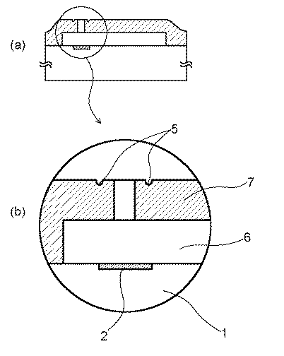
図1に、本発明の一実施形態になるインクジェットヘッドの概略断面図を示す。ここで吐出口配設部材3表面は、吐出口10の周辺に凹部5を有し、撥水性部材4が埋め込まれるように配置されている。このヘッドを長期に使用した場合、撥水性部材4の磨耗は生じるが、凹部に埋め込まれた撥水性部材は残存し(図2参照)、少なくとも吐出口周辺部は撥水性を保っておりインクに濡れることがないため印字品位の劣化を抑えることができる。
【0014】
更に、撥水性部材をフレキソ印刷等の手法で吐出口配設部材表面に転写する際に、図1のように吐出口周辺に凹部が形成されているノズルを用いると歩留まりが向上することが見出された。つまり、図12に示すように、表面がフラットに形成さたノズルに対してフレキソ印刷のような撥水性部材を溶剤に溶かして転写する方法を用いた場合には、吐出口内部に撥水性部材が入り込み、不良が発生する場合がある。
【0015】
一方、ノズル表面の吐出口周囲に凹部が形成されている場合、撥水性部材の印刷の際に凹部が液溜りとなり、吐出口内部への撥水性部材の入り込みを防ぎ、歩留まりよく安定的に生産できることが見出された。
【0016】
次に、ノズル表面の吐出口周囲に凹部を形成する方法について述べる。
【0017】
吐出口配設部材が樹脂で成形される場合、成形型に凸部形状を配置すれば可能である。また、吐出口配設部材形成後に、エキシマレーザー等で、彫り込み加工を施すことも可能である。
【0018】
しかしながら、本発明に最も適した方法は、吐出口配設部材にネガ型感光性樹脂を用い、前記感光性樹脂の限界解像度以下の線幅のマスクでパターニングすることで凹部を形成することであり、以下の利点を有する。
・吐出口パターニング時に同一マスクにより形成可能なため、吐出口とのアライメント誤差が無く、工程数の増加も無い。
・凹部の深さ方向のバラツキが極めて少ない。
・樹脂成形の際のバリや、エキシマレーザー加工の際のアブレーションによる残渣の発生等、加工残渣の発生が無い。
【0019】
通常、ネガ型感光性樹脂は、その限界解像度以下のマスクパターンに対して、基板面まで貫通しないパターンを形成する。凹部の深さ、幅等は、使用するノズル形態、及びパターニングの際の露光機により適宜決定される。
【0020】
例えば、図5に示すようなパターンを有するマスクを使用して露光、現像を行い、所望の吐出口の形成と同時に凹部が形成される。なお、同図では、吐出口形状が矩形の場合について説明しているが、吐出口形状としては、矩形のほか、円形、楕円形、多角形等所望の形状に形成することが可能である。従って、凹部も吐出口形状に合わせて形成すればよい。又、凹部は連続した溝状パターンを用いて形成しているが、撥水性部材の保持効果が得られるのであれば、連続溝としなくてもよく、例えば、等間隔で円形、矩形などの複数の凹部を形成してもよい。また、吐出口周囲に二重、三重と複数取り囲むように形成してもよい。
【0021】
このようにして形成される凹部は、吐出口端から外方に向かっての幅が1〜30μm、より好ましくは2〜10μmの範囲を有することが望ましく、また、深さとしては1〜5μm程度であることが望ましい。また、凹部は、吐出口端から20μm以内の近傍に少なくとも一つ形成されるのが望ましいが、あまり近付きすぎると撥水性部材の形成の際に撥水性部材が吐出口内に侵入したり、吐出口壁が薄くなりすぎて欠け易くなる場合もあるため、1〜5μm程度の間隔を設けることが好ましい。
【0022】
図9は、上記のインクジェットヘッドを装着して適用することのできるインクジェット記録装置の一例を示す概略斜視図である。図9において601は上記の方法で作製したインクジェットヘッドである。このヘッド601は、駆動モータ602の正逆回転に連動して駆動力伝達ギア603及び604を介して回転するリードスクリュ606の螺旋溝605に対して係合するキャリッジ607上に搭載されており、上記駆動モータ602の動力によってキャリッジ607とともにガイド608に沿って矢印a及びb方向に往復移動される。図示しない記録媒体供給装置によってプラテン609上を搬送されるプリント用紙Pの紙押さえ板610は、キャリッジ移動方向にわたってプリント用紙Pをプラテン609に対して押圧する。
【0023】
上記リードスクリュ606の一端の近傍には、フォトカプラ611及び612が配設されている。これらはキャリッジ607のレバー607aのこの域での存在を確認して駆動モータ602の回転方向切り換え等を行うためのホームポジション検知手段である。図において613は上述のインクジェットヘッド601の吐出口のある前面を覆うキャップ部材614を支持する支持部材である。又、615はキャップ部材614の内部にヘッド601から空吐出等されて溜まったインクを吸引するインク吸引手段である。この吸引手段615によりキャップ内開口部616を介してヘッド601の吸引回復が行われる。617はクリーニングブレードであり、618はブレード617を前後方向(上記キャリッジ607の移動方向に直交する方向)に移動可能にする移動部材であり、ブレード617及び移動部材618は本体支持体619に支持されている。上記ブレード617はこの形態に限らず、他の周知のクリーニングブレードであってもよい。620は吸引回復操作にあたって、吸引を開始するためのレバーであり、キャリッジ607と係合するカム621の移動に伴って移動し、駆動モータ602からの駆動カがクラッチ切り換え等の公知の伝達手段で移動制御される。上記ヘッド601に設けられたインク吐出圧力発生素子2に信号を付与したり、前述した各機構の駆動制御を司ったりするインクジェット制御部は装置本体側に設けられており、ここには図示しない。
【0024】
上述の構成を有するインクジェット記録装置600は、図示しない被記録材給送装置によりプラテン609上を搬送される被記録材Pに対し、ヘッド601は用紙Pの全幅にわたって往復移動しながら記録を行う。
【0025】
なお、本発明は、インクジェット記録方式の中でも、インク吐出を行わせるために利用されるエネルギーとして熱エネルギーを発生する手段(例えば、電気熱変換体やレーザ光等)を備え、前記熱エネルギーによりインクの状態変化を生起させる方式の記録ヘッド、記録装置において優れた効果をもたらすものである。かかる方式によれば、記録の高密度化、高精細化が達成できるからである。
【0026】
その代表的な構成や原理については、例えば、米国特許第4,723,129号及び同第4,740,796号に開示されている基本的な原理を用いて行うものが望ましい。この方式は所謂オンデマンド型、コンティニュアス型のいずれにも適用可能であるが、特に、オンデマンド型の場合には、液体(インク)が保持されているシートや液路に対応して配置されている電気熱変換体に、記録情報に対応していて核沸騰を越える急速な温度上昇を与える少なくとも1つの駆動信号を印加することによって、結果的にこの駆動信号に一対一で対応した液体(インク)内の気泡を形成できるので有効である。この気泡の成長、収縮により吐出用開口を介して液体(インク)を吐出させて、少なくとも1つの滴を形成する。この駆動信号をパルス形状とすると、即時適切に気泡の成長収縮が行われるので、特に応答性に優れた液体(インク)の吐出が達成でき、より好ましい。このパルス形状の駆動信号としては、米国特許第4,463,359号、同第4,345,262号に記載されているようなものが適している。尚、上記熱作用面の温度上昇率に関する発明の米国特許第4,313,124号に記載されている条件を採用すると、さらに優れた記録を行うことができる。
【0027】
記録ヘッドの構成としては、上述の各明細書に開示されているような吐出口、液路、電気熱変換体の組み合わせ構成(直線状液流路または直角液流路)の他に熱作用部が屈曲する領域に配置されている構成を開示する米国特許第4,558,333号、同第4,4459,600号を用いた構成も本発明に含まれるものである。加えて、複数の電気熱変換体に対して、共通するスリットを電気熱変換体の吐出部とする構成を開示する特開昭59−123670号公報や熱エネルギーの圧力波を吸収する開孔を吐出部に対応させる構成を開示する特開昭59−138461号公報に基づいた構成としても本発明の効果は有効である。即ち、記録ヘッドの形態がどのようなものであっても、本発明によれば記録を確実に効率よく行うことができるようになるからである。
【0028】
さらに、記録装置が記録できる記録媒体の最大幅に対応した長さを有するフルラインタイプの記録ヘッドに対しても本発明は有効に適用できる。そのような記録ヘッドとしては、複数記録ヘッドの組み合わせによってその長さを満たす構成や、一体的に形成された1個の記録ヘッドとしての構成のいずれかでもよい。
【0029】
又、本発明の記録装置の構成として、記録ヘッドの吐出回復手段、予備的な補助手段等を付加することは本発明の効果を一層安定できるので、好ましいものである。これらを具体的に挙げれば、記録ヘッドに対してのキャッピング手段、クリーニング手段、加圧或いは吸引手段、電気熱変換体或いはこれとは別の加熱素子或いはこれらの組み合わせを用いて加熱を行う予備加熱手段、記録とは別の吐出を行う予備吐出手段を挙げることができる。
【0030】
又、搭載される記録ヘッドの種類ないし個数についても、例えば単色のインクに対応して1個のみが設けられたものの他、記録色や濃度を異にする複数のインクに対応して複数個数設けられるものであってもよい。即ち、例えば記録ヘッドを一体的に構成するか複数個の組み合わせによるかいずれのでもよいが、異なる色の複色カラー、または混色によるフルカラーの各記録モードの少なくとも一つを備えた装置にも本発明が極めて有効である。
【0031】
更に加えて、以上説明した本発明においては、インクを液体として説明しているが、室温やそれ以下で固化するインクであっても、室温以上で軟化もしくは液化するものを用いてもよく、或いはインクジェット方式ではインク自体を30℃以上70℃以下の範囲内で温度調整を行ってインクの粘性を安定吐出範囲にあるように温度制御するものが一般的であるから、使用記録信号付与時にインクが液状をなすものを用いてもよい。加えて、熱エネルギーによる昇温を、インクの固形状態から液体状態への状態変化のエネルギーとして使用せしめることで積極的に防止するため、またはインクの蒸発を防止するため、放置状態で固化し加熱によって液化するインクを用いてもよい。いずれにしても、熱エネルギーの記録信号に応じた付与によってインクが液化し、液状インクが吐出されるものや、記録媒体に到達する時点ではすでに固化し始めるもの等のような、熱エネルギーの付与によって初めて液化する性質のインクを使用する場合も本発明は適用可能である。このような場合のインクは、特開昭54−56847号公報或いは特開昭60−71260号公報に記載されるような、多孔質シート凹部または貫通孔に液状又は固形物として保持された状態で、電気熱変換体に対して対向するような形態としてもよい。本発明において、上述した各インクに対して最も有効なものは、上述した膜沸騰方式を実行したものである。
【0032】
更に加えて、本発明のインクジェット記録装置の形態としては、コンピューター等の情報処理機器の画像出力端末として用いられるものの他、リーダ等の組み合わせた複写装置、更には送受信機能を有するファクシミリ装置の形態を採るもの等であってもよい。
【0033】
【実施例】
以下、実施例により本発明を具体的に説明するが、本発明はこれらの実施例のみに限定されるものではない。
【0034】
実施例1
まず、以下に示す方法でインクジェットヘッドを作成した。
【0035】
図3に示すように、Siウェハー基板1上にインクを吐出するために利用されるエネルギーを発生するエネルギー発生素子として電気熱変換素子(TaN)2を形成した。尚、電気熱変換素子2にはその素子を動作させるための制御信号入力電極が接続されている(図示せず)。この、このA−A’断面が図4(a)である。
【0036】
次いで図4(b)に示すように、基板1上に東京応化工業(株)ポジレジスト「ODUR」からなるインク流路パターン6を形成した(厚みt1=12μm)。
【0037】
更に下記第1表に記載のネガ型感光性樹脂層7を適宜塗布溶媒に溶解し、スピンコートにより基板1上に形成した。尚、樹脂層7の厚みは前記「ODUR」上でt2=10μmに形成されている(図4(c))。
【0038】
【表1】
ここで、吐出口及び凹部形成マスク8を介してキヤノン製マスクアライナー「MPA600 super」を用いて、露光量1.0J/cm2で露光を行った(図4(d))。尚、吐出口部はマスク寸法a=24μm角、凹部形成マスクは線幅b=3μm、吐出口と凹部との間隔c=1μmの図5(吐出口部の上面図)に示すマスクを用いた。次いでホットプレートで90℃で4分間加熱し、メチルイソブチルケトン(MIBK)/キシレン=2/3で現像してインク流路パターン6を除去し、キシレンでリンスを行い、吐出口及び凹部を形成した(図6)。吐出口は、22.8μm角に、凹部は幅2μm(ノズル表面)、深さ2μmに形成された(図6(b))。吐出口端から凹部までの間隔は、1.2μmであった。
【0040】
次いで、下記第2表に記載のネガ型感光性撥水性部材4を適宜塗布溶媒に溶解し、吐出口配設部材7上にスピンコートで形成し(膜厚1μm)、吐出口配設部材と同様にパターニングを行った。
【0041】
【表2】
撥水性部材4は、吐出口周辺の凹部に埋め込まれるように配置される。なお、撥水性部材4は、吐出口角(W1)に対して周辺に23μm角(W2)の領域を残すように形成される(図7参照)。
【0043】
次いで、前記基板1をSi異方性エッチングにより図8に示すようにエッチングしてインク供給口9を形成し、インク流路パターン6を除去し、更に吐出口配設部材、撥水性部材を完全に硬化させるために180℃で1時間加熱を行いインクジェットヘッドを得た。
【0044】
又、比較のため、吐出口周囲に凹部5を形成していない吐出口配設部材上に同様の方法により撥水性部材を形成し、以下同様の工程で形成したインクジェットヘッドも試作した。
【0045】
これらのインクジェットヘッドに、インクを充填し、長期の使用を想定してブレードによるワイピングを5000回行った後に、印字試験を実施した。その結果、凹部5を形成した本発明のインクジェットヘッドでは、良好な印字品位が維持されていた。一方、凹部を形成せずに作製したインクジェットヘッドでは、インク液滴の吐出方向のヨレに起因すると思われる印字品位の劣化が認められるヘッドがあった。
【0046】
そこで、印字品位の劣化したインクジェットヘッドのノズル表面を観察したところ、撥水性部材が一部欠落しており、その部分がインクに濡れた状態となっていた。同時に、凹部を有する本発明のインクジェットヘッドのノズル表面を観察したところ、吐出口周辺の凹部に埋め込まれるように配置された撥水性部材はすべて残存しており、十分な撥水性が維持できていることから、インクで濡れてはいなかった。
【0047】
以上、本実施例からわかるように、ノズル吐出口周辺に凹部を設け、該凹部に撥水性部材を埋め込むように配置することで、ブレードによるワイピング耐性の高い、すなわち、長期の使用に際して印字品位の劣化の少ないインクジェットヘッドを提供することが可能となる。
【0048】
実施例2
本実施例では、撥水性部材としてパーフルオロカーボンを主鎖に持つ高分子化合物(旭硝子社製、商品名「サイトップ」)を適宜溶媒に溶解し、フレキソ印刷でノズル表面に転写させる方法について説明する。
【0049】
実施例1と同様にして凹部5を有するノズルを形成し、次いで、「サイトップ」/フッ素系シランカップリング材「KP802」(信越化学製)=100/5をCTsolve 100溶媒に溶解し、フレキソ印刷機でノズル表面に撥水性部材を1μm厚となるように形成した。150℃で2時間加熱することで溶媒を乾燥させ、撥水性部材をノズル表面に固着した。また比較のため、凹部5を設けずにフレキソ印刷により撥水性部材を形成したインクジェットヘッドも試作した。
【0050】
こうして得られたインクジェットヘッドに対して、実施例1と同様に印字し件を実施したところ、凹部を有する本発明のインクジェットヘッドでは、歩留まりが92%であったのに対し、凹部を形成せずにフレキソ印刷を実施したヘッドの歩留まりは63%であった。凹部のないヘッドの不良解析を行ったところ、ノズル内に撥水性部材が進入して印字不良を引き起こしていることが確認された。一方、凹部を有する本発明のヘッドの不良解析では、撥水性部材のノズル内への進入は見つからず、ごみ等の他の要因に起因することが判明した。
【0051】
これは、撥水性部材の印刷の際に凹部が液溜りとなり、吐出口内部への撥水性部材の進入が防止されたためと考えられる。
【0052】
又、凹部を有するヘッドの良品を実施例1と同様にブレードによるワイピングを5000回行った後、印字試験を行ったところ、良好な印字品位が維持されていた。
【0053】
【発明の効果】
本発明によれば、
・長期の使用に際しても撥水性部材が凹部に入って吐出口配設部材に確実に固定され残るので、印字品位の劣化の少ないヘッドを提供することが可能となる。
・吐出口内部への撥水性部材の進入が防止され、高歩留まりで高品位の印字が可能となるインクジェットヘッドを生産することが可能となる。
【図面の簡単な説明】
【図1】本発明のインクジェットヘッドの吐出口周辺の部分断面図である。
【図2】本発明にかかるインクジェットヘッドを長期に使用した後の、磨耗した撥水性部材の状態を示す部分断面図である。
【図3】本発明のインクジェットヘッドの製造方法を説明するための図で、基板上にインク吐出圧発生素子が形成されている状態を示す概略斜視図である。
【図4】(a)〜(d)は、本発明のインクジェットヘッドの製造方法を説明するための概略断面図である。
【図5】図4(d)で使用するマスクの、吐出口及び凹部のパターンを説明する図である。
【図6】本発明のインクジェットヘッドの製造方法を説明するための図で、吐出口配設部材を露光、現像した後の概略断面図であり、(b)はその部分拡大図である。
【図7】本発明のインクジェットヘッドの製造方法を説明するための図で、撥水性部材4を塗布した状態を示す図である。
【図8】完成した本発明のインクジェットヘッドの模式的断面図である。
【図9】本発明に係るインクジェットヘッドを装着して適用することのできるインクジェット記録装置の一例を示す概略斜視図である。
【図10】従来技術によるインクジェットヘッドの模式的部分断面図である。
【図11】従来技術による課題を説明するための概略断面図である。
【図12】従来例のフレキソ印刷による課題を説明するための概略断面図である。
【符号の説明】
1 基板
2 インク吐出エネルギー発生素子
3 吐出口配設部材
4 撥水性部材
5 凹部
10 吐出口[0001]
BACKGROUND OF THE INVENTION
The present invention relates to a method for producing an ink-jet heads for generating an ink droplet used in ink jet recording. In particular, the present invention relates to a method for high yield production of inkjet heads less deterioration of print quality with respect to long-term use.
[0002]
[Prior art]
Conventionally, various proposals have been made for the surface treatment of the ejection port surface of an inkjet head. Most of them are related to water repellent treatment, i.e., by applying water repellent treatment to the surface of the discharge port to reduce the wettability of the surface of the discharge port with respect to ink, The purpose is to perform high-quality printing.
[0003]
However, the durability / durability of the effect of the water repellent treatment is not sufficient. That is, since the surface of the head is wiped with a blade member at the time of cleaning the ink-jet head or the like, deterioration in print quality due to wear of the water-repellent member was recognized.
[0004]
Further, when the water repellent treatment is performed after the discharge port is formed, if even a part of the water-repellent member enters the discharge port, printing failure occurs, and the productivity of the conventional method is not high.
[0005]
FIG. 10 is a cross-sectional view of a nozzle portion of a conventional inkjet head, in which an ejection
[0006]
Of course, if the water-repellent member is set thick in advance, the wear resistance is improved, but the water-repellent member is made of a material having a small surface tension, and it is difficult to increase the film thickness.
[0007]
Further, it is possible to thicken the water repellent member by a technique such as Ni eutectoid plating containing Teflon particles, but the discharge port arrangement member is limited to metal for forming the water repellent member by plating, etc. There are large restrictions.
[0008]
[Problems to be solved by the invention]
The present invention has been made in view of the above-described points, and a recess is formed in a part of the surface of the discharge port arrangement member where the ink discharge port is formed, and the water repellent member is disposed in the recess. When providing water-repellent treatment after forming the discharge port when providing a highly durable ink-jet head, it is possible to produce a highly productive ink-jet head with very little water repellent material entering the discharge port. It also provides a method.
[0010]
[Means for Solving the Problems]
The present invention that achieves the above object includes a step of forming an energy generating element that generates energy used for discharging ink on a substrate, and an outlet that is provided with an outlet for discharging ink on the substrate. A step of arranging the disposing member, a step of forming a discharge port in the discharge port disposing member, and forming at least one recess in the vicinity of the discharge port of the surface of the discharge port disposing member on which the discharge port is disposed. And a step of disposing a water-repellent member on the surface including the concave portion, wherein the discharge port disposing member is formed of a negative photosensitive resin and is less than a limit resolution of the negative photosensitive resin. An ink jet head comprising: a step of forming the recess not penetrating to the surface of the substrate by pattern transfer, and the step of forming the discharge port and the step of forming the recess using the same mask. It is achieved by the manufacturing method.
[0012]
DETAILED DESCRIPTION OF THE INVENTION
The present invention is described in detail below.
[0013]
FIG. 1 is a schematic sectional view of an ink jet head according to an embodiment of the present invention. Here, the surface of the discharge
[0014]
Furthermore, when transferring the water-repellent member to the surface of the discharge port arrangement member by a method such as flexographic printing, it is seen that the yield is improved by using a nozzle having a recess formed around the discharge port as shown in FIG. It was issued. That is, as shown in FIG. 12, when a method of transferring a water-repellent member such as flexographic printing in a solvent to a nozzle having a flat surface is used, the water-repellent member is placed inside the discharge port. May enter and cause defects.
[0015]
On the other hand, when a recess is formed around the discharge port on the nozzle surface, the recess becomes a liquid pool during printing of the water-repellent member, preventing entry of the water-repellent member into the discharge port, and stable production with high yield. It was found that it was possible.
[0016]
Next, a method for forming a recess around the discharge port on the nozzle surface will be described.
[0017]
When the discharge port arrangement member is molded from resin, it is possible if the convex shape is arranged in the mold. Further, engraving can be performed with an excimer laser or the like after the discharge port arrangement member is formed.
[0018]
However, the most suitable method for the present invention is to form a recess by using a negative photosensitive resin for the discharge port arrangement member and patterning with a mask having a line width equal to or lower than the limit resolution of the photosensitive resin. Has the following advantages.
-Since it can be formed with the same mask at the time of discharge port patterning, there is no alignment error with the discharge port, and there is no increase in the number of processes.
・ There is very little variation in the depth direction of the recess.
・ No generation of processing residues such as burrs during resin molding and generation of residues due to ablation during excimer laser processing.
[0019]
Usually, the negative photosensitive resin forms a pattern that does not penetrate to the substrate surface with respect to a mask pattern having a resolution lower than that. The depth, width, and the like of the recess are appropriately determined depending on the form of the nozzle used and the exposure machine used for patterning.
[0020]
For example, exposure and development are performed using a mask having a pattern as shown in FIG. 5, and a recess is formed simultaneously with the formation of a desired discharge port. In addition, although the figure demonstrates the case where the discharge port shape is a rectangle, as a discharge port shape, it is possible to form in desired shapes, such as circular, an ellipse, and a polygon other than a rectangle. Accordingly, the recess may be formed in accordance with the shape of the discharge port. In addition, the concave portion is formed using a continuous groove-shaped pattern. However, as long as the retention effect of the water-repellent member can be obtained, the concave portion may not be a continuous groove, for example, a plurality of circular, rectangular, etc. at equal intervals. A recess may be formed. Further, it may be formed so as to surround a plurality of double and triple around the discharge port.
[0021]
The recess formed in this manner desirably has a width from the discharge port end to the outside of 1 to 30 μm, more preferably 2 to 10 μm, and the depth is about 1 to 5 μm. It is desirable that In addition, it is desirable that at least one recess is formed in the vicinity of within 20 μm from the end of the discharge port. However, if it is too close, the water-repellent member may enter the discharge port when forming the water-repellent member, Since the wall may become too thin and easily chipped, it is preferable to provide an interval of about 1 to 5 μm.
[0022]
FIG. 9 is a schematic perspective view showing an example of an ink jet recording apparatus to which the above ink jet head can be attached and applied. In FIG. 9,
[0023]
[0024]
The ink
[0025]
The present invention includes means (for example, an electrothermal converter, a laser beam, etc.) that generates thermal energy as energy used for performing ink ejection among the ink jet recording methods, and the ink is generated by the thermal energy. In the recording head and the recording apparatus of the type that causes the state change, excellent effects are brought about. This is because such a system can achieve higher recording density and higher definition.
[0026]
As its typical configuration and principle, for example, it is desirable to use the basic principle disclosed in US Pat. Nos. 4,723,129 and 4,740,796. This method can be applied to both the so-called on-demand type and continuous type. In particular, in the case of the on-demand type, it is arranged corresponding to the sheet or liquid path holding the liquid (ink). By applying at least one drive signal corresponding to the recorded information and applying a rapid temperature rise exceeding the nucleate boiling to the electrothermal transducer, the liquid corresponding to this drive signal on a one-to-one basis. This is effective because air bubbles in (ink) can be formed. By the growth and contraction of the bubbles, liquid (ink) is ejected through the ejection opening to form at least one droplet. It is more preferable that the drive signal has a pulse shape, since the bubble growth and contraction is performed immediately and appropriately, and thus it is possible to achieve discharge of a liquid (ink) having particularly excellent responsiveness. As this pulse-shaped drive signal, those described in US Pat. Nos. 4,463,359 and 4,345,262 are suitable. Further excellent recording can be performed by using the conditions described in US Pat. No. 4,313,124 of the invention relating to the temperature rise rate of the heat acting surface.
[0027]
As the configuration of the recording head, in addition to the combination configuration (straight liquid channel or right-angle liquid channel) of the discharge port, the liquid channel, and the electrothermal transducer as disclosed in each of the above-mentioned specifications, the heat acting part A configuration using US Pat. Nos. 4,558,333 and 4,4459,600, which disclose a configuration in which the lens is disposed in the bent region, is also included in the present invention. In addition, for a plurality of electrothermal transducers, Japanese Patent Application Laid-Open No. 59-123670 that discloses a configuration in which a common slit is used as a discharge portion of the electrothermal transducer, or an aperture that absorbs pressure waves of thermal energy is provided. The effect of the present invention is also effective as a configuration based on Japanese Patent Application Laid-Open No. 59-138461 which discloses a configuration corresponding to the discharge unit. That is, regardless of the form of the recording head, according to the present invention, recording can be performed reliably and efficiently.
[0028]
Furthermore, the present invention can be effectively applied to a full-line type recording head having a length corresponding to the maximum width of a recording medium that can be recorded by the recording apparatus. As such a recording head, either a configuration satisfying the length by a combination of a plurality of recording heads or a configuration as a single recording head formed integrally may be used.
[0029]
In addition, it is preferable to add a recording head ejection recovery means, a preliminary auxiliary means, etc. as the configuration of the recording apparatus of the present invention, since the effects of the present invention can be further stabilized. Specifically, preheating is performed by using a capping unit, a cleaning unit, a pressurizing or suction unit, an electrothermal converter, a heating element different from this, or a combination thereof. Examples thereof include preliminary discharge means for performing discharge different from the means and recording.
[0030]
Also, regarding the type or number of recording heads to be mounted, for example, a plurality of recording heads are provided corresponding to a plurality of inks having different recording colors and densities, in addition to those having only one corresponding to a single color ink. May be used. That is, for example, the recording head may be formed integrally or by a combination of a plurality of recording heads. However, the present invention is also applicable to an apparatus having at least one recording mode of multiple colors of different colors or mixed colors. The invention is extremely effective.
[0031]
In addition, in the present invention described above, the ink is described as a liquid. However, an ink that solidifies at room temperature or lower, a softened or liquefied ink at room temperature or higher, or may be used. In the ink jet method, the temperature of the ink itself is generally adjusted within a range of 30 ° C. or higher and 70 ° C. or lower to control the temperature of the ink so that it is in the stable discharge range. A liquid material may be used. In addition, it is solidified and heated in an untreated state in order to actively prevent the temperature rise caused by thermal energy from being used as energy for changing the state of the ink from the solid state to the liquid state, or to prevent ink evaporation. You may use the ink which liquefies by. In any case, application of thermal energy, such as ink that liquefies by application of thermal energy according to a recording signal and liquid ink is ejected, or that already starts to solidify when reaching the recording medium. The present invention can also be applied to the case where ink having the property of being liquefied for the first time is used. The ink in such a case is in a state of being held as a liquid or a solid in a porous sheet recess or through-hole as described in JP-A-54-56847 or JP-A-60-71260. Alternatively, the electrothermal converter may be opposed to the electrothermal converter. In the present invention, the most effective one for each of the inks described above is the one obtained by executing the film boiling method described above.
[0032]
In addition, the ink jet recording apparatus of the present invention may be used as an image output terminal of information processing equipment such as a computer, a copying apparatus combined with a reader, or a facsimile apparatus having a transmission / reception function. It may be one taken.
[0033]
【Example】
EXAMPLES Hereinafter, although an Example demonstrates this invention concretely, this invention is not limited only to these Examples.
[0034]
Example 1
First, an ink jet head was prepared by the following method.
[0035]
As shown in FIG. 3, an electrothermal conversion element (TaN) 2 was formed on the
[0036]
Next, as shown in FIG. 4B, an ink
[0037]
Furthermore, the negative
[0038]
[Table 1]
Here, exposure was performed at an exposure amount of 1.0 J / cm 2 using a Canon mask aligner “MPA600 super” through the discharge port and the recess formation mask 8 (FIG. 4D). Note that the mask shown in FIG. 5 (top view of the discharge port portion) having a mask size a = 24 μm square for the discharge port portion, a line width b = 3 μm for the recess formation mask, and a distance c = 1 μm between the discharge port and the recess portion was used. . Next, it was heated at 90 ° C. for 4 minutes on a hot plate, developed with methyl isobutyl ketone (MIBK) / xylene = 2/3 to remove the ink
[0040]
Next, the negative photosensitive water-
[0041]
[Table 2]
The
[0043]
Next, the
[0044]
For comparison, a water-repellent member was formed by a similar method on a discharge port arrangement member that does not have a
[0045]
These ink jet heads were filled with ink, and wiping with a blade was performed 5000 times assuming long-term use, and then a printing test was performed. As a result, in the ink jet head of the present invention in which the
[0046]
Accordingly, when the nozzle surface of the inkjet head having deteriorated print quality was observed, a part of the water-repellent member was missing and the part was wet with ink. At the same time, when the nozzle surface of the inkjet head of the present invention having a recess was observed, all the water-repellent members arranged so as to be embedded in the recess around the discharge port remained, and sufficient water repellency was maintained. Therefore, it was not wet with ink.
[0047]
As described above, as can be seen from this embodiment, by providing a recess around the nozzle discharge port and embedding the water-repellent member in the recess, the wiping resistance by the blade is high, that is, the print quality is improved when used for a long time. It is possible to provide an inkjet head with little deterioration.
[0048]
Example 2
In this example, a method of dissolving a polymer compound having a perfluorocarbon main chain as a water-repellent member (manufactured by Asahi Glass Co., Ltd., trade name “Cytop”) in a suitable solvent and transferring it to the nozzle surface by flexographic printing will be described. .
[0049]
A nozzle having a
[0050]
The ink jet head thus obtained was printed in the same manner as in Example 1. As a result, the yield of the ink jet head according to the present invention having a concave portion was 92%, but no concave portion was formed. The yield of the head subjected to flexographic printing was 63%. When a defect analysis of a head without a concave portion was performed, it was confirmed that a water-repellent member entered the nozzle and caused a printing defect. On the other hand, in the failure analysis of the head of the present invention having the concave portion, it was found that the water repellent member did not enter the nozzle and was caused by other factors such as dust.
[0051]
This is presumably because the concave portion became a liquid pool during printing of the water repellent member, and the water repellent member was prevented from entering the inside of the discharge port.
[0052]
Further, when a good product having a concave portion was wiped 5000 times with a blade in the same manner as in Example 1 and then subjected to a print test, good print quality was maintained.
[0053]
【The invention's effect】
According to the present invention,
Since the water-repellent member enters the recess and remains securely fixed to the discharge port arrangement member even during long-term use, it is possible to provide a head with little deterioration in print quality.
-It is possible to produce an ink jet head that prevents the water-repellent member from entering the discharge port and enables high-quality printing with a high yield.
[Brief description of the drawings]
FIG. 1 is a partial cross-sectional view around a discharge port of an ink jet head of the present invention.
FIG. 2 is a partial cross-sectional view showing a state of a worn water-repellent member after the inkjet head according to the present invention has been used for a long period of time.
FIG. 3 is a schematic perspective view showing a state in which an ink discharge pressure generating element is formed on a substrate for explaining a method of manufacturing an ink jet head of the present invention.
FIGS. 4A to 4D are schematic cross-sectional views for explaining a method of manufacturing an ink jet head according to the present invention.
FIG. 5 is a diagram illustrating a pattern of ejection openings and recesses of a mask used in FIG.
FIG. 6 is a view for explaining the method of manufacturing an ink jet head of the present invention, and is a schematic cross-sectional view after exposing and developing a discharge port arrangement member, and (b) is a partially enlarged view thereof.
FIG. 7 is a view for explaining a method of manufacturing an ink jet head according to the present invention, and shows a state in which a
FIG. 8 is a schematic cross-sectional view of the completed inkjet head of the present invention.
FIG. 9 is a schematic perspective view showing an example of an ink jet recording apparatus to which the ink jet head according to the present invention can be attached and applied.
FIG. 10 is a schematic partial cross-sectional view of an inkjet head according to a conventional technique.
FIG. 11 is a schematic cross-sectional view for explaining a problem according to the prior art.
FIG. 12 is a schematic cross-sectional view for explaining a problem due to flexographic printing of a conventional example.
[Explanation of symbols]
DESCRIPTION OF
Claims (5)
Priority Applications (1)
| Application Number | Priority Date | Filing Date | Title |
|---|---|---|---|
| JP36104197A JP3610215B2 (en) | 1997-12-26 | 1997-12-26 | Inkjet head manufacturing method |
Applications Claiming Priority (1)
| Application Number | Priority Date | Filing Date | Title |
|---|---|---|---|
| JP36104197A JP3610215B2 (en) | 1997-12-26 | 1997-12-26 | Inkjet head manufacturing method |
Publications (2)
| Publication Number | Publication Date |
|---|---|
| JPH11188881A JPH11188881A (en) | 1999-07-13 |
| JP3610215B2 true JP3610215B2 (en) | 2005-01-12 |
Family
ID=18471947
Family Applications (1)
| Application Number | Title | Priority Date | Filing Date |
|---|---|---|---|
| JP36104197A Expired - Fee Related JP3610215B2 (en) | 1997-12-26 | 1997-12-26 | Inkjet head manufacturing method |
Country Status (1)
| Country | Link |
|---|---|
| JP (1) | JP3610215B2 (en) |
Families Citing this family (2)
| Publication number | Priority date | Publication date | Assignee | Title |
|---|---|---|---|---|
| US8220901B2 (en) * | 2009-06-16 | 2012-07-17 | Canon Kabushiki Kaisha | Liquid discharge head and manufacturing method thereof |
| JP6388385B2 (en) * | 2014-08-20 | 2018-09-12 | キヤノン株式会社 | Liquid discharge head and method of manufacturing liquid discharge head |
-
1997
- 1997-12-26 JP JP36104197A patent/JP3610215B2/en not_active Expired - Fee Related
Also Published As
| Publication number | Publication date |
|---|---|
| JPH11188881A (en) | 1999-07-13 |
Similar Documents
| Publication | Publication Date | Title |
|---|---|---|
| CN100425447C (en) | Liquid ejection head, liquid ejection apparatus, and method for fabricating liquid ejection head | |
| US5524784A (en) | Method for producing ink jet head by multiple development of photosensitive resin, ink jet head produced thereby, and ink jet apparatus with the ink jet head | |
| CN1145305A (en) | Manufacturing method of ink jet head | |
| US6186616B1 (en) | Ink jet head having an improved orifice plate, a method for manufacturing such ink jet heads, and an ink jet apparatus provided with such ink jet head | |
| JP2003300323A (en) | Ink jet head and method of manufacturing the same | |
| JP2001038917A (en) | Inkjet printer | |
| JP2012020470A (en) | Liquid ejection head, and method of manufacturing the same | |
| US8622516B2 (en) | Ink jet recording head and method of producing ink jet recording head | |
| JP5586978B2 (en) | Method for manufacturing liquid discharge head | |
| JP4374811B2 (en) | Method for manufacturing nozzle plate for inkjet printer | |
| JP3610215B2 (en) | Inkjet head manufacturing method | |
| JP3095795B2 (en) | Ink jet recording head and method of manufacturing the head | |
| JP4164321B2 (en) | Ink jet recording head manufacturing method, ink jet recording head, and ink jet recording apparatus | |
| JPH08142327A (en) | Inkjet recording device recording head | |
| JP4671330B2 (en) | Method for manufacturing ink jet recording head | |
| JP2003089209A (en) | Method for manufacturing liquid discharge head and liquid discharge head | |
| JP2006082329A (en) | Method for manufacturing ink jet recording head | |
| JPH07164639A (en) | INKJET PRINT HEAD, MANUFACTURING METHOD THEREOF, AND PRINTING DEVICE INCLUDING THE PRINT HEAD | |
| JP2007055007A (en) | Ink jet recording head and manufacturing method thereof | |
| JPH0524205A (en) | Ink jet recording head and manufacturing method thereof | |
| JP3025119B2 (en) | Method for manufacturing liquid jet recording head | |
| JPH08118655A (en) | Inkjet nozzle plate | |
| JPH07156403A (en) | Ink jet recording head and manufacturing method | |
| JPH07178914A (en) | Inkjet head and manufacturing method thereof | |
| JP2004306456A (en) | Method of manufacturing liquid jet recording head, liquid jet recording head manufactured by the method, surface-treated liquid jet recording head, and recording apparatus including the liquid jet recording head |
Legal Events
| Date | Code | Title | Description |
|---|---|---|---|
| A131 | Notification of reasons for refusal |
Free format text: JAPANESE INTERMEDIATE CODE: A131 Effective date: 20040218 |
|
| A521 | Written amendment |
Free format text: JAPANESE INTERMEDIATE CODE: A523 Effective date: 20040419 |
|
| RD03 | Notification of appointment of power of attorney |
Free format text: JAPANESE INTERMEDIATE CODE: A7423 Effective date: 20040419 |
|
| TRDD | Decision of grant or rejection written | ||
| A01 | Written decision to grant a patent or to grant a registration (utility model) |
Effective date: 20041006 Free format text: JAPANESE INTERMEDIATE CODE: A01 |
|
| A61 | First payment of annual fees (during grant procedure) |
Effective date: 20041018 Free format text: JAPANESE INTERMEDIATE CODE: A61 |
|
| R150 | Certificate of patent (=grant) or registration of utility model |
Free format text: JAPANESE INTERMEDIATE CODE: R150 |
|
| FPAY | Renewal fee payment (prs date is renewal date of database) |
Free format text: PAYMENT UNTIL: 20071022 Year of fee payment: 3 |
|
| FPAY | Renewal fee payment (prs date is renewal date of database) |
Free format text: PAYMENT UNTIL: 20081022 Year of fee payment: 4 |
|
| FPAY | Renewal fee payment (prs date is renewal date of database) |
Year of fee payment: 5 Free format text: PAYMENT UNTIL: 20091022 |
|
| FPAY | Renewal fee payment (prs date is renewal date of database) |
Free format text: PAYMENT UNTIL: 20091022 Year of fee payment: 5 |
|
| FPAY | Renewal fee payment (prs date is renewal date of database) |
Year of fee payment: 6 Free format text: PAYMENT UNTIL: 20101022 |
|
| FPAY | Renewal fee payment (prs date is renewal date of database) |
Free format text: PAYMENT UNTIL: 20101022 Year of fee payment: 6 |
|
| FPAY | Renewal fee payment (prs date is renewal date of database) |
Free format text: PAYMENT UNTIL: 20111022 Year of fee payment: 7 |
|
| LAPS | Cancellation because of no payment of annual fees |