JP3607987B2 - Exhaust gas purification device for internal combustion engine - Google Patents
Exhaust gas purification device for internal combustion engine Download PDFInfo
- Publication number
- JP3607987B2 JP3607987B2 JP2001096796A JP2001096796A JP3607987B2 JP 3607987 B2 JP3607987 B2 JP 3607987B2 JP 2001096796 A JP2001096796 A JP 2001096796A JP 2001096796 A JP2001096796 A JP 2001096796A JP 3607987 B2 JP3607987 B2 JP 3607987B2
- Authority
- JP
- Japan
- Prior art keywords
- particulate filter
- exhaust
- chamber
- particulates
- amount
- Prior art date
- Legal status (The legal status is an assumption and is not a legal conclusion. Google has not performed a legal analysis and makes no representation as to the accuracy of the status listed.)
- Expired - Fee Related
Links
- 238000002485 combustion reaction Methods 0.000 title claims description 108
- 238000000746 purification Methods 0.000 title claims description 27
- 239000007789 gas Substances 0.000 claims description 150
- 229910052760 oxygen Inorganic materials 0.000 claims description 148
- QVGXLLKOCUKJST-UHFFFAOYSA-N atomic oxygen Chemical compound [O] QVGXLLKOCUKJST-UHFFFAOYSA-N 0.000 claims description 147
- 239000001301 oxygen Substances 0.000 claims description 147
- 239000003054 catalyst Substances 0.000 claims description 66
- 239000003795 chemical substances by application Substances 0.000 claims description 62
- 238000007254 oxidation reaction Methods 0.000 claims description 39
- 230000003647 oxidation Effects 0.000 claims description 38
- 238000011144 upstream manufacturing Methods 0.000 claims description 38
- 230000001590 oxidative effect Effects 0.000 claims description 5
- 230000000717 retained effect Effects 0.000 claims description 5
- 230000003197 catalytic effect Effects 0.000 claims description 2
- 239000000446 fuel Substances 0.000 description 171
- BASFCYQUMIYNBI-UHFFFAOYSA-N platinum Chemical group [Pt] BASFCYQUMIYNBI-UHFFFAOYSA-N 0.000 description 61
- 239000004071 soot Substances 0.000 description 50
- 238000002347 injection Methods 0.000 description 28
- 239000007924 injection Substances 0.000 description 28
- 238000005192 partition Methods 0.000 description 27
- 229910052697 platinum Inorganic materials 0.000 description 20
- 230000002829 reductive effect Effects 0.000 description 18
- 239000000779 smoke Substances 0.000 description 17
- 230000007423 decrease Effects 0.000 description 16
- 239000011261 inert gas Substances 0.000 description 16
- 239000010419 fine particle Substances 0.000 description 15
- 238000010586 diagram Methods 0.000 description 14
- 239000011148 porous material Substances 0.000 description 14
- 229910002089 NOx Inorganic materials 0.000 description 13
- 229930195733 hydrocarbon Natural products 0.000 description 13
- 150000002430 hydrocarbons Chemical class 0.000 description 13
- 239000011575 calcium Substances 0.000 description 12
- 229910052700 potassium Inorganic materials 0.000 description 12
- FGIUAXJPYTZDNR-UHFFFAOYSA-N potassium nitrate Chemical compound [K+].[O-][N+]([O-])=O FGIUAXJPYTZDNR-UHFFFAOYSA-N 0.000 description 12
- 239000000126 substance Substances 0.000 description 12
- ZLMJMSJWJFRBEC-UHFFFAOYSA-N Potassium Chemical compound [K] ZLMJMSJWJFRBEC-UHFFFAOYSA-N 0.000 description 11
- 239000011591 potassium Substances 0.000 description 11
- 229910052939 potassium sulfate Inorganic materials 0.000 description 11
- 230000006835 compression Effects 0.000 description 10
- 238000007906 compression Methods 0.000 description 10
- 230000006870 function Effects 0.000 description 10
- 230000000903 blocking effect Effects 0.000 description 8
- 229910000510 noble metal Inorganic materials 0.000 description 8
- 230000009467 reduction Effects 0.000 description 8
- 230000009471 action Effects 0.000 description 7
- 230000008859 change Effects 0.000 description 7
- 239000002243 precursor Substances 0.000 description 7
- OYPRJOBELJOOCE-UHFFFAOYSA-N Calcium Chemical compound [Ca] OYPRJOBELJOOCE-UHFFFAOYSA-N 0.000 description 6
- 229910052791 calcium Inorganic materials 0.000 description 6
- OSGAYBCDTDRGGQ-UHFFFAOYSA-L calcium sulfate Chemical compound [Ca+2].[O-]S([O-])(=O)=O OSGAYBCDTDRGGQ-UHFFFAOYSA-L 0.000 description 6
- 238000001816 cooling Methods 0.000 description 6
- 238000000151 deposition Methods 0.000 description 6
- OTYBMLCTZGSZBG-UHFFFAOYSA-L potassium sulfate Chemical compound [K+].[K+].[O-]S([O-])(=O)=O OTYBMLCTZGSZBG-UHFFFAOYSA-L 0.000 description 6
- 235000011151 potassium sulphates Nutrition 0.000 description 6
- 239000007921 spray Substances 0.000 description 6
- -1 that is Substances 0.000 description 6
- 229910052783 alkali metal Inorganic materials 0.000 description 5
- 150000001340 alkali metals Chemical class 0.000 description 5
- 229910052784 alkaline earth metal Inorganic materials 0.000 description 5
- 150000001342 alkaline earth metals Chemical class 0.000 description 5
- 230000003247 decreasing effect Effects 0.000 description 5
- 230000008021 deposition Effects 0.000 description 5
- 230000000694 effects Effects 0.000 description 5
- 231100000572 poisoning Toxicity 0.000 description 5
- 230000000607 poisoning effect Effects 0.000 description 5
- 235000010333 potassium nitrate Nutrition 0.000 description 5
- 239000004323 potassium nitrate Substances 0.000 description 5
- 230000002441 reversible effect Effects 0.000 description 5
- 230000037303 wrinkles Effects 0.000 description 5
- 239000004215 Carbon black (E152) Substances 0.000 description 4
- JCXJVPUVTGWSNB-UHFFFAOYSA-N Nitrogen dioxide Chemical compound O=[N]=O JCXJVPUVTGWSNB-UHFFFAOYSA-N 0.000 description 4
- 238000009825 accumulation Methods 0.000 description 4
- 239000003638 chemical reducing agent Substances 0.000 description 4
- 238000009841 combustion method Methods 0.000 description 4
- 238000000034 method Methods 0.000 description 4
- WHXSMMKQMYFTQS-UHFFFAOYSA-N Lithium Chemical compound [Li] WHXSMMKQMYFTQS-UHFFFAOYSA-N 0.000 description 3
- 229910052788 barium Inorganic materials 0.000 description 3
- DSAJWYNOEDNPEQ-UHFFFAOYSA-N barium atom Chemical compound [Ba] DSAJWYNOEDNPEQ-UHFFFAOYSA-N 0.000 description 3
- 229910052792 caesium Inorganic materials 0.000 description 3
- TVFDJXOCXUVLDH-UHFFFAOYSA-N caesium atom Chemical compound [Cs] TVFDJXOCXUVLDH-UHFFFAOYSA-N 0.000 description 3
- CETPSERCERDGAM-UHFFFAOYSA-N ceric oxide Chemical compound O=[Ce]=O CETPSERCERDGAM-UHFFFAOYSA-N 0.000 description 3
- 229910000422 cerium(IV) oxide Inorganic materials 0.000 description 3
- 230000003111 delayed effect Effects 0.000 description 3
- 229910052744 lithium Inorganic materials 0.000 description 3
- 230000008569 process Effects 0.000 description 3
- 229910052701 rubidium Inorganic materials 0.000 description 3
- IGLNJRXAVVLDKE-UHFFFAOYSA-N rubidium atom Chemical compound [Rb] IGLNJRXAVVLDKE-UHFFFAOYSA-N 0.000 description 3
- 229910052712 strontium Inorganic materials 0.000 description 3
- CIOAGBVUUVVLOB-UHFFFAOYSA-N strontium atom Chemical compound [Sr] CIOAGBVUUVVLOB-UHFFFAOYSA-N 0.000 description 3
- XEEYBQQBJWHFJM-UHFFFAOYSA-N Iron Chemical compound [Fe] XEEYBQQBJWHFJM-UHFFFAOYSA-N 0.000 description 2
- 229910052925 anhydrite Inorganic materials 0.000 description 2
- 229910000421 cerium(III) oxide Inorganic materials 0.000 description 2
- 238000004891 communication Methods 0.000 description 2
- 150000001875 compounds Chemical class 0.000 description 2
- 239000000498 cooling water Substances 0.000 description 2
- 230000002950 deficient Effects 0.000 description 2
- 239000000463 material Substances 0.000 description 2
- 230000007246 mechanism Effects 0.000 description 2
- 239000000203 mixture Substances 0.000 description 2
- 230000004048 modification Effects 0.000 description 2
- 238000012986 modification Methods 0.000 description 2
- 239000011734 sodium Substances 0.000 description 2
- 229910052723 transition metal Inorganic materials 0.000 description 2
- 150000003624 transition metals Chemical class 0.000 description 2
- MGWGWNFMUOTEHG-UHFFFAOYSA-N 4-(3,5-dimethylphenyl)-1,3-thiazol-2-amine Chemical compound CC1=CC(C)=CC(C=2N=C(N)SC=2)=C1 MGWGWNFMUOTEHG-UHFFFAOYSA-N 0.000 description 1
- DGAQECJNVWCQMB-PUAWFVPOSA-M Ilexoside XXIX Chemical compound C[C@@H]1CC[C@@]2(CC[C@@]3(C(=CC[C@H]4[C@]3(CC[C@@H]5[C@@]4(CC[C@@H](C5(C)C)OS(=O)(=O)[O-])C)C)[C@@H]2[C@]1(C)O)C)C(=O)O[C@H]6[C@@H]([C@H]([C@@H]([C@H](O6)CO)O)O)O.[Na+] DGAQECJNVWCQMB-PUAWFVPOSA-M 0.000 description 1
- 229910002651 NO3 Inorganic materials 0.000 description 1
- QAOWNCQODCNURD-UHFFFAOYSA-L Sulfate Chemical compound [O-]S([O-])(=O)=O QAOWNCQODCNURD-UHFFFAOYSA-L 0.000 description 1
- NINIDFKCEFEMDL-UHFFFAOYSA-N Sulfur Chemical compound [S] NINIDFKCEFEMDL-UHFFFAOYSA-N 0.000 description 1
- ATJFFYVFTNAWJD-UHFFFAOYSA-N Tin Chemical compound [Sn] ATJFFYVFTNAWJD-UHFFFAOYSA-N 0.000 description 1
- 238000010521 absorption reaction Methods 0.000 description 1
- 230000004913 activation Effects 0.000 description 1
- 230000002411 adverse Effects 0.000 description 1
- 229910000287 alkaline earth metal oxide Inorganic materials 0.000 description 1
- PNEYBMLMFCGWSK-UHFFFAOYSA-N aluminium oxide Inorganic materials [O-2].[O-2].[O-2].[Al+3].[Al+3] PNEYBMLMFCGWSK-UHFFFAOYSA-N 0.000 description 1
- 150000004945 aromatic hydrocarbons Chemical class 0.000 description 1
- 230000005540 biological transmission Effects 0.000 description 1
- 230000015572 biosynthetic process Effects 0.000 description 1
- 125000004432 carbon atom Chemical group C* 0.000 description 1
- 239000003575 carbonaceous material Substances 0.000 description 1
- 229910052878 cordierite Inorganic materials 0.000 description 1
- JSKIRARMQDRGJZ-UHFFFAOYSA-N dimagnesium dioxido-bis[(1-oxido-3-oxo-2,4,6,8,9-pentaoxa-1,3-disila-5,7-dialuminabicyclo[3.3.1]nonan-7-yl)oxy]silane Chemical compound [Mg++].[Mg++].[O-][Si]([O-])(O[Al]1O[Al]2O[Si](=O)O[Si]([O-])(O1)O2)O[Al]1O[Al]2O[Si](=O)O[Si]([O-])(O1)O2 JSKIRARMQDRGJZ-UHFFFAOYSA-N 0.000 description 1
- 230000008030 elimination Effects 0.000 description 1
- 238000003379 elimination reaction Methods 0.000 description 1
- 238000002474 experimental method Methods 0.000 description 1
- 230000020169 heat generation Effects 0.000 description 1
- 238000010438 heat treatment Methods 0.000 description 1
- 230000006872 improvement Effects 0.000 description 1
- 229910052742 iron Inorganic materials 0.000 description 1
- 229910052746 lanthanum Inorganic materials 0.000 description 1
- FZLIPJUXYLNCLC-UHFFFAOYSA-N lanthanum atom Chemical compound [La] FZLIPJUXYLNCLC-UHFFFAOYSA-N 0.000 description 1
- 229910052751 metal Inorganic materials 0.000 description 1
- 239000002184 metal Substances 0.000 description 1
- 239000002245 particle Substances 0.000 description 1
- 230000035515 penetration Effects 0.000 description 1
- 230000002093 peripheral effect Effects 0.000 description 1
- 239000010970 precious metal Substances 0.000 description 1
- 230000008929 regeneration Effects 0.000 description 1
- 238000011069 regeneration method Methods 0.000 description 1
- 238000011160 research Methods 0.000 description 1
- 229910052708 sodium Inorganic materials 0.000 description 1
- 239000007787 solid Substances 0.000 description 1
- 229910052717 sulfur Inorganic materials 0.000 description 1
- 239000011593 sulfur Substances 0.000 description 1
- 229910052718 tin Inorganic materials 0.000 description 1
- 229910052727 yttrium Inorganic materials 0.000 description 1
- VWQVUPCCIRVNHF-UHFFFAOYSA-N yttrium atom Chemical compound [Y] VWQVUPCCIRVNHF-UHFFFAOYSA-N 0.000 description 1
- XOOUIPVCVHRTMJ-UHFFFAOYSA-L zinc stearate Chemical compound [Zn+2].CCCCCCCCCCCCCCCCCC([O-])=O.CCCCCCCCCCCCCCCCCC([O-])=O XOOUIPVCVHRTMJ-UHFFFAOYSA-L 0.000 description 1
Images


Classifications
-
- Y—GENERAL TAGGING OF NEW TECHNOLOGICAL DEVELOPMENTS; GENERAL TAGGING OF CROSS-SECTIONAL TECHNOLOGIES SPANNING OVER SEVERAL SECTIONS OF THE IPC; TECHNICAL SUBJECTS COVERED BY FORMER USPC CROSS-REFERENCE ART COLLECTIONS [XRACs] AND DIGESTS
- Y02—TECHNOLOGIES OR APPLICATIONS FOR MITIGATION OR ADAPTATION AGAINST CLIMATE CHANGE
- Y02A—TECHNOLOGIES FOR ADAPTATION TO CLIMATE CHANGE
- Y02A50/00—TECHNOLOGIES FOR ADAPTATION TO CLIMATE CHANGE in human health protection, e.g. against extreme weather
- Y02A50/20—Air quality improvement or preservation, e.g. vehicle emission control or emission reduction by using catalytic converters
- Y02A50/2351—Atmospheric particulate matter [PM], e.g. carbon smoke microparticles, smog, aerosol particles, dust
Landscapes
- Filtering Of Dispersed Particles In Gases (AREA)
- Exhaust Gas After Treatment (AREA)
- Processes For Solid Components From Exhaust (AREA)
Description
【0001】
【発明の属する技術分野】
本発明は、内燃機関の排気浄化装置に関する。
【0002】
【従来の技術】
内燃機関、特に、ディーゼルエンジンの排気ガス中には煤を主成分とするパティキュレートが含まれている。パティキュレートは有害物質であるために、大気放出以前にパティキュレートを捕集するためのフィルタを機関排気系に配置することが提案されている。このようなフィルタは、目詰まりによる排気抵抗の増加を防止するために、捕集したパティキュレートを焼失させることが必要である。
【0003】
このようなフィルタ再生において、パティキュレートは約600°Cとなれば着火燃焼するが、ディーゼルエンジンの排気ガス温度は、通常時において600°Cよりかなり低く、通常はフィルタ自身を加熱する等の手段が必要である。
【0004】
特公平7−106290号公報には、白金族金属とアルカリ土金属酸化物とをフィルタに担持させれば、フィルタ上のパティキュレートは、ディーゼルエンジンの通常時の排気ガス温度である約400°Cで連続的に焼失することが開示されている。
【0005】
このようなパティキュレートフィルタによって、排気ガス中のパティキュレートを大気放出以前に焼失させることができたとしても、パティキュレートフィルタは、それ自身が大きな排気抵抗となることを防止するために、機関排気系の通路断面積に比較して大きな断面積を有しており、実際的には、機関排気系に配置するのは容易なことではない。
【0006】
パティキュレートフィルタの機関排気系への配置を容易にするために、実開平1−149515号公報には、機関排気系において比較的大きな断面積を有するマフラ内にパティキュレートフィルタを配置することが提案されている。
【0007】
【発明が解決しようとする課題】
こうして、パティキュレートフィルタをマフラ内に配置することで車両搭載性の問題は解決される。ところで、パティキュレートフィルタが配置されたマフラを通過する排気ガス中に、パティキュレート以外の有害物質が含まれていることがあり、これらの有害物質を浄化するための触媒装置が必要である。このような触媒装置をマフラの下流側に配置すると、機関本体から遠く離れていて排気ガスによる昇温が困難となるために、触媒装置において触媒が活性化せず、マフラを通過する有害物質は良好に浄化されずに大気中へ放出されてしまう。
【0008】
従って、本発明の目的は、パティキュレートフィルタをマフラ内に配置して捕集したパティキュレートをパティキュレートフィルタ上で酸化させると共に、マフラを通過してパティキュレート以外の有害物質が大気中へ放出されないようにすることができる内燃機関の排気浄化装置を提供することである。
【0009】
【課題を解決するための手段】
本発明による請求項1に記載の内燃機関の排気浄化装置は、機関排気系に位置するマフラと、前記マフラ内に配置されて、排気ガス中のパティキュレートを捕集し、捕集した前記パティキュレートが酸化させられるパティキュレートフィルタと、前記マフラ内に配置されて、前記パティキュレートフィルタの下流側に位置する触媒装置、とを具備する内燃機関の排気浄化装置において、前記マフラ内は少なくとも第一室と第二室とに区画され、前記第二室より上流側に位置する前記第一室内には前記パティキュレートフィルタが配置され、前記第二室には前記触媒装置が配置され、前記第一室における前記パティキュレートフィルタの排気上流側と排気下流側とを逆転するための逆転手段を具備し、前記パティキュレートフィルタはパティキュレートを捕集するための捕集壁を有し、前記捕集壁は第一捕集面と第二捕集面とを有し、前記逆転手段によって前記パティキュレートフィルタの排気下流側と排気上流側とが逆転されることによりパティキュレートを捕集するために前記捕集壁の前記第一捕集面と前記第二捕集面とが交互に使用されることを特徴とする。
【0011】
また、本発明による請求項2に記載の内燃機関の排気浄化装置は、請求項1に記載の内燃機関の排気浄化装置において、前記パティキュレートフィルタには活性酸素放出剤が担持され、前記活性酸素放出剤から放出される活性酸素がパティキュレートを酸化させることを特徴とする。
【0012】
また、本発明による請求項3に記載の内燃機関の排気浄化装置は、請求項2に記載の内燃機関の排気浄化装置において、前記活性酸素放出剤は、周囲に過剰酸素が存在すると酸素を取込んで酸素を保持しかつ周囲の酸素濃度が低下すると保持した酸素を活性酸素の形で放出することを特徴とする。
【0013】
また、本発明による請求項4に記載の内燃機関の排気浄化装置は、請求項1から3のいずれかに記載の内燃機関の排気浄化装置において、前記触媒装置は酸化触媒を担持していることを特徴とする。
【0014】
また、本発明による請求項5に記載の内燃機関の排気浄化装置は、請求項1から3のいずれかに記載の内燃機関の排気浄化装置において、前記触媒装置はNOX触媒を担持していることを特徴とする。
【0015】
【発明の実施の形態】
図1は、本発明による排気浄化装置を備える4ストロークディーゼルエンジンの概略縦断面図を示しており、図2は図1のディーゼルエンジンにおける燃焼室の拡大縦断面図であり、図3は図1のディーゼルエンジンにおけるシリンダヘッドの底面図である。図1から図3を参照すると、1は機関本体、2はシリンダブロック、3はシリンダヘッド、4はピストン、5aはピストン4の頂面上に形成されたキャビティ、5はキャビティ5a内に形成された燃焼室、6は電気制御式燃料噴射弁、7は一対の吸気弁、8は吸気ポート、9は一対の排気弁、10は排気ポートを夫々示す。吸気ポート8は対応する吸気枝管11を介してサージタンク12に連結され、サージタンク12は吸気ダクト13を介してエアクリーナ14に連結される。吸気ダクト13内には電気モータ15により駆動されるスロットル弁16が配置される。一方、排気ポート10は排気マニホルド17へ接続される。
【0016】
図1に示されるように排気マニホルド17内には空燃比センサ21が配置される。排気マニホルド17とサージタンク12とはEGR通路22を介して互いに連結され、EGR通路22内には電気制御式EGR制御弁23が配置される。また、EGR通路22回りにはEGR通路22内を流れるEGRガスを冷却するための冷却装置24が配置される。図1に示される実施例では機関冷却水が冷却装置24内に導かれ、機関冷却水によってEGRガスが冷却される。
【0017】
一方、各燃料噴射弁6は燃料供給管25を介して燃料リザーバ、いわゆるコモンレール26に連結される。このコモンレール26内へは電気制御式の吐出量可変な燃料ポンプ27から燃料が供給され、コモンレール26内に供給された燃料は各燃料供給管25を介して燃料噴射弁6に供給される。コモンレール26にはコモンレール26内の燃料圧を検出するための燃料圧センサ28が取付けられ、燃料圧センサ28の出力信号に基づいてコモンレール26内の燃料圧が目標燃料圧となるように燃料ポンプ27の吐出量が制御される。
【0018】
30は電子制御ユニットであり、空燃比センサ21の出力信号と、燃料圧センサ28の出力信号とが入力される。また、アクセルペダル40にはアクセルペダル40の踏込み量Lに比例した出力電圧を発生する負荷センサ41が接続され、電子制御ユニット30には、負荷センサ41の出力信号も入力され、さらに、クランクシャフトが例えば30°回転する毎に出力パルスを発生するクランク角センサ42の出力信号も入力される。こうして、電子制御ユニット30は、各種信号に基づき、燃料噴射弁6、電気モータ15、EGR制御弁23、及び、燃料ポンプ27を作動する。
【0019】
図2及び図3に示されるように本発明による実施例では燃料噴射弁6が6個のノズル口を有するホールノズルからなり、燃料噴射弁6のノズル口からは水平面に対しやや下向きに等角度間隔でもって燃料Fが噴射される。図3に示されるように6個の燃料噴霧Fのうちで2個の燃料噴霧Fは各排気弁9の弁体の下側面に沿って飛散する。図2及び図3は圧縮行程末期に燃料噴射が行われた時を示している。この時には燃料噴霧Fはキャビティ5aの内周面に向けて進み、次いで着火燃焼せしめられる。
【0020】
図4は排気行程中において排気弁9のリフト量が最大の時に燃料噴射弁6から追加の燃料が噴射された場合を示している。即ち、図5に示されるように圧縮上死点付近において主噴射Qmが行われ、次いで排気行程の中ほどで追加の燃料Qaが噴射された場合を示している。この場合、排気弁9の弁体方向に進む燃料噴霧Fは排気弁9の傘部背面と排気ポート10との間に向かう。即ち、云い換えると燃料噴射弁6の6個のノズル口のうちで2個のノズル口は、排気弁9が開弁している時に追加の燃料Qaの噴射が行われると燃料噴霧Fが排気弁9の傘部背面と排気ポート10との間に向かうように形成されている。なお、図4に示す実施例ではこの時に燃料噴霧Fが排気弁9の傘部背面に衝突し、排気弁9の傘部背面に衝突した燃料噴霧Fは排気弁9の傘部背面上において反射し、排気ポート10内に向かう。
【0021】
なお通常は追加の燃料Qaは噴射されず、主噴射Qmのみが行われる。図6は機関低負荷運転時においてスロットル弁16の開度及びEGR率を変化させることにより空燃比A/F(図6の横軸)を変化させたときの出力トルクの変化、及びスモーク、HC、CO、NOxの排出量の変化を示す実験例を表している。図6からわかるようにこの実験例では空燃比A/Fが小さくなるほどEGR率が大きくなり、理論空燃比(≒14.6)以下のときにはEGR率は65パーセント以上となっている。
【0022】
図6に示されるようにEGR率を増大することにより空燃比A/Fを小さくしていくとEGR率が40パーセント付近となり空燃比A/Fが30程度になった時にスモークの発生量が増大を開始する。次いで、更にEGR率を高め、空燃比A/Fを小さくするとスモークの発生量が急激に増大してピークに達する。次いで更にEGR率を高め、空燃比A/Fを小さくすると今度はスモークが急激に低下し、EGR率を65パーセント以上とし、空燃比A/Fが15.0付近になるとスモークがほぼ零となる。即ち、煤がほとんど発生しなくなる。この時に機関の出力トルクは若干低下し、またNOxの発生量がかなり低くなる。一方、この時にHC及びCOの発生量は増大し始める。
【0023】
図7(A)は空燃比A/Fが21付近でスモークの発生量が最も多い時の燃焼室5内の燃焼圧変化を示しており、図7(B)は空燃比A/Fが18付近でスモークの発生量がほぼ零の時の燃焼室5内における燃焼圧の変化を示している。図7(A)と図7(B)とを比較すればわかるようにスモークの発生量がほぼ零である図7(B)に示す場合はスモークの発生量が多い図7(A)に示す場合に比べて燃焼圧が低いことがわかる。
【0024】
図6及び図7に示される実験結果から次のことが言える。即ち、まず第1に空燃比A/Fが15.0以下でスモークの発生量がほぼ零の時には図6に示されるようにNOxの発生量がかなり低下する。NOxの発生量が低下したということは燃焼室5内の燃焼温度が低下していることを意味しており、従って煤がほとんど発生しない時には燃焼室5内の燃焼温度が低くなっていると言える。同じことが図7からも言える。即ち、煤がほとんど発生していない図7(B)に示す状態では燃焼圧が低くなっており、従ってこの時に燃焼室5内の燃焼温度は低くなっていることになる。
【0025】
第2にスモークの発生量、即ち煤の発生量がほぼ零になると図6に示されるようにHC及びCOの排出量が増大する。このことは炭化水素が煤まで成長せずに排出されることを意味している。即ち、燃料中に含まれる図8に示されるような直鎖状炭化水素や芳香族炭化水素は酸素不足の状態で温度上昇せしめられると熱分解して煤の前駆体が形成され、次いで主に炭素原子が集合した固体からなる煤が生成される。この場合、実際の煤の生成過程は複雑であり、煤の前駆体がどのような形態をとるかは明確ではないがいずれにしても図8に示されるような炭化水素は煤の前駆体を経て煤まで成長することになる。従って、上述したように煤の発生量がほぼ零になると図6に示される如くHC及びCOの排出量が増大するがこの時のHCは煤の前駆体又はその前の状態の炭化水素である。
【0026】
図6及び図7に示される実験結果に基づくこれらの考察をまとめると燃焼室5内の燃焼温度が低い時には煤の発生量がほぼ零になり、この時には煤の前駆体又はその前の状態の炭化水素が燃焼室5から排出されることになる。このことについて更に詳細に実験研究を重ねた結果、燃焼室5内における燃料及びその周囲のガス温度が或る温度以下である場合には煤の成長過程が途中で停止してしまい、即ち煤が全く発生せず、燃焼室5内における燃料及びその周囲の温度が或る温度以下になると煤が生成されることが判明したのである。
【0027】
ところで煤の前駆体の状態で炭化水素の生成過程が停止する時の燃料及びその周囲の温度、即ち上述の或る温度は燃料の種類や空燃比や圧縮比等の種々の要因によって変化するので何度であるかということは言えないが、この或る温度はNOxの発生量と深い関係を有しており、従ってこの或る温度はNOxの発生量から或る程度規定することができる。即ち、EGR率が増大するほど燃焼時の燃料及びその周囲のガス温度は低下し、NOxの発生量が低下する。この時においてNOxの発生量が10p.p.m 前後又はそれ以下になった時に煤がほとんど発生しなくなる。従って上述の或る温度はNOxの発生量が10p.p.m 前後又はそれ以下になった時の温度にほぼ一致する。
【0028】
一旦、煤が生成されるとこの煤は単に酸化機能を有する触媒を用いた後処理でもって浄化することはできない。これに対して煤の前駆体又はその前の状態の炭化水素は酸化機能を有する触媒を用いた後処理でもって容易に浄化することができる。このように、NOxの発生量を低減すると共に炭化水素を煤の前駆体又はその前の状態で燃焼室5から排出させることは排気ガスの浄化に極めて有効である。
【0029】
さて、煤が生成される前の状態で炭化水素の成長を停止させるには燃焼室5内における燃焼時の燃料及びその周囲のガス温度を煤が生成される温度よりも低い温度に抑制する必要がある。この場合、燃料及びその周囲のガス温度を抑制するには燃料が燃焼した際の燃料回りにおけるガスの吸熱作用が極めて大きく影響することが判明している。
【0030】
即ち、燃料回りに空気しか存在しないと蒸発した燃料はただちに空気中の酸素と反応して燃焼する。この場合、燃料から離れている空気の温度はさほど上昇せず、燃料回りの温度のみが局所的に極めて高くなる。即ち、この時には燃料から離れている空気は燃料の燃焼熱の吸熱作用をほとんど行わない。この場合には燃焼温度が局所的に極めて高くなるために、この燃焼熱を受けた未燃炭化水素は煤を生成することになる。
【0031】
一方、多量の不活性ガスと少量の空気の混合ガス中に燃料が存在する場合には若干状況が異なる。この場合には蒸発燃料は周囲に拡散して不活性ガス中に混在する酸素と反応し、燃焼することになる。この場合には燃焼熱は回りの不活性ガスに吸収されるために燃焼温度はさほど上昇しなくなる。即ち、燃焼温度を低く抑えることができることになる。即ち、燃焼温度を抑制するには不活性ガスの存在が重要な役割を果しており、不活性ガスの吸熱作用によって燃焼温度を低く抑えることができることになる。
【0032】
この場合、燃料及びその周囲のガス温度を煤が生成される温度よりも低い温度に抑制するにはそうするのに十分な熱量を吸収しうるだけの不活性ガス量が必要となる。従って燃料量が増大すれば必要となる不活性ガス量はそれに伴って増大することになる。なお、この場合、不活性ガスの比熱が大きいほど吸熱作用は強力となり、従って不活性ガスは比熱の大きなガスが好ましいことになる。この点、CO2やEGRガスは比較的比熱が大きいので不活性ガスとしてEGRガスを用いることは好ましいと言える。
【0033】
図9は不活性ガスとしてEGRガスを用い、EGRガスの冷却度合を変えたときのEGR率とスモークとの関係を示している。即ち、図9において曲線AはEGRガスを強力に冷却してEGRガス温をほぼ90°Cに維持した場合を示しており、曲線Bは小型の冷却装置でEGRガスを冷却した場合を示しており、曲線CはEGRガスを強制的に冷却していない場合を示している。
【0034】
図9の曲線Aで示されるようにEGRガスを強力に冷却した場合にはEGR率が50パーセントよりも少し低いところで煤の発生量がピークとなり、この場合にはEGR率をほぼ55パーセント以上にすれば煤がほとんど発生しなくなる。一方、図9の曲線Bで示されるようにEGRガスを少し冷却した場合にはEGR率が50パーセントよりも少し高いところで煤の発生量がピークとなり、この場合にはEGR率をほぼ65パーセント以上にすれば煤がほとんど発生しなくなる。
【0035】
また、図9の曲線Cで示されるようにEGRガスを強制的に冷却していない場合にはEGR率が55パーセントの付近で煤の発生量がピークとなり、この場合にはEGR率をほぼ70パーセント以上にすれば煤がほとんど発生しなくなる。なお、図9は機関負荷が比較的高い時のスモークの発生量を示しており、機関負荷が小さくなると煤の発生量がピークとなるEGR率は若干低下し、煤がほとんど発生しなくなるEGR率の下限も若干低下する。このように煤がほとんど発生しなくなるEGR率の下限はEGRガスの冷却度合や機関負荷に応じて変化する。
【0036】
図10は不活性ガスとしてEGRガスを用いた場合において燃焼時の燃料及びその周囲のガス温度を煤が生成される温度よりも低い温度にするために必要なEGRガスと空気の混合ガス量、及びこの混合ガス量中の空気の割合、及びこの混合ガス中のEGRガスの割合を示している。なお、図10において縦軸は燃焼室5内に吸入される全吸入ガス量を示しており、鎖線Yは過給が行われないときに燃焼室5内に吸入しうる全吸入ガス量を示している。また、横軸は要求負荷を示しており、Z1は低負荷運転領域を示している。
【0037】
図10を参照すると空気の割合、即ち混合ガス中の空気量は噴射された燃料を完全に燃焼せしめるのに必要な空気量を示している。即ち、図10に示される場合では空気量と噴射燃料量との比は理論空燃比となっている。一方、図10においてEGRガスの割合、即ち混合ガス中のEGRガス量は噴射燃料が燃焼せしめられたときに燃料及びその周囲のガス温度を煤が形成される温度よりも低い温度にするのに必要最低限のEGRガス量を示している。このEGRガス量はEGR率で表すとほぼ55パーセント以上であり、図10に示す実施例では70パーセント以上である。即ち、燃焼室5内に吸入された全吸入ガス量を図10において実線Xとし、この全吸入ガス量Xのうちの空気量とEGRガス量との割合を図10に示すような割合にすると燃料及びその周囲のガス温度は煤が生成される温度よりも低い温度となり、斯くして煤が全く発生しなくなる。また、このときのNOx発生量は10p.p.m 前後、又はそれ以下であり、従ってNOxの発生量は極めて少量となる。
【0038】
燃料噴射量が増大すれば燃料が燃焼した際の発熱量が増大するので燃料及びその周囲のガス温度を煤が生成される温度よりも低い温度に維持するためにはEGRガスによる熱の吸収量を増大しなければならない。従って図10に示されるようにEGRガス量は噴射燃料量が増大するにつれて増大せしめなければならない。即ち、EGRガス量は要求負荷が高くなるにつれて増大する必要がある。
【0039】
一方、図10の負荷領域Z2では煤の発生を阻止するのに必要な全吸入ガス量Xが吸入しうる全吸入ガス量Yを越えてしまう。従ってこの場合、煤の発生を阻止するのに必要な全吸入ガス量Xを燃焼室5内に供給するにはEGRガス及び吸入空気の双方、或いはEGRガスを過給又は加圧する必要がある。EGRガス等を過給又は加圧しない場合には負荷領域Z2では全吸入ガス量Xは吸入しうる全吸入ガス量Yに一致する。従ってこの場合、煤の発生を阻止するためには空気量を若干減少させてEGRガス量を増大すると共に空燃比がリッチのもとで燃料を燃焼せしめることになる。
【0040】
前述したように図10は燃料を理論空燃比のもとで燃焼させる場合を示しているが図10に示される低負荷運転領域Z1において空気量を図10に示される空気量よりも少なくても、即ち空燃比をリッチにしても煤の発生を阻止しつつNOxの発生量を10p.p.m 前後又はそれ以下にすることができ、また図10に示される低負荷領域Z1において空気量を図10に示される空気量よりも多くしても、即ち空燃比の平均値を17から18のリーンにしても煤の発生を阻止しつつNOxの発生量を10p.p.m 前後又はそれ以下にすることができる。
【0041】
即ち、空燃比がリッチにされると燃料が過剰となるが燃焼温度が低い温度に抑制されているために過剰な燃料は煤まで成長せず、斯くして煤が生成されることがない。また、このときNOxも極めて少量しか発生しない。一方、平均空燃比がリーンのとき、或いは空燃比が理論空燃比の時でも燃焼温度が高くなれば少量の煤が生成されるが本発明では燃焼温度が低い温度に抑制されているので煤は全く生成されない。更に、NOxも極めて少量しか発生しない。
【0042】
このように、機関低負荷運転領域Z1では空燃比にかかわらずに、即ち空燃比がリッチであろうと、理論空燃比であろうと、或いは平均空燃比がリーンであろうと煤が発生されず、NOxの発生量が極めて少量となる。従って燃料消費率の向上を考えるとこのとき平均空燃比をリーンにすることが好ましいと言える。
【0043】
ところで燃焼室内における燃焼時の燃料及びその周囲のガス温度を炭化水素の成長が途中で停止する温度以下に抑制しうるのは燃焼による発熱量が少ない比較的機関負荷が低いときに限られる。従って本発明による実施例では機関負荷が比較的低い時には燃焼時の燃料及びその周囲のガス温度を炭化水素の成長が途中で停止する温度以下に抑制して第一燃焼、即ち低温燃焼を行うようにし、機関負荷が比較的高いときには第二燃焼、即ち従来より普通に行われている燃焼を行うようにしている。なお、ここで第一燃焼、即ち低温燃焼とはこれまでの説明から明らかなように煤の発生量が最大となる最悪不活性ガス量よりも燃焼室内の不活性ガス量が多く煤がほとんど発生しない燃焼のことを言い、第二燃焼、即ち従来より普通に行われている燃焼とは煤の発生量が最大となる最悪不活性ガス量よりも燃焼室内の不活性ガス量が少ない燃焼のことを言う。
【0044】
図11は第一燃焼、即ち低温燃焼が行われる第1の運転領域Iと、第二燃焼、即ち従来の燃焼方法による燃焼が行われる第2の燃焼領域IIとを示している。なお、図11において縦軸Lはアクセルペダル40の踏込み量、即ち要求負荷を示しており、横軸Nは機関回転数を示している。また、図11においてX(N)は第1の運転領域Iと第2の運転領域IIとの第1の境界を示しており、Y(N)は第1の運転領域Iと第2の運転領域IIとの第2の境界を示している。第1の運転領域Iから第2の運転領域IIへの運転領域の変化判断は第1の境界X(N)に基づいて行われ、第2の運転領域IIから第1の運転領域Iへの運転領域の変化判断は第2の境界Y(N)に基づいて行われる。
【0045】
即ち、機関の運転状態が第1の運転領域Iにあって低温燃焼が行われている時に要求負荷Lが機関回転数Nの関数である第1の境界X(N)を越えると運転領域が第2の運転領域IIに移ったと判断され、従来の燃焼方法による燃焼が行われる。次いで要求負荷Lが機関回転数Nの関数である第2の境界Y(N)よりも低くなると運転領域が第1の運転領域Iに移ったと判断され、再び低温燃焼が行われる。
【0046】
図12は空燃比センサ21の出力を示している。図12に示されるように空燃比センサ21の出力電流Iは空燃比A/Fに応じて変化する。従って空燃比センサ21の出力電流Iから空燃比を知ることができる。次に図13を参照しつつ第1の運転領域I及び第2の運転領域IIにおける運転制御について概略的に説明する。
【0047】
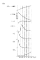
図13は要求負荷Lに対するスロットル弁16の開度、EGR制御弁23の開度、EGR率、空燃比、噴射時期及び噴射量を示している。図13に示されるように要求負荷Lの低い第1の運転領域Iではスロットル弁16の開度は要求負荷Lが高くなるにつれて全閉近くから半開程度まで徐々に増大せしめられ、EGR制御弁23の開度は要求負荷Lが高くなるにつれて全閉近くから全開まで徐々に増大せしめられる。また、図13に示される例では第1の運転領域IではEGR率がほぼ70パーセントとされており、空燃比はわずかばかりリーンなリーン空燃比とされている。
【0048】
言い換えると第1の運転領域IではEGR率がほぼ70パーセントとなり、空燃比がわずかばかりリーンなリーン空燃比となるようにスロットル弁16の開度及びEGR制御弁23の開度が制御される。なお、この時の空燃比は空燃比センサ21の出力信号に基づいてEGR制御弁23の開度を補正することによって目標リーン空燃比に制御される。また、第1の運転領域Iでは圧縮上死点TDC前に燃料噴射が行われる。この場合、噴射開始時期θSは要求負荷Lが高くなるにつれて遅くなり、噴射完了時期θEも噴射開始時期θSが遅くなるにつれて遅くなる。
【0049】
なお、アイドリング運転時にはスロットル弁16は全閉近くまで閉弁され、この時にはEGR制御弁23も全閉近くまで閉弁せしめられる。スロットル弁16を全閉近くまで閉弁すると圧縮始めの燃焼室5内の圧力が低くなるために圧縮圧力が小さくなる。圧縮圧力が小さくなるとピストン4による圧縮仕事が小さくなるために機関本体1の振動が小さくなる。即ち、アイドリング運転時には機関本体1の振動を抑制するためにスロットル弁16が全閉近くまで閉弁せしめられる。
【0050】
一方、機関の運転領域が第1の運転領域Iから第2の運転領域IIに変わるとスロットル弁16の開度が半開状態から全開方向へステップ状に増大せしめられる。この時に図13に示す例ではEGR率がほぼ70パーセントから40パーセント以下までステップ状に減少せしめられ、空燃比がステップ状に大きくされる。即ち、EGR率が多量のスモークを発生するEGR率範囲(図9)を飛び越えるので機関の運転領域が第1の運転領域Iから第2の運転領域IIに変わるときに多量のスモークが発生することがない。
【0051】
第2の運転領域IIでは従来から行われている燃焼が行われる。この燃焼方法では煤及びNOXが若干発生するが低温燃焼に比べて熱効率は高く、従って機関の運転領域が第1の運転領域Iから第2の運転領域IIに変わると図13に示されるように噴射量がステップ状に低減せしめられる。
【0052】
第2の運転領域IIではスロットル弁16は一部を除いて全開状態に保持され、EGR制御弁23の開度は要求負荷Lが高くなると次第に小さくされる。この運転領域IIではEGR率は要求負荷Lが高くなるほど低くなり、空燃比は要求負荷Lが高くなるほど小さくなる。ただし、空燃比は要求負荷Lが高くなってもリーン空燃比とされる。また、第2の運転領域IIでは噴射開始時期θSは圧縮上死点TDC付近とされる。
【0053】
図14は第1の運転領域Iにおける空燃比A/Fを示している。図14において、A/F=15.5、A/F=16、A/F=17、A/F=18で示される各曲線は夫々空燃比が15.5、16、17、18である時を示しており、各曲線間の空燃比は比例配分により定められる。図14に示されるように第1の運転領域Iでは空燃比がリーンとなっており、更に第1の運転領域Iでは要求負荷Lが低くなるほど空燃比A/Fがリーンとされる。
【0054】
即ち、要求負荷Lが低くなるほど燃焼による発熱量が少なくなる。従って要求負荷Lが低くなるほどEGR率を低下させても低温燃焼を行うことができる。EGR率を低下させると空燃比は大きくなり、従って図14に示されるように要求負荷Lが低くなるにつれて空燃比A/Fが大きくされる。空燃比A/Fが大きくなるほど燃料消費率は向上し、従ってできる限り空燃比をリーンにするために本実施例では要求負荷Lが低くなるにつれて空燃比A/Fが大きくされる。
【0055】
なお、空燃比を図14に示す目標空燃比とするのに必要なスロットル弁16の目標開度STが図15(A)に示されるように要求負荷L及び機関回転数Nの関数としてマップの形で予めROM32内に記憶されており、空燃比を図14に示す目標空燃比とするのに必要なEGR制御弁23の目標開度SEが図15(B)に示されるように要求負荷L及び機関回転数Nの関数としてマップの形で予めROM32内に記憶されている。
【0056】
図16は第二燃焼、即ち従来の燃焼方法による普通の燃焼が行われるときの目標空燃比を示している。なお、図16においてA/F=24、A/F=35、A/F=45、A/F=60で示される各曲線は夫々目標空燃比24、35、45、60を示している。空燃比をこの目標空燃比とするのに必要なスロットル弁16の目標開度STが図17(A)に示されるように要求負荷L及び機関回転数Nの関数としてマップの形で予めROM32内に記憶されており、空燃比をこの目標空燃比とするのに必要なEGR制御弁23の目標開度SEが図17(B)に示されるように要求負荷L及び機関回転数Nの関数としてマップの形で予めROM32内に記憶されている。
【0057】
こうして、本実施例のディーゼルエンジンでは、アクセルペダル40の踏み込み量L及び機関回転数Nとに基づき、第一燃焼、すなわち、低温燃焼と、第二燃焼、すなわち、普通の燃焼とが切り換えられ、各燃焼において、アクセルペダル40の踏み込み量L及び機関回転数Nとに基づき、図15又は図17に示すマップによってスロットル弁16及びEGR弁の開度制御が実施される。
【0058】
図18は排気浄化装置を示す平面断面図である。本排気浄化装置は、マフラ100内に構成されている。マフラ100は、例えば、機関排気系の最下流部に位置している。マフラ100内は、互いに長手方向に隣接する第一室101、第二室102、及び第三室103に区画されている。最も上流側に位置する第一室101には、パティキュレートフィルタ70が、その両側にそれぞれ空間を残して配置されている。マフラ100の外側には、マフラ100を機関排気系に接続する切換部71が設けられている。切換部71は、機関排気系との接続に使用される上流側開口71bと、上流側開口71bに対向する下流側開口71cと、上流側開口71bと下流側開口71cとを遮断可能な切換弁71aとを有している。
【0059】
切換部71には、さらに、図18に示す弁体71aの一方の遮断位置において上流側開口71bと連通する第一開口71dと、下流側開口71cと連通する第二開口71eとが設けられている。この第一開口71dは、第一接続管72によってマフラ100内の第一室101における一方の空間に連通されている。また、切換部71の第二開口71eは、第二接続管73によってマフラ100内の第一室101における他方の空間に連通されている。また、切換部71の下流側開口71cは、第三接続管74によってマフラ100内の第二室102へ連通されている。
【0060】
マフラ10内において、第一室101に第三室103が隣接し、第三室103に第二室102が隣接している。第二室102には、触媒装置75が、その両側にそれぞれ空間を残して配置されている。第三接続管74は、第一室101の一方の空間、他方の空間、及びパティキュレートフィルタ70と、第三室103と、第二室102の他方の空間及び触媒装置75とを貫通して、第二室102の一方の空間に開口している。
【0061】
弁体71aの一方の遮断位置において、排気ガスは、図18に矢印で示すように、上流側開口71bから切換部71へ流入した後に、第一開口71dから第一接続管72を介してマフラ100の第一室101における一方の空間へ流入し、第一室101において一方の空間から他方の空間へ向けてパティキュレートフィルタ70を通過する。その後、第一室101の他方の空間から第二接続管73を介して切換部71の第二開口71eへ達し、切換部71の下流側開口71cを通り、第三接続管74を介して、マフラ100の第二室102における一方の空間へ流入する。その後、第二室102において一方の空間から他方の空間へ触媒装置75を通過し、第二室102の他方の空間と第三室103とを連通する第一連通管104を介して第三室103へ流入し、第二室102を貫通して第三室103とマフラ100外部とを連通する第二連通管105を介して第三室103から大気中へ放出される。
【0062】
こうして、マフラ10内において、第一室101は最も上流側となり、第一室101に隣接する第三室103ではなくて第二室102が次に上流側となり、第三室103は最も下流側となっている。第二室102の実質的な容積、すなわち、第三接続管74、第二連通管105、及び触媒装置75の担体自身(担体内の空間は含まれない)によって排除される容積を除いた容積は、第一室101及び第三室103の同様な実質的な容積に比較して小さくなっており、それにより、排気ガスは、第一室101から第二室102へ流入する際に収縮し、第二室102から第三室103へ流入する際に膨張することにより、音圧が下げられる。
【0063】
弁体71aは、負圧アクチュエータ又はステップモータ等によって回動され、前述した図18に示す一方の遮断位置だけでなく、図19に示す他方の遮断位置とすることができる。この他方の遮断位置において、排気ガスは、図19に矢印で示すように、上流側開口71bから切換部71へ流入した後に、第二開口71eから第二接続管73を介してマフラ100の第一室101における他方の空間へ流入し、第一室101において他方の空間から一方の空間へ向けてパティキュレートフィルタ70を通過する。その後、第一室101の一方の空間から第一接続管72を介して切換部71の第一開口71dへ達し、切換部71の下流側開口71cを通り、第三接続管74へ流入する。その後は、一方の遮断位置と同様に、第二室102において触媒装置75を通過して第三室103へ流入し、大気中へ放出される。
【0064】
こうして、本排気浄化装置において、切換部71を有すると共にパティキュレートフィルタ70がマフラ100内の区画された第一室101内に配置されているために、弁体71aを遮断位置の一方から他方へ切り換えることにより、第一室101に配置されたパティキュレートフィルタ70の排気上流側と排気下流側とを容易に逆転することが可能となる。いずれの遮断位置においても、排気ガスは、マフラ100において、第一室101から第二室102を介して第三室103へ流入するために、音圧を良好に低減することができる。
【0065】
また、弁体71aを二つの遮断位置の一方から他方へ切り換える時に、弁体71aは図20に示すような中間位置となり、排気ガスは、図20に矢印で示すように、マフラ100の第一室101を通過することなく、すなわち、パティキュレートフィルタ70を通過することなく、第二室102へ流入することとなる。
【0066】
パティキュレートフィルタにおいては、排気ガスの流入を容易にするために大きな開口面積が必要とされるが、本排気浄化装置では、機関排気系において本来的に大きな断面積を有するマフラ内にパティキュレートフィルタを配置することにより、容易に車両搭載が可能となる。
【0067】
図21にパティキュレートフィルタ70の構造を示す。なお、図21において、(A)はパティキュレートフィルタ70の正面図であり、(B)は側面断面図(第三接続管74の貫通位置とは異なる位置での側面断面図)である。これらの図に示すように、本パティキュレートフィルタ70は、図18に示される横幅が高さに比較して大きな長円正面形状を有し、例えば、コージライトのような多孔質材料から形成されたハニカム構造をなすウォールフロー型であり、多数の軸線方向に延在する隔壁54によって細分された多数の軸線方向空間を有している。隣接する二つの軸線方向空間において、栓53によって、一方は排気下流側で閉鎖され、他方は排気上流側で閉鎖される。こうして、隣接する二つの軸線方向空間の一方は排気ガスの流入通路50となり、他方は流出通路51となり、排気ガスは、図21(B)に矢印で示すように、必ず隔壁54を通過する。排気ガス中のパティキュレートは、隔壁54の細孔の大きさに比較して非常に小さいものであるが、隔壁54の排気上流側表面及び隔壁54内の細孔表面上に衝突して捕集される。こうして、各隔壁54は、パティキュレートを捕集する捕集壁として機能する。本パティキュレートフィルタ70において、捕集されたパティキュレートを酸化除去するために、隔壁54の両側表面上、及び、好ましくは隔壁54内の細孔表面上にもアルミナ等を使用して以下に説明する活性酸素放出剤と貴金属触媒とが担持されている。
【0068】
活性酸素放出剤とは、活性酸素を放出することによってパティキュレートの酸化を促進するものであり、好ましくは、周囲に過剰酸素が存在すると酸素を取込んで酸素を保持しかつ周囲の酸素濃度が低下すると保持した酸素を活性酸素の形で放出するものである。
【0069】
貴金属触媒としては、通常、白金Ptが用いられており、活性酸素放出剤としてカリウムK、ナトリウムNa、リチウムLi、セシウムCs、ルビジウムRbのようなアルカリ金属、バリウムBa、カルシウムCa、ストロンチウムSrのようなアルカリ土類金属、ランタンLa、イットリウムYのような希土類、および遷移金属から選ばれた少なくとも一つが用いられている。
【0070】
なお、この場合、活性酸素放出剤としては、カルシウムCaよりもイオン化傾向の高いアルカリ金属又はアルカリ土類金属、即ちカリウムK、リチウムLi、セシウムCs、ルビジウムRb、バリウムBa、ストロンチウムSrを用いることが好ましい。
【0071】
次に、このような活性酸素放出剤を担持するパティキュレートフィルタによって、捕集されたパティキュレートがどのように酸化除去されるかについて、白金PtおよびカリウムKの場合を例にとって説明する。他の貴金属、アルカリ金属、アルカリ土類金属、希土類、遷移金属を用いても同様なパティキュレート除去作用が行われる。
【0072】
ディーゼルエンジンでは通常空気過剰のもとで燃焼が行われ、従って排気ガスは多量の過剰空気を含んでいる。即ち、吸気通路および燃焼室内に供給された空気と燃料との比を排気ガスの空燃比と称すると、この空燃比はリーンとなっている。また、燃焼室内ではNOが発生するので排気ガス中にはNOが含まれている。また、燃料中にはイオウSが含まれており、このイオウSは燃焼室内で酸素と反応してSO2となる。従って排気ガス中にはSO2が含まれている。従って過剰酸素、NOおよびSO2を含んだ排気ガスがパティキュレートフィルタ70の排気上流側へ流入することになる。
【0073】
図22(A)および(B)はパティキュレートフィルタ70における排気ガス接触面の拡大図を模式的に表わしている。なお、図22(A)および(B)において60は白金Ptの粒子を示しており、61はカリウムKを含んでいる活性酸素放出剤を示している。
【0074】
上述したように排気ガス中には多量の過剰酸素が含まれているので排気ガスがパティキュレートフィルタの排ガス接触面内に接触すると、図22(A)に示されるようにこれら酸素O2がO2 −又はO2−の形で白金Ptの表面に付着する。一方、排気ガス中のNOは白金Ptの表面上でO2 −又はO2−と反応し、NO2となる(2NO+O2→2NO2)。次いで生成されたNO2の一部は白金Pt上で酸化されつつ活性酸素放出剤61内に吸収され、カリウムKと結合しながら図22(A)に示されるように硝酸イオンNO3 −の形で活性酸素放出剤61内に拡散し、硝酸カリウムKNO3を生成する。このようにして、本実施例では、排気ガスに含まれるNOxをパティキュレートフィルタ70に吸収し、大気中への放出量を大幅に減少させることができる。
【0075】
一方、上述したように排気ガス中にはSO2も含まれており、このSO2もNOと同様なメカニズムによって活性酸素放出剤61内に吸収される。即ち、上述したように酸素O2がO2 −又はO2−の形で白金Ptの表面に付着しており、排気ガス中のSO2は白金Ptの表面でO2 −又はO2−と反応してSO3となる。次いで生成されたSO3の一部は白金Pt上で更に酸化されつつ活性酸素放出剤61内に吸収され、カリウムKと結合しながら硫酸イオンSO4 2−の形で活性酸素放出剤61内に拡散し、硫酸カリウムK2SO4を生成する。このようにして活性酸素放出触媒61内には硝酸カリウムKNO3および硫酸カリウムK2SO4が生成される。
【0076】
排気ガス中のパティキュレートは、図22(B)において62で示されるように、パティキュレートフィルタに担持された活性酸素放出剤61の表面上に付着する。この時、パティキュレート62と活性酸素放出剤61との接触面では酸素濃度が低下する。酸素濃度が低下すると酸素濃度の高い活性酸素放出剤61内との間で濃度差が生じ、斯くして活性酸素放出剤61内の酸素がパティキュレート62と活性酸素放出剤61との接触面に向けて移動しようとする。その結果、活性酸素放出剤61内に形成されている硝酸カリウムKNO3がカリウムKと酸素OとNOとに分解され、酸素Oがパティキュレート62と活性酸素放出剤61との接触面に向かい、NOが活性酸素放出剤61から外部に放出される。外部に放出されたNOは下流側の白金Pt上において酸化され、再び活性酸素放出剤61内に吸収される。
【0077】
一方、このとき活性酸素放出剤61内に形成されている硫酸カリウムK2SO4もカリウムKと酸素OとSO2とに分解され、酸素Oがパティキュレート62と活性酸素放出剤61との接触面に向かい、SO2が活性酸素放出剤61から外部に放出される。外部に放出されたSO2は下流側の白金Pt上において酸化され、再び活性酸素放出剤61内に吸収される。但し、硫酸カリウムK2SO4は、安定化しているために、硝酸カリウムKNO3に比べて活性酸素を放出し難い。
【0078】
一方、パティキュレート62と活性酸素放出剤61との接触面に向かう酸素Oは硝酸カリウムKNO3や硫酸カリウムK2SO4のような化合物から分解された酸素である。化合物から分解された酸素Oは高いエネルギを有しており、極めて高い活性を有する。従ってパティキュレート62と活性酸素放出剤61との接触面に向かう酸素は活性酸素Oとなっている。これら活性酸素Oがパティキュレート62に接触するとパティキュレート62は数分から数十分の短時間で輝炎を発することなく酸化せしめられる。また、パティキュレート62を酸化する活性酸素Oは、活性酸素放出剤61へNO及びSO2が吸収される時にも放出される。すなわち、NOXは酸素原子の結合及び分離を繰り返しつつ活性酸素放出剤61内において硝酸イオンNO3 −の形で拡散するものと考えられ、この間にも活性酸素が発生する。パティキュレート62はこの活性酸素によっても酸化せしめられる。また、このようにパティキュレートフィルタ70上に付着したパティキュレート62は活性酸素Oによって酸化せしめられるがこれらパティキュレート62は排気ガス中の酸素によっても酸化せしめられる。
【0079】
ところで白金Pt及び活性酸素放出剤61はパティキュレートフィルタの温度が高くなるほど活性化するので単位時間当りに活性酸素放出剤61から放出される活性酸素Oの量はパティキュレートフィルタの温度が高くなるほど増大する。また、当然のことながら、パティキュレート自身の温度が高いほど酸化除去され易くなる。従ってパティキュレートフィルタ上において単位時間当りに輝炎を発することなくパティキュレートを酸化除去可能な酸化除去可能微粒子量はパティキュレートフィルタの温度が高くなるほど増大する。
【0080】
図23の実線は単位時間当りに輝炎を発することなく酸化除去可能な酸化除去可能微粒子量Gを示しており、図23において横軸はパティキュレートフィルタの温度TFを示している。なお、図23は単位時間を1秒とした場合の、すなわち、1秒当たりの酸化除去可能微粒子量Gを示しているがこの単位時間としては、1分、10分等任意の時間を採用することができる。例えば、単位時間として10分を用いた場合には単位時間当たりの酸化除去可能微粒子量Gは10分間当たりの酸化除去可能微粒子量Gを表すことになり、この場合でもパティキュレートフィルタ70上において単位時間当たりに輝炎を発することなく酸化除去可能な酸化除去可能微粒子量Gは図23に示されるようにパティキュレートフィルタ70の温度が高くなるほど増大する。
【0081】
さて、単位時間当りに燃焼室から排出されるパティキュレートの量を排出微粒子量Mと称するとこの排出微粒子量Mが酸化除去可能微粒子量Gよりも少ないとき、例えば、1秒当たりの排出微粒子量Mが1秒当たりの酸化除去可能微粒子量Gよりも少ないとき、或いは10分当たりの排出微粒子量Mが10分当たりの酸化除去可能微粒子量Gよりも少ないとき、即ち図23の領域Iでは燃焼室から排出された全てのパティキュレートがパティキュレートフィルタ70上において輝炎を発することなく順次短時間のうちに酸化除去せしめられる。これに対し、排出微粒子量Mが酸化除去可能微粒子量Gよりも多いとき、即ち図23の領域IIでは全てのパティキュレートを順次酸化するには活性酸素量が不足している。図24(A)〜(C)はこのような場合におけるパティキュレートの酸化の様子を示している。
【0082】
即ち、全てのパティキュレートを酸化するには活性酸素量が不足している場合には図24(A)に示すようにパティキュレート62が活性酸素放出剤61上に付着するとパティキュレート62の一部のみが酸化され、十分に酸化されなかったパティキュレート部分がパティキュレートフィルタの排気上流側面上に残留する。次いで活性酸素量が不足している状態が継続すると次から次へと酸化されなかったパティキュレート部分が排気上流面上に残留し、その結果図24(B)に示されるようにパティキュレートフィルタの排気上流面が残留パティキュレート部分63によって覆われるようになる。
【0083】
このような残留パティキュレート部分63は、次第に酸化され難いカーボン質に変質し、また、排気上流面が残留パティキュレート部分63によって覆われると白金PtによるNO,SO2の酸化作用及び活性酸素放出剤61による活性酸素の放出作用が抑制される。それにより、時間を掛ければ徐々に残留パティキュレート部分63を酸化させることができるが、図24(C)に示されるように残留パティキュレート部分63の上に別のパティキュレート64が次から次へと堆積する。即ち、パティキュレートが積層状に堆積すると、これらパティキュレートは、白金Ptや活性酸素放出剤から距離を隔てているために、例え酸化され易いパティキュレートであっても活性酸素によって酸化されることはない。従ってこのパティキュレート64上に更に別のパティキュレートが次から次へと堆積する。即ち、排出微粒子量Mが酸化除去可能微粒子量Gよりも多い状態が継続するとパティキュレートフィルタ上にはパティキュレートが積層状に堆積してしまう。
【0084】
このように図23の領域Iではパティキュレートはパティキュレートフィルタ上において輝炎を発することなく短時間のうちに酸化せしめられ、図23の領域IIではパティキュレートがパティキュレートフィルタ上に積層状に堆積する。従って、排出微粒子量Mと酸化除去可能微粒子量Gとの関係を領域Iにすれば、パティキュレートフィルタ上へのパティキュレートの堆積を防止することができる。その結果、パティキュレートフィルタ70における排気ガス流の圧損は全くと言っていいほど変化することなくほぼ一定の最小圧損値に維持される。斯くして機関の出力低下を最小限に維持することができる。しかしながら、これが常に実現されるとは限らず、何もしなければパティキュレートフィルタにはパティキュレートが堆積することがある。
【0085】
本実施例では、設定時間又は設定走行距離毎に切換部71の弁体71aを現在の遮断位置から他方の遮断位置へ回動させ、パティキュレートフィルタ70の排気上流側と排気下流側とを逆転させるようになっている。
【0086】
図25は、パティキュレートフィルタの隔壁54の拡大断面図である。前述したように、排気ガスが主に衝突する隔壁54の排気上流側表面及び細孔内の排気ガス流対向面は、一方の捕集面としてパティキュレートを衝突捕集し、活性酸素放出剤により放出された活性酸素によって捕集パティキュレートを酸化除去するが、設定時間又は設定走行距離を走行する間には、図23の領域IIでの運転が実施されることもあり、図25(A)は格子で示すように、酸化除去が不十分となってパティキュレートが残留することがある。この程度のパティキュレートの堆積に伴うパティキュレートフィルタの排気抵抗は車両走行に悪影響を与えるほどではないが、さらにパティキュレートが堆積すれば、機関出力の大幅な低下等の問題を発生する。しかしながら、この時点でパティキュレートフィルタの排気上流側と排気下流側とが逆転されれば、隔壁54の一方の捕集面に残留するパティキュレート上には、さらにパティキュレートが堆積することはなく、一方の捕集面から放出される活性酸素によって残留パティキュレートは徐々に酸化除去される。また、隔壁の細孔内に残留するパティキュレートは、逆方向の排気ガス流によって、図25(B)に示すように、容易に破壊されて細分化され、下流側へ移動する。
【0087】
それにより、細分化された多くのパティキュレートは、隔壁の細孔内に分散し、すなわち、パティキュレートは流動することにより、隔壁の細孔内表面に担持させた活性酸素放出剤と直接的に接触して酸化除去される機会が多くなる。こうして、隔壁の細孔内にも活性酸素放出剤を担持させることで、残留パティキュレートを格段に酸化除去させ易くなる。さらに、この酸化除去に加えて、排気ガスの逆流によって上流側となった隔壁54の他方の捕集面、すなわち、現在において排気ガスが主に衝突する隔壁54の排気上流側表面及び細孔内の排気ガス流対向面(一方の捕集面とは反対側の関係となる)では、排気ガス中の新たなパティキュレートが付着して活性酸素放出剤から放出された活性酸素によって酸化除去される。これらの酸化除去の際に活性酸素放出剤から放出された活性酸素の一部は、排気ガスと共に下流側へ移動し、排気ガスの逆流によっても依然として残留するパティキュレートを酸化除去する。
【0088】
すなわち、隔壁における一方の捕集面の残留パティキュレートには、この捕集面から放出される活性酸素だけでなく、排気ガスの逆流によって隔壁の他方の捕集面でのパティキュレートの酸化除去に使用された残りの活性酸素が排気ガスによって到来する。それにより、弁体の切り換え時点において、隔壁の一方の捕集面にある程度パティキュレートが積層状に堆積していたとしても、排気ガスを逆流させれば、残留パティキュレート上に堆積するパティキュレートへも活性酸素が到来することに加えて、さらにパティキュレートが堆積することはないために、堆積パティキュレートは徐々に酸化除去され、次回の逆流までに、ある程度の時間があれば、この間で十分に酸化除去可能である。
【0089】
こうして、パティキュレートフィルタの排気上流側と排気下流側とを逆転させることにより、パティキュレートフィルタ捕集壁の第一捕集面と第二捕集面とが交互に使用され、常に単一の捕集面でパティキュレートを捕集する場合に比較して各捕集面でのパティキュレート捕集量を低減することができ、パティキュレートの酸化除去に有利となり、パティキュレートをパティキュレートフィルタに堆積し難くさせることができる。パティキュレートフィルタへ比較的多量のパティキュレートが堆積すると、何らかの要因によって堆積パティキュレートの温度が約600℃に昇温された時に、堆積パティキュレートが一度に燃焼して多量の燃焼熱を発生させ、パティキュレートフィルタが溶損することがあるために、本実施例のように、パティキュレートをパティキュレートフィルタへ堆積させ難くすることは重要である。
【0090】
弁体の切り換えは、設定時間又は設定走行距離毎のように定期的に実施しなくても不定期に実施するようにしても良い。また、機関減速時毎に弁体を切り換えるようにしても良い。機関減速時の判断には、運転者が車両の減速を意図する動作、例えば、アクセルペダルの開放、ブレーキペダルの踏み込み、及びフューエルカット等のいずれかを検出することが利用可能である。
【0091】
また、パティキュレートフィルタへのパティキュレート堆積量が設定量となった時に弁体を切り換えるようにしても良い。パティキュレート堆積量の推定には、例えば、パティキュレート堆積量の増加に伴って増大するパティキュレートフィルタ70の直上流側と直下流側との間の差圧を利用することができ、また、パティキュレート堆積量の増加に伴って低下するパティキュレートフィルタ所定隔壁上の電気抵抗値を利用しても良く、また、パティキュレート堆積量の増加に伴って低下するパティキュレートフィルタ所定隔壁上の光の透過率又は反射率を利用しても良い。また、図23のグラフに基づき、現在の機関運転状態から推定される排出微粒子量Mが現在の機関運転状態から推定されるパティキュレートフィルタの温度を考慮した酸化除去可能微粒子量Gを上回る時の差(M−G)をパティキュレート堆積量として積算するようにしても良い。
【0092】
また、排気ガスの空燃比をリッチにすると、すなわち、排気ガス中の酸素濃度を低下させると、活性酸素放出剤61から外部に活性酸素Oが一気に放出される。この一気に放出された活性酸素Oによって、堆積パティキュレートは酸化され易いものとなって容易に酸化除去される。一方、空燃比がリーンに維持されていると白金Ptの表面が酸素で覆われ、いわゆる白金Ptの酸素被毒が生じる。このような酸素被毒が生じるとNOXに対する酸化作用が低下するためにNOXの吸収効率が低下し、斯くして活性酸素放出剤61からの活性酸素放出量が低下する。しかしながら空燃比がリッチにされると白金Pt表面上の酸素が消費されるために酸素被毒が解消され、従って空燃比が再びリッチからリーンに切り換えられるとNOXに対する酸化作用が強まるためにNOXの吸収効率が高くなり、斯くして活性酸素放出剤61からの活性酸素放出量が増大する。従って、空燃比がリーンに維持されている時に空燃比を時折リーンからリッチに一時的に切り換えるとその都度白金Ptの酸素被毒が解消されるために空燃比がリーンである時の活性酸素放出量が増大し、斯くしてパティキュレートフィルタ70上におけるパティキュレートの酸化作用を促進することができる。さらに、この酸素被毒の解消は、言わば、還元物質の燃焼であるために、発熱を伴ってパティキュレートフィルタを昇温させる。それにより、パティキュレートフィルタにおける酸化除去可能微粒子量が向上し、さらに、残留及び堆積パティキュレートの酸化除去が容易となる。弁体71aによってパティキュレートフィルタの排気上流側と排気下流側とを切り換えた直後に排気ガスの空燃比をリッチにすれば、パティキュレートが残留していないパティキュレートフィルタ隔壁における他方の捕集面では、一方の捕集面に比較して活性酸素を放出し易いために、さらに多量に放出される活性酸素によって、一方の捕集面の残留パティキュレートをさらに確実に酸化除去することができる。もちろん、弁体71aの切り換えとは無関係に時折排気ガスの空燃比をリッチにしても良く、それにより、パティキュレートフィルタへパティキュレートが残留及び堆積し難くなる。
【0093】
排気ガスの空燃比をリッチにする方法としては、例えば、前述の低温燃焼を実施すれば良い。また、単に燃焼空燃比をリッチにしても良い。また、圧縮行程での通常の主燃料噴射に加えて、機関燃料噴射弁によって排気行程又は膨張行程において気筒内に燃料を噴射(ポスト噴射)しても良く、又は、吸気行程において気筒内に燃料を噴射(ビゴム噴射)しても良い。もちろん、ポスト噴射又はビゴム噴射は、主燃料噴射との間に必ずしもインターバルを設ける必要はない。また、機関排気系に燃料を供給することも可能である。
【0094】
ところで、本実施例のパティキュレートフィルタでは、前述したように排気ガス中のNOXを良好に吸収するが、パティキュレートフィルタの構造は、前述したように、捕集壁の細孔を排気ガスが通過するウォールフロー型であり、触媒を担持する隔壁に沿って排気ガスが流れる一般的な触媒装置との比較において、同じ大きさで同量の排気ガスを通過させるためには、捕集壁間の寸法を隔壁間の寸法に比較して大きくしなければならない。それにより、パティキュレートフィルタにおいて排気ガスが捕集壁表面に担持された活性酸素放出剤と接触する機会は、モノリス型の触媒装置において触媒と接触する機会より少ない。また、排気ガスは、捕集壁の細孔を通過する際には、この細孔内に担持された活性酸素放出剤に接触するが、主には、捕集壁の表面に担持された活性酸素放出剤にしか接触しない。しかしながら、多数の細孔によって捕集壁表面の触媒担持面積はそれほど大きくない。こうして、NOXを吸収する活性酸素放出剤をパティキュレートフィルタに担持させても、排気ガス中のNOXを十分に浄化することはできない。
【0095】
本実施例では、マフラ100の第一室101内に配置されたパティキュレートフィルタの排気上流側と排気下流側との逆転に係わらずに常にパティキュレートフィルタの下流側となる位置、すなわち、マフラ100の第二室102内に触媒装置75を配置している。この触媒装置75は、パティキュレートフィルタ70と共にマフラ100内に配置されているために、パティキュレートフィルタ70での活性酸素によるパティキュレートの酸化除去及び貴金属触媒での還元物質の燃焼によってパティキュレートフィルタが昇温する際にマフラ100全体が昇温される。それにより、触媒装置をマフラの下流側に配置する場合に比較して、本触媒装置75はマフラ100からの受熱によって高温度に維持される機会が増大する。こうして、触媒装置75に担持させた触媒は活性化している機会が多い。
【0096】
それにより、本触媒装置75に、前述した貴金属触媒及び活性酸素放出剤として使用可能な物質をNOX吸蔵還元触媒として担持することにより、パティキュレートフィルタにおいて吸収されなかったNOXを良好に吸収して大気中への放出量を十分に低減することが可能となる。もちろん、触媒装置73に担持するNOX触媒は、NOX吸蔵還元触媒に限定されることなく、例えば、NOX選択還元触媒のような他の種類のNOXを浄化する触媒としても良い。
【0097】
また、前述したように、パティキュレートフィルタへ還元物質を含むリッチ排気ガスを流入させる際に、又は、低温燃焼を実施してHC及びCOを比較的多く含む排気ガスがパティキュレートフィルタへ流入する際に、還元物質の全てがパティキュレートフィルタの貴金属触媒で酸化されるか又は活性酸素放出剤から放出されたNOXを還元するのに使用されるとは限らず、パティキュレートフィルタを通過する還元物質を浄化する必要がある。触媒装置75にNOX吸蔵還元触媒が担持されていれば、その貴金属触媒及び放出されるNOXの還元浄化によってパティキュレートフィルタを通過する還元物質の浄化が可能となるが、触媒装置75として、少なくとも貴金属触媒のような酸化触媒を担持していれば、パティキュレートフィルタを通過する還元物質の浄化が可能である。
【0098】
前述したように、弁体71aを切り換える際には、弁体71aは図20に示すような中間位置となり、排気ガスがパティキュレートフィルタをバイパスすることとなる。この時においても、排気ガスは触媒装置75を通過するために、排気ガス中の有害物質を触媒装置75によって良好に浄化することができる。しかしながら、排気ガス中のパティキュレートは触媒装置75によっては浄化することができないために、弁体71aの切り換えは、フューエルカットにより排気ガス中にパティキュレートが含まれない機関減速時に実施することが好ましい。
【0099】
また、フューエルカット時は排気ガス温度が低く、パティキュレートフィルタを温度低下させることがあるために、パティキュレートフィルタの酸化除去可能微粒子量を高く維持するためには、機関減速時には弁体71aを積極的に中間位置として排気ガスがパティキュレートフィルタをバイパスするようにすることが好ましい。
【0100】
図26は、前述した排気浄化装置の変形例を示す断面平面図である。本排気浄化装置と前述した排気浄化装置とにおいて、同一要素は同じ参照番号によって示されている。二つの排気浄化装置の違いを以下に説明する。本排気浄化装置では、マフラ100の第一室101における他方の空間と切換部71の第二開口71eとを接続する第二接続管73’が、第一室101における一方の空間とパティキュレートフィルタ70とを貫通している。それにより、第二接続管がマフラ100の横側に出っ張ることがなく、本排気浄化装置としてのマフラの車両搭載性を改善することができる。
【0101】
前述した排気浄化装置は、パティキュレートフィルタ70及び触媒装置75を拡張型マフラに配置するようにした。しかしながら、これは本発明を限定するものではなく、他の方式、例えば、干渉型、共鳴型、又は吸音型等のマフラにおける上流側にパティキュレートフィルタを、下流側に触媒装置を配置すれば、触媒装置を良好に昇温させて触媒が活性化している機会を増大させることができ、マフラを通過して大気中へ放出される有害物質を良好に低減することができる。
【0102】
パティキュレートフィルタ70をマフラの一つの隔室(第一室)内に配置することにより、前述したように、切換部71との組み合わせによってパティキュレートフィルタの排気上流側と排気下流側とを逆転が容易となるが、もちろん、この逆転機構が設けられていない場合には、パティキュレートフィルタと触媒装置とを別の隔室へ配置する必要はなく、同じ隔室内に隣接配置することも可能である。この場合には、マフラ内が複数の隔室に区画されている必要もない。
【0103】
ところで、排気ガス中のカルシウムCaはSO3が存在すると、硫酸カルシウムCaSO4を生成する。この硫酸カルシウムCaSO4は、酸化除去され難く、パティキュレートフィルタ上にアッシュとして残留することとなる。従って、硫酸カルシウムの残留によるパティキュレートフィルタの目詰まりを防止するためには、活性酸素放出剤61としてカルシウムCaよりもイオン化傾向の高いアルカリ金属又はアルカリ土類金属、例えばカリウムKを用いることが好ましく、それにより、活性酸素放出剤61内に拡散するSO3はカリウムKと結合して硫酸カリウムK2SO4を形成し、カルシウムCaはSO3と結合することなくパティキュレートフィルタの隔壁を通過する。従ってパティキュレートフィルタがアッシュによって目詰まりすることがなくなる。こうして、前述したように活性酸素放出剤61としてはカルシウムCaよりもイオン化傾向の高いアルカリ金属又はアルカリ土類金属、即ちカリウムK、リチウムLi、セシウムCs、ルビジウムRb、バリウムBa、ストロンチウムSrを用いることが好ましいことになる。
【0104】
また、活性酸素放出剤としてパティキュレートフィルタに白金Ptのような貴金属のみを担持させても、白金Ptの表面上に保持されるNO2又はSO3から活性酸素を放出させることができる。ただし、この場合には酸化除去可能微粒子量Gを示す実線は図23に示す実線に比べて若干右側に移動する。また、活性酸素放出剤としてセリアを用いることも可能である。セリアは、排気ガス中の酸素濃度が高いと酸素を吸収し(Ce2O3→2CeO2)、排気ガス中の酸素濃度が低下すると活性酸素を放出する(2CeO2→Ce2O3)ものであるために、パティキュレートの酸化除去のために、排気ガス中の空燃比を定期的又は不定期にリッチにする必要がある。セリアに代えて、鉄又は錫を使用しても良い。
【0105】
また、活性酸素放出剤として排気ガス中のNOx浄化に使用されるNOx吸蔵還元触媒を用いることも可能である。この場合においては、NOx又はSOxを放出させるために排気ガスの空燃比を少なくとも一時的にリッチにする必要がある。
【0106】
本実施例において、パティキュレートフィルタ自身が活性酸素放出剤を担持して、この活性酸素放出剤が放出する活性酸素によりパティキュレートが酸化除去されるものとしたが、これは、本発明を限定するものではない。例えば、活性酸素及び活性酸素と同等に機能する二酸化窒素等のパティキュレート酸化成分は、パティキュレートフィルタ又はそれに担持させた物質から放出されても、外部からパティキュレートフィルタへ流入するようにしても良い。パティキュレート酸化成分が外部から流入する場合においても、パティキュレートを捕集するために、捕集壁の第一捕集面と第二捕集面とを交互に使用することはパティキュレートの堆積防止に有効である。すなわち、排気下流側となった一方の捕集面では、新たにパティキュレートが堆積することはなく、この堆積パティキュレートを、他方の捕集面から流入するパティキュレート酸化成分によって徐々にでも酸化除去して、堆積パティキュレートをある程度の時間で十分に酸化除去することが可能である。この間において、他方の捕集面では、パティキュレートの捕集と共にパティキュレート酸化成分による酸化が行われるために、前述同様な効果がもたらされる。
【0107】
本実施例のディーゼルエンジンは、低温燃焼と通常燃焼とを切り換えて実施するものとしたが、これは本発明を限定するものではなく、もちろん、通常燃焼のみを実施するディーゼルエンジン、又はパティキュレートを排出するガソリンエンジンにも本発明は適用可能である。
【0108】
【発明の効果】
このように、本発明による内燃機関の排気浄化装置によれば、機関排気系に位置するマフラと、マフラ内に配置されて、排気ガス中のパティキュレートを捕集し、捕集したパティキュレートが酸化させられるパティキュレートフィルタと、マフラ内に配置されて、パティキュレートフィルタの下流側に位置する触媒装置、とを具備している。それにより、比較的大きな断面積が必要なパティキュレートフィルタは、機関排気系において比較的大きな断面積を有するマフラ内に配置され、車両搭載性の問題が発生することはない。また、マフラ内においてパティキュレートフィルタの下流側には触媒装置が配置されており、この触媒装置では、比較的高温度に維持されるマフラからの受熱によって担持された触媒の活性化の機会が多く、パティキュレートフィルタが配置されたマフラからパティキュレート以外の有害物質が排出される以前に、この有害物質を良好に浄化し、大気中への放出を防止することができる。
【0109】
また、マフラ内は少なくとも第一室と第二室とに区画され、第二室より上流側に位置する第一室内にはパティキュレートフィルタが配置され、第二室には触媒装置が配置され、第一室におけるパティキュレートフィルタの排気上流側と排気下流側とを逆転するための逆転手段を具備し、パティキュレートフィルタはパティキュレートを捕集するための捕集壁を有し、捕集壁は第一捕集面と第二捕集面とを有し、逆転手段によってパティキュレートフィルタの排気下流側と排気上流側とが逆転されることによりパティキュレートを捕集するために捕集壁の第一捕集面と第二捕集面とが交互に使用されるようになっているために、パティキュレートフィルタへパティキュレートが堆積し難くすることができる。すなわち、運転状態によっては、パティキュレートの酸化が不十分となってパティキュレートフィルタ捕集壁の第一捕集面にはある程度のパティキュレートが残留することがあるが、逆転手段によるパティキュレートフィルタの排気上流側と排気下流側との逆転によって、捕集壁の第一捕集面には新たにパティキュレートが堆積することはなく、堆積パティキュレートを徐々に酸化除去可能である。同時に、捕集壁の第二捕集面によってパティキュレートの捕集及び酸化が開始される。こうして、パティキュレートの捕集に第一捕集面と第二捕集面とが交互に使用されると、常に単一の捕集面でパティキュレートを捕集する場合に比較して、各捕集面でのパティキュレート捕集量を低減することができ、パティキュレートの酸化除去に有利となる。
【図面の簡単な説明】
【図1】本発明による排気浄化装置を備えるディーゼルエンジンの概略縦断面図である。
【図2】図1の燃焼室の拡大縦断面図である。
【図3】図1のシリンダヘッドの底面図である。
【図4】燃焼室の側面断面図である。
【図5】吸排気弁のリフトと燃料噴射を示す図である。
【図6】スモークおよびNOxの発生量等を示す図である。
【図7】燃焼圧を示す図である。
【図8】燃料分子を示す図である。
【図9】スモークの発生量とEGR率との関係を示す図である。
【図10】噴射燃料量と混合ガス量との関係を示す図である。
【図11】第1の運転領域Iおよび第2の運転領域IIを示す図である。
【図12】空燃比センサの出力を示す図である。
【図13】スロットル弁の開度等を示す図である。
【図14】第1の運転領域Iにおける空燃比を示す図である。
【図15】スロットル弁等の目標開度のマップを示す図である。
【図16】第二燃焼における空燃比を示す図である。
【図17】スロットル弁等の目標開度を示す図である。
【図18】排気浄化装置を示す断面平面図である。
【図19】図18とは異なる弁体の遮断位置を示す排気浄化装置の平面図である。
【図20】弁体の中間位置を示す排気浄化装置の平面図である。
【図21】パティキュレートフィルタの構造を示す図である。
【図22】パティキュレートの酸化作用を説明するための図である。
【図23】酸化除去可能微粒子量とパティキュレートフィルタの温度との関係を示す図である。
【図24】パティキュレートの堆積作用を説明するための図である。
【図25】パティキュレートフィルタの隔壁の拡大断面図である。
【図26】図18の排気浄化装置の変形例を示す断面平面図である。
【符号の説明】
6…燃料噴射弁
16…スロットル弁
70…パティキュレートフィルタ
71…切換部
71a…弁体
75…触媒装置
100…マフラ[0001]
BACKGROUND OF THE INVENTION
The present invention relates to an exhaust emission control device for an internal combustion engine.
[0002]
[Prior art]
Particulates mainly composed of soot are contained in the exhaust gas of internal combustion engines, particularly diesel engines. Since particulates are harmful substances, it has been proposed to arrange a filter for collecting particulates in the engine exhaust system before release into the atmosphere. Such a filter is required to burn off the collected particulates in order to prevent an increase in exhaust resistance due to clogging.
[0003]
In such filter regeneration, ignition and combustion occur when the particulates reach approximately 600 ° C., but the exhaust gas temperature of the diesel engine is considerably lower than 600 ° C. at normal times, and usually means such as heating the filter itself. is required.
[0004]
In Japanese Patent Publication No. 7-106290, if a platinum group metal and an alkaline earth metal oxide are supported on a filter, the particulates on the filter are about 400 ° C., which is the exhaust gas temperature of a diesel engine at normal times. It is disclosed that it burns continuously.
[0005]
Even if the particulate filter can burn out the particulates in the exhaust gas before it is released into the atmosphere, the particulate filter will prevent the engine exhaust itself from becoming a large exhaust resistance. It has a larger cross-sectional area than the passage cross-sectional area of the system, and in practice it is not easy to arrange in the engine exhaust system.
[0006]
In order to facilitate the arrangement of the particulate filter in the engine exhaust system, Japanese Utility Model Laid-Open No. 1-149915 proposes to arrange the particulate filter in a muffler having a relatively large cross-sectional area in the engine exhaust system. Has been.
[0007]
[Problems to be solved by the invention]
Thus, the problem of vehicle mountability is solved by arranging the particulate filter in the muffler. By the way, the exhaust gas passing through the muffler in which the particulate filter is disposed may contain harmful substances other than the particulates, and a catalyst device for purifying these harmful substances is required. If such a catalyst device is arranged on the downstream side of the muffler, it is difficult to raise the temperature by the exhaust gas because it is far from the engine body, so the catalyst is not activated in the catalyst device, and harmful substances that pass through the muffler are It is released into the atmosphere without being purified well.
[0008]
Therefore, the object of the present invention is to oxidize the particulates collected by disposing the particulate filter in the muffler on the particulate filter, and prevent harmful substances other than particulates from being released into the atmosphere through the muffler. It is an object of the present invention to provide an exhaust emission control device for an internal combustion engine.
[0009]
[Means for Solving the Problems]
An exhaust emission control device for an internal combustion engine according to claim 1 of the present invention includes a muffler located in an engine exhaust system, and the particulates in the exhaust gas collected and collected in the muffler. A particulate filter that oxidizes the curate; and a catalyst device that is disposed in the muffler and is located downstream of the particulate filter.In the exhaust gas purification apparatus for an internal combustion engine, the inside of the muffler is partitioned into at least a first chamber and a second chamber, and the particulate filter is disposed in the first chamber located upstream from the second chamber, The catalyst device is disposed in the second chamber, and includes a reversing means for reversing the exhaust upstream side and the exhaust downstream side of the particulate filter in the first chamber, and the particulate filter captures the particulates. A collecting wall for collecting, the collecting wall having a first collecting surface and a second collecting surface, and the exhaust filter downstream side and the exhaust upstream side of the particulate filter by the reverse means. The first collecting surface and the second collecting surface of the collecting wall are alternately used to collect the particulates by being reversed.
[0011]
And claims according to the invention2An exhaust emission control device for an internal combustion engine according to claim 1,1In the exhaust gas purification apparatus for an internal combustion engine according to the item 1, an active oxygen release agent is supported on the particulate filter, and the active oxygen released from the active oxygen release agent oxidizes the particulate.
[0012]
And claims according to the invention3An exhaust emission control device for an internal combustion engine according to claim 1,2In the exhaust gas purification apparatus for an internal combustion engine according to claim 1, the active oxygen release agent takes in oxygen when excess oxygen is present in the surrounding area and retains oxygen, and when the surrounding oxygen concentration decreases, the retained oxygen is converted into the form of active oxygen. It is characterized by being discharged with
[0013]
And claims according to the invention4An internal combustion engine exhaust gas purification apparatus according to claim 13The exhaust gas purification apparatus for an internal combustion engine according to any one of the above, wherein the catalyst device carries an oxidation catalyst.
[0014]
And claims according to the invention5An internal combustion engine exhaust gas purification apparatus according to claim 13The exhaust gas purification apparatus for an internal combustion engine according to any one of the above, wherein the catalyst device is NOXIt is characterized by carrying a catalyst.
[0015]
DETAILED DESCRIPTION OF THE INVENTION
FIG. 1 is a schematic longitudinal sectional view of a four-stroke diesel engine equipped with an exhaust emission control device according to the present invention, FIG. 2 is an enlarged longitudinal sectional view of a combustion chamber in the diesel engine of FIG. 1, and FIG. It is a bottom view of the cylinder head in the diesel engine of. Referring to FIGS. 1 to 3, 1 is an engine body, 2 is a cylinder block, 3 is a cylinder head, 4 is a piston, 5a is a cavity formed on the top surface of the
[0016]
As shown in FIG. 1, an air-
[0017]
On the other hand, each
[0018]
An
[0019]
As shown in FIGS. 2 and 3, in the embodiment according to the present invention, the
[0020]
FIG. 4 shows a case where additional fuel is injected from the
[0021]
Normally, no additional fuel Qa is injected, and only main injection Qm is performed. FIG. 6 shows the change in output torque when the air-fuel ratio A / F (horizontal axis in FIG. 6) is changed by changing the opening degree and EGR rate of the
[0022]
As shown in FIG. 6, when the air-fuel ratio A / F is decreased by increasing the EGR rate, the EGR rate becomes around 40% and the amount of smoke generated increases when the air-fuel ratio A / F becomes about 30 To start. Next, when the EGR rate is further increased and the air-fuel ratio A / F is decreased, the amount of smoke generated increases rapidly and reaches a peak. Next, when the EGR rate is further increased and the air-fuel ratio A / F is reduced, the smoke suddenly decreases, the EGR rate is increased to 65% or more, and when the air-fuel ratio A / F is near 15.0, the smoke becomes almost zero. . That is, almost no wrinkles occur. At this time, the output torque of the engine slightly decreases, and NOxThe amount of generation is considerably low. On the other hand, the generation amount of HC and CO starts increasing at this time.
[0023]
FIG. 7A shows a change in combustion pressure in the
[0024]
The following can be said from the experimental results shown in FIGS. That is, first, when the air-fuel ratio A / F is 15.0 or less and the amount of smoke generated is almost zero, as shown in FIG.xThe amount of generated is significantly reduced. NOxThe reduction in the amount of generation means that the combustion temperature in the
[0025]
Secondly, when the amount of smoke generated, that is, the amount of soot is substantially zero, the HC and CO emissions increase as shown in FIG. This means that the hydrocarbons are discharged without growing to the soot. That is, linear hydrocarbons and aromatic hydrocarbons as shown in FIG. 8 contained in the fuel are thermally decomposed to form soot precursors when the temperature is raised in an oxygen-deficient state. A soot made of a solid in which carbon atoms are assembled is produced. In this case, the actual soot formation process is complicated, and it is not clear what form the soot precursor will take, but in any case the hydrocarbons shown in FIG. After that, it will grow up to heels. Therefore, as described above, when the generation amount of soot becomes almost zero, the emission amount of HC and CO increases as shown in FIG. 6. At this time, HC is a precursor of soot or a hydrocarbon in the previous state. .
[0026]
Summarizing these considerations based on the experimental results shown in FIGS. 6 and 7, the amount of soot generated becomes almost zero when the combustion temperature in the
[0027]
By the way, when the hydrocarbon generation process stops in the state of soot precursor, the temperature of the fuel and its surroundings, that is, the above-mentioned certain temperature changes depending on various factors such as the type of fuel, the air-fuel ratio and the compression ratio. I can't say how many times, but this certain temperature is NOxTherefore, this certain temperature is NO.xIt can be defined to some extent from the generation amount of. That is, as the EGR rate increases, the temperature of the fuel during combustion and the surrounding gas decreases, and NOxThe amount of generation decreases. At this time NOxOf 10 p. p. When it becomes around m or less, wrinkles hardly occur. Therefore, the above mentioned temperature is NOxOf 10 p. p. It almost corresponds to the temperature when it is around m or below.
[0028]
Once soot is produced, it cannot simply be purified by post-treatment using a catalyst having an oxidizing function. On the other hand, the soot precursor or the hydrocarbon in the previous state can be easily purified by post-treatment using a catalyst having an oxidation function. Like this, NOxIt is extremely effective for purifying exhaust gas to reduce the generation amount of hydrocarbons and to discharge hydrocarbons from the
[0029]
Now, in order to stop the growth of hydrocarbons in a state before soot is generated, it is necessary to suppress the temperature of the fuel and the surrounding gas in the
[0030]
That is, if there is only air around the fuel, the evaporated fuel immediately reacts with oxygen in the air and burns. In this case, the temperature of the air away from the fuel does not increase so much, and only the temperature around the fuel becomes extremely high locally. That is, at this time, the air away from the fuel hardly performs the endothermic action of the combustion heat of the fuel. In this case, since the combustion temperature becomes extremely high locally, the unburned hydrocarbons that have received this heat of combustion produce soot.
[0031]
On the other hand, the situation is slightly different when fuel is present in a mixed gas of a large amount of inert gas and a small amount of air. In this case, the evaporated fuel diffuses around and reacts with oxygen mixed in the inert gas and burns. In this case, since the combustion heat is absorbed by the surrounding inert gas, the combustion temperature does not rise so much. That is, the combustion temperature can be kept low. That is, the presence of the inert gas plays an important role in suppressing the combustion temperature, and the combustion temperature can be kept low by the endothermic action of the inert gas.
[0032]
In this case, in order to suppress the temperature of the fuel and the surrounding gas to a temperature lower than the temperature at which soot is generated, an amount of inert gas that can absorb a sufficient amount of heat is required. Therefore, if the amount of fuel increases, the amount of inert gas required increases accordingly. In this case, the greater the specific heat of the inert gas, the stronger the endothermic action. Therefore, the inert gas is preferably a gas having a large specific heat. This point, CO2Since EGR gas has a relatively large specific heat, it can be said that it is preferable to use EGR gas as an inert gas.
[0033]
FIG. 9 shows the relationship between the EGR rate and smoke when EGR gas is used as the inert gas and the degree of cooling of the EGR gas is changed. That is, in FIG. 9, curve A shows the case where the EGR gas is strongly cooled and the EGR gas temperature is maintained at about 90 ° C., and curve B shows the case where the EGR gas is cooled by a small cooling device. Curve C shows the case where the EGR gas is not forcibly cooled.
[0034]
As shown by curve A in FIG. 9, when the EGR gas is cooled strongly, soot generation peaks when the EGR rate is slightly lower than 50%. In this case, the EGR rate is increased to about 55% or more. If you do, almost no wrinkles will occur. On the other hand, as shown by the curve B in FIG. 9, when the EGR gas is slightly cooled, the amount of soot generated peaks when the EGR rate is slightly higher than 50%. In this case, the EGR rate is almost 65% or more. If this is done, almost no wrinkles will occur.
[0035]
Further, as shown by the curve C in FIG. 9, when the EGR gas is not forcibly cooled, the amount of soot generated reaches a peak when the EGR rate is around 55%. In this case, the EGR rate is approximately 70%. If the percentage is exceeded, almost no wrinkles occur. FIG. 9 shows the amount of smoke generated when the engine load is relatively high. When the engine load is reduced, the EGR rate at which the amount of soot reaches a peak slightly decreases, and the EGR rate at which soot hardly occurs. The lower limit is also slightly reduced. Thus, the lower limit of the EGR rate at which soot hardly occurs varies depending on the degree of cooling of the EGR gas and the engine load.
[0036]
FIG. 10 shows the amount of mixed gas of EGR gas and air necessary for making the temperature of the fuel and the surrounding gas lower than the temperature at which soot is generated when EGR gas is used as the inert gas. And the ratio of the air in this gas mixture amount, and the ratio of the EGR gas in this gas mixture are shown. In FIG. 10, the vertical axis indicates the total intake gas amount sucked into the
[0037]
Referring to FIG. 10, the ratio of air, that is, the amount of air in the mixed gas, indicates the amount of air necessary to completely burn the injected fuel. That is, in the case shown in FIG. 10, the ratio between the air amount and the injected fuel amount is the stoichiometric air-fuel ratio. On the other hand, in FIG. 10, the ratio of EGR gas, that is, the amount of EGR gas in the mixed gas is used to make the temperature of the fuel and its surrounding gas lower than the temperature at which soot is formed when the injected fuel is burned. The minimum EGR gas amount is shown. This EGR gas amount is approximately 55% or more in terms of EGR rate, and is 70% or more in the embodiment shown in FIG. That is, if the total intake gas amount sucked into the
[0038]
If the amount of fuel injection increases, the amount of heat generated when the fuel burns increases. Therefore, in order to maintain the temperature of the fuel and the surrounding gas at a temperature lower than the temperature at which soot is generated, the amount of heat absorbed by the EGR gas Must be increased. Therefore, as shown in FIG. 10, the amount of EGR gas must be increased as the amount of injected fuel increases. That is, the amount of EGR gas needs to increase as the required load increases.
[0039]
On the other hand, in the load region Z2 of FIG. 10, the total intake gas amount X necessary for preventing the generation of soot exceeds the total intake gas amount Y that can be sucked. Therefore, in this case, in order to supply the total intake gas amount X necessary for preventing the generation of soot into the
[0040]
As described above, FIG. 10 shows the case where the fuel is burned under the stoichiometric air-fuel ratio, but even if the air amount is smaller than the air amount shown in FIG. 10 in the low load operation region Z1 shown in FIG. That is, even if the air-fuel ratio is rich, NO is generated while preventing the generation of soot.xOf 10 p. p. m or less, and even in the low load region Z1 shown in FIG. 10, even if the air amount is larger than the air amount shown in FIG. NO while preventing the occurrence of soot even if leanxOf 10 p. p. It can be around m or less.
[0041]
That is, when the air-fuel ratio is made rich, the fuel becomes excessive, but the combustion temperature is suppressed to a low temperature, so that the excess fuel does not grow to soot, and so no soot is generated. At this time, NOxHowever, only a very small amount is generated. On the other hand, when the average air-fuel ratio is lean, or even when the air-fuel ratio is the stoichiometric air-fuel ratio, a small amount of soot is generated if the combustion temperature is high, but in the present invention the soot is suppressed to a low temperature, so Not generated at all. In addition, NOxHowever, only a very small amount is generated.
[0042]
As described above, in the engine low load operation region Z1, regardless of the air-fuel ratio, that is, whether the air-fuel ratio is rich, the stoichiometric air-fuel ratio, or the average air-fuel ratio is lean, no soot is generated.xThe amount of generated is extremely small. Therefore, considering the improvement of the fuel consumption rate, it can be said that it is preferable to make the average air-fuel ratio lean at this time.
[0043]
By the way, the temperature of the fuel during combustion in the combustion chamber and the surrounding gas can be suppressed to a temperature below the temperature at which the growth of hydrocarbons stops midway only when the heat generated by combustion is small and the engine load is relatively low. Therefore, in the embodiment according to the present invention, when the engine load is relatively low, the temperature of the fuel during combustion and the surrounding gas temperature are suppressed to a temperature below the temperature at which hydrocarbon growth stops halfway, so that the first combustion, that is, low temperature combustion is performed. When the engine load is relatively high, the second combustion, that is, the combustion normally performed conventionally is performed. Here, the first combustion, that is, low temperature combustion, as is clear from the above description, the amount of inert gas in the combustion chamber is larger than the worst inert gas amount at which the amount of soot generation is maximum, and soot is almost generated. The second combustion, that is, the combustion that is normally performed in the past, is combustion in which the amount of inert gas in the combustion chamber is smaller than the worst inert gas amount that generates the largest amount of soot. Say.
[0044]
FIG. 11 shows a first operation region I in which the first combustion, that is, low-temperature combustion is performed, and a second combustion region II in which the second combustion, that is, combustion by the conventional combustion method is performed. In FIG. 11, the vertical axis L indicates the amount of depression of the
[0045]
That is, when the engine operating state is in the first operating region I and low-temperature combustion is being performed, if the required load L exceeds the first boundary X (N) that is a function of the engine speed N, the operating region is It is determined that the operation has shifted to the second operation region II, and combustion by the conventional combustion method is performed. Next, when the required load L becomes lower than the second boundary Y (N) that is a function of the engine speed N, it is determined that the operating region has shifted to the first operating region I, and low temperature combustion is performed again.
[0046]
FIG. 12 shows the output of the air-
[0047]
FIG. 13 shows the opening degree of the
[0048]
In other words, in the first operating region I, the EGR rate is approximately 70%, and the opening degree of the
[0049]
During the idling operation, the
[0050]
On the other hand, when the engine operating region changes from the first operating region I to the second operating region II, the opening of the
[0051]
Conventional combustion is performed in the second operation region II. In this combustion method, soot and NOXHowever, when the engine operating region is changed from the first operating region I to the second operating region II, the injection amount is reduced stepwise as shown in FIG. To be harassed.
[0052]
In the second operation region II, the
[0053]
FIG. 14 shows the air-fuel ratio A / F in the first operating region I. In FIG. 14, the curves indicated by A / F = 15.5, A / F = 16, A / F = 17, and A / F = 18 have air-fuel ratios of 15.5, 16, 17, and 18, respectively. Time is shown, and the air-fuel ratio between the curves is determined by proportional distribution. As shown in FIG. 14, the air-fuel ratio is lean in the first operation region I, and in the first operation region I, the air-fuel ratio A / F is leaner as the required load L becomes lower.
[0054]
That is, the lower the required load L, the smaller the amount of heat generated by combustion. Therefore, low temperature combustion can be performed even if the EGR rate is reduced as the required load L is reduced. When the EGR rate is lowered, the air-fuel ratio increases, so as shown in FIG. 14, the air-fuel ratio A / F increases as the required load L decreases. As the air-fuel ratio A / F increases, the fuel consumption rate improves. Therefore, in order to make the air-fuel ratio as lean as possible, in this embodiment, the air-fuel ratio A / F increases as the required load L decreases.
[0055]
Note that the target opening ST of the
[0056]
FIG. 16 shows the target air-fuel ratio when the second combustion, that is, the normal combustion by the conventional combustion method is performed. In FIG. 16, the curves indicated by A / F = 24, A / F = 35, A / F = 45, and A / F = 60 indicate the target air-
[0057]
Thus, in the diesel engine of the present embodiment, the first combustion, that is, low-temperature combustion, and the second combustion, that is, normal combustion are switched based on the depression amount L of the
[0058]
FIG. 18 is a plan sectional view showing the exhaust emission control device. The exhaust purification device is configured in the
[0059]
The switching
[0060]
In the
[0061]
At one blocking position of the
[0062]
Thus, in the
[0063]
The
[0064]
Thus, in the present exhaust purification apparatus, since the switching
[0065]
Further, when the
[0066]
In the particulate filter, a large opening area is required for facilitating the inflow of exhaust gas. However, in the present exhaust purification apparatus, the particulate filter is placed in a muffler that has an inherently large cross-sectional area in the engine exhaust system. By disposing, the vehicle can be easily mounted.
[0067]
FIG. 21 shows the structure of the
[0068]
The active oxygen release agent is an agent that promotes oxidation of particulates by releasing active oxygen. Preferably, oxygen is taken in and retained when excess oxygen is present in the surroundings, and the oxygen concentration in the surroundings is increased. When lowered, the retained oxygen is released in the form of active oxygen.
[0069]
As the noble metal catalyst, platinum Pt is usually used, and as the active oxygen release agent, alkali metals such as potassium K, sodium Na, lithium Li, cesium Cs, and rubidium Rb, barium Ba, calcium Ca, and strontium Sr are used. At least one selected from alkaline earth metals, lanthanum La, rare earths such as yttrium Y, and transition metals is used.
[0070]
In this case, as the active oxygen release agent, alkali metal or alkaline earth metal having a higher ionization tendency than calcium Ca, that is, potassium K, lithium Li, cesium Cs, rubidium Rb, barium Ba, and strontium Sr are used. preferable.
[0071]
Next, how the collected particulates are oxidized and removed by such a particulate filter carrying an active oxygen release agent will be described by taking platinum Pt and potassium K as an example. The same particulate removal action can be performed using other noble metals, alkali metals, alkaline earth metals, rare earths, and transition metals.
[0072]
In a diesel engine, combustion is usually performed under excess air, and therefore the exhaust gas contains a large amount of excess air. That is, when the ratio of air and fuel supplied to the intake passage and the combustion chamber is called the air-fuel ratio of the exhaust gas, the air-fuel ratio is lean. Further, since NO is generated in the combustion chamber, the exhaust gas contains NO. The fuel also contains sulfur S, which reacts with oxygen in the combustion chamber to react with SO.2It becomes. Therefore, in the exhaust gas, SO2It is included. Therefore excess oxygen, NO and SO2The exhaust gas containing the gas flows into the exhaust upstream side of the
[0073]
22A and 22B schematically show an enlarged view of the exhaust gas contact surface in the
[0074]
As described above, since a large amount of excess oxygen is contained in the exhaust gas, when the exhaust gas comes into contact with the exhaust gas contact surface of the particulate filter, as shown in FIG.2Is O2 −Or O2-It adheres to the surface of platinum Pt. On the other hand, NO in the exhaust gas is O on the surface of platinum Pt.2 −Or O2-Reacts with NO2(2NO + O2→ 2NO2). Then the generated NO2Part of the oxygen is absorbed on the active
[0075]
On the other hand, as described above, the exhaust gas contains SO.2Is also included, this SO2Is absorbed into the active
[0076]
Particulates in the exhaust gas adhere to the surface of the active
[0077]
On the other hand, potassium sulfate K formed in the active
[0078]
On the other hand, the oxygen O toward the contact surface between the particulate 62 and the active
[0079]
By the way, since platinum Pt and the active
[0080]
The solid line in FIG. 23 indicates the amount G of fine particles that can be removed by oxidation without emitting a bright flame per unit time. In FIG. 23, the horizontal axis indicates the temperature TF of the particulate filter. FIG. 23 shows the amount G of fine particles that can be oxidized and removed per second when the unit time is 1 second. As this unit time, an arbitrary time such as 1 minute or 10 minutes is adopted. be able to. For example, when 10 minutes is used as the unit time, the oxidizable and removable fine particle amount G per unit time represents the oxidizable and removable fine particle amount G per 10 minutes. Even in this case, the unit on the
[0081]
Now, when the amount of particulate discharged from the combustion chamber per unit time is referred to as discharged particulate amount M, when this discharged particulate amount M is smaller than the oxidizable and removable particulate amount G, for example, the amount of particulate discharged per second. When M is less than the amount G of fine particles that can be removed by oxidation per second, or when the amount M of fine particles discharged per 10 minutes is smaller than the amount of fine particles G that can be removed by oxidation every 10 minutes, that is, in region I in FIG. All the particulates discharged from the chamber are sequentially oxidized and removed within the short time without emitting a bright flame on the
[0082]
That is, when the amount of active oxygen is insufficient to oxidize all the particulates, if the
[0083]
Such residual
[0084]
In this way, in the region I in FIG. 23, the particulates are oxidized on the particulate filter in a short time without emitting a bright flame, and in the region II in FIG. 23, the particulates are deposited on the particulate filter in a stacked manner. To do. Therefore, if the relationship between the discharged fine particle amount M and the oxidizable and removable fine particle amount G is in the region I, the accumulation of particulates on the particulate filter can be prevented. As a result, the pressure loss of the exhaust gas flow in the
[0085]
In the present embodiment, the
[0086]
FIG. 25 is an enlarged cross-sectional view of the
[0087]
As a result, many of the finely divided particulates are dispersed in the pores of the partition walls, i.e., the particulates flow and directly with the active oxygen release agent supported on the pore inner surfaces of the partition walls. There are many opportunities for contact and oxidation removal. In this way, by supporting the active oxygen release agent in the pores of the partition walls, the residual particulates can be remarkably easily removed by oxidation. Further, in addition to this oxidation removal, the other collection surface of the
[0088]
That is, the residual particulates on one collecting surface in the partition wall are not only for the active oxygen released from this collecting surface, but also for the oxidation removal of the particulates on the other collecting surface of the partition wall by the backflow of exhaust gas. The remaining active oxygen used comes from the exhaust gas. As a result, even if particulates are accumulated to some extent on one collecting surface of the partition wall at the time of switching of the valve body, if the exhaust gas flows backward, the particulates accumulated on the residual particulates In addition to the arrival of active oxygen, no further particulates are deposited, so the deposited particulates are gradually oxidized and removed. Oxidation removal is possible.
[0089]
Thus, by reversing the exhaust upstream side and the exhaust downstream side of the particulate filter, the first collection surface and the second collection surface of the particulate filter collection wall are used alternately, and a single collection is always performed. Compared to collecting particulates on the collecting surface, the amount of particulates collected on each collecting surface can be reduced, which is advantageous for removing particulates by oxidation, and depositing the particulates on the particulate filter. Can be difficult. When a relatively large amount of particulates accumulates on the particulate filter, when the temperature of the deposited particulates is raised to about 600 ° C. due to some factor, the deposited particulates burn at a time to generate a large amount of combustion heat. Since the particulate filter may melt, it is important to make it difficult to deposit the particulate on the particulate filter as in this embodiment.
[0090]
The switching of the valve body may be performed irregularly even if it is not performed periodically, such as every set time or set travel distance. Further, the valve body may be switched every time the engine is decelerated. For the determination at the time of engine deceleration, it is possible to detect an operation that the driver intends to decelerate the vehicle, for example, release of an accelerator pedal, depression of a brake pedal, fuel cut, or the like.
[0091]
Further, the valve body may be switched when the amount of particulate accumulation on the particulate filter reaches a set amount. For the estimation of the particulate deposition amount, for example, the differential pressure between the upstream side and the downstream side of the
[0092]
Further, when the air-fuel ratio of the exhaust gas is made rich, that is, when the oxygen concentration in the exhaust gas is lowered, the active oxygen O is released from the active
[0093]
As a method for enriching the air-fuel ratio of the exhaust gas, for example, the low-temperature combustion described above may be performed. Alternatively, the combustion air-fuel ratio may be simply made rich. In addition to normal main fuel injection in the compression stroke, fuel may be injected into the cylinder (post-injection) in the exhaust stroke or expansion stroke by the engine fuel injection valve, or fuel in the cylinder in the intake stroke. May be jetted (bi-rubber jet). Of course, it is not always necessary to provide an interval between the post injection or the big rubber injection and the main fuel injection. It is also possible to supply fuel to the engine exhaust system.
[0094]
By the way, in the particulate filter of the present embodiment, as described above, NO in the exhaust gas.XAs described above, the structure of the particulate filter is a wall flow type in which the exhaust gas passes through the pores of the collection wall, and the exhaust gas generally flows along the partition wall supporting the catalyst. In order to allow the same amount of exhaust gas to pass through in comparison with a typical catalyst device, the size between the collection walls must be larger than the size between the partition walls. Thereby, the opportunity for the exhaust gas to come into contact with the active oxygen release agent supported on the surface of the collection wall in the particulate filter is less than the chance to come into contact with the catalyst in the monolith type catalyst device. Further, when the exhaust gas passes through the pores of the collection wall, it comes into contact with the active oxygen release agent carried in the pores, but mainly the active gas carried on the surface of the collection wall. Contact with oxygen release agent only. However, the catalyst support area on the surface of the collection wall is not so large due to the large number of pores. Thus, NOXEven if an active oxygen release agent that absorbs oxygen is supported on the particulate filter, NO in the exhaust gasXCan not be sufficiently purified.
[0095]
In this embodiment, the position always on the downstream side of the particulate filter irrespective of the reverse of the exhaust upstream side and the downstream exhaust side of the particulate filter disposed in the
[0096]
As a result, the
[0097]
Further, as described above, when rich exhaust gas containing a reducing substance flows into the particulate filter, or when exhaust gas containing a relatively large amount of HC and CO flows into the particulate filter by performing low temperature combustion. In addition, all of the reducing material is oxidized by the noble metal catalyst of the particulate filter or released from the active oxygen release agent.XIt is not necessarily used to reduce the amount of the substance, and it is necessary to purify the reducing substance that passes through the particulate filter. NO in
[0098]
As described above, when switching the
[0099]
In addition, when the fuel is cut, the exhaust gas temperature is low and the temperature of the particulate filter may be lowered. Therefore, in order to keep the particulate filter's oxidizable and removable fine particle amount high, the
[0100]
FIG. 26 is a cross-sectional plan view showing a modification of the above-described exhaust purification device. In the exhaust purification apparatus and the exhaust purification apparatus described above, the same elements are denoted by the same reference numerals. The difference between the two exhaust purification devices will be described below. In this exhaust purification apparatus, the
[0101]
In the above-described exhaust purification device, the
[0102]
By arranging the
[0103]
By the way, calcium Ca in the exhaust gas is SO.3In the presence of calcium sulfate CaSO4Is generated. This calcium sulfate CaSO4Is hardly removed by oxidation and remains as ash on the particulate filter. Therefore, in order to prevent the particulate filter from being clogged due to residual calcium sulfate, it is preferable to use an alkali metal or alkaline earth metal, such as potassium K, which has a higher ionization tendency than calcium Ca as the active
[0104]
Further, even when a particulate filter is loaded with only a noble metal such as platinum Pt as an active oxygen release agent, NO retained on the surface of platinum Pt.2Or SO3Active oxygen can be released from However, in this case, the solid line indicating the amount G of fine particles that can be removed by oxidation moves slightly to the right as compared with the solid line shown in FIG. It is also possible to use ceria as the active oxygen release agent. Ceria absorbs oxygen when the oxygen concentration in the exhaust gas is high (Ce2O3→ 2CeO2), Active oxygen is released when the oxygen concentration in the exhaust gas decreases (2CeO)2→ Ce2O3Therefore, it is necessary to enrich the air-fuel ratio in the exhaust gas regularly or irregularly in order to oxidize and remove particulates. Instead of ceria, iron or tin may be used.
[0105]
Moreover, NO in exhaust gas as an active oxygen release agentxNO used for purificationxIt is also possible to use an occlusion reduction catalyst. In this case, NOxOr SOxIn order to release the exhaust gas, it is necessary to at least temporarily enrich the air-fuel ratio of the exhaust gas.
[0106]
In this embodiment, the particulate filter itself carries the active oxygen release agent, and the particulates are oxidized and removed by the active oxygen released by the active oxygen release agent. However, this limits the present invention. It is not a thing. For example, the active oxygen and the particulate oxidation component such as nitrogen dioxide that functions in the same manner as the active oxygen may be released from the particulate filter or a substance carried on the particulate filter or may flow into the particulate filter from the outside. . Even when particulate oxidation components flow from the outside, it is possible to prevent the accumulation of particulates by alternately using the first and second collection surfaces of the collection wall to collect the particulates. It is effective for. That is, no particulates are newly deposited on one of the collection surfaces on the exhaust downstream side, and this accumulated particulate is gradually removed by oxidation by the particulate oxidizing component flowing from the other collection surface. Thus, the deposited particulate can be sufficiently oxidized and removed in a certain time. In the meantime, the other collecting surface is oxidized by the particulate oxidation component together with the collection of the particulates, and thus the same effect as described above is brought about.
[0107]
The diesel engine of the present embodiment is switched between low-temperature combustion and normal combustion, but this does not limit the present invention. Of course, a diesel engine that performs only normal combustion or a particulate is used. The present invention is also applicable to a gasoline engine that discharges.
[0108]
【The invention's effect】
As described above, according to the exhaust gas purification apparatus for an internal combustion engine according to the present invention, the muffler located in the engine exhaust system and the particulates in the exhaust gas that are disposed in the muffler are collected, and the collected particulates are There are provided a particulate filter to be oxidized, and a catalyst device which is disposed in the muffler and is located on the downstream side of the particulate filter. As a result, the particulate filter that requires a relatively large cross-sectional area is disposed in a muffler having a relatively large cross-sectional area in the engine exhaust system, so that there is no problem of vehicle mountability. In addition, a catalyst device is arranged in the muffler on the downstream side of the particulate filter, and in this catalyst device, there are many opportunities for activation of the catalyst supported by heat received from the muffler maintained at a relatively high temperature. Before harmful substances other than particulates are discharged from the muffler in which the particulate filter is disposed, the harmful substances can be well purified and released into the atmosphere.
[0109]
Also, MaThe inside of the hula is divided into at least a first chamber and a second chamber, a particulate filter is disposed in the first chamber located upstream from the second chamber, a catalyst device is disposed in the second chamber, A reversing means for reversing the exhaust gas upstream side and the exhaust gas downstream side of the particulate filter in the chamber, the particulate filter has a collecting wall for collecting the particulates, the collecting wall being the first A collecting surface and a second collecting surface, and the reversing means reverses the exhaust gas downstream side and the exhaust gas upstream side of the particulate filter so as to collect the particulates so as to collect the particulates. The collecting surface and the second collecting surface are used alternately.To becomeThus, it is possible to make it difficult for the particulates to be deposited on the particulate filter. That is, depending on the operating state, particulate oxidation may be insufficient, and some particulates may remain on the first collection surface of the particulate filter collection wall. By reversing the exhaust upstream side and the exhaust downstream side, new particulates are not deposited on the first collection surface of the collection wall, and the accumulated particulates can be gradually oxidized and removed. At the same time, particulate collection and oxidation are started by the second collection surface of the collection wall. In this way, when the first collection surface and the second collection surface are alternately used for collecting particulates, each collection is always compared to the case where the particulates are collected by a single collection surface. It is possible to reduce the amount of particulates collected on the collecting surface, which is advantageous for removing the particulates by oxidation.
[Brief description of the drawings]
FIG. 1 is a schematic longitudinal sectional view of a diesel engine equipped with an exhaust emission control device according to the present invention.
FIG. 2 is an enlarged longitudinal sectional view of the combustion chamber of FIG.
FIG. 3 is a bottom view of the cylinder head of FIG. 1;
FIG. 4 is a side sectional view of a combustion chamber.
FIG. 5 is a diagram showing intake / exhaust valve lift and fuel injection.
FIG. 6 Smoke and NOxIt is a figure which shows the generation amount of etc.
FIG. 7 is a diagram showing combustion pressure.
FIG. 8 is a diagram showing fuel molecules.
FIG. 9 is a diagram showing the relationship between the amount of smoke generated and the EGR rate.
FIG. 10 is a diagram showing the relationship between the amount of injected fuel and the amount of mixed gas.
FIG. 11 is a diagram showing a first operation region I and a second operation region II.
FIG. 12 is a diagram showing an output of an air-fuel ratio sensor.
FIG. 13 is a diagram showing an opening degree of a throttle valve and the like.
14 is a diagram showing an air-fuel ratio in a first operating region I. FIG.
FIG. 15 is a view showing a map of a target opening degree of a throttle valve or the like.
FIG. 16 is a diagram showing an air-fuel ratio in the second combustion.
FIG. 17 is a diagram showing a target opening degree of a throttle valve or the like.
FIG. 18 is a cross-sectional plan view showing the exhaust emission control device.
FIG. 19 is a plan view of the exhaust gas purification apparatus showing a valve body blocking position different from FIG. 18;
FIG. 20 is a plan view of the exhaust purification device showing an intermediate position of the valve body.
FIG. 21 is a diagram illustrating a structure of a particulate filter.
FIG. 22 is a diagram for explaining the oxidizing action of particulates.
FIG. 23 is a graph showing the relationship between the amount of fine particles that can be removed by oxidation and the temperature of the particulate filter.
FIG. 24 is a diagram for explaining the particulate deposition action.
FIG. 25 is an enlarged cross-sectional view of a partition wall of a particulate filter.
26 is a cross-sectional plan view showing a modification of the exhaust emission control device of FIG.
[Explanation of symbols]
6 ... Fuel injection valve
16 ... Throttle valve
70 ... Particulate filter
71 ... switching part
71a ... Valve
75 ... Catalyst device
100 ... Muffler
Claims (5)
Priority Applications (1)
| Application Number | Priority Date | Filing Date | Title |
|---|---|---|---|
| JP2001096796A JP3607987B2 (en) | 2001-03-29 | 2001-03-29 | Exhaust gas purification device for internal combustion engine |
Applications Claiming Priority (1)
| Application Number | Priority Date | Filing Date | Title |
|---|---|---|---|
| JP2001096796A JP3607987B2 (en) | 2001-03-29 | 2001-03-29 | Exhaust gas purification device for internal combustion engine |
Publications (2)
| Publication Number | Publication Date |
|---|---|
| JP2002295229A JP2002295229A (en) | 2002-10-09 |
| JP3607987B2 true JP3607987B2 (en) | 2005-01-05 |
Family
ID=18950672
Family Applications (1)
| Application Number | Title | Priority Date | Filing Date |
|---|---|---|---|
| JP2001096796A Expired - Fee Related JP3607987B2 (en) | 2001-03-29 | 2001-03-29 | Exhaust gas purification device for internal combustion engine |
Country Status (1)
| Country | Link |
|---|---|
| JP (1) | JP3607987B2 (en) |
Families Citing this family (1)
| Publication number | Priority date | Publication date | Assignee | Title |
|---|---|---|---|---|
| JP6981156B2 (en) * | 2017-10-02 | 2021-12-15 | いすゞ自動車株式会社 | Exhaust purification device for internal combustion engine |
Family Cites Families (5)
| Publication number | Priority date | Publication date | Assignee | Title |
|---|---|---|---|---|
| JPS52101314A (en) * | 1976-02-23 | 1977-08-25 | Kunitake Eda | Exhaust gas purifying apparatus for automobile |
| JPS5929721A (en) * | 1982-08-11 | 1984-02-17 | Caterpillar Mitsubishi Ltd | Catalytic conversion muffler for engine |
| JPH07106290B2 (en) * | 1984-04-23 | 1995-11-15 | エンゲルハード・コーポレーシヨン | Diesel Exhaust Particle Filter |
| JPH07189655A (en) * | 1993-12-27 | 1995-07-28 | Nippondenso Co Ltd | Exhaust emission control device for engine |
| JPH09217618A (en) * | 1996-02-09 | 1997-08-19 | Isuzu Ceramics Kenkyusho:Kk | Exhaust emission control device |
-
2001
- 2001-03-29 JP JP2001096796A patent/JP3607987B2/en not_active Expired - Fee Related
Also Published As
| Publication number | Publication date |
|---|---|
| JP2002295229A (en) | 2002-10-09 |
Similar Documents
| Publication | Publication Date | Title |
|---|---|---|
| JP3624892B2 (en) | Exhaust gas purification device for internal combustion engine | |
| JP3714327B2 (en) | Exhaust gas purification device for internal combustion engine | |
| US20020157387A1 (en) | A device for purifying the exhaust gas of an internal combustion engine | |
| EP1138889B1 (en) | Exhaust gas purifier for internal combustion engine and method for purifying exhaust gas | |
| JP3525912B2 (en) | Exhaust gas purification device for internal combustion engine | |
| JP3558055B2 (en) | Exhaust gas purification device for internal combustion engine | |
| JP3632633B2 (en) | Exhaust gas purification device for internal combustion engine | |
| JP3525854B2 (en) | Exhaust gas purification device for internal combustion engine | |
| JP3607987B2 (en) | Exhaust gas purification device for internal combustion engine | |
| JP3772729B2 (en) | Exhaust gas purification device for internal combustion engine | |
| JP4581287B2 (en) | Exhaust gas purification device for internal combustion engine | |
| JP3758514B2 (en) | Exhaust gas purification device for internal combustion engine | |
| JP3525853B2 (en) | Exhaust gas purification device for internal combustion engine | |
| JP3558015B2 (en) | Exhaust gas purification method for internal combustion engine | |
| JP3525871B2 (en) | Exhaust gas purification device for internal combustion engine | |
| JP3521878B2 (en) | Exhaust gas purification device for internal combustion engine | |
| JP3552674B2 (en) | Exhaust gas purification device for internal combustion engine | |
| JP3552673B2 (en) | Exhaust gas purification device for internal combustion engine | |
| JP3525904B2 (en) | Exhaust gas purification device for internal combustion engine | |
| JP3525860B2 (en) | Exhaust gas purification device for internal combustion engine | |
| JP3491599B2 (en) | Exhaust gas purification device for internal combustion engine | |
| JP3531581B2 (en) | Exhaust gas purification device for internal combustion engine | |
| JP2002295231A (en) | Exhaust gas purification device for internal combustion engine | |
| JP2002106328A (en) | Exhaust gas purification device for internal combustion engine | |
| JP2001342823A (en) | Exhaust gas purification device for internal combustion engine |
Legal Events
| Date | Code | Title | Description |
|---|---|---|---|
| A977 | Report on retrieval |
Free format text: JAPANESE INTERMEDIATE CODE: A971007 Effective date: 20040526 |
|
| A131 | Notification of reasons for refusal |
Free format text: JAPANESE INTERMEDIATE CODE: A131 Effective date: 20040615 |
|
| A521 | Request for written amendment filed |
Free format text: JAPANESE INTERMEDIATE CODE: A523 Effective date: 20040805 |
|
| TRDD | Decision of grant or rejection written | ||
| A01 | Written decision to grant a patent or to grant a registration (utility model) |
Free format text: JAPANESE INTERMEDIATE CODE: A01 Effective date: 20040907 |
|
| A61 | First payment of annual fees (during grant procedure) |
Free format text: JAPANESE INTERMEDIATE CODE: A61 Effective date: 20040920 |
|
| R150 | Certificate of patent or registration of utility model |
Free format text: JAPANESE INTERMEDIATE CODE: R150 |
|
| FPAY | Renewal fee payment (event date is renewal date of database) |
Free format text: PAYMENT UNTIL: 20081022 Year of fee payment: 4 |
|
| FPAY | Renewal fee payment (event date is renewal date of database) |
Free format text: PAYMENT UNTIL: 20081022 Year of fee payment: 4 |
|
| FPAY | Renewal fee payment (event date is renewal date of database) |
Free format text: PAYMENT UNTIL: 20091022 Year of fee payment: 5 |
|
| FPAY | Renewal fee payment (event date is renewal date of database) |
Free format text: PAYMENT UNTIL: 20091022 Year of fee payment: 5 |
|
| FPAY | Renewal fee payment (event date is renewal date of database) |
Free format text: PAYMENT UNTIL: 20101022 Year of fee payment: 6 |
|
| FPAY | Renewal fee payment (event date is renewal date of database) |
Free format text: PAYMENT UNTIL: 20101022 Year of fee payment: 6 |
|
| FPAY | Renewal fee payment (event date is renewal date of database) |
Free format text: PAYMENT UNTIL: 20111022 Year of fee payment: 7 |
|
| FPAY | Renewal fee payment (event date is renewal date of database) |
Free format text: PAYMENT UNTIL: 20111022 Year of fee payment: 7 |
|
| FPAY | Renewal fee payment (event date is renewal date of database) |
Free format text: PAYMENT UNTIL: 20121022 Year of fee payment: 8 |
|
| FPAY | Renewal fee payment (event date is renewal date of database) |
Free format text: PAYMENT UNTIL: 20121022 Year of fee payment: 8 |
|
| FPAY | Renewal fee payment (event date is renewal date of database) |
Free format text: PAYMENT UNTIL: 20131022 Year of fee payment: 9 |
|
| LAPS | Cancellation because of no payment of annual fees |